


8540
10 Sunnen Drive
St. Louis, MO 63143
telephone: 888-356-5362
fax: 314-781-2714
www.wellsbloomfield.com
BLOOMFIELD INDUSTRIES
OWNERS MANUAL
For
611
MODULAR
BREWING SYSTEMS
MODELS
POUR OVER AUTOMATIC AUTOMATIC
UNITS UNITS UNITS
WITH FAUCET
8542 8541 8540
8543 8573 8572
8571 8574
Includes:
Installation
Use & Care
Servicing Instructions
Model 8574 Brewer
with optional
8900-Series Glass Decanters
p/n 2M-75804 Rev. I M611 101026

NOTE: For your protection, please note that equipment in
this shipment was carefully inspected and packaged by
skilled personnel before leaving the factory.
Upon acceptance of this shipment, the transportation
company assumes full responsibility for its safe delivery.
IF SHIPMENT ARRIVES DAMAGED:
1. VISIBLE LOSS OR DAMAGE: Be certain that any
visible loss or damage is noted on the freight bill
or express receipt, and that the note of loss or damage
is signed by the delivery person.
2. FILE CLAIM FOR DAMAGE IMMEDIATELY:
Regardless of the extent of the damage.
3. CONCEALED LOSS OR DAMAGE: if damage is
unnoticed until the merchandise is unpacked, notify the
transportation company or carrier immediately, and file
“CONCEALED DAMAGE” claim with them. This
must be done within fifteen (15) days from the date the
delivery was made to you. Be sure to retain the
container for inspection.
Wells Bloomfield cannot assume liability for damage or loss
incurred in transit. We will, however, at your request, supply
you with the necessary documents to support your claim.
WARRANTY STATEMENT
SERVICE POLICY AND PROCEDURE GUIDE
ADDITIONAL WARRANTY EXCLUSIONS
SHIPPING DAMAGE CLAIMS PROCEDURE
1. Resetting of safety thermostats, circuit breakers,
overload protectors, or fuse replacements unless
warranted conditions are the cause.
2. All problems due to operation at voltages other than
specified on equipment nameplates; conversion to
correct voltage must be the customer’s responsibility.
3. All problems due to electrical connections not made in
accordance with electrical code requirements and
wiring diagrams supplied with the equipment.
4. Replacement of items subject to normal wear, to include
such items as knobs and light bulbs. Normal maintenance
functions including adjustment of thermostats, microswitches,
and replacement of fuses and indicating lights are not
covered under warranty.
5. All problems due to inadequate water supply, such as
fluctuating, or high or low water pressure.
6. All problems due to mineral/calcium deposits, or
contamination from chlorides/chlorines. De-liming is
considered a preventative maintenance function and is
not covered by warranty.
All electrical equipment manufactured by WELLS
BLOOMFIELD is warranted against defects in materials and
workmanship for a period of one year from the date of original
installation or eighteen (18) months from the date of shipment
from our factory, whichever comes first, and is for the benefit
of the original purchaser, except that:
a. airpots carry a 30 day parts warranty only.
b. dispensers; i.e., tea and coffee carry a 90 days parts
warranty only, decanters excluded.
THE FOREGOING OBLIGATION IS EXPRESSLY GIVEN IN
LIEU OF ANY OTHER WARRANTIES, EXPRESSED OR
IMPLIED, INCLUDING ANY IMPLIED WARRANTY OF
MERCHANTABILITY OR FITNESS FOR A PARTICULAR
PURPOSE, WHICH ARE HEREBY EXCLUDED.
BLOOMFIELD INDUSTRIES DIVISION / SPECIALTY
EQUIPMENT MANUFACTURING CORPORATION SHALL
NOT BE LIABLE FOR INDIRECT, INCIDENTAL OR
CONSEQUENTIAL DAMAGES OR LOSSES FROM ANY
CAUSE WHATSOEVER.
This warranty is void if it is determined that upon inspection by
an Authorized Service Agency that the equipment has been
modified, misused, misapplied, improperly installed, or
damaged in transit or by fire, flood or act of God.
It also does not apply if the serial nameplate has been
removed or unauthorized service personnel perform service.
The prices charged by Wells Bloomfield for its products are
based upon the limitations in this warranty. Seller’s obligation
under this warranty is limited to the repair of defects without
charge by a Wells Bloomfield Authorized Service Agency or
one of its sub-agencies. This service will be provided on
customer’s premises for non-portable models. Portable
models (a device with a cord and plug) must be taken or
shipped to the closest Authorized Service Agency,
transportation charges prepaid, for services.
In addition to restrictions contained in this warranty, specific
limitations are shown below (Additional Warranty Exclusions).
Wells Bloomfield Authorized Service Agencies are located in
principal cities.
This warranty is valid in the United States and void elsewhere.
Please consult your classified telephone directory or your food
service equipment dealer; or, for information and other details
concerning warranty, write to:
Service Parts Department
Wells Bloomfield, LLC
10 Sunnen Dr. P.O. Box 430129
St. Louis, MO 63143 USA
Phone: 1-800-807-9054 Fax: 1-800-396-2677
7. Full use, care and maintenance instructions are supplied
with each machine. Those miscellaneous adjustments
noted are customer responsibility. Proper attention will
prolong the life of the machine.
8. Travel mileage is limited to sixty (60) miles from an
authorized Service Agency or one of its sub-agencies.
9. All labor shall be performed during normal working hours.
Overtime premium shall be charged to the customer.
10. All genuine Bloomfield replacement parts are warranted
for ninety (90) days from date of purchase on
non- warranted equipment.
Any use of non-genuine Wells Bloomfield parts
completely voids any warranty.
11. Installation, labor and job check-out are not considered
warranty.
12. Charges incurred by delays, waiting time or operating
restrictions that hinder the service technicians ability
to perform services are not covered by warranty.
This includes institutional and correctional facilities.
xi
2M-75804-611 Koffee-King 8900 Series Brewer
TABLE OF CONTENTS
W
ARRANTY STATEMENT xi
SPECIFICATIONS 1
FEATURES & OPERATING CONTROLS 2
PRECAUTIONS & GENERAL INFORMATION 3
AGENCY APPROVAL INFORMATION 3
INSTALLATION INSTRUCTIONS 4
OPERATION 6
BREWING COFFEE 8
CLEANING INSTRUCTIONS 9
TROUBLESHOOTING SUGGESTIONS 10
SERVICING INSTRUCTIONS 11
Deliming Instructions 16
EXPLODED VIEWS & PARTS LISTS 18
WIRING DIAGRAMS 22
SPECIFICATIONS
MODEL TYPE WARMERS FAUCET VOLTS 1ø AMPS WATTS POWER CORD
8540
8541
In-Line, Automatic,
Plumbed-In
In-Line, Automatic,
Plumbed-In
2 YES
2 NO
8542 In-Line, Pour-Over 1 NO
8543 In-Line, Pour-Over 2 NO
8571 3-Station, Pour-Over 3 NO
8572
8573
8574
2M-75804-611 Koffee-King 8900 Series Brewer
k Canadian brewers are 1500W maximum.
3-Station, Automatic,
Plumbed-In
3-Station, Automatic,
Plumbed-In
3-Station, Automatic,
Plumbed-In
3 YES
3 NO
3 YES 115/230VAC 17.0 3800 not provided
Thank You for purchasing this
Wells Bloomeld appliance.
Proper installation, professional
operation and consistent
maintenance of this appliance will
ensure that it gives you the very
best performance and a long,
economical service life.
This manual contains the
information needed to properly
install this appliance, and to use,
care for and maintain or repair the
appliance in a manner which will
ensure its optimum performance.
120VAC 14.1 1700
120C 11.7 1400k
NEMA 5-15P
220/240V 2000 CEE 7/VII
120VAC 14.1 1700
120C 11.7 1400k
NEMA 5-15P
120VAC 13.3 1600
120C 1300k
NEMA 5-15P
220/240V 1900 CEE 7/VII
120VAC 14.1 1700
120C 11.7 1400k
NEMA 5-15P
120VAC 15.0 1800
120C 1500k
NEMA 5-15P
220/240V 2100 CEE 7/VII
120VAC 15.0 1800
120C 12.5 1500k
NEMA 5-15P
220/240V 2100 CEE 7/VII
120VAC 15.0 1800
120C 12.5 1500k
NEMA 5-15P
220/240V CEE 7/VII
1
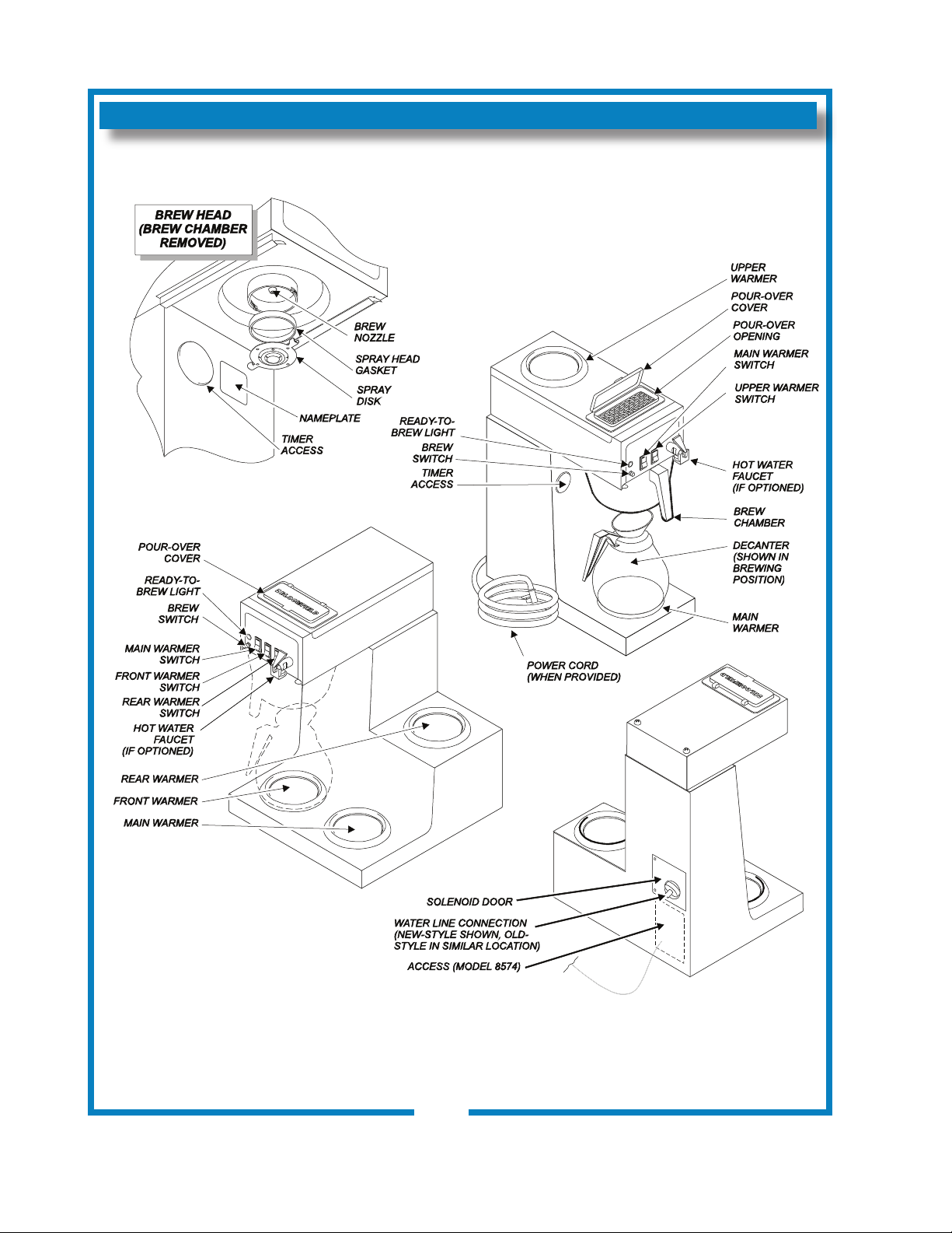
FEATURES AND OPERATING CONTROLS
IL1695
Fig. 1 Features & Operating Controls
2M-75804-611 Koffee-King 8900 Series Brewer
2
PRECAUTIONS AND GENERAL INFORMATION
WARNING
WARNING
WARNING
WARNING
WARNING: ELECTRIC SHOCK HAZARD
All servicing requiring access to non-insulated components must be performed by qualied
service personnel. Do not open any access panels which require the use of tools. Failure
to heed this warning can result in electrical shock.
WARNING: INJURY HAZARD
All installation procedures must be performed by qualied personnel with full knowledge of
all applicable electrical and plumbing codes. Failure could result in property damage and
personal injury.
WARNING: ELECTRIC SHOCK HAZARD
Brewer must be properly grounded to prevent possible shock hazard. DO NOT assume a
plumbing line will provide such a ground. Electrical shock will cause death or serious Injury.
WARNING: BURN HAZARD
This appliance dispenses very hot liquid. Serious bodily injury from scalding can occur from
contact with dispensed liquids.
This appliance is intended for commercial use only.
This appliance is intended for use to brew beverage products for
human consumption. No other use is recommended or
authorized by the manufacturer or its agents.
This appliance is intended for use in commercial establishments,
where all operators are familiar with the appliance use,
limitations and associated hazards. Operating instructions and
warnings must be read and understood by all operators and
users.
Except as noted, this piece of equipment is made in the USA
and has American sizes on hardware. All metric conversions are
approximate and can vary in size.
The following trouble shooting, component views and parts lists
are included for general reference, and are intended for use by
qualied service personnel.
This manual should be considered a permanent part of this
appliance. The manual must remain with the appliance if it is
sold or moved to another location.
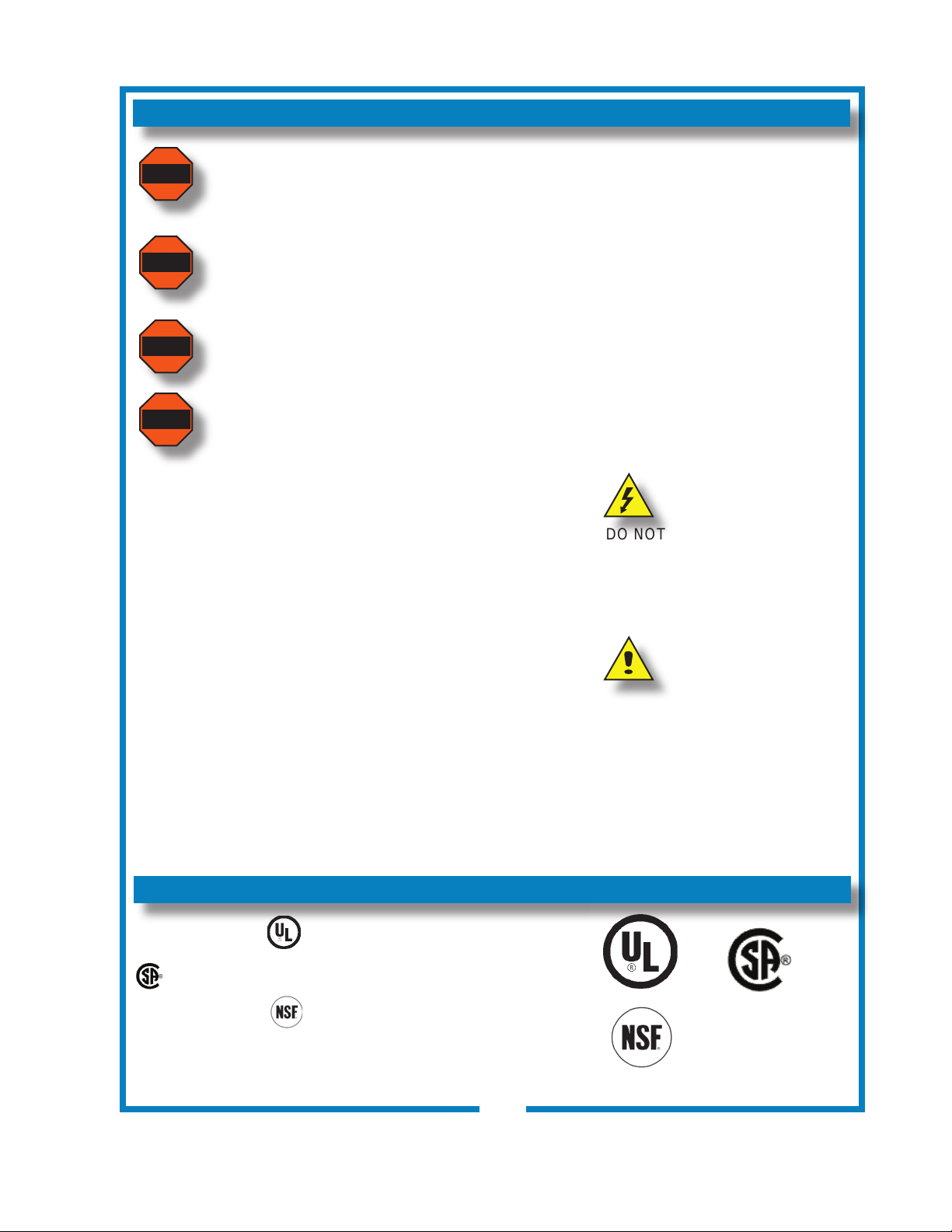
AGENCY APPROVAL INFORMATION
CAUTION:
EQUIPMENT DAMAGE
DO NOT plug in or energize this
appliance until all Installation
Instructions are read and followed.
Damage to the Brewer will occur if
these instructions are not followed.
CAUTION:
BURN HAZARD
Exposed surfaces of the
appliance, brew chamber and
decanter may be HOT to the
touch, and can cause serious
burns.
These brewer are listed under UL le E9253, and
listed under LR21315.
This brewer meets Standard 4 only when installed,
2M-75804-611 Koffee-King 8900 Series Brewer
operated and maintained in accordance with the enclosed
instructions.
E9253
STD 4
LR21315
3
INSTALLATION INSTRUCTIONS
READ THIS CAREFULLY BEFORE STARTING THE INSTALLATION
IMPORTANT:
To enable the installer to make
a quality installation and to
minimize installation time, the
following suggestions and tests
should be done before the
actual unit installation is started:
CAUTION:
EQUIPMENT DAMAGE
DO NOT plug in or energize this
appliance until all Installation
Instructions are read and
followed. Damage to the
Brewer will occur if these
instructions are not followed.
CAUTION:
UNSTABLE
EQUIPMENT HAZARD
It is very important for safety
and for proper operation that the
brewer is level and stable when
standing in its nal operating
position. Provided adjustable,
non-skid legs must be installed
at each corner of the unit.
Failure to do so will result in
movement of the brewer which
can cause personal Injury and/
or damage to brewer.
NOTE: Water supply inlet line
must meet certain minimum
criteria to insure successful
operation of the brewer.
Bloomeld recommends 1/4”
copper tubing for installation of
less than 25 feet and 3/8” for
more than 25 feet from a 1/2”
water supply line.
REFER TO EXPLODED VIEWS PAGES 18 thru 22 FOR
COMPONENT NAMES/NUMBERS
Unpack the unit. Inspect all components for completeness and
condition. Ensure that all packing materials have been removed
from the unit.
Verify that the Spray Head Gasket (#33) and Spray Disk (#34)
are properly installed.
LEVELING THE UNIT
Verify that an adjustable leg is installed at each corner of the
brewer.
Set Brewer in its operating location. Level the Brewer. A spirit
level should be placed on the top of the unit, at the edge, as a
guide when making level adjustments.
Level the unit from left to right and front to back by turning the
adjustable feet. Be sure all four feet touch the counter to prevent
tipping.
PLUMBER’S INSTALLATION INSTRUCTIONS
Brewer should be connected to a POTABLE WATER, COLD
WATER line. Flush water line before connecting to Brewer.
DO NOT use a saddle valve with a self-piercing tap for the water
line connection. Such a tap can become restricted by waterline
debris. For systems that must use a saddle tap,
main water supply and drill a 3/16” (minimum) tap for the saddle
connection, in order to insure an ample water supply. Remember
to ush the line prior to installing the saddle.
The brewer must be installed on a water line with average
pressure between 20 PSI and 90 PSI. If your water pressure
exceeds 90 PSI at anytime, a pressure regulator must be
installed in the water supply line to limit the pressure to not more
than 90 PSI in order to avoid damage to lines and solenoid.
A water shut-off valve should be installed on the incoming water
line in a convenient location (Use a low restriction type valve,
such as a 1/4-turn ball valve, to avoid loss of water ow thru the
valve.
The provided water line strainer must be installed in the supply
line, between the shutoff valve and inlet tting. Note FLOW
arrow marking on strainer body.
shut off the
2M-75804-611 Koffee-King 8900 Series Brewer
4
INSTALLATION INSTRUCTIONS (continued)
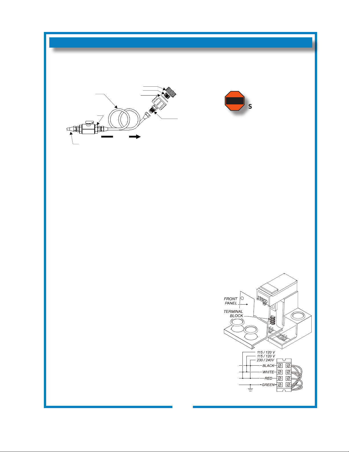
IL1652
COPPER LOOPS OR
FLEX LINES
(PROVIDED BY
PLUMBER)
SOLENOID
WATER INLET
FITTING
WATER
SUPPLY
SHUT-OFF VALVE
(PROVIDED BY
PLUMBER)
FLOW
STRAINER
WASHER
IL1696
WARNING
NSF requires that the brewer be able to be moved for cleaning
underneath. A ex line or loops of copper tubing will satisfy this
requirement. See Figure 2 below.
Fig. 2 Water Supply Installation
New-style shown
In some areas, local codes require a backow preventer
(check valve) to be installed on the inlet water line. If a backow
preventer is used, you must install a water hammer arrester
in the incoming line, between the backow preventer and the
brewer inlet, as far away from the brewer as space will allow.
This will relieve the excessive back pressures that can cause
faucet leaks and solenoid malfunctions.
ELECTRICIAN’S INSTALLATION INSTRUCTIONS
REFER TO ELECTRICAL SPECIFICATIONS - Page 1
Check the nameplate to determine correct electrical service
required for the Brewer to be installed.
IMPORTANT: Before connecting to electricity, make sure
automatic brewers are connected to the water supply.
All models (except 8574) are equipped with a cord and plug.
They require a 115 - 125 volt 20 amp circuit (50/60 Hz, 2 wire
plus ground, with NEMA 5-15R or 5-20R Receptacle).
IMPORTANT: The ground prong of the plug is part of a system
designed to protect you from electrical shock in the event of
internal damage. Never cut off the ground prong nor twist a
blade to t an existing receptacle. Contact a licensed electrician
to install the proper circuit and receptacle.
NOTE: This equipment must
be installed to comply with
applicable federal, state and
local plumbing codes and
ordinances.
WARNING:
SHOCK HAZARD
Brewer must be properly
grounded to prevent possible
shock hazard. DO NOT
assume a plumbing line will
provide such a ground.
Electrical shock will cause death
or serious injury.
IMPORTANT: Do not connect
brewer to electrical power until
the tank is lled with water.
Pour water into the pour-over
opening until water ows from
the brew head.
IMPORTANT:
Supply power must match
nameplate for voltage and
phase. Connecting to the
wrong voltage will damage the
brewer or result in decreased
performance. Such damage is
not covered by warranty.
2M-75804-611 Koffee-King 8900 Series Brewer
Model 8574 must be wired by an electrician, and requires a
115/230V 20A circuit (50/60 Hz, 2 hot legs / 1 neutral leg, plus
ground). Remove front panel to gain access to terminal block.
Green terminal must be connected to a suitable building ground.
Circuit must be capable of 3800 Watts. See gure 3 at right.
IMPORTANT: Wiring must be installed in approved solid or
exible conduit, and must be secured to the brewer with a strain
relief (to be provided by the installer).
5
Fig. 3 115/240 Volt Terminal Block
OPERATION
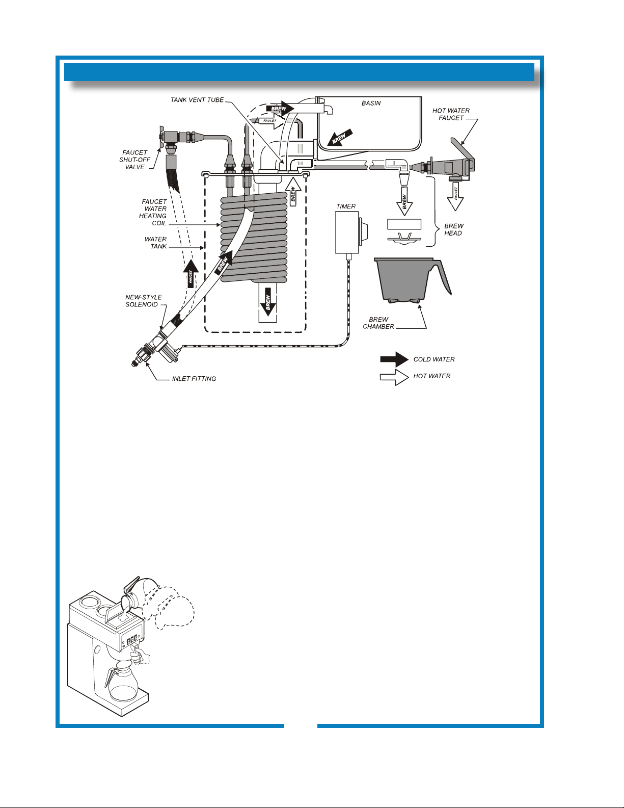
IL1697
IL1618
Fig. 4 Brewer Operation Diagram
IMPORTANT:
Tank must be full of
water before connecting
brewer to electrical power.
A.
For initial start-up, or if the brewer has not been used for an
extended period of time:
Heating elements will be
damaged if allowed to
operate without being fully
submerged in water.
Damage caused by
operating the brewer
without water in the tank
is NOT COVERED BY
WaRRaNTY.
BEFORE plugging the brewer into a receptacle, or otherwise
connecting brewer to electrical power ThE WaTER TaNK MuST
BE FIllED. Place an empty decanter under the brew head. Lift
the pour-over cover then pour warm tap water into the pour-over
opening until water ows from the brew head. When water stops
dripping from the brew head, empty the container.
Once the tank is full of water, connect the brewer to electrical
power. The heating elements will begin heating the water in the
tank. When the water has reached the proper temperature, the
“READY To BREW” light will glow.
START-UP
•
Be sure spray disk and brew gasket are properly installed in the
brew head.
• Be sure the water supply is properly connected and the water
supply valve is turned ON.
• Be sure the WATER TANK IS FILLED
2M-75804-611 Koffee-King 8900 Series Brewer
6
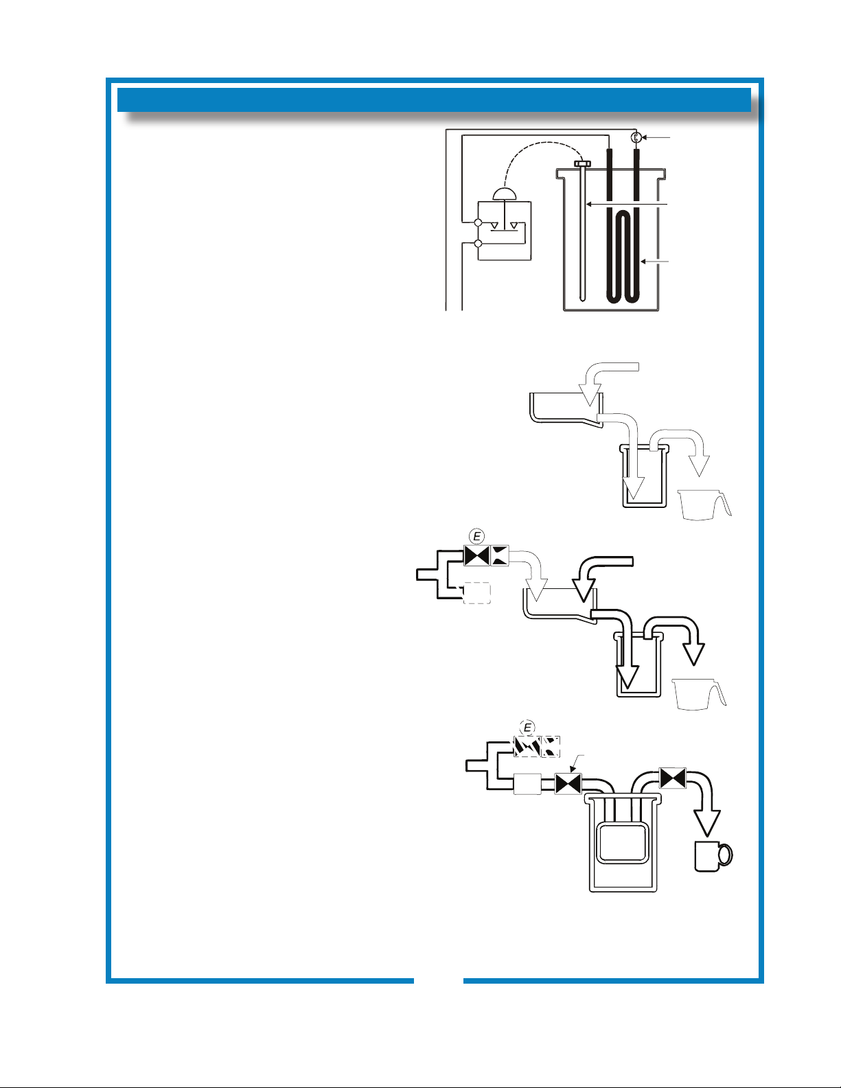
IL1654
HI-LIMIT
THERMOSTAT
THERMOBULB
HEATER
ELEMENT
MANUAL
POUR-OVER
MANUAL
POUR-OVER
BASIN
PAN
BASIN
PAN
FAUCET
SHUT-OFF
VALVE
FAUCET
BYPASS
FAUCET
BYPASS
SOLENOID
SOLENOID
FAUCET
TANK
WATER
COIL
HOT
WATER
BREW
BREW
TANK
TANK
THERMOSTAT
OPERATION (continued)
WATER HEATER
Water temperature is sensed by a
thermobulb inserted into the water tank. This
temperature signal is fed to the thermostat,
which controls line power to the heating
element.
The setpoint temperature is adjustable at the
thermostat.
The element is protected from overtemperature by a hi-limit thermostat.
WATER FLOW
POUR-OVER FEATURE
Pouring any amount of cold water into the
pour-over opening and into the basin pan
forces an identical amount of hot water out
of the tank and through the spray head into
the brew chamber.
AUTOMATIC OPERATION
Pressing BREW button energizes the
solenoid valve, allowing water from an
external water supply to ow into the basin
pan and then into the hot water tank. This
forces an identical amount of hot water out
of the tank and through the spray head into
the brew chamber
The solenoid uses a ow control device so
that ow is consistent between 20 p.s.i. and
90 p.s.i.
Length of time the solenoid is open is
controlled by the timer.
Fig. 5 heat Control Diagram
HOT WATER FAUCET
The faucet water coil is submerged in the
hot water tank and draws heat from the brew
water. Water going to the water coil is not
controlled by the solenoid valve.
The faucet is at supply water pressure any
time the faucet shut-off valve is OPEN.
2M-75804-611 Koffee-King 8900 Series Brewer
Fig. 6 Water Flow Diagram
7
 Loading...