


 Loading...
Stock No.
6384B
User Manual
Single Channel MPEG-2 HD Encoder
HDE-CHV-QAM/IP
1xComponent/HDMI/VGA/Composite Inputs 1xQAM + 1xIP Outputs
v20180509
Status |
Date |
Document No. |
Issue No. |
Author |
|
|
|
|
|
ACTIVE |
June 28, 2017 |
651238300B |
2 |
KK |
|
|
|
|
|
OBSOLETE |
April 26, 2016 |
651238300A |
1 |
MB |
|
|
|
|
|
800-523-6049
www.blondertongue.com
Blonder Tongue is ISO 9001:2015 Certified
©2018 Blonder Tongue Laboratories, Inc. All rights reserved. Specifications are subject to change without notice. Trademarks are the property of their respective owner.

2HDE-CHV-QAM/IP
Instruction Manual
We recommend that you write the following information in the spaces provided below.
Purchase Location Name:
Purchase Location Telephone Number:
HDE-CSV-QAM/IP Serial Number:
The information contained herein is subject to change without notice. Revisions may be issued to advise of such changes and/or additions.
Correspondence regarding this publication should be addressed directly to:
Blonder Tongue Laboratories, Inc. One Jake Brown Road
Old Bridge, NJ 08857 USA Document Number: 651238300B
Printed in the United States of America.
All product names, trade names, or corporate names mentioned in this document are acknowledged to be the proprietary property of the registered owners.
This product incorporates copyright protection technology that is protected by U.S. patents and other intellectual property rights. Reverse engineering or disassembly is prohibited.
Cross-Reference & Hyperlinking Usage
This guide makes use of hyperlinks for the Table of Contents, some cross-reference linking between sections, and external hyperlinking to web addresses. This has been done to assist the reader in finding the information they are seeking in a much quicker way. In addition to hyperlinking, the Table of Contents also makes use of the bookmarking feature present in the Adobe Reader application.
Product and Documentation Updates
DownloadthelatestUserManual(PDF)byvisitingourwebsite.NavigatetotheproductpagebyenteringthefullModel Name or Stock Number in the search field. Upon reaching the product page, the “User Manual” download link will be located beneath the product image. Firmware Updates are available under “Tech Support” in the “Resources” section of the website. General instructions for the FTP site, as well as updating your firmware, are provided on this page.
Returning Product for Repair (or Credit)
AReturnMaterialAuthorization(RMA)NumberisrequiredonallproductsreturnedtoBlonderTongue,regardlessif theproductisbeingreturnedforrepairorcredit.Before returning product, please contact the Blonder Tongue Service Department at 1-800-523-6049, Ext. 4256 or visit our website: www.blondertongue.com for further information.

|
HDE-CHV-QAM/IP 3 |
|
Instruction Manual |
Table of Contents |
|
SECTION 1- GENERAL & SAFETY INSTRUCTIONS ........................................................................................................ |
4 |
SECTION 2- PRODUCT SUMMARY............................................................................................................................... |
5 |
2.1 REVISION HISTORY & REASON................................................................................................................................... |
5 |
2.2 PRODUCT APPLICATION & DESCRIPTION................................................................................................................... |
5 |
2.3 PRODUCT SPECIFICATION........................................................................................................................................... |
8 |
SECTION 3- INSTALLATION & POWER-UP.................................................................................................................... |
9 |
3.1 UNPACKING................................................................................................................................................................ |
9 |
3.2 INSTALLATION............................................................................................................................................................. |
9 |
3.3 POWER-UP.................................................................................................................................................................. |
9 |
SECTION 4- COMMUNICATING WITH THE UNIT........................................................................................................ |
10 |
SECTION 5- CONFIGURING THE UNIT......................................................................................................................... |
11 |
5.1 ACCESSING THE UNIT VIA THE WEB BROWSER........................................................................................................ |
11 |
5.2 “MAIN > STATUS” SCREEN......................................................................................................................................... |
12 |
5.3 “MAIN > VIDEO” SCREEN ......................................................................................................................................... |
12 |
5.4 “MAIN > AUDIO” SCREEN.......................................................................................................................................... |
13 |
5.5 “MAIN > TS CONFIG” SCREEN.................................................................................................................................. |
15 |
5.6 “MAIN > IP” SCREEN ................................................................................................................................................ |
16 |
5.7 “MAIN > QAM” SCREEN ........................................................................................................................................... |
17 |
5.8 “MAIN > OUTPUT” SCREEN ..................................................................................................................................... |
18 |
5.9 “MAIN > REFRESH” TAB............................................................................................................................................. |
19 |
5.10 “NETWORK” SCREEN............................................................................................................................................... |
19 |
5.11 “TIME” SCREEN....................................................................................................................................................... |
20 |
5.12 “EVENT LOG” SCREEN............................................................................................................................................. |
21 |
5.13 “ADMIN” SCREEN.................................................................................................................................................... |
22 |
APPENDIX A: VIEWING THE IP OUTPUT ON A VLC MEDIA PLAYER ........................................................................... |
25 |
4HDE-CHV-QAM/IP
Instruction Manual
Section 1 - General & Safety Instructions
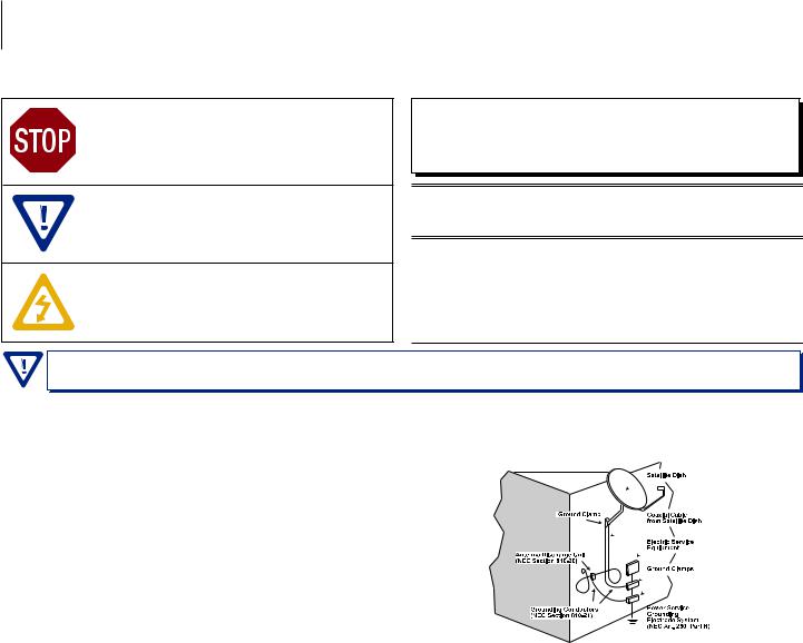
The STOP sign symbol is intended to alert you to the presence of REQUIRED operating and maintenance (servicing)instructionsthatifnotfollowed,mayresultin productfailureordestruction.
The YIELD sign symbol is intended to alert you to the presenceofRECOMMENDEDoperatingandmaintenance (servicing)instructions.
The LIGHTNING flash symbol is intended to alert you to the presence of uninsulated “dangerous voltage” within the product's enclosure that may be of sufficient magnitudetoconstituteariskofelectricalshock.
TOREDUCETHERISKOFELECTRICALSHOCK,DONOTREMOVECOVER
FROMTHISUNIT.
NOUSER-SERVICEABLEPARTSINSIDE.REFERSERVICINGTOQUALIFIED
SERVICEPERSONNEL.
WARNING:TOPREVENTFIREORSHOCKHAZARD,DONOTEXPOSETHIS
UNITTORAINORMOISTURE
NOTE TO CATV SYSTEM INSTALLER
ThisreminderisprovidedtocalltheCATVSystemInstaller’sattentionto Article 820-40 of the NEC that provides guidelines for proper grounding and, in particular, specifies that the cable ground shall be connected to thegroundingsystemofthebuilding,asclosetothepointofcableentry aspractical.
You should always follow these Instructions to help ensure Against injury to yourself and damage to your equipment.
åå Elevated Operating Ambient - If installed in a closed or multi-unit rack assembly, the operating ambient temperature of the rack environment may be greater than room ambient. Therefore, consideration should be given to installing the equipment in an environment compatible with the maximum ambient temperature per Section 2.3.
åå Reduced Air Flow - Installation of the equipment in a rack should be such that the amount of air flow required for safe operation of the equipment is not compromised.
åå Mechanical Loading - Mounting of the equipment in the rack should be such that a hazardous condition is not achieved due to uneven mechanical loading.
åå Circuit Overloading - Consideration should be given to the connection of the equipment to the supply circuit and the effect that overloading of the circuits might have on overcurrent protection and supply wiring. Appropriate consideration of equipment nameplate ratings should be used when addressing this concern.
åå Reliable Earthing - Reliable earthing of rack-mounted equipment should be maintained. Particular attention should be given to supply connections other than direct connections to the branch circuit (e.g. use of power strips).
åå Read all safety and operating instructions before you operate the unit. åå Retain all safety and operating instructions for future reference.
åå Heed all warnings on the unit and in the safety and operating instructions. åå Follow all installation, operating, and use instructions.
åå Unplug the unit from the AC power outlet before cleaning. Use only a damp cloth for cleaning the exterior of the unit.
åå Do not use accessories or attachments not recommended by Blonder Tongue, as they may cause hazards, and will void the warranty.
åå Do not operate the unit in high-humidity areas, or expose it to water or moisture.
åå Do not place the unit on an unstable cart, stand, tripod, bracket, or table. The unitmayfall,causingseriouspersonalinjuryanddamagetotheunit.Installthe unitonlyinamountingrackdesignedfor19”rack-mountedequipment.
åå Do not block or cover slots and openings in the unit. These are provided for ventilationandprotectionfromoverheating. Neverplacetheunitnearorover a radiator or heat register. Do not place the unit in an enclosure such as a cabinet without proper ventilation. Do not mount equipment in the rack space directly above or below the unit.
åå Operate the unit using only the type of power source indicated on the marking label. Unplug the unit power cord by gripping the plug, not the cord.
åå The unit is equipped with a three-wire ground-type plug. This plug will fit only into a ground-type power outlet. If you are unable to insert the plug into the outlet, contact an electrician to replace the outlet. Do not defeat the safety purpose of the ground-type plug.
åå Route power supply cords so that they are not likely to be walked on or pinched by items placed upon or against them. Pay particular attention to cords at plugs, convenience receptacles, and the point where they exit from the unit.
åå Be sure that the outdoor components of the antenna system are grounded in accordancewithlocal,federal,andNationalElectricalCode(NEC)requirements. Pay special attention to NEC Sections 810 and 820. See the example shown in the following diagram:
åå We strongly recommend using an outlet that contains surge suppression or ground fault protection. For added protection during a lightning storm, or when the unit is left unattended and unused for long periods of time, unplug it from the wall outlet and disconnect the lines between the unit and the antenna. This will prevent damage caused by lightning or power line surges.
åå Do not locate the antenna near overhead power lines or other electric light or power circuits, or where it can fall into such power lines or circuits. When installing the antenna, take extreme care to avoid touching such power lines or circuits, as contact with them can be fatal.
åå Do not overload wall outlets or extension cords, as this can result in a risk of fire or electrical shock.
åå Never insert objects of any kind into the unit through openings, as the objects may touch dangerous voltage points or short out parts. This could cause fire or electrical shock.
åå Do not attempt to service the unit yourself, as opening or removing covers may expose you to dangerous voltage and will void the warranty. Refer all servicing to authorized service personnel.
åå Unplug the unit from the wall outlet and refer servicing to authorized service personnel whenever the following occurs:
oo The power supply cord or plug is damaged;
oo Liquidhasbeenspilled,orobjectshavefallenintotheunit; oo The unit has been exposed to rain or water;
oo The unit has been dropped or the chassis has been damaged; oo The unit exhibits a distinct change in performance.
åå When replacement parts are required, ensure that the service technician uses replacement parts specified by Blonder Tongue. Unauthorized substitutions may damage the unit or cause electrical shock or fire, and will void the warranty.
åå Upon completion of any service or repair to the unit, ask the service technician to perform safety checks to ensure that the unit is in proper operating condition.

HDE-CHV-QAM/IP 5
Instruction Manual
Section 2 - Product Summary
2.1 Revision History & Reason
Issue 2: Manual adds support for custom video and transport stream bit rate settings on v1.2.0.0.
Issue 1: Instruction Manual for HDE-CHV-QAM/IP, a new unit that replaces the HDE-CHV-QAM (#6384A).
2.2 Product Application & Description
Application:
The HDE-CHV-QAM/IP accepts one HD program from any of the following inputs: 1xComponent, 1xHDMI (unencrypted), 1xVGA, and 1xComposite. The MPEG-2 encoded outputs are available in 1xQAM and 1xIP (100/1000Base-T Ethernet).
The 1xQAM RF output is frequency agile over the entire CATV frequency range of 5-1002 MHz, including sub channels T7-
T14, and 2-158, with an output level of +40 dBmV.
Comprehensive remote monitoring and control is accomplished using any standard Web browser via a front-panel 100/1000
Ethernet connection. A rear-panel VGA output port is available for loop-through applications.
Features:
•Accepts one (1) program from any of the following inputs: 1xComponent, 1xHDMI (unencrypted), 1xVGA, and 1xComposite
•Simultaneously delivers 1xQAM and 1xIP outputs
•Provides +40 dBmV QAM RF output level
•Provides full QAM output coverage from 5 to 1002 MHz (sub channels T7-T14, and 2-158)
•Supports custom video and transport stream bit rate settings
•Supports user-defined PSIP configuration
•Supports Real-time Dolby® Digital audio encoding
•Supports Closed Captioning EIA-608
•Provides comprehensive GUI-based monitoring and control via standard
•Compact design permits installation of up to 3 Encoder modules in 1RU
6HDE-CHV-QAM/IP
Instruction Manual
Description:
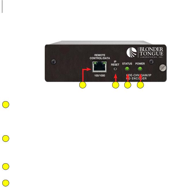
Front Panel connectors and indicators:
3 |
4 |
1 |
2 |
1 STATUS LED: LED indicates the status of input video and audio as follows:
LED is Green = Both Video and Digital Audio inputs are present.
LED is Red = Either the Video or Digital Audio is not present, or internal temperature is too high.
Note: The encoder does not sense analog audio inputs. Therefore, if the Audio is set for Analog, the status indicator will only be valid for video.
2 POWER:
LED is Green = AC power is detected.
LED is Off = indicates (i) AC power is not connected, or (ii) AC power is connected but the power supply or encoder is defective. The unit must be sent to Blonder Tongue for repair for condition (ii).
3 REMOTE CONTROL/DATA 100/1000: RJ45 connector for 100/1000Base-T Ethernet interface for monitoring and configuring the unit. The same interface is also used to deliver the IP output. Only static IP address can be assigned to this interface. (Factory Default: “172.16.70.1”)
4IP RESET BUTTON: When pressed for >10 seconds, the IP address of the control port will be enabled to the default factory IP address (172.16.70.1, Subnet Mask 255.255.0.0). The login credentials will also be enabled to the default username Admin and password pass.
Note: The old IP address, login, and password will still be present in the encoder settings. To clear the reset mode simply reboot the encoder.

Rear panel connectors:
5 |
6 |
9 |
10 |
11 |
HDE-CHV-QAM/IP 7
Instruction Manual
7 |
8 |
12 |
5QAM RF OUTPUT: “F” connector for QAM output.
6VGA OUTPUT: DE-15 female connector for loop-through VGA output.
7AUDIO: RCAconnectors(markedLandR)forAnalogLeft/RightAudioinputandRCAconnector(marked“DIGITAL”)for
Digital Audio program input.
8CC: RCAconnector(marked“CC”)forAnalogNTSCClosedCaptioning(EIA-608,alsoknownasLine21),whichwillthen be digitized and inserted in the MPEG-2 Transport Stream of the Component, HDMI, and VGA inputs.
9 INPUT POWER: ITE power supply - rated 120VAC; 60 Hz / Output 12VDC ; 3A 10 HDMI: HDMI connector for unencrypted HDMI input.
THE UNIT DOES NOT ACCEPT HDCP-ENCRYPTED HDMI INPUT.
11VGA INPUT: DE-15 female connector for VGA input.
12COMPONENT: RCA connectors (marked Pr, Pb, Y) for Analog Component Video input. The RCA connector (marked Y) is also used for Composite Video input.

8HDE-CHV-QAM/IP
Instruction Manual
2.3Product Specification
Input
Component
Connectors:
Video Resolution:
Video Aspect Ratio:
Audio:
HDMI
Connector:
Video Resolution:
HDCP Encryption:
Audio:
VGA
Connectors:
Video Resolution:
Audio:
Composite
Connectors:
Video Resolution:
Audio:
3x RCA for Video (Y, Pb, Pr) 480i, 720p, & 1080i
4:3 & 16:9
2x RCA for Analog Audio (L, R)
1x RCA for Digital Audio (PCM and Dolby® Digital pass-through only)
1x HDMI
480i, 720p, & 1080i Not supported
Embedded PCM and Dolby® Digital pass-through only
2x Female VGA (Input + Loop-through Output)
640x480 @ 60 fps
800x600 @ 60 fps
1024x768 @ 60 fps
2x RCA for Analog Audio (L, R)
1x RCA for Digital Audio (PCM and Dolby® Digital pass-through only)
1x RCA for Video (Y)
480i
2x RCA for Analog Audio (L, R)
1x RCA for Digital Audio (PCM and Dolby® Digital pass-through only)
Encoding Profile
Video
Output Format: Chroma:
Resolution: Frame rate:
Aspect Ratio:
GOP Structure:
Video Bit Rate:
Video Pre-filter: Color Space:
Audio
Output Format: Sampling rate:
Bit rate:
Closed Captioning
Component:
HDMI:
VGA:
Composite:
MPEG-2 HD MP@ML; ISO 13818-2 4:2:0
480i, 720p, & 1080i
29.97 fps (480i); 29.97 fps (1080i); 59.97 fps (720p) 4:3 & 16:9
I & P frames (user-selectable) Variable (user-selectable) Variable (user-selectable)
YCbCr and RGB
Dolby® Digital 48 kHz
Variable; 96 - 448 Kbps (user-selectable)
EIA-608; 1x RCA (CC)
EIA-608; 1x RCA (CC)
EIA-608; 1x RCA (CC)
EIA-608
Output
QAM
Connector:
Modulation:
Standards:
DVB Symbol Rate:
Frequency Range:
Tuning:
Channels’ Bandwidth:
RF Level:
RF Level Adjustment:
Frequency Tolerance:
Frequency Stability:
Amplitude Flatness:
Phase Noise:
Spurious:
Broadband Noise:
Impedance:
Spectral Inversion:
Carrier Suppression:
Return Loss:
Signal-to-Noise Ratio (SNR):
MER:
I/Q Phase Error:
I/Q Amplitude Imbalance:
IP
Connector:
Standard:
TS Bit Rate:
UDP/RTP:
1x “F” Female (Rear-panel)
QAM 16, 32, 64, 128, and 256 ITU-T J.83; Annex A and B
Variable; up to 7 MSymbol/sec (MBaud) 5 to 1002 MHz
CATV Channel Selectable (Ch. T7 to T14, 2 to 158) 6 MHz
+40 dBmV ±1 dB
+35 to +42 dBmV, 1 dB increment
±0.5 kHz @ 77 °F (25 °C)
±5 kHz over 32 to 122 °F (0 to 50 °C)
±0.25 dB (over 6 MHz channel)
-98 dBc (@ 10 kHz)
-60 dBc
-70 dBc (@ +40 dBmV output level, 5.5 MHz bandwidth)
75 Ω
Auto Recognition 45 dB
14 dB typical
40 dB typical
40 dB typical
Less than 1 degree Less than 1%
1x RJ45 (Front-panel)
100/1000Base-T Ethernet Variable (user-selectable) Supported (user-selectable)
General
Dimensions (W x D x H):
Power:
Power Dissipation:
Weight (one module):
Operating Temperature:
Storage Temperature:
Operating Humidity:
Storage Humidity:
5.65 x 14.10 x 1.72 inches (143.5 x 358.1 x 43.7 mm)
External Power Supply
(Input 120 VAC; 60Hz / Output 12 VDC @ 3 Amps)
16 W
1.75 lbs (0.795 kg)
32 to 122 °F (0 to 50 °C)
-13 to 158 °F (-25 to 70 °C)
0 to 95% RH @ 35 °C max, non-condensing
0 to 95% RH @ 35 °C max, non-condensing
Alarms/Monitoring/Control
Local Monitoring: 1x Power LED 1x Status LED
Local Control: 1x IP Reset button
Remote GUI-based menu via stantard Web browser
Monitoring/Control: (1x RJ45 front-panel connector; 100/1000Base-T, also used for IP output)

HDE-CHV-QAM/IP 9
Instruction Manual
Section 3 - Installation & Power-up
3.1 Unpacking
You will find the following items in the box:
•HDE-CHV-QAM/IP Encoder (QTY=1)
•Switching Mode Power Supply, 12 VDC, 3.0A (Item: 515132200)
•A hardware bag (item 741021800) containing the following:
Seven-foot cross-pinned (cross-over) RJ45 Ethernet cable (QTY=1)
3.2 Installation
The HDE-CHV-QAM/IP encoder is designed to be installed in the HDE-3MCH Series rack chassis. The chassis can support 3 encoder modules, each utilizing 2 standard single slots.
You can mount the chassis in a standard EIA, 24 inch (610 mm) deep, enclosed rack. Secure the rack chassis front panel to the rack by inserting four machine screws, with cup washers, through the four mounting holes in the front panel.
Wheninstallingoneormorechassisinaheadendrack,itisrecommendedtoleavea1rackunitspace(1.75”high)between units to maximize air flow, but it is not required.
FOR SAFE AND RELIABLE OPERATION, THE GROUND PIN OF THE POWER CORD PLUG MUST BE GROUNDED PROPERLY 

3.3 Power-up
To power up the unit, connect the line cord to a 120 VAC outlet.
The “POWER” LED on the front-panel will light green.
Loading...