

Page 1

SBC-G Series
GAS BOILERLESS STEAMER
INSTALLATION - OPERATION - MAINTENANCE
BLODGETT OVEN COMPANY
www.blodgett.com
44 Lakeside Avenue, Burlington, Vermont 05401 USA
Manufacture Service Questions: 866-518-3977
PART NUMBER 170209 REV A (04/11)
Page 2

THIS MANUAL MUST BE RETAINED FOR FUTURE REFERENCE. READ, UNDERSTAND
AND FOLLOW THE INSTRUCTIONS AND WARNINGS CONTAINED IN THIS MANUAL.
FOR YOUR SAFETY
DO NOT STORE OR USE GASOLINE OR OTHER FLAMMABLE VAPORS AND LIQUIDS IN
THE VICINITY OF THIS OR ANY OTHER APPLIANCE.
POST IN A PROMINENT LOCATION
INSTRUCTIONS TO BE FOLLOWED IN THE EVENT USER SMELLS GAS. THIS INFORMATION
SHALL BE OBTAINED BY CONSULTING YOUR LOCAL GAS SUPPLIER. AS A MINIMUM,
TURN OFF THE GAS AND CALL YOUR GAS COMPANY AND YOUR AUTHORIZED SERVICE
AGENT. EVACUATE ALL PERSONNEL FROM THE AREA.
WARNING
IMPROPER INSTALLATION, ADJUSTMENT, ALTERATION, SERVICE OR MAINTENANCE CAN
CAUSE PROPERTY DAMAGE, INJURY OR DEATH. READ THE INSTALLATION, OPERATING
AND MAINTENANCE INSTRUCTIONS THOROUGHLY BEFORE INSTALLING OR SERVICING
THIS EQUIPMENT.
NOTIFY CARRIER OF DAMAGE AT ONCE
IT IS THE RESPONSIBILITY OF THE CONSIGNEE TO INSPECT THE CONTAINER UPON
RECEIPT OF SAME AND TO DETERMINE THE POSSIBILITY OF ANY DAMAGE, INCLUDING
CONCEALED DAMAGE. WE SUGGEST THAT IF YOU ARE SUSPICIOUS OF DAMAGE TO
MAKE A NOTATION ON THE DELIVERY RECEIPT. IT WILL BE THE RESPONSIBILITY OF THE
CONSIGNEE TO FILE A CLAIM WITH THE CARRIER. WE RECOMMEND THAT YOU DO SO
AT ONCE.
Page 3

IMPORTANT - READ FIRST - IMPORTANT
WARNING: THE UNIT MUST BE INSTALLED BY PERSONNEL QUALIFIED TO WORK WITH ELECTRICITY AND PLUMBING.
IMPROPER INSTALLATION CAN CAUSE INJURY TO PERSONNEL AND/OR DAMAGE TO THE EQUIPMENT.
THE UNIT MUST BE INSTALLED IN ACCORDANCE WITH APPLICABLE CODES.
CAUTION: SHIPPING STRAPS ARE UNDER TENSION AND CAN SNAP BACK WHEN CUT.
CAUTION: DO NOT INSTALL THE UNIT IN ANY WAY WHICH WILL BLOCK THE REAR VENTS, OR WITHIN 2 INCHES OF A
HEAT SOURCE SUCH AS A BRAISING PAN, DEEP FRYER, CHAR BROILER OR KETTLE.
CAUTION: LEVEL THE UNIT FRONT TO BACK, AND PITCH IT SLIGHTLY TO THE FRONT, TO AVOID DRAINAGE
PROBLEMS.
WARNING: FOLLOW THE WIRING DIAGRAM EXACTLY WHEN CONNECTING A UNIT TO AVOID DAMAGE OR INJURY.
WIRING DIAGRAM IS LOCATED ON THE INSIDE OF THE RIGHT PANEL.
CAUTION: DO NOT USE PLASTIC PIPE. DRAIN MUST BE RATED FOR BOILING WATER.
WARNING: DO NOT CONNECT THE DRAIN DIRECTLY TO A BUILDING DRAIN.
WARNING: BLOCKING THE DRAIN IS HAZARDOUS.
IMPORTANT: IMPROPER DRAIN CONNECTION WILL VOID WARRANTY.
IMPORTANT: DO NOT ALLOW ANY WATER TRAPS IN THE DRAIN LINE. A TRAP CAN CAUSE PRESSURE TO BUILD UP
INSIDE THE CAVITY DURING STEAMING, WHICH WILL MAKE THE DOOR GASKET LEAK.
WARNING:
WARNING: BEFORE CLEANING THE OUTSIDE OF THE STEAMER, DISCONNECT THE ELECTRIC POWER SUPPLY. KEEP
WARNING: ALLOW COOKING CHAMBER TO COOL COMPLETELY BEFORE CLEANING.
WARNING: USE MILD CLEANING AGENTS ONLY. CAREFULLY READ THE WARNINGS AND FOLLOW THE DIRECTIONS
WARNING: DO NOT PUT HANDS OR TOOLS INTO THE COOKING CHAMBER UNTIL THE FAN HAS STOPPED TURNING.
WARNING: DO NOT OPERATE THE UNIT UNLESS THE REMOVABLE RIGHT SIDE PANEL HAS BEEN RETURNED TO ITS
NOTICE: DO NOT USE A CLEANING AGENT THAT CONTAINS ANY SULFAMIC ACID, OR ANY CHLORIDE, INCLUDING
NOTICE: DO NOT USE ANY DEGREASER THAT CONTAINS POTASSIUM HYDROXIDE OR SODIUM HYDROXIDE OR
WHEN YOU OPEN THE DOOR, STAY AWAY FROM STEAM COMING OUT OF THE UNIT. STEAM CAN CAUSE BURNS.
WATER AND CLEANING SOLUTIONS OUT OF CONTROLS AND ELECTRICAL COMPONENTS. NEVER HOSE
OR STEAM CLEAN ANY PART OF THE UNIT.
ON THE LABEL OF EACH CLEANING AGENT. USE SAFETY GLASSES AND RUBBER GLOVES AS
RECOMMENDED BY CLEANING AGENT MANUFACTURER.
PROPER LOCATION.
HYDROCHLORIC ACID. IF THE CHLORIDE CONTENT OF ANY PRODUCT IS UNCLEAR, CONSULT THE
MANUFACTURER. DO NOT USE A CLEANING OR DELIMING AGENT THAT CONTAINS MORE THAN 30%
PHOSPHORIC ACID.
THAT IS ALKALINE.
WARNING: USE OF ANY REPLACEMENT PARTS OTHER THAN THOSE SUPPLIED BY THE MANUFACTURER OR
AN AUTHORIZED DISTRIBUTOR VOIDS ALL WARRANTIES AND CAN RESULT IN BODILY INJURY TO
THE OPERATOR AND DAMAGE THE EQUIPMENT. SERVICE BY OTHER THAN FACTORY-AUTHORIZED
PERSONNEL WILL VOID ALL WARRANTIES.
WARNING: HIGH VOLTAGE EXISTS INSIDE CONTROL COMPARTMENTS. DISCONNECT FROM BRANCH CIRCUIT
BEFORE SERVICING. FAILURE TO DO SO CAN RESULT IN INJURY OR DEATH.
OM-SBC-G 1
Page 4

Table of Contents
Important Operator Warnings .........................................................page 1
References.................................................................................... page 2
Equipment Description................................................................... page 3
Inspection and Unpacking ............................................................ page 4
Installation .................................................................................. page 5-7
Initial Start-Up................................................................................ page 8
Operation .................................................................................. page 9-10
Cleaning.................................................................................. page 11-12
Maintenance................................................................................. page 13
Troubleshooting............................................................................ page 14
Schematics/Wiring Diagram ........................................................ page 19
Service Log .................................................................................. page 20
References
UNDERWRITERS LABORATORIES, INC.
333 Pngsten Road
Northbrook, Illinois 60062
NFPA/70 - The National Electrical Code
NFPA/54 - The National Fuel Gas Code
NATIONAL FIRE PROTECTION ASSOCIATION
60 Battery March Park
Quincy, Massachusetts 02269
NSF INTERNATIONAL
789 N. Dixboro Road
P.O. Box 130140
Ann Arbor, Michigan 48113-0140
2 OM-SBC-G
Page 5
Equipment Description
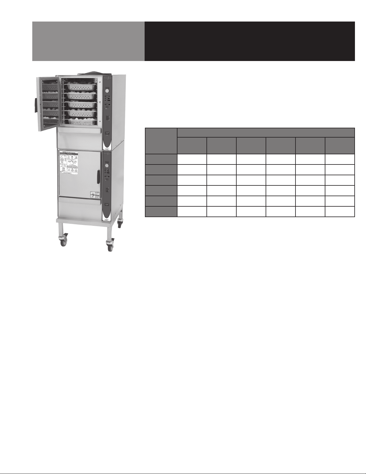
Your 3-pan, 5-pan or 10-pan boilerless steamer is designed to give years of service.
It has a stainless steel cavity (cooking chamber) which is served by an gas heated
atmospheric steam generating reservoir. A powerful blower circulates the steam in the
cavity to increase heating efficiency.
Each cavity holds up to three, five or ten steam table pans (12” x 20” x 21/2” deep) as
shown below.
PAN DIMENSIONS
Model
12 x 20 x 1
12 x 20 x
2-1/2
12 x 20 x 4 12 x 20 x 6 13 x 18 x 1 26 x 18 x 1
3-Pan
(2) 3-Pan
5-Pan
(2) 5-Pan
10-Pan
(2) 10-Pan
6 3 2 1 - -
12 6 4 2 - -
10 5 3 2 - -
20 10 6 4 - -
20 10 6 4 20 10
40 20 12 8 40 20
An 18-guage stainless steel case encloses the cavity, the steam generating reservoir
and the control compartment that houses electrical components. Door hinges are
field-reversible (the door may be set to open from the left or right). Operating controls
are on the front panel.
The boilerless steamers are equipped with fully electronic controls. These units are
readily identified by their unique control panels. Steamer function is controlled by
touch pad controls and a rotary timer-dial. The drain system on all models includes a
spray condenser, which cools drain water.
OM-SBC-G 3
Page 6

Inspection & Unpacking
CAUTION
SHIPPING STRAPS ARE UNDER TENSION
AND CAN SNAP BACK WHEN CUT.
Your boilerless steamer will be delivered completely assembled in a heavy shipping
carton strapped to a skid. On receipt, inspect carton carefully for exterior damage.
Carefully cut the straps and detach the sides of the carton from the skid. Pull the carton
up off the unit. Be careful to avoid personal injury or equipment damage from staples
which might be left in the carton walls. Write down the model number, serial number and
installation date. Keep this information for reference. Space for these entries is provided
at the top of the Service Log in the back of this manual.
Steamer Type Ship Weight (LBS) Ship Weight (KGS)
3-Pan Table Top
3-Pan on stand
(2) 3-Pan on stand
5-Pan table top
5-Pan on stand
(2) 5-Pan on stand
10-Pan on stand
(2) 10-Pan on stand
240 109
310 141
475 215
272 123
345 156
555 252
452 205
764 347
When starting installation, check packing materials to make sure loose parts such as the
condensate drip tray are not discarded with this material.
4 OM-SBC-G
Page 7
Installation
WARNING
THE UNIT MUST BE INSTALLED BY
PERSONNEL WHO ARE QUALIFIED TO
WORK WITH ELECTRICITY AND PLUMBING.
IMPROPER INSTALLATION CAN CAUSE
INJURY TO PERSONNEL AND/OR DAMAGE TO
THE EQUIPMENT. THE UNIT MUST BE
INSTALLED IN ACCORDANCE WITH
APPLICABLE CODES.
CAUTION
DO NOT INSTALL THE UNIT WITH THE REAR
VENTS BLOCKED OR WITHIN 2 INCHES
OF A HEAT SOURCE SUCH AS A BRAISING
PAN, DEEP FAT FRYER, CHARBROILER OR
KETTLE. TO AVOID DRAINAGE PROBLEMS,
LEVEL THE UNIT FRONT TO BACK, AND
PITCH SLIGHTLY TO THE FRONT.
WARNING
THE AREA DIRECTLY AROUND THE
APPLIANCE MUST BE CLEARED OF ALL
COMBUSTIBLE MATERIAL. FAILURE TO
FOLLOW THESE INSTRUCTIONS CAN CAUSE
BODILY INJURY AND/OR PROPERTY DAMAGE.
IN CANADA, THE INSTALLATION MUST
CONFORM TO THE CANADIAN GAS CODE,
CAN 1-B149, INSTALLATION CODES FOR GAS
BURNING APPLIANCES AND EQUIPMENT
AND/OR LOCAL CODES.
Minimum Clearances: Boilerless steamer requires the following minimum clearances
to any surface, combustible or noncombustible.
Right Side 2 inches
Left Side 2 inches
Rear 6 inches
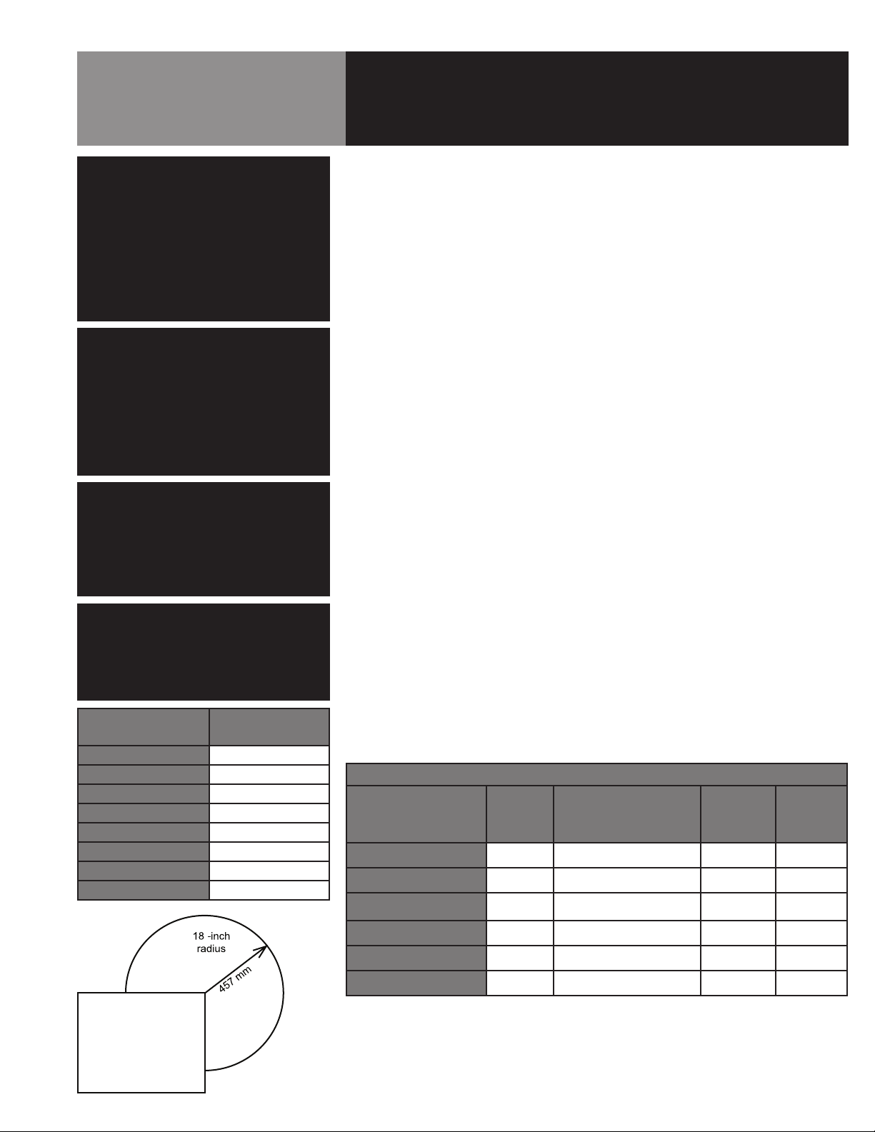
Steam Free Zone: The boilerless steamer can be damaged by steam from external
sources. Do not install the steamer over a steam venting drain. Ensure that steam is
not present in an area bounded by the footprint of the steamer and a circle 18 inches
in radius about the right rear corner of the steamer (see figure at left).
Install and operate the gas appliance in a well ventilated area. Adequate air must be
supplied to replenish the air used for combustion. Installation must conform with local
codes and/or with the National Fuel Gas Code, ANSI Z223.1/NFPA-54 (latest edition) or
the National Gas and Propane Code CSA B149.1 as applicable.
Any item which might obstruct or restrict the flow of air for combustion and ventilation
must be removed. Do not obstruct the flue cover or rear vents after installation.
The steamer must be disconnected from the gas supply system during any pressure
testing of that system which has test pressures in excess of 1/2 PSI (3.45 kPa).
1. Electrical Supply Connection
Provide 115 VAC, 60 HZ, 1 PH, 15 AMP service. Bring wire in through hole in the
lower left back panel. Each cavity requires a separate cord for connections. Local
codes and/or the National Electrical Code should be observed in accordance with
ANSI/NFPA 70. AN ELECTRICAL GROUND IS REQUIRED. The wiring diagram is
located in the service compartment and in this manual. Maximum load is 21/2
AMPs. In Canada, provide electrical service in accordance with the Canadian
Electrical Code, CSA C22.2 Part 1 and/or local codes.
Steamer Type
3-Pan Table Top 1/2
3-Pan on stand 1/2
(2) 3-Pan on stand 1/2
5-Pan table top 1/2
5-Pan on stand 1/2
(2) 5-Pan on stand 1/2
10-Pan on stand 3/4
(2) 10-Pan on stand 3/4
NPT Pipe Size
Required
2. Gas Supply Connection
Connection to the gas supply shall be in accordance with the chart at left.
GAS RATINGS
Steamer Type BTU/hr
3-Pan Natural Gas
3-Pan LP Gas
5-Pan Natural Gas
5-Pan LP Gas
10-Pan Natural Gas
10-Pan LP Gas
54,000 4.30" WC 5" WC 14" WC
54,000 10.5" WC 12" WC 14" WC
62,000 4.25" WC 5" WC 14" WC
62,000 10.5" WC 12" WC 14" WC
106,000 4.30" WC 5" WC 14" WC
106,000 10.5" WC 12" WC 14" WC
Operating Pressure
(measured on top of gas valve)
Minimum
Incoming
Gas Feed
Maximum
Incoming
Gas Feed
After the unit has been connected to the gas supply, all gas joints must be
checked for leaks. Do NOT use flame checking for leaks. A thick soap solution or
other suitable leak detector should be used.
OM-SBC-G 5
Page 8

Installation
WARNING
DO NOT CONNECT THE DRAIN DIRECTLY
TO A BUILDING DRAIN. BLOCKING THE
DRAIN IS HAZARDOUS.
CAUTION
DO NOT USE PLASTIC PIPE. DRAIN MUST BE
RATED FOR BOILING WATER.
IMPORTANT
DO NOT ALLOW WATER TRAPS IN THE LINE.
A TRAP CAN CAUSE PRESSURE BUILD-UP IN
THE CAVITY, WHICH MAY CAUSE THE DOOR
GASKET TO LEAK.
Steamer Type NPT Pipe Size Required
3-Pan
(2) 3-Pan
5-Pan
(2) 5-Pan
10-Pan
(2) 10-Pan
1.5"
2.5"
1.5"
2.5"
2.0”
2.0"
For a Unit on casters:
a. The installation shall be made with a connector that complies with the
standard for connectors for movable gas appliances; ANSI Z21.69.CSA
6.16, and a quickdisconnect device that complies with the standard for
quick-disconnect devices for use with gas fuel, ANSI Z21.41.CSA 6.9.
b. Adequate means must be provided to limit the movement of the appliance
without depending on the connector and the quick disconnect device or its
associated piping to limit the appliance movement.
c. The location where the restraining device may be attached to the appliance
shall be in accordance with specifications for the device.
3. Water Connection(s)
Install a check valve to prevent back flow in the incoming cold water line, as
required by local plumbing codes. Water pressure in the line should be between
30 and 60 PSI. If pressure is above 60 PSI, a pressure regulator will be needed.
These pressures must provide the 1.5 gallons per minute required for proper
steamer function.
A 3/4 inch female NH connector (garden hose type) is used to attach the water
supply to the inlet valve. Minimum inside diameter of the water feed line is 1/2
inch. Use a washer in the hose connection. Do not allow the connection to leak,
no matter how slowly. Do not over-tighten hose connections.
This equipment is to be installed to comply with the basic plumbing code of the
Building Officials and Code Administrators International, Inc. (BOCA) and the Food
Service Sanitation Manual of the Food and Drug Administration (FDA).
NOTE: Local code may also require check valves in the water supply line.
4. Drain Connection
Level the steamer front to back, and pitch it slightly to the rear (maximum 1/4
inch) by adjusting the optional legs or the bullet feet on the optional stand.
There must be a free air gap between the end of the hose and the building drain.
The free air gap should be as close as possible to the unit drain. There must also
be no other elbows or restrictions between the unit drain and the free air gap.
Install the drain line with a constant downward pitch.
Proper Drain Line Connection –– Drain Line must have a constant downward
pitch of at least 1/4” per foot. Observe local code regarding air gap spacing and
drain connections.
6 OM-SBC-G
Page 9

Installation
WARNING
DO NOT STACK STEAMERS WHEN
LEGS ARE USED.
5. Factory-Stacked Units
This section is applicable only if you are installing factory-stacked units.
Installing stacked steamers is similar to installing a single unit. The steamers are
stacked and assembled at the factory and delivered with the water connections
and drain hoses required for a single point connection.
a. Water Connection
The same water supply connection is used for both units. At the water inlet
valve a 3/4 inch female NH connector (garden hose type) is used for the
water supply.
b. Electrical Supply Connection
Separate electrical connections will be required for each steamer to be
stacked. Each steamer unit must have it’s own branch circuit protection.
c. Gas Connection
A single gas connection is required for both steamers. Gas supply must be
adequate under all conditions as listed on page 6.
d. Drain Connection
Steamers must be leveled front to back, and pitched to the front (maximum
1/4 inch) by adjusting the bullet feet on the cabinet or stand base.
For all factory-stacked steamers, a 2-1/2 inch ID hose is attached to the
unit drain. It must be rated for boiling water.
6. Counter-Mounted Units
This section is applicable if the steamer will be mounted to a counter. All four
edges of the bottom of the steamer must be sealed with RTV to the counter if the
4 inch legs are not used. Counter must be made of a noncombustible material
such as metal or tile.
OM-SBC-G 7
Page 10

Initial Start-Up
WARNING
WHEN YOU OPEN THE DOOR, STAY AWAY
FROM STEAM COMING OUT OF THE UNIT.
STEAM CAN CAUSE BURNS.
After the boilerless steamer has been installed, test it to ensure that the unit is
operating correctly.
1. Remove all literature and packing materials from the interior and exterior of the
unit.
2. Make sure the water supply line is open.
3. Make sure that the gas supply line is open and that the manual knob on the
main gas valve is turned to the ON position. This valve is at the rear on the right
side of the unit.
4. Turn on electrical service to the unit. The steamer will not operate without
electrical power. Do not attempt to operate the unit during a power failure.
NOTE: The door MUST be closed for the main burner to work.
5. To turn the unit on, press the ON switch on the control panel.
6. When the steam generating reservoir has filled with water, the main burners
will ignite automatically. Within 20 minutes or less the READY light will come on,
indicating that the water has reached its standby temperature. When the READY
light is displayed, you may take any one of the following steps;
a. Push TIMED and set the timer knob to the desired steaming time.
b. Push MANUAL for continuous steaming.
c. Push STOP to let the unit stay at ready condition.
7. To shut down the unit, press the OFF switch. The steam generating reservoir will
then fill with cold water and drain.
8. If the steamer operates as described, the unit is functioning correctly and ready
for USE.
NOTE: For operation at high altitudes (2000 feet and above), please consult the
Foodservice Engineering Department.
8 OM-SBC-G
Page 11

Operation
A. Controls
Operator controls are on the front right of the unit.
The control panels have the following touch pads and indicator lights:
1. The TIME display shows the remaining cooking time. It displays three
dashes in MANUAL mode.
MANUAL
TIMED
STOP
CANCEL
READY
TIME display
TIMER knob
MANUAL button
and indicator
TIMED button
and indicator
STOP button
and indicator
CANCEL button
and indicator
FAULT display
READY indicator
2. The ON/OFF rocker switch gets the unit ready for use or shuts it off.
3. The READY indicator light indicates the unit has achieved the ready
temperature.
4. Hour meter records cumulative hours of operation.
5. The FAULT display shows the current fault.
The push button operations:
1. In the STOP mode the steam generator stays at a low boil or ready
temperature.
2. When the TIMED button is pushed , the TIMED light will illuminate and
time can be set by turning the TIMER knob (cook time can be increased or
decreased at any time by turning the timer knob). The unit steams until the
timer counts down to zero and the temperature drops to ready. At that time
the STOP light illuminates and a beeper sounds.
3. When the MANUAL button is pushed, the unit steams continuously. The
MANUAL light will stay illuminated.
4. CANCEL button should be pushed to stop beeping.
ON
OFF
HOURS
For service/support call
866-518-3977
www.blodgett.com
ON/OFF
rocker switch
Hour meter
170155 REV. A
OM-SBC-G 9
Page 12

Operation
WARNING
WHEN YOU OPEN THE DOOR, STAY AWAY
FROM THE STEAM COMING OUT OF THE
UNIT. THE STEAM CAN CAUSE BURNS.
High Float
Low Float
Empty
B. Operating Procedure
1. Press the ON/OFF rocker to the ON position, (Fi
display window. The steam generating reservoir will begin filling, displaying
) and (Fi ) as it fills. After initial fill the unit will begin draining
(Fi
displaying (Fi
READY light comes on (about 15-20 minutes).
2. Load food into pans in uniform layers. Pans should be filled to about the
same levels, and should not be mounded.
3. Open the door and slide the pans into the supports. If you will only be
steaming one pan, put it in the middle position. Some foods will cause
foam. When cooking foods that foam, such as shrimp, put an empty solid
2½” deep pan in the bottom slot of the pan racks.
4. Close the door. When the READY indicator is lit take one of the following steps:
If you want to steam the food for a certain length of time push the TIMED
button and set the desired time with the TIMER knob. The timer will
automatically run the steamer for the set time and then STOP. A beeper will
sound. Push CANCEL to stop beeping.
If you want to steam continuously push the MANUAL button. The unit will
continue steaming until stopped.
), refilling displaying (Fi ), and then begin heating until the
) is displayed in the TIME
Push STOP to stop producing steam.
5. To remove pans from cavity open the door. Remove the pans from the
steamer using hot pads or oven mitts to protect your hands from the hot
pans.
6. To shut off the unit press the ON/OFF rocker switch to OFF, (FL
appear in the timer display. The steam generating reservoir will begin
draining, displaying (Fi
twice and finally drain completely and turn off the unit.
NOTE: When filling or draining the steam generating reservoir (
displayed indicating the water level in the reservoir. (
(
NOTE: If a large amount of shrimp is cooked in the unit, foaming will occur
* To avoid this use a catch pan to catch shrimp drippings and proteins to
) low float is satisfied, ( ) high float is satisfied.
because the steam lid actually gets so hot that the shrimp will cook on its
surface and the shrimp proteins in the dripping will foam on the surface of
the steam lid.
prevent foaming when cooking a large amount of shrimp.
) and (Fi ) as it drains, and refill to the high float
) reservoir is empty,
) will
) will be
10 OM-SBC-G
Page 13

Cleaning
WARNING
DISCONNECT THE POWER SUPPLY
BEFORE CLEANING THE OUTSIDE OF
THE STEAMER.
KEEP WATER AND CLEANING SOLUTIONS
OUT OF CONTROLS AND ELECTRICAL
COMPONENTS. NEVER HOSE OR STEAM
CLEAN ANY PART OF THE UNIT.
AVOID CONTACT WITH ANY CLEANERS,
DELIMING AGENT OR DEGREASER AS
RECOMMENDED BY THE SUPPLIER. MANY
ARE HARMFUL. READ THE WARNINGS AND
FOLLOW THE DIRECTIONS!
EVEN WHEN THE UNIT HAS BEEN SHUT
OFF, DON’T PUT HANDS OR TOOLS
INTO THE COOKING CHAMBER UNTIL
THE FAN HAS STOPPED TURNING.
DON’T OPERATE THE UNIT UNLESS THE
REMOVABLE PARTITION HAS BEEN PUT
BACK IN ITS PROPER LOCATION.
DON’T USE ANY CLEANING AGENT
THAT CONTAINS ANY SULFAMIC
AGENT OR ANY CHLORIDE,INCLUDING
HYDROCHLORIC ACID (HCL). TO
CHECK FOR CHLORIDE CONTENT SEE
ANY MATERIAL SAFETY DATA SHEETS
PROVIDED BY THE CLEANING AGENT
MANUFACTURER.
To keep your boilerless steamer in proper working condition, use the following procedure to clean the unit. This regular cleaning will reduce the effort required to clean the
steam generator and cavity.
A. Suggested Supplies
1. Mild detergent
2. Stainless steel exterior cleaner
3. Cloth or sponge
4. Brush with soft bristles
5. Spray bottle
6. Measuring cup
7. Nylon pad
8. Towels
9. Plastic disposable gloves
10. Funnel
B. Procedure
1. Exterior Cleaning
a. Prepare a warm solution of the mild detergent as instructed by the
supplier. Wet a cloth with this solution and wring it out. Use the moist
cloth to clean the outside of the unit. Do not allow freely running liquid
to touch the controls, the control panel, any electrical part, or any
louver on the rear panels.
b. To remove material which may be stuck to the unit, use a fiber brush
or a plastic or rubber scraper with a detergent solution.
c. Stainless steel surfaces may be polished with a recognized stainless
steel cleaner.
2. Interior Cleaning
Daily cleaning must be done in order to enhance the performance and
prolong the life of your boilerless steamer.
IMPORTANT
DO NOT USE ANY METAL MATERIAL
(SUCH AS METAL SPONGES) OR METAL
IMPLEMENTS (SUCH AS A SPOON, SCRAPER
OR WIRE BRUSH) THAT MIGHT SCRATCH
ANY STAINLESS STEEL SURFACE.
SCRATCHES MAKE THE SURFACE HARD
TO CLEAN AND PROVIDE PLACES FOR
BACTERIA TO GROW. DO NOT USE STEEL
WOOL, WHICH MAY LEAVE PARTICLES
EMBEDDED IN THE SURFACE,
WHICH COULD EVENTUALLY CAUSE
CORROSION AND PITTING.
OM-SBC-G 11
Page 14

Cleaning
WARNING
ALLOW THE STEAMER TO COOL
COMPLETELY BEFORE CLEANING. HOT
SURFACES CAN CAUSE SEVERE BURNS.
WARNING
FAILURE TO CLEAN THE STEAMER AS
SPECIFIED COULD NEGATIVELY IMPACT
THE PERFORMANCE OF THE STEAMER.
C. Cleaning Steps
STEP 1 - Press OFF switch to turn steamer OFF and open steamer door.
STEP 2 - CAUTION: allow the steamer to cool completely before cleaning.
STEP 3 - Remove steam lid by grasping the two tabs located on the lid front and
sliding pan forward.
STEP 4 - Remove left pan rack by lifting rack up and pulling away from cavity
wall.
STEP 5 - Remove right fan shroud and rack assembly by lifting rack up and pull-
ing away from cavity wall.
STEP 6 - Clean steam lid, left pan rack and rack/ shroud assembly to remove
food soils. These three parts may be cleaned in a dishwasher.
STEP 7 - Use a mild detergent to wipe down the entire steamer cavity to remove
food and scale particles. Carefully clean float probes if food residue or loose
scale is present. A thin layer of tightly bound scale is normal and will not affect
steamer performance. If scale is excessive, then refer to deliming instructions
below.
STEP 8 - Remove drain strainer and clean thoroughly to remove any build-up of
debris.
STEP 9 - Replace pan racks and steam lid. Steamer is now cleaned and ready to
use.
D. Deliming Instructions
When using a Water Treatment System use vinegar as a deliming agent.
Commercial delimer may be used to remove excessive scale build-up.
STEP 1 - After following all cleaning steps 1 through 7 listed above, turn steamer
on and allow water to enter steamer cavity.
STEP 2 - Pour 1 cup of vinegar or delimer into steamer cavity and shut door.
STEP 3 - Set steamer timer to 30 minutes and allow steam cleaning to occur.
STEP 4 - After 30 minutes cleaning cycle is complete, turn steamer OFF and al-
low to cool completely.
STEP 5 - Open steamer door and wipe down the entire steamer cavity to remove
loosened scale particles. Carefully clean float probes if loose scale is present.
STEP 6 -Replace pan racks and steam lid. Steamer is now cleaned and ready to
use.
12 OM-SBC-G
Page 15

Maintenance
The boilerless steamer is designed for minimum maintenance and no user adjustments should be necessary. Certain parts may need replacement after prolonged
use. If there is a need for service, only Authorized Service Agents should perform the
work.
If steam or condensate is seen leaking from around the door, take the following
steps:
1. Check the door gasket. Replace it if it is cracked or split.
2. Inspect the cooking chamber drain to be sure it is not blocked.
3. Adjust the door latch pin to allow for changes that might occur as the gasket
ages.
a. Loosen the lock nut at the base of the latch pin, then turn the latch pin
1/4 turn clockwise, and tighten the lock nut.
b. After adjustment, run the unit to test for further steam leakage.
c. If there is still leakage, repeat the adjustment
d. Continue adjusting the pin clockwise until the door fits tightly enough to
prevent leakage. The hinge may also be adjusted.
OM-SBC-G 13
Page 16

Troubleshooting
Your boilerless steamer is designed to operate smoothly and efficiently if properly maintained. However, the following is a list of
checks to make in the event of a problem. Wiring diagrams are furnished inside the service panel. If an item on the check list is
marked with (*), it means that the work should be done by an Authorized Service Agent.
SYMPTOM WHO WHAT TO CHECK
Fault Display 1 or 2. User a. Clean floats in unit / Check float probe orientation
b. Be sure water supply is adequate to run steamer(s) during normal operation.
No power. User a. Check wall circuit breaker.
b. Disconnect power, then check fuses inside steamer.*
c. Call service technician.
Unit overfills with water at start
up.
Steamer does not fill with
water.
“Door” Shown in Time Display
Window.
User a. Clean floats in unit / Check float probe orientation.
b. Clean drain strainer.
c. Call service technician.
User a. Is the ON switch depressed?
b. Is the water supply connected?
c. Is the water turned on?
d. Is the water supply hose kinked or obstructed?
e. Check for low water pressure (less than 30 PSI) or low water flow (less than 1.5
gpm).
f. Is the screen at the water connection clogged?
User a. Is the steamer door securely closed?
No steam. User a. Is the ON switch depressed?
b. Is the water supply connected?
c. Is the water turned on?
d. Is steamer door completely closed?
Fault Display 7. User a. The component cooling fan may not be operating. The display may come on for
several minutes during normal operation. If it stays on for more than 30 minutes,
call service technician. Unit may be used for cooking, while waiting for service.
Any unusual operation. User a. Press OFF switch to turn steamer off. Momentarily turn circuit breaker off and then
turn unit back on.
Door pops open. User a. Ensure drain and vent are not plugged. No more than two units should be attached
to a single drain line.
b. Check door pin adjustment per above.
c. Call service technician.
Fault Display 6. User a. Wait 30 minutes for unit to cool down.
b. Call service technician.
14 OM-SBC-G
Page 17

Parts List
Boilerless Steamer
OM-SBC-G 15
Page 18

Parts List
Boilerless Steamer
16 OM-SBC-G
Page 19

36
Parts List
Boilerless Steamer
29
31
30
32
37
35
34
33
OM-SBC-G 17
Page 20

Parts List
Boilerless Steamer
To order parts, contact your Authorized Service Agent. Supply the model designation, serial number, part description, part number,
quantity, and when applicable, voltage and phase.
Key
1
IGNITION MODULE
2
CAPACITOR, 6MF
3
TRANSFORMER 120V PRIMARY/ 24V SECONDARY, 75VA
4
FLUESTACK, SINGLE (3-PAN)
4
FLUESTACK, SINGLE (5-PAN)
4
FLUESTACK, SINGLE (10-PAN)
4
FLUESTACK, DOUBLE (3-PAN)
4
FLUESTACK, DOUBLE (5-PAN)
4
FLUESTACK, DOUBLE (10-PAN)
5
FUSEHOLDER
6
FUSE
7
GROUND TERMINAL
8
TERMINAL BLOCK
9
MAIN GAS VALVE
10
WATER VALVE
11
MUFFIN FAN
12
DRAIN BOX (3-PAN/5-PAN)
12
DRAIN BOX (10-PAN)
13
HI-LIMIT
14
THERMOSTAT (DRAIN BOX)
15
DRAIN VALVE
16A
CONDENSATE CUP
16B
GASKET, CONDENSATE CUP
17
READY THERMOSTAT
18
FLOAT PROBE
19
GAS VALVE
20
DOOR SWITCH
21
POWER SWITCH
22
DOOR ASSEMBLY, COMPLETE (3-PAN)
22
DOOR ASSEMBLY, COMPLETE (5-PAN)
22
DOOR ASSEMBLY, COMPLETE (10-PAN)
23
KNOB
24
CONTROL BOARD
25
MOTOR ASSEMBLY
26
RELAY BOARD
27
IGNITOR (3-PAN/5-PAN)
27
IGNITOR (10-PAN)
28
FLAME SENSE
29
BURNER (3-PAN/5-PAN)
29
BURNER (10-PAN)
Description
Part #
140184
096812
121715
143957
141991
145254
143965
143567
145531
077840
119823
106412
003887
098443
071235
153505
150659
150661
144484
145248
071234
150628
142613
147285
149880
098458
096857
160920
130858
125922
143874
160921
160648
146880
160649
143559
149009
143673
143976
145074
Key
30
TOP PANEL (3-PAN/5-PAN)
30
TOP PANEL (10-PAN)
31
FRONT PANEL OVERLAY (3-PAN)
31
FRONT PANEL OVERLAY (5-PAN/10-PAN)
32
DOOR LATCH PIN
33
DOOR PIN LOCK NUT
34
STEAM LID (3-PAN/5-PAN)
34
STEAM LID (10-PAN)
35
CAVITY FAN
36
LEFT PAN RACK (3-PAN)
36
LEFT PAN RACK (5-PAN)
36
LEFT PAN RACK (10-PAN)
37
DOOR HANDLE
38
DOOR GASKET (3-PAN)
38
DOOR GASKET (5-PAN)
38
DOOR GASKET (10-PAN)
X
MOTOR SHAFT SEAL
X
BLOWER COVER (3-PAN)
X
BLOWER COVER (5-PAN)
X
BLOWER COVER (10-PAN)
X
RIGHT PAN RACK (3-PAN)
X
RIGHT PAN RACK (5-PAN)
X
RIGHT PAN RACK (10-PAN)
X
DRIP TRAY
X
LEFT SIDE PANEL (3-PAN)
X
LEFT SIDE PANEL (5-PAN)
X
LEFT SIDE PANEL (10-PAN)
X
RIGHT SIDE PANEL (3-PAN)
X
RIGHT SIDE PANEL (5-PAN)
X
RIGHT SIDE PANEL (10-PAN)
X
FLOW REDUCER, CONDENSATE
X
FLOW REDUCER, FILL
X
HARNESS, CONTROL TO RELAY BOARD
X
HARNESS, REAR
X
HARNESS, LOW VOLTAGE
X
HARNESS, IGNITION
X
HARNESS, FORWARD
X
HARNESS, STEAMER HIGH VOLTAGE
X
JUMPER, VOLTAGE SELECT 120VAC
X
HARNESS, JUMPER
Description
Part #
150637
149444
170155
170156
078914
003823
149299
149452
096790
149883
149872
145642
070123
124849
125907
143879
096868
149387
149313
149451
141571
140157
145721
094151
149229
149233
149446
149231
149235
149448
147371
144481
160885
160883
160881
153339
153338
160874
123123
123125
18 OM-SBC-G
x- Item not depicted/called out in drawing or photograph
Page 21

Wiring Diagram
OM-SBC-G 19
Page 22

Service Log
Model No: Purchased From:
Serial No: Location:
Date Purchased: Date Installed:
Purchase Order No: For Service Call:
Date Maintenance Performed Performed By
20 OM-SBC-G
Page 23

Page 24

BLODGETT OVEN COMPANY
www.blodgett.com
44 Lakeside Avenue, Burlington, Vermont 05401 USA
Telephone: 866-518-3977
PART NUMBER 170209 REV A (04/11)
 Loading...