

Page 1

HV-100EM
CONVECTION OVEN WITH MOISTURE
INSTALLATION - OPERATION - MAINTENANCE
NSN: 7310-01-600-5659
APL: 43A090038
BLODGETT OVEN COMPANY
www.blodgett.com
44 Lakeside Avenue, Burlington, Vermont 05401 USA Telephone: (802) 658-6600 Fax: (802)864-0183
PN 51702 Rev L (4/14)
© 2014 - G.S. Blodgett Corporation
Page 2

Your Service Agency’s Address:
Model
Serial number
Oven installed by
Installation checked by
Page 3

IMPORTANT
TABLE OF CONTENTS
WARNING: Improper installation, adjustment, alternation,
service or maintenance can
cause property damage, injury or death. Read the instllation, operation and maintenance instructions thoroughly
before installing or servicing
this equipment.
FOR YOUR SAFETY
Do not store or use gasoline or
other ammable vapors or liquids in the vicinity of this or any
other appliance.
The information contained in this
manual is important for the proper installation, use, and maintenance of this oven. Adherence
to these procedures and instructions will result in satisfactory
baking results and long, trouble free service. Please read
this manual carefully and retain
it for future reference.
ERRORS: Descriptive, typographic or pictorial errors are
subject to correction. Specications are subject to change
without notice.
INSTALLATION
Oven Description and Specications ....................................... 2
Utility Connections - Standards and Codes ................................. 3
Oven Location and Shipping .............................................. 4
Ventilation ............................................................... 5
Oven Assembly
Possible Leg Bolting Patterns ......................................... 6
Leg Attachment ...................................................... 7
Oven Stacking ....................................................... 8
Utility Connections ................................................... 8
Supply Water and Plumbing .............................................. 10
Electrical Supply ....................................................... 11
OPERATION
MenuSelect Control
Control Description .................................................. 12
Oven Startup ....................................................... 13
Manual Cooking ..................................................... 13
Programmed Cooking ............................................... 13
Probe Cooking ...................................................... 13
During Any Cook Cycle .............................................. 14
At the End of Any Cook Cycle ........................................ 14
Oven Shutdown ..................................................... 14
Product Programming ............................................... 15
Using the USB Port .................................................. 16
Manager Programming .............................................. 17
MAINTENANCE
Spray Bottle Operating Procedure ........................................ 18
Cleaning and Preventive Maintenance .................................... 19
Replacement Parts ..................................................... 21
Second Level Programming .............................................. 29
Troubleshooting ......................................................... 30
Sequence of Operation .................................................. 32
Component Resistance Readings ........................................ 34
Probe Ohms Chart ...................................................... 34
Wiring Diagrams ........................................................ 35
Page 4

Installation
Oven Description and Specications
Blodgett ovens are quality produced using high grade
stainless steel with rst class workmanship.
The multiple speed fan, which is guarded against acci-
dental nger contact, is driven by a quiet and powerful
motor. The condenser draws out excess moisture from
the appliance. Condensation and waste water, which result during hydro cooking and cleaning, are continuously
drained.
The use of high quality insulation impedes excessive heat
radiation and saves energy.
The HV-100EM has legs which adapt easily to slightly uneven surfaces.
The practical oven doors, with viewing windows, have a
wide swing radius and handle which can be operated easily, even with wet or greasy hands.
ELECTRICAL RATINGS
VOLTAGE
440 60 15 3 20 18 18 3/4 HP 208-240VAC, 50/60 Hz
HZ
KW
PHASE
MAX LOAD (AMPS)
L1 L2 L2
Ease of operation is guaranteed through the simple arrangement of the controls. Graphic symbols make the appliance easy for even inexperienced kitchen staff to operate. The Cool Down mode, allows the oven cavity to cool
down rapidly with the door opened.
Cleaning is kept to a minimum. The interior is sprayed
with a self-acting cleaning solution which interacts with
humidity to easily remove crusts and stains. The oven is
designed for easy care and is welded water tight so that
the internal cooking cavity may be rinsed with a hose after
the cleaning process.
MOTOR
PLUMBING SPECIFICATIONS
WATER
Water pressure 30 PSI (207 kPa) minimum
50 PSI (345 kPa) maximum
Water connection 3/4” garden hose - Cold water only
Water pressure regulator setting Preset to 20 PSI (138 kPa)
Flow rate of 4 GPH
Minimum requirements TDS - less than 100 parts per million
Total Hardness - 80-120 parts per million
Chlorides - less than 30 parts per million
Chlorine - 0 parts per million
pH Factor - 7.0-8.0
DRAINAGE
Drain type Atmospheric Vented Drain
Drain connection 1” NPT Male
2
Page 5

Installation
Utility Connections - Standards and Codes
THE INSTALLATION INSTRUCTIONS CONTAINED
HEREIN ARE FOR THE USE OF QUALIFIED INSTALLATION AND SERVICE PERSONNEL ONLY. INSTALLATION OR SERVICE BY OTHER THAN QUALIFIED
PERSONNEL MAY RESULT IN DAMAGE TO THE OVEN
AND/OR INJURY TO THE OPERATOR.
Qualied installation personnel are individuals, a rm,
a corporation, or a company which either in person or
through a representative are engaged in, and responsible
for:
• the installation or replacement of gas piping and the
connection, installation, repair or servicing of equipment.
• the installation of electrical wiring from the electric
meter, main control box or service outlet to the electric appliance.
Qualied installation personnel must be experienced in
such work, familiar with all precautions required, and have
complied with all requirements of state or local authorities
having jurisdiction.
U.S. and Canadian installations
The installation must conform with local codes, or in the
absence of local codes, with the National Fuel Gas Code,
ANSI Z223.1/NFPA 54, or the Natural Gas and Propane
Installation Code, CSA B149.1, as applicable.
Installation must conform with local codes, or in the absence of local codes, with the National Electrical Code,
ANSI/NFPA 70-Latest Edition and/or Canadian National
Electric Code C22.1 as applicable.
Appliance is to be installed with backow prevention in
accordance with applicable federal, province and local
codes.
Australia and general export installations
Instllation must conform with Local and National installation standards. Local installation codes and/or requirements may vary. If you have any questions regarding the
proper installation and/or operation of your Blodgett oven,
please contact your local distributor. If you do not have a
local distributor, please call the Blodgett Oven Company
at 0011-802-658-6600.
3
Page 6

Installation
Oven Location and Shipping
OWNER’S RESPONSIBILITIES
Installation responsibilities prior to service startup inspection
You are entitled to a free start-up inspection service by
our factory ASAP. Before a factory representative arrives
to perform a startup procedure, the owner must already
have satised the following requirements.
1. Oven(s) are uncrated, stacked (if applies) and put in
place.
NOTE: Please refer to Leg Attachment and Stacking.
Maximum shelf loading - 60 lbs (27.3 Kg)
OVEN LOCATION
The well planned and proper placement of your oven will
result in long term operator convenience and satisfactory
performance.
Certain minimum clearances must be maintained between the oven and any combustible or non-combustible
construction.
• Oven body sides - 0” (0cm)
• Oven body back - 6” (152.4cm)
SHIPPING
NOTE: The following parts are shipped with the oven.
PART # DESCRIPTION QTY.
R10955 Cleaning spray bottle 1
33136 Power cord 2
52723 Drain elbow connection 2
52724 5’ drain hose 1
R2207 Hose clamp 4
R10889 10’ water hose 1
52728 3’ water hose 1
52596 Water manifold 1
52713 Utility box 1
52734 Utility line retainer bracket 1
52715 Vent extension bracket 1
52349 Cavity vent extension 1
52648 4” vent extension hose 1
33196 Seismic legs, set 1
315 1/2-13 x 3/4” stacking bolts 4
34907 Kit, set of ship deck legs 1
In addition, the following clearances are recommended
for servicing.
• Oven body sides - 12” (30cm)
• Oven body back - 12” (30cm)
4
Page 7

VENTILATION
The necessity for a properly designed and installed ventilation system cannot be over emphasized. The ventilation system will allow the unit to function properly while
removing unwanted vapors and products of combustion
from the operating area.
The appliance must be vented with a properly designed
mechanically driven exhaust hood. The hood should be
sized to completely cover the equipment plus an overhang of at least 6” (15 cm) on all sides not adjacent to a
wall. The capacity of the hood should be sized appropriately and provisions made for adequate makeup air.
WARNING!!
Failure to properly vent the oven can be hazardous to the health of the operator; and will
result in operational problems, unsatisfactory
baking, and possible damage to the equipment. Damage sustained as a direct result of
improper ventilation will not be covered by the
Manufacturer’s warranty.
Installation
Ventilation
When installed in the Commonwealth of Massachusetts,
this appliance must be interlocked with the hood exhaust
system so that the appliance may be operated only when
the hood exhaust system is running.
U.S. and Canadian Installations
Refer to your local ventilation codes. In the absence of
local codes, refer to the National ventilation code titled,
“Standard for the Installation of Equipment for the Removal of Smoke and Grease Laden Vapors from Commercial
Cooking Equipment”, NFPA-96- Latest Edition.
General Export Installations
Installation must conform with Local and National installation standards. Local installation codes and/or requirements may vary. If you have any questions regarding the
proper installation and/or operation of your unit, please
contact your local distributor. If you do not have a local
distributor, please call Blodgett at 0011-802-658-6600.
5
Page 8

Installation
Oven Assembly
POSSIBLE LEG BOLTING PATTERNS
There are two leg mounting options. See Figure 1.
36.19 (2 PLACES)
27.94 (2 PLACES)
.875 (8 PLACES)
35.00 (2 PLACES)
26.75 (2 PLACES)
.313 (8 PLACES)
35.00 (2 PLACES)
2.50
(4 PLACES)
36.19 (2 PLACES)
3.50 (4 PLACES)
.56 HOLE (4 PLACES)
See page 4 for
part numbers
Figure 1
6
Page 9

LEG ATTACHMENT
1. Align the threaded stud on the right front leg to the
bolt hole located in the bottom corner of the oven.
Turn the leg clockwise and tighten to the nearest full
turn.
2. Align the leg plate holes with the bolt holes.
Figure 2
3. Install the utility box before securing the right front
leg. Align the holes in the utility box bracket to the
holes in the leg plate. See Figure 3.
Installation
Oven Assembly
Figure 4
6. Tip the oven up on the newly installed front legs.
7. Repeat the above steps for the right rear leg.
Install the retainer bracket before securing the right
rear leg. Align the holes in the retainer bracket to the
holes in the right leg plate. See Figure 5.
8. Secure the leg and retainer bracket with the two 3/4”
bolts provided.
4. Secure the leg and utility box with the two 3/4” bolts
provided.
Utility Box
Figure 3
5. Repeat steps 1, 2 and 4 with the left front leg.
Retainer
Bracket
Figure 5
9. Install the left rear leg.
10. Tip the oven onto the feet and place in position. Level
the oven by screwing the adjustable feet in or out as
necessary.
7
Page 10
Installation
Oven Assembly
OVEN STACKING
1. Place the upper oven on top of the lower oven.
2. Bolt the two ovens together from behind using the
stacking brackets.
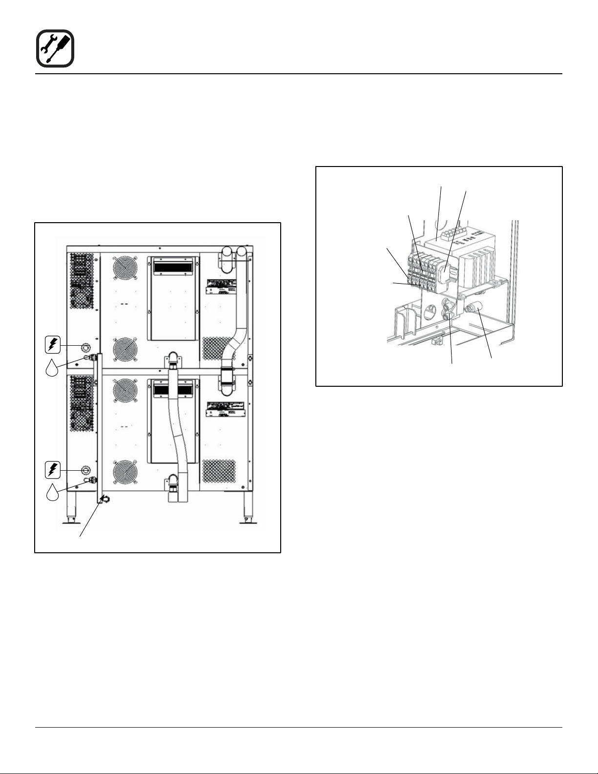
UTILITY CONNECTIONS
NOTE: Refer to Figure 6 for location of utility connection
on the back of the ovens.
Cavity Vents
Electrical
1. Remove the two screws from above and below the
control panel. Slide the panel out to access the terminal blocks. Refer to page 7.
Transformer
Shorting
Jumper
Ground Lug
Terminal
Terminal
Block
1/4 Swivel
Elbow
End Stop
1/4 Straight
Fitting
Water Manifold
Drains
Figure 6
Figure 7
2. Connect the power cord to the top unit. Run the cord
down the back of the oven, using the provided strain
relief.
3. Then route the cord under the oven, supporting it on
the retainer bracket on the rear right leg. Connect to
the top right receptacle on the utility box at the front
of the oven. See Figure 8.
4. Connect the power cord to the bottom unit.
5. Run the cord down the back of the oven, using the
provided strain relief.
6. Then route the cord under the oven, supporting it on
the retainer bracket on the rear right leg. Connect to
the bottom right receptacle on the utility box at the
front of the oven. See Figure 8.
8
Page 11

Top Oven
Electric Cord
Installation
Oven Assembly
Cavity Vent Extension
1. Attach the cavity vent extension using the silicon tubing and two clamps provided.
2. Remove the existing screw and use it to secure the
top section in the bracket. The tabs on the bracket will
deect for a secure t.
Bottom Oven
Electric Cord
Utility
Box
Retainer
Bracket
Figure 8
7. Reattach the right side panels once the electrical connections are complete.
Water and Drain
1. Attach the water manifold to the back of the ovens.
2. Attach the short water hose from the water manifold
to the utility box underneath the oven.
Utility
Box
Utility Supply Connection
1. Connect incoming power from the ship to the electrical connection on the utility box underneath the oven.
See Figure 10.
2. Connect the cold water supply from the ship to the
incoming water connection on the utility box underneath the oven. A 10’ water hose is supplied for your
convenience. See Figure 10.
Incoming
Electrical
Supply
Incoming
Water
Supply
Short
Hose
Water Manifold
Figure 9
3. Attach the supplied elbow assembly to the oven drain
outlet on both units.
4. Attach the supplied drain hose to the top unit.
5. Cut for proper length into the funnel drain. Use the
remaining piece of hose for the bottom oven if necessary. See Figure 6 for location of drain connection on
back of ovens.
Figure 10
9
Page 12

Installation
Supply Water and Plumbing
WATER CONNECTION
NOTE: Must use COLD WATER ONLY.
A shut off valve is to be provided adjacent to the oven.
WARNING!!
Operating the appliance without a water
regulator installed will invalidate your warranty.
This product must be installed by a licensed Plumber or
Gas Fitter when installed within the Commonwealth of
Massachusetts.
DRAIN CONNECTION
The drain should be run to an open oor drain avoiding
exible hose that could sag and allow trapped water to
accumulate.
Specic water/drain connection for City of Los Angeles
1. Each drain line from the appliance shall be routed
without dips or sags to terminate above the ood level
rim of an approved indirect waste receptor.
2. The appliance shall be installed in accordance with
the manufacturer’s printed instructions and the LAPC
and LAMC, 1999 editions.
3. A backow protection device may be required by local codes. If so, install on the potable water system
directly ahead of the appliance. The backow protection device shall be any of the following: an approved
pressure type vacuum breaker installed at least 12”
above the highest point of use, a double check valve
backow preventer or a reduced pressure principal
backow preventer.
10
Page 13

NOTE: Electrical connections must be performed by a
qualied installer only.
Before making any electrical connections to these appliances, check that the power supply is adequate for the
voltage, amperage, and phase requirements stated on
the rating name plate mounted on the appliance.
The circuit breaker that is used to provide power to this
appliance must have a minimum of .076” (3mm) contact
spacing. The circuit breaker must meet all Local and National installation standards.
All appliances must be installed in accordance with Local
or National Electrical codes.
A wiring schematic is located in the slide out panel.
NOTE: Disconnect the power supply to the appliance be-
fore servicing.
Installation
Electrical Supply
WARNING!!
Improper installation may invalidate your warranty.
A strain relief for the power supply cord is provided.
WARNING!!
If the supply cord is damaged, it must be
replaced by a special cord or assembly available from the manufacturer or its service
agent.
Figure 11
11
Page 14

Operation
MenuSelect Control
1
4
CONTROL DESCRIPTION
1. START/STOP KEY - press to start, cancel or pause
the bake
2
3
5
9
2. COOL DOWN KEY - initiates oven cool down cycle
3. BAKE MORE KEY - press at the end of a bake cycle
to add additional bake time in one minute increments
4. DISPLAY - displays time or temperature and other
information related to oven function and/ or programming
5. NAVIGATION PAD - used to enter set points, time,
and programmable settings. Also used to select the
programmed product
6. TEMP KEY - used to set or change the bake temperature
11
14
15
17
18
21
22
23
6
8
7
10
12
13
16
19
20
24
7. TIME KEY - used to set or change the bake time
8. COMBI KEY - press to enter combi mode
9. STEAM KEY - press to enter steam mode
10. HOT AIR KEY - press to enter hot air mode
11. RETHERM KEY - press to enter retherm mode, this
mode uses steam to reheat frozen or precooked product. Retherm has a temperature limit of 250-300°F
12. STEAM ON DEMAND KEY - used to initiate steam
injection cycle
13. PROBE KEY - press to use core probe cooking
14. FAN KEY - press to select the fan speed
15. LIGHT KEY - press to turn the lights on and off
16. VENT KEY - press to manually open and close the
oven vent
17. PROGRAM KEY - press to enter product programming and save programmed settings
18. ESCAPE KEY - press to back up one step during programming
Figure 12
19. MAINTENANCE KEY - press to enter manager programming and save programmed settings
20. ALPHA/NUMERIC KEYPAD - used to program recipes
21. POWER KEY - used to place control in and out of
standby mode
22. CORE PROBE CONNECTION - plug core temperature probe in here when using probe cooking
12
Page 15

Operation
MenuSelect Control
23. CIRCUIT BREAKER - Used to turn power to the unit
on or off
24. USB PORT - Used to download programming information from a USB drive
OVEN STARTUP
1. Be sure the circuit breaker is pushed in. The display
ashes OFF PRESS POWER KEY TO START.
NOTE: If the real time clock and auto wake up func-
tions are enabled the display reads PRESS
POWER KEY TO START AUTO START.
2. Press the POWER KEY (21). The display reads
PREHEAT and the oven heats to the last manual set
temperature in the hot air mode. The display ashes
READY / IDLE and the alarm beeps 5 times when the
oven is at temperature and ready to bake.
MANUAL COOKING
1. Press the arrows on the NAVIGATION PAD (5) until
the display reads MANUAL.
2. Press the TIME KEY (7). Use the either the arrows or
the alpha/numeric keypad to enter the desired bake
time. Press OK on the NAVIGATION PAD (5) to set
the bake time.
NOTE: Time is set in one minute increments using
the arrows. To set time in less than one minute increments use the alpha/numeric keypad.
3. Press the TEMP KEY (6). Use the arrows or the alpha/numeric keypad to enter the desired bake temperature. Press OK to set the bake temperature. The
oven preheats to the new temperature.
NOTE: Temperature is set in 5 degree increments us-
ing the dial. To set time in less than 5 degree
increments use the alpha/numeric keypad.
4. Press the desired mode key, combi, steam, hot air or
retherm.
If Combi or Retherm are selected, use the arrows or
the alpha/numeric keypad to enter the desired percentage of steam.
NOTE: Retherm has a temperature limit of 250-300F.
When the display ashes READY / IDLE, open the
doors. Load the product.
5. Press the START/STOP KEY (1) to begin the bake
cycle. The timer counts down and the display alternates between the cooking mode and the name of
the product.
PROGRAMMED COOKING
1. Press the down arrow key until the name of the product is highlighted, or use the alpha/ numeric keypad
to enter a recipe number. Press OK to select. The
oven preheats to the programmed temperature in the
correct cooking mode. The display ashes READY /
IDLE and the alarm beeps 5 times when the oven is
at temperature and ready to bake.
2. Open the doors. Load the product.
3. Press the START/STOP KEY (1) to begin the bake
cycle. The timer counts down and the display alternates between the cooking mode and the name of
the product.
PROBE COOKING
1. Press the PROBE key (13) to select the probe mode.
The display reads CORE PROBE COOK & HOLD.
Use the arrowsl to select either YES or NO. Press OK
to select.
If YES is selected, Cook & Hold has been enabled. In
the Cook & Hold mode, the oven cavity lowers to the
product pull temperature as the product cooks.
If NO is selected, Cook & Hold has not been enabled
the cavity maintains the cook temperature.
2. Use the arrows to enter the desired product pull temperature in the display. Press OK to save the pull temperature.
3. Press the TEMP KEY (6). Use the arrows or the alpha/numeric keypad to enter the desired bake temperature. Press OK to set the bake temperature. The
oven preheats to the new temperature.
NOTE: Temperature is set in 5 degree increments us-
ing the dial. To set time in less than 5 degree
increments use the alpha/numeric keypad.
13
Page 16

Operation
MenuSelect Control
4. Press the desired mode key, combi, steam, hot air or
retherm.
If Combi or Retherm are selected, use the arrows or
the alpha/numeric keypad to enter the desired percentage of steam.
NOTE: 0 has a temperature limit of 250-300 F.
5. Insert the core probe into the product. Load product
into the oven and close the door. Be sure that the
terminal end of the core probe is outside of the oven
and clear of the door.
6. Connect the core probe to the PROBE CONNECTION (22) at the bottom of the control.
NOTE: Do not connect the probe before the cook
mode has been selected.
7. The display gives the actual core probe temperature
as well as the oven set temperature.
8. When the product reaches the pull temperature the
buzzer sounds.
9. Press the START/STOP KEY (1) to silence the buzzer.
If using Cook & Hold - The cavity temperature continues to drop to the product pull temperature and the
display counts up, telling the operator how long the
product has been held. Disconnect the core probe
and remove the product when ready.
If not using Cook & Hold - The cavity remains at
the cook temperature. The display does not count up.
Disconnect the core probe and remove the product
when the buzzer sounds.
less than one minute increments use the alpha/numeric keypad.
3. The Steam on Demand LED ashes until the steam
time has expired.
Venting Moisture from the Oven Cavity
1. Press the VENT KEY (16). This manually opens the
vent until the key is pressed again to close it.
Pause a Bake Cycle
1. To pause a cook cycle, press the START/ STOP
KEY (1). The LED on the start/stop key ashes. The
bake cycle will pause until the key is pressed again.
Cancel a Cook Cycle
1. To cancel the cook cycle, press and hold the START/
STOP KEY (1).
AT THE END OF ANY COOK CYCLE
1. An alarm sounds, the display reads DONE.
2. If more bake time is desired, press the BAKE MORE
KEY (3). This will add an additional one minute of
time for each press of the key.
3. When you are satised with the bake, press the
START/STOP KEY (1) to silence the alarm. Open the
door to remove the product.
OVEN SHUTDOWN
1. Press the COOL DOWN KEY (2). The display reads
AUTO COOL DOWN ACTUAL TEMP. To speed up
the cool down process, open the doors and press the
VENT KEY (16) to open the vent.
DURING ANY COOK CYCLE
Steam On Demand
While in the Hot Air, Combi or retherm modes, the unit can
be set to steam for a timed period of up to 20 minutes.
At the end of the timed cycle the unit reverts back to the
original setting. Steam On Demand can be used at any
time during the cook cycle.
1. Press the STEAM ON DEMAND KEY (12).
2. Use the arrows or the alpha/numeric keypad to enter
the desired steam on demand time. Press OK to initiate Steam on Demand cycle.
NOTE: Steam on Demand time is set in one minute
increments using the arrows. To set time in
2. When the oven has cooled down, the display reads
OFF PRESS POWER KEY TO START.
NOTE: The lights shut off and the vent closes auto-
matically at the end of the cool down cycle.
14
Page 17

Operation
MenuSelect Control
PRODUCT PROGRAMMING
Entering the Program Mode
1. Press the PROGRAM KEY (17). If the control is password protected, the display reads ENTER CODE. Use the
alpha/numeric keypad to enter the manager passcode.
Press the OK to enter the program mode.
Naming a Product Recipe
NOTE: Use the following procedure to name a new prod-
uct or edit the name of an existing product.
1. For a new recipe, press the down arrow key to the
rst open product. Press OK to select.
To edit an existing name, press the down arrow key
to display the name to be changed. Press OK to select.
2. Use the arrows to scroll down to Edit Name.
Press OK to enter the edit name menu.
3. Use the arrows or the alpha/numeric keypad to select
the rst character. Press OK to advance to the next
character. Repeat for all remaining characters.
NOTE: Product names may be up to 10 characters
long and can contain spaces. Use the #1 key
to insert spaces in a recipe name.
NOTE: To select letters using the keypad, press the
appropriate key once if you need the rst letter on the key, twice for the second and three
times for the third. For example to enter the
letter L press the #5 key three times.
4. Press the PROG KEY (17). With SAVE highlighted,
press OK to save the product name.
4. Use the arrows to select the desired cooking mode.
Choose from combi, steam, hot air or retherm. Press
OK to set the cook mode.
If Combi or Retherm are selected, use the arrows or
the alpha/numeric keypad to enter the desired percentage of steam.
5. Use the arrows or the alpha/numeric keypad to enter
the desired cook temperature. Press OK to set the
bake temperature.
NOTE: Temperature is set in 5 degree increments
using the arrows. To set time in less than 5
degree increments use the alpha/numeric
keypad.
NOTE: Retherm has a temperature limit of 250-300F.
6. Use the arrows to select the desired fan speed.
Choose from gentle, low, high or turbo. Press OK to
set the fan speed.
Programming a Product Recipe
NOTE: The control can hold 99 recipes. Each recipe may
have up to 6 cooking stages.
1. Use the arrows to highlight the name of the product
to be programmed. Press OK to select the product.
2. The display reads PRODUCT NAME: STAGE 1.
Press OK to select the stage.
3. Use the arrows or the alpha/numeric keypad to enter
the desired bake time. Press OK to set the bake time.
NOTE: Time is set in one minute increments using
the arrows. To set time in less than one minute increments use the alpha/numeric keypad.
15
Page 18

Operation
MenuSelect Control
7. Use the arrows to select the fan rotation cycle.
Choose between manual or auto.
NOTE: This is the length of time the fan will rotate in
one direction before reversing.
If manual is selected, use the arrows or the alpha/
numeric keypad to enter the desired fan cycle. Press
OK to set the fan cycle.
If auto is selected, the program will use the default
fan cycle setting. The default is set through the Manager Programming. See page 17.
8. Use the arrows to set the vent position.
Choose between OPEN or CLOSE. Press OK to set
the vent position.
9. Use the arrows to scroll down to PRODUCT NAME:
STAGE 2. Press OK to select stage 2.
10. Repeat steps 2-9 for all remaining stages.
11. When al stages have been programmed, press the
PROGRAM KEY (17). To save the programming, use
the arrows to scroll to YES. Press OK. The control
exits the program mode.
USING THE USB PORT
1. With the power on, remove the cover of the USB port
(24) and insert the USB drive.
2. Press the MAINTENANCE KEY (19).
3. Turn the dial to highlight MANAGER PROGRAM.
Press the center of the dial to select.
4. Turn the dial to highlight either COPY RECIPE FROM
USB or COPY RECIPE TO USB, then press the center of the dial to select.
5. When the transfer is complete, press any key to return to the menu.
6. Turn the dial to highlight EXIT. Press the center of
the dial to select. The display returns to the previous
menu.
7. Turn the dial to highlight EXIT. Press the center of the
dial to select.
16
Page 19

Operation
MenuSelect Control
MANAGER PROGRAMMING
Entering the Manager Program Mode
1. Press the MAINTENANCE KEY (19). If the control
is password protected, the display reads ENTER
CODE. Use the alpha/numeric keypad to enter the
manager passcode. Press OK to enter the program
mode.
2. Use the arrows to highlight OVEN SETUP.
Press OK to select the product.
Programming Auto Start
NOTE: The Auto Start function enables the oven to turn
on at a programmed time of day and preheat to a
programmed temperature.
1. Use the arrows to highlight AUTO START. Press OK
to select.
2. Use the arrows to select either ON or OFF. Press OK
to select.
If ON is selected, the display reads AUTO START 24
HOUR TIME 00:00. Use the arrows to enter the time
you would like the oven to begin preheating. Press
OK to select.
The display reads AUTO START TEMP XXX. Use
the arrows to enter the desired preheat temperature.
Press OK to select.
Programming Oven Setup
These menus allow the manager to set up basic oven
functions
1. Use the arrows to highlight OVEN SETUP. Press
OK to select.
2. Use the arrows to highlight MANAGER PROGRAM.
Press OK to select.
Recipe Password - Select YES or NO to enable
password protection on recipe programming. If YES
is selected the passcode 3124 must be entered to
change recipe programming.
Temp Unit - Select either degrees F or C.
Cool Down Temp - Select the set temperature for
the oven to achieve in Cool Down mode
Temp Disp Rate - Set the rate, in seconds, at which
the display switches between actual and setpoint
temperature
Input Rsp Time - Set the length of time allowed to
input each variable when programming recipes before control automatically exits out
Setback Time - When not used for a period of time,
the oven temperature will automatically reduce to
conserve energy. This variable sets the length of time
the oven remains at the idle temperature before being lowered.
Ready Beep - Select either ON or OFF. This is the audible alarm that sounds when the oven has reached
the set temperature.
Cook Cool Fan - Select either YES or NO. This function allows the control to display OPEN OVEN DOOR
when you are attempting to lower the set temperature
of the oven.
Restore Manual - Select either YES or NO. This
variable enables the oven to remember the last settings used for manual cooking.
4. After editing a function, press OK to save.
5. When all desired functions have been edited, use the
arrows to highlight EXIT. Press OK to exit the manager programming mode.
3. Use the arrows to highlight the oven function you with
to change. Press OK to select. Choose from the following functions:
17
Page 20

Maintenance
Spray Bottle Operating Procedure
NOTE: Only use a commercial oven cleaner/degreaser
with the spray bottle. DO NOT use chemicals that
are not intended as oven cleaners. See chemical
manufacturer’s information for intended use.
1. Unscrew the sprayer head and ll the container to
the MAX mark. Screw the head assembly on rmly to
ensure an airtight seal. The liquid must be clean and
free from foreign matter. Do not overll - space must
be left for compressing air.
2. To build up pressure, pump approximately 20 full
strokes when the container is lled with liquid. The
higher the pressure, the ner the spray. If the container is only partially lled, then more pumping is re-
quired to compress the additional air space.
3. To spray, depress the trigger with your thumb.
4. Adjust spray nozzle for a wide spray pattern.
5. After a period of spraying, the pressure will drop. Restore the pressure by operating the air pump.
6. Release pressure after use by inverting the spray
head and depressing the trigger or by slowly unscrewing the spray head assembly which will allow
air to escape from around the lling aperture.
7. After use, rinse the spray bottle with clean water and
check that the hole in the nozzle is perfectly clean and
clear. Warm water (not hot) used with a household
detergent is a useful cleaning agent for this purpose.
NOTE: Further information can be found in the instruction
leaet supplied with your spray bottle.
WARNING!!
Protective clothing and eyewear should be
worn while using cleaning agents.
Pressure Pump
Spray Head
Pump
Pressure
Vessel
Clean the pump 2 or 3 times per week with warm water
Figure 13
Complete Spray Bottle - P/N R0006
Spray Head Repair Kit - P/N R6332
Spray Trigger
18
Page 21

CLEANING THE INTERIOR
Daily Cleaning
Daily cleaning of the appliance is essential for sanitation,
and to ensure against operational difculties. The stainless steel cavity may corrode with improper cleaning of
the oven. Use an oven cleaning detergent in conjunction
with the supplied spray bottle.
For difcult cleaning, allow the spray-on oven cleaner to
work longer before rinsing.
1. Cool the appliance down to 140°F (60°C) or, if the
oven has been idle, turn to the Steam mode for 3 to 4
minutes in order to warm the cavity surfaces.
Maintenance
Cleaning and Preventive Maintenance
On stainless interiors, deposits of baked on splatter, oil,
grease or light discoloration may be removed with a good
non toxic industrial stainless steel cleaner. Apply cleaners
when the oven is cold and always rub with the grain of
the metal. The racks, rack supports and the blower wheel
may be cleaned in the oven or by removing them from the
oven and soaking them.
NOTE: DO NOT use corrosive cleaners not intended for
oven cleaning on your oven.
Recommended cleaners:
• ECOLAB Greasecutter Plus
2. Fill the spray bottle and pump air into the container
with the pressure pump.
3. Spray the interior of the oven with a cleaning solution.
Be certain to spray cleaner through the fan guard to
cover all surfaces.
NOTE: Never spray water into the appliance when
the temperature is above 212°F (100°C).
4. Let the cleaner work the time recommended by the
cleaning solution manufacturer. For difcult, baked on
grease, etc. allow to work over night.
5. Set the timer for 15 to 20 minutes.
6. Run the oven at 225°F (107°C) in the Steam mode.
This will soften all burned on residue.
7. Rinse the appliance interior with water (a hose is
supplied, but take care that only the interior cavity is
sprayed with water). Wipe the interior dry after rinsing.
8. The doors should be kept slightly open after cleaning.
This will allow the oven to vent and increase the life
of the door gasket.
• CELLO EZ Clean
• Diversey-Lever Advance Oven Cleaner
WARNING!!
Be sure to read and follow the MSDS or
safety instructions on the bottle for your oven
cleaner.
19
Page 22

Maintenance
Cleaning and Preventive Maintenance
Oven Weekly Cleaning
In addition to the daily cleaning, it is necessasry to clean
behind the fan guard of this oven on a weekly basis. This
is necessary for proper functioning of the oven. Scale will
build up on the fan and heat source leading to a less ef-
cient oven.
1. Turn off the oven. Make sure that the oven is cooled
down to under 140°F (60°C).
2. Remove the rack guides.
3. Rotate the two screws on the left side of the fan guard.
Figure 14
4. Remove the fan guard.
5. Thoroughly spray cleaner onto the fan and heat
source. Close the doors to allow the cleaner to work.
6. After ten minutes, rinse the cleaner off. Return the fan
guard to the closed position. Rotate the two screws to
secure the fan guard.
Remove and clean the blower wheel every 6 months.
CLEANING THE EXTERIOR
The exterior of the appliance may be cleaned and kept in
good condition with a light oil. Saturate a cloth and wipe
the appliance when it is cold; wipe dry with a clean cloth.
WARNING!!
DO NOT spray the outside of the appliance
with water or clean with a water jet. Cleaning
with a water jet can impregnate chlorides into
the stainless steel, causing the onset of corrosion.
PREVENTIVE MAINTENANCE
The best preventive maintenance measures are the proper initial installation of the equipment and a program for
cleaning the appliance routinely. The oven requires no lubrication. Contact the factory, the factory representative
or a local Blodgett service company to perform maintenance and repairs should they be required.
Figure 15
20
Page 23

MENUSELECT CONTROL
6
Maintenance
Replacement Parts
2
1
5
10
4
5
12
13
11
3
9
Ref. Part
No. No. Description
1 55178 CONTROL PANEL AND DECAL
2 39122 BOARD, 3 BUTTON PCB
3 53487 CONTROL, NAVIGATIONAL PAD (NAVY)
4 39781 MEAT PROBE JACK
5 M3367 NUT, 6-32 KEPS (QTY 4)
6 5805 SCREW, M, 6-32 X 3/8 PNHD PH (QTY 2)
8 51594 HARNESS, HV100E FRONT CONTROL
9 52185 CIRCUIT BREAKER, PANEL MOUNT
10 52647 USB CABLE
11 52600 SPACER, USB
12 52161 COVER, USB
13 38840 SCREW, MACH, 4-40 X 3/8, SS PAN HD
21
Page 24

Maintenance
Replacement Parts
DOORS
15
13
RH DOOR
12
7
4
11
9
8
2
9
1
10
6
9
7
8
5
9
3
LH DOOR
Ref. Part
No. No. Description
1 51552 ASSEMBLY, LH OUTER DOOR
2 51534 ASSEMBLY, INNER DOOR GLASS
3 50227 ASSY, LATCH RH
4 50228 ASSY, LATCH LH
5 50213 END CAP, HANDLE (QTY 2)
6 51542 ASSEMBLY, DOOR HANDLE
7 51539 PLATE, LATCH COVER (QTY 2)
8 51668 GASKET, DOOR LATCH (QTY 2)
9 16384 10-24 X .500 TRUSS HEAD MACH SCREW (QTY 4)
10 M6315 10-24 X 1/2 HEX WASHER HEAD SCREW, S/S (QTY 4)
11 50836 SCREW, #10-24 X 2.00 FLATHEAD (QTY 4)
12 51559 ASSEMBLY, RH OUTER DOOR
13 51556 ASSEMBLY, RH INNER DOOR GLASS
14 57953 DOOR TURNBUCKLE ASSEMBLY
15 52514 DOOR SWITICH ASSEMBLY
14
22
Page 25

Maintenance
LH OUTERDOOR SUBASSEMBLY (P/N 51552) BREAKDOWN
Replacement Parts
9
5
3
10
8
1
4
2
B
7
6
SECTION B-B
11
A
12
B
SECTION A-A
Ref. Part
No. No. Description
1 51523 DOORFRONT, LH
2 51161 GLASS, OUTER DOOR
3 51424 BUSHING, DOOR PIN
4 51664 TRIM, TOP DOOR
5 51528 TRIM, BOTTOM DOOR
6 51529 TRIM, VERTICAL DOOR (QTY 2)
7 51519 CLIP, DOOR GLASS
8 16470 NAMEPLATE, BLODGETT, 10 INCH
9 51450 DOOR CHANNEL, RH DOOR
10 60185 BUMPER, HIGH TEMPERATURE (QTY 6)
11 R1278 RIVET, 1/8” POP S/S
12 16384 10-24 X .500 TRUSS HEAD MACH SCREW (QTY 14)
23
A
Page 26

Maintenance
Replacement Parts
RH OUTERDOOR SUBASSEMBLY (P/N 51559) BREAKDOWN
2
SECTION B-B
A
7
11
9
8
10
1
6
12
13
3
5
B
Ref. Part
No. No. Description
1 51558 DOORFRONT, RH
2 51529 TRIM, VERTICAL DOOR (QTY 2)
3 51664 TRIM, TOP DOOR
4 51528 TRIM, BOTTOM DOOR
5 51424 BUSHING, DOOR PIN
6 51161 GLASS, OUTER DOOR
7 51519 CLIP, DOOR GLASS
8 60185 BUMPER, HIGH TEMPERATURE (QTY 6)
9 R1278 RIVET, 1/8” POP S/S
10 16384 10-24 X .500 TRUSS HEAD MACH SCREW (QTY 14)
11 51541 CENTER GASKET CHANNEL, INNER
12 52475 GASKET RETAINER, OUTER
13 51610 GASKET, CENTER DOOR
B
4
A
SECTION A-A
24
Page 27

MOTOR
Maintenance
Replacement Parts
6
1
10
8
5
9
3
4
2
7
Ref. Part
No. No. Description
1 54294 MOTOR MOUNT ASSEMBLY
2 R8423 GORETEX GASKET, .25 X .18 (QTY 2)
3 54296 PLATE, FAN BRACKET COVER
4 R4244 SHAFT SEAL
5 R8955 SEAL RETAINER W/KEY
6 55301 MOTOR, 220V, 1/2 HP
8 R0726 WASHER, LOCK # 10 (QTY 4)
9 R1539 10-32 X .50 HXWHD MACHINE SCREW (QTY 4)
7 8628 NUT, 5/16 -18 SERRATED FLANGE (QTY 4)
10 M0959 FITTING, COMPRESSION
25
Page 28

Maintenance
Replacement Parts
ELECTRICAL PANEL
30
19
1
11
5
24
9
38
43
42 28
2
38
17
3
41 34 15
39
14
13
23
7
4
31
8
20
18
32
2
3316
27
10
2526
6
Ref. Part
No. No. Description
1 51110 BRACKET, ELECTRICAL MOUNTING
2 51588-2 DRAWER SLIDE, MOVING (QTY 2)
3 24356 TRANSFORMER, 120V TO 24V 80VA
4 M9616 AXIAL FAN, 4” (24V)
5 M9608 24VDC POWER SUPPLY
6 51436 DUCT, LOWER AIR
7 51437 BRACKET, INVERTER DRIVE
8 38605 TERMINAL BLOCK 3 POLE
9 51122 BRACKET, COOLING DIVIDER
10 52535 ASSY, WATER MANIFOLD (NAVY)
11 51435 BRACKET, POWER SUPPLY SLIDE
12 15847 GROMMET, RUBBER 11/16
13 51489 BRACKET, I/O BOARD
14 54380 INTERFACE BOARD
26
Page 29

ELECTRICAL PANEL (CONTINUED)
Ref. Part
No. No. Description
15 50952 TERMINAL BLOCK, 5 POSITION PUSH IN
16 51614 SCREW, #8-32 X .25 PAN PH (QTY 17)
17 4812 #10 X 3/8 PH SCREW (QTY 8)
18 34706 SCREW,MACH M3X.5X10MM SS PNHD (QTY 4)
19 16821 SCREW, #5-40 X 3/16 PH PHILLIPS MACHINE (QTY 3)
20 51516 PROBE, 3/16” DIA. 1K OHM RTD
21 51595 HARNESS, HV100E 208-240V
22 51593 HARNESS, HV100E REAR OVEN
23 51622 WIRE TIE BASE, BACK MOUNT (QTY 11)
24 52292 2” WIDE CABLE CARRIER
25 52351 BLUE POLYURETHANE TUBING (QTY 2)
26 52352 GREEN POLYURETHANE TUBING
27 52353 RED POLYURETHANE TUBING
28 52446 CIRCUIT BREAKER W/ TRIP COIL, 25A, 3 POLE
30 R5770 SCREW, 1/4-20 X .50 PANHEAD (QTY 2)
31 37951 SCREW, MACHINE, PAN HEAD #4-40 X 1.00 (QTY 2)
32 4068 GROMMET, BLACK RUBBER
33 R5056 CUSHION CLAMP
34 52680 INVERTER DRIVE, J1000, PROGRAMMED
38 R11090 ENDSTOP, DIN RAIL (QTY 2)
39 52706 RESISTOR, MOTOR BRAKING
41 R1278 RIVET, 1/8” POP S/S (QTY 2)
42 52717 CONTACTOR, 3PHASE 24VDC COIL
43 51454 FUSE HOLDER
44 51455 FUSE, 7A 600V (QTY 2)
45 51453 TRANSFORMER
46 52204 GROUND LUG TERMINAL
47 52201 TERMINAL BLOCK
48 R11100 SHORTING JUMPER
49 R11090 END STOP (BOTH ENDS)
50 51617 1/4” SWIVEL ELBOW
51 51616 1/4” STRAIGHT FITTING
52 52813 HARNESS, 480V
53 53902 NOISE FILTER
Maintenance
Replacement Parts
49
45
48
46
27
47
50
51
Page 30

Maintenance
Replacement Parts
INTERIOR COMPONENTS
1
18
3 4 6 7
1
2
5
13 12
Ref. Part
No. No. Description
1 54856 RACK SUPPORT
2 53101 LIGHT BULB
3 55303 BLOWER WHEEL W/KEY
4 51488 DOOR CATCH
5 53081 LIGHT GLASS
6 53016 220V ELEMENT (440V OVEN)
7 52304 ELEMENT GASKET
9 53007 CAVITY PROBE
11 51488 DOOR CATCH
12 52716 PERIMETER DOOR GASKET
13 36441 HI-LIMIT PROBE
15 39324 CAVITY VENT SOLENOID
16 R3664 WIRE RACK
17 55024 VENT LID
18 55057 SUCTION TUBE
11
9
17
15
28
Page 31

Maintenance
Second Level Programming
NOTE: The oven must be in the ON position in order to run the 2nd level programming.
Press Maint Key Scroll with ▲ or ▼ keys to “Factory Program”
Press Ok Enter Code “3228”
Press Ok Scroll to “Appliance Type”
Press Ok Use ► or ◄ to set to “Electric”
Press Ok Scroll to “Boiler Enable”
Press Ok Use ► or ◄ to set to “No”
Press Ok Scroll to “Quench Enable”
Press Ok Use ► or ◄ to set to “No”
Press Ok Scroll to “Exit”
Press Ok Scroll to “Service”
Press Ok Enter Service Code “7378”
Press Ok Scroll to “Diagnostic Output”
Press Ok
Press and hold each button below to
test the function listed on the right:
Temp Heat On (Fan High Fwd, Hot Air, Hot Air Enable, Hot Air Contactor)
Combi Fan Speed Gentle Forward (20 Hz)
Fan Fan Speed Low Forward (30 Hz)
Prog Fan Speed High Forward (40 Hz)
1 Fan Speed Turbo Forward (50 Hz)
4 Fan Speed High Reverse (-40 Hz)
7 Light
Light Spritzer
Esc Cooling Fan
2 Vent
5 Hot Air
8 Hot Air Enable
0 Quench
Time Cook Done
Press Ok to Exit Scroll to “Diagnostic Input”
Press Ok
Press and hold each button below to
test the input listed on the right:
Temp Fan Error (Open or Closed Drive At Speed Relay)
Combi Door (Open or Closed Door Switch)
Fan Cavity Probe Temp
Prog Cooling Fan Probe Temp
4 Core Probe Temp (Open if not inserted)
Press Ok to Exit Press Esc to Exit
Press Esc to Exit
See “Trouble Shooting Test Points” for output testing if necessary
(Component Tested)
(Input Tested)
29
Page 32

Maintenance
Troubleshooting
TEST POINTS USING CONTROL DIAGNOSTIC OUTPUTS
KEY OUTPUT COMPONENTS
Temp Heat On (Fan High Fwd, Hot Air, Hot Air Enable,
Hot Air Contactor) Hot Air
Temp Heat On (Fan High Fwd, Hot Air, Hot Air Enable,
Hot Air Contactor) Hot Air Enable
Temp Heat On (Fan High Fwd, Hot Air, Hot Air Enable,
Hot Air Contactor) Hot Air Contactor
7 Light Terminal Block 4
Light Spritzer Terminal Block 4
Esc Cooling Fan Terminal Block 4
2 Vent Terminal Block 4
5 Hot Air Terminal Block 4
8 Hot Air Enable Terminal Block 4
Time Cook Done Terminal Block 4
TEST POINTS TO RELAY BOARD
Black Lead Red Lead
Terminal Block 4
Pin #4k 4-Pin #4
Terminal Block 4
Pin #4
Terminal Block 4
Pin #4
Pin #4
Pin #4
Pin #4
Pin #4
Pin #4
Pin #4
Pin #4
Connector J6-Pin
#4-RD Wire
Connector J6-Pin
#8-BL Wire
Connector J20-Pin
#2-OR Wire
Connector J3-Pin
#4-RD Wire
Connector J18-Pin
#3-VI Wire
Connector J3-Pin
#11-GY Wire
Connector J2-Pin
#4-GY Wire
Connector J6-Pin
#4-RD Wire
Connector J6-Pin
#8-BL Wire
Connector J2-Pin
#2-No Wire
VOLTAGE
AC + DC
24VDC
24VDC
24VDC
24VDC
24VDC
24VDC
24VDC
24VDC
24VDC
24VDC
30
Page 33

TEST POINTS USING CONTROL DIAGNOSTIC OUTPUTS
Maintenance
Troubleshooting
KEY FAN CONTROL COMPONENTS
Combi Fan Speed Gentle Forward (20 Hz) J2 9-12
Fan Fan Speed Low Forward (30 Hz) J2 9-12
Prog Fan Speed High Forward (40 Hz) J2 9-12
1 Fan Speed Turbo Forward (50 Hz) J2 9-12
4 Fan Speed High Reverse (-40 Hz) J2 9-12
OUTPUT COMPONENTS J2.9 (BIT 0) J2.10 (BIT 1) J2.11 (FWD) J2.12 (REV)
Gentle Forward Outputs (20 Hz) 0v 0v 23Vdc Rtn 0v
Low Forward Outputs (30 Hz) 23Vdc Rtn 0v 23Vdc Rtn 0v
High Forward Outputs (40 Hz) 0v 23Vdc Rtn 23Vdc Rtn 0v
Turbo Forward Outputs (50 Hz) 23Vdc Rtn 23Vdc Rtn 23Vdc Rtn 0v
Gentle Reverse Outputs (-20Hz) 0v 0v 0v 23Vdc Rtn
Low Reverse Outputs (-30Hz) 23Vdc Rtn 0v 0v 23Vdc Rtn
High Reverse Outputs (-40Hz) 0v 23Vdc Rtn 0v 23Vdc Rtn
Turbo Reverse Outputs (-50Hz) 23Vdc Rtn 23Vdc Rtn 0v 23Vdc Rtn
TEST POINTS TO RELAY BOARD
Black Lead Red Lead
Terminal Block 4
See Chart Below
See Chart Below
See Chart Below
See Chart Below
See Chart Below
Pin #4
Terminal Block 4
Pin #4
Terminal Block 4
Pin #4
Terminal Block 4
Pin #4
Terminal Block 4
Pin #4
VOLTAGE
AC + DC
24VDC
24VDC
24VDC
24VDC
24VDC
31
Page 34

Maintenance
Sequence of Operation
Light
Cook Done
Vent
Cooling Fan
Hot Air
Hot Air
Enable
Hot Air
Contactor
Spritzer
When the Control is rst turned on, it begins to Preheat
the oven to 350?F by enabling the following relays. The
activated relays are associated with red LEDs which will
turn on when the control sends a call to the relay. Relays
are designated with a K, LEDs are designated with a D,
and Junctions are labeled with a J. In preheat the following LEDs will be lit:
D25 LED will come on as the Light relay, K6, is closed.
The cavity lights will remain on until the Light button is
pressed to turn them off. Check for 24 VDC output at J3.4,
which feeds the cavity lights on the red wire.
D31 LED will be lit as the Hot Air (Power On) relay is
enabled on this unit. The Hot Air relay is active whenever
the red light is on at the Power Button. Check for 24 VDC
output from K3 at J6.4 on the orange wire, which jumps to
the common for the K2 relay at J6.7. The K2 relay waits
for input from the Fan@Speed or Drive@Set Speed Relay, which is 24 VDC return at the grey wire in J11.4.
D35 LED shows the Hot Air Enable relay is activated when
the Fan@Speed Relay is closed at the Inverter sending
24 VDC return in at J11.4; this signal closes K2. Check for
24 VDC output at J6.8 on the blue wire, which jumps to
J20.1. J20.1 is the common to the K1 relay.
D37 LED is lit as the Hot Air Contactor relay is enabled
when there is a Call for heat. A call for heat is generated
when the cavity probe(or core probe when not in preheat)
reads resistance/temperature below the current set point,
which is 350?F during preheat. Check for 24 VDC at
J20.2, which is the K1 relay output that feeds the contactor coil on the orange wire.
Also in preheat, the control will call for Fan High Speed
Forward by sending 23 VDC return on J2.10 and J2.11,
and 0 VDC on J2.9 and J2.12. Note: outside the ready
band, which is-10 to +25?F, in relationship to the set
point, the control automatically switches to high fan speed
and can be used only in high fan speed or turbo fan speed.
Once in ready band, all speeds are available.
Figure 16
32
Page 35

Maintenance
Sequence of Operation
After preheat the control can be operated in Manual Mode
or in one of the 100 programs. Each program can have
up to 6 steps and a hold. In each step the user can program Core Probe (Yes/No), Cook Time, Mode (Steam/
Combi/Reth/Hot A), Set Temp, Fan Speed (Gentle/Low/
High/Turbo), Fan Reverse (Manual/Auto), Fan Reverse
Time, and Vent Setting (Close/Open).
If Core Probe is “Yes”, the unit will look for the resistance
at the probe port on the front on the control. If Fan reverse
is set to Auto, the control will automatically reverse the fan
every 2 minutes while a time counting down. If it is set to
manual, the reverse time can be set. Also the Cook Time,
Cook Mode, Set Temp, Fan Speed, as well as Vent position, can be programmed for each step. When the Vent
is opened, D24 LED lights and 24 VDC is sent by K5 on
the grey wire at J2.4; no voltage is present when the vent
is closed.
If operating in Manual Mode, you can manually modify
the Fan Speed, the Vent Position, Core or Cavity Probe,
Time and Temp, Steam on Demand (not functional in
steam mode) and the Cook Modes: Hot Air, Combi,
Steam, and Retherm.
Hot Air uses the “call for heat” sequence mentioned
above.
Combi uses the same call for heat and the Water Spritzer
is cycled at 33% for the default setting, or 20 seconds on
40 Seconds off. The cycle rate can be adjusted from 0 to
100%. When the Water Spritzer is called for, D33 is lit,
and K8 sends out 24 VDC on the Violet wire at J18.3.
Steam uses the same call for heat and the Spritzer is cycled at 100%. In steam the lowest temperature setting is
85?F and the maximum temperature in the steam mode
is 225?F. Steam on demand is not available in Steam
mode because the control is cycling the Spritzer at 100%
already.
Retherm uses the Water Spritzer at a 25% duty cycle, or
15 seconds on 45 Seconds off, and the call for heat is set
at 250?F as the default temperature. The Water Spritzer
cycle rate can be adjusted from 10 to 90% and the Temperature can be set to 250 - 300?F.
When the Control calls for the fan to go Forward, J2.11
will have 23 VDC return and J2.12 will have 0 VDC. That
condition will invert when the fan call is for Reverse; J2.12
will have 23 VDC return and J2.11 will have 0 VDC. The
speeds are set by J2.9 and J2.10. 0 VDC on both is Gentle Speed, J2.9 with 23 VDC return and J2.10 with 0 VDC
is Low Speed, J2.9 with 0 VDC and J2.10 with 23 VDC
re- turn is High Speed, and 23 VDC return on J2.9 and
J2.10 is Turbo Speed.
The Cooling Fan is controlled by the probe located under
the Inverter heat sink; it is cycled on at 100?F. When the
Cooling Fan is called for, K4 Relay sends 24 VDC out at
J3.11 on a grey wire, and the call is indicated by LED D26.
The Cooling Fan is also activated at any time the timer is
counting down.
Cook Done is not used. Therefore no wire is located at
J2.2, where K14 sends 24 VDC when D21 is lit. However,
Cook Done is activated when the Timer goes off on the
control.
33
Page 36

Component Resistance Readings
PART NAME OHMS
24VDC Power Supply, Across +V & -V (Unwired DC Voltage) 326
24VDC Power Supply, Across L & N (Unwired Line Voltage) 0.6
Control Transformer (Primary) 25
Control Transformer (Secondary) 0.6
Element, (Single element) 24
Element, (At contactor) 32.5
Heating Contactor Coil 6
Water Solenoid Valve 178
Cooling Fan 3.7
Convection Motor Windings Blue to Black 6.2
Connection Motor Windings Brown to Black 6.2
Connection Motor Windings Brown to Blue 6.2
Circuit Breaker Trip Coil 3.7
Vent Solenoid 30
Step Down Transformer (Primary) 2
Step Down Transformer (Secondary) 1
NOTE: Readings may vary some based on meter capability and accuracy.
Probe Ohms Chart
TEMP
0 1000
20 1078
24 1090
30 1115
50 1195
60 1232
80 1310
93 1360
100 1386
120 1460
150 1575
180 1685
200 1758
230 1868
260 1978
PROBE OHMS
(P/N 51516)
Page 37

BK–10
BK–6
R–14
R–14
1
39796
1 2
1 2
Quench Soleno id_ B
Water Soleno id_ A
V–5
BL–10
Cavi ty _Vent _Rt n
BK–22GY_16
BK–9/BK–21
39324
+ –
Vent_Sol
1 2
M9616
Mtr_2
Cooling_ Blwr
1 2
+24 V, RD–23
Hot Ai r_24VDC
32–DR42–DR
RD–25
RD–26
RD–27
1_A
1_B
2_A
2_B
3_A
TB4
3_B
1_C
1_D
2_C
2_D
3_C
3_D
+24VDC Power Distribution
RD
RD–16
RD–15
RD–9
RD–10
Drv _Inpu t _Com
BK–12
BK–14
BK–9
BK–10
4_A
4_B
5_A
5_B
50952
Term_Blk_5p
4_C
4_D
5_C
5_D
BK
BK–26
50 L AKESIDE AVE. BURLINGTON, VERMONT 0540 1
G.S.BLODGETTCORPORATION
___
__–__–__
53512 C
DRAWINGNUMBE R REV
32MH
OF
1
SCALE
SHEET
09–13–10
09–13–10 NO NE
DATE
DATE
SCHEMATIC,HV100EM 440 V 14KW MENUSE LECT
MH
G. S. BLODGETT CORPORATION. UNPUBLISHED WORK. AL LRIGHTS RESERVED
BY
BY
APR
DWG
WITHOU T TH E EXPRESSWRITTEN PERMISSION OF THE G.S. BLODGETTCORPORATION .
NOR ANY IN FORMATION CONTA INED H EREINM AYBE COPIED ORUSED,INW HOLE ORIN PART,
THISDR AW ING IS THE PROPERTY OF G.S. BLOD GETT CORPO RATION.NEITHERTHISDRAWING
Title
___
MH
MH
03–23–12
__–__–__
11–10–10
BK–15
2
Mtr _Rev_Ena_L
Mtr _Fwd_Ena_L
Mtr _Spd_Sel_Bit_0_Ena_L
Mtr _Spd_Sel_Bit_1_Ena_L
Hotai r_24Vd c
Light _Pwr
GY–18
GY–19
GY–14
GY–17
BL–10
RD–24
Vent
+24VDC
+24VDC
+24VDC
Quench
Chemical_Pump
Spd_Sel_Bit_0
Spd_Sel_Bit_1
J2.1
J2.2
3
Fwd_Ena_L
J2.3
J2.4
J2.5
J2.6
J2.7
J2.8
J2.9
J2.10
RD–5
RD–22
Lights
+24VDC
Rev_Ena_L
J3.1
J2.11
J2.12
+24VDC
24VAC
Cir_Pump
J3.2
J3.3
J3.4
J3.5
J3.6
J3.7
J3.8
J3.9
52–DR52–DR
GY–9
BL–11
V–5
RD–20/RD–21
OR–23
DRV_Ok
Oven_On
Oven_On
DRV_Ok
Cooling_Fan
J6.1
J3.10
J3.11
J3.12
+24VDC
J6.2
J6.3
J6.4
J6.5
J6.6
J6.7
J6.8
J6.9
J6.10
Relay Outputs
+24VDC
+24VDC
+24VDC_Rtn
Spritzer_Sol
Cavity_Drain–
Cavity_Drain+
J6.11
J6.12
J18.1
J18.2
J18.3
J18.4
J18.5
J18.6
J18.7
J18.8
J18.9
J18.10
J18.11
HEAT CONTACTOR[1..2]
OR
OR/BK–1, 22awg twisted pai r
BK
BK–14
BL–11
RD(RD/Y/BK–1)
Y(RD/Y/BK–1)
BK(RD/Y/BK–1)
RS232 Out
RS232 In
+24VDC
Heat_Ena
HEAT_CONTACTOR_A1
HEAT_CONTACTOR_A2
+24VDC_Rtn
+24VDC
Rinse_Pump
+24VDC
Door_Lock
J20.1
J20.2
J20.3
J20.4
J20.5
J20.6
J20.7
J20.8
J18.12
J20.9
J20.10
J20.11
J20.12
Buzzer
J13.1
J13.2
DGND
DGND
J14.1
J14.2
J13.3
Shield Wire
PWM OUT
PWM OUT
DGND
J5.1
J5.2
J5.3
J14.3
PWM RS232 Buzzer
RD/BK–1[1..2]
RD/BK–1, 22 awg twisted pair
–
–
–
–
___–___
___–___
–
–
.015 .03 1 .005
.XXX .XX ANGULAR HOLE
TOLERANCES UN LESS OTHERWISESPECIFIED
2
DRIVEAND SHIELDED CABLE TOM OTOR AND COM
NEW TITLE BLOCK; ADD ED EMI FILTER TO MOTOR
CHANGED J19 TO J7 TO MATCH I NTERFACEBOARD.
IMPROVEDD EPICTION OF I NVERTERDRIVE WIRING.
B10–158
B12–011
–
–
C
B
MATL
GAGE
REV ECN ETADSNOISIVE YBRPAR
3
VFD – Relay Interface Module
U5
Digital Inputs Analog Inputs
J11.1
J11.2
J11.3
J11.4
J11.5
J11.6
J11.7
J11.8
J11.9
J11.10
J1.1
J1.2
J1.3
J1.4
J1.5
J1.6
J1.7
J1.8
J1.9
J1.10
J15.1
J15.2
J15.3
J15.4
J15.5
J15.6
J15.7
J15.8
Hi_Lmt_Trip
Door_Closed_H
Drv_@Setspd_L
SSR_HeatSink_H
Door_Latched_H
Safety_Sw_Closed_H
Y–6
GY–15
BK–13/BK–14
J41.1
J41.2
J41.3
J41.4
J41.5
J41.7
J41.8
J8.1
J8.2
J8.3
J8.4
J8.5
J8.6
J8.7
J8.8
J17.1
J17.2
J17.3
J17.4
J17.5
J17.6
J17.7
J17.8
J16.1
J16.2
J16.3
J16.4
J16.5
J16.6
J16.7
J41.6
Oven Prb
Oven Prb
Product_Prb
Product_Prb
Ctrl_Zone_Prb
Ctrl_Zone_Prb
J16.8
24VAC_Pwr
J7.1
RD(RD/WH –2)
J7.2
J7.3
RD/WH –2[1..2]
WH(RD/ WH–2)
RD/WH–2, 22awg twisted pair
Product
RT4
OR
39797 (6”)
t
WH/BK–2, 22awg twisted pai r
BL/BK–1, 22awg twisted pai r
4
WH/BK–1, 22awg twisted pai r
Inv ert er_H .S.
KBKB
All Prob es: 1K RTD
4
Prb2_2Prb1_2
51516
t
RT2
W
Prb1_1 Prb2_1
Cav i ty
BK–13/BK–14
+24 VDC_RTN
Drv@SetSpd_L
Hi_Lim it _Trip_H
5
U2
FRONTPAN ELUSB SOCKET
WH(RD/WH–1)
RD(RD/WH–1)
123
123
123
VCC+
USB1
DATA–
DATA+
4
4
J38
J2
GND
USB PORT
D D
J37
RD/WH–1 [1 ..2]
AUX_Brd_DGND
AUX_Brd_+5Vdc_Sw_Pwr
AUX_Brd_SW1_Ena_L
AUX_Brd_SW2_Ena_L
AUX_Brd_SW3_Ena_L
AUX_Brd_D3_Ena_L
AUX_Brd_D1_Ena_L
AUX_Brd_D2_Ena_L
RD/WH–1, 22awg twisted pair
V–3
V–4
V–5
V–6
V–7
V–8
R–11
Bl–12
In_1
In_2
In_3
In_4
In_5
In_6
In_7
Com
Out_1
Out_2
Out_3
Out_4
Out_5
Out_6
+24Vdc
J4
Signal I/O 24VAC_PWR SCK_COMM
O/IyaleRO/IxuAO/IgolanA
121110
Com
Out_7
Out_8
J12
53487 US Navy
C C
Harness PN: 50178
98765432187654321
J41
AN–1
AN–2
AN–3
MenuSelect Control: 53486 General Market
5
4
Y(RD/Y/BK–1)
3
2
AN–4
1
J5
RD(RD/Y/BK–1)
BK(RD/Y/BK–1)
Y–6
SW5
SPST
RD–3/RD–23 RD–3
+24 VDC
B B
RT1
A A
52307 39783 ( 4”)
t
5
Page 38

DRKB
53512 C
WH
1
WH–3
RD–3
BK–3
T1
A2
6T35T24
1L12L23
8
K1_Aux
7
L3
A1
K1
52717
Heat Con tact or
WH BK
RD
440V configuration
14KW Heating Element Assembly
53016, 220V, 2.33KW (X6) 14KW total , 19A nominal
D0119 (X 2)
1
2
1
2
Halogen Lamp –12V
, 18awg
G.S.BLODGETTCORPORATION
, 18awg
___
RD, 200
__–__–__
DRAWINGNUMBE R REV
33MH
OF
1
SHEET
SCALE
09–13–10
09–13–10 NO NE
DATE
DATE
SCHEMA TIC,HV100EM440V 14KW MENUSE LECT
MH
G.S. BLODGETT CORPORATION. UNPUBLISHED WORK. AL L RIGHTS RESE RVED
BY
BY
APR
WITHOUT THE EXPRESSWRITTENPERMISSION OF THE G.S. BLODGETT CORPORATION.
NORANY INFORMATION CO NTAINED HEREINMAYBE COPIED ORUSED,INWHOLE ORINPART,
THISDRAWING IS THE PROPERTY OF G.S.BLODGETTCORPO RATION. NEITHERTHISDRAWING
DWG
50 LAKES IDEAVE. BURLINGTON, VERMONT0540 1
Title
___
MH
MH
03–23–12
__–__–__
11–10–10
Cavi ty_Vent _Rtn
.015 .03 1 . 005
.XXX .XX ANGULAR HOLE
TOLERANCESUNLESS OTHERWISESPE CIFIED
OR
BK
2
OR/BK–1
HEAT_CONTACTOR[1..2]
GY
GY
N.C.
BK
GY
1 2
39332
L3
Gnd
L1
Cir_Mtr, 3p , 4 po le
L2
BL
BKBK
MTR1
Shield Wire
WH
GY/BK–1 twisted pair
3
BK
WH
RD
Shield Wire
V/T2
U/T1
W/T3
52680
Programmed
Yaskawa
S/L2
4
5
BR–16BR–6
BL–16
N
L1
LOAD
LINE
N
GND
L1
BL–6
GR/Y–2
BR–6
BL–6
18awg, 600v
Shielded Cable
GY/BK–1 [1..2]
A22: 010 – Hi_Spd Freq = 40hz
A21: 001 – Lo_Spd Freq = 30hz
A20: 000 – V_Lo_Spd Freq = 20hz
A23: 011 – V_Hi_Spd Freq = 50hz
binary select:
Pre_Set Speeds:
MC
MB
MA
AC
AM
AC
+V
A1
SC
S5
J1000
INVERTER
DRIVE
S4
S3
S2
S1
B1B2R/L1
V–11
GY–IN3
GY–IN4
GY–IN2
BK–L
GY–IN5
BK–CM2
GY–IN1
52706
150W, 400 OHM
BRAKINGRES ISTOR
53902
EMI FILTER
BK–L/CM2
101112
12
BK(GY/BK–1)
BK–13
GY(GY/BK–1)
123456789
1234567891011
GY–18
GY–19
GY–20
GY–14
GY–17
GY–15
BK–12/BK–13
BK–12
Drv_Faul t_L
Mtr@SetSp d_L
Mtr_ Fwd_Ena_L
Mtr _Rev_Ena_L
Drv_Inpu t _Com
Mtr_Spd_Sel_Bit_0_Ena_L
BK(GY/BK–1)
GY(GY/BK–1)
Mtr_Spd_Sel_Bit_1_Ena_L
GY/BK–1 twisted pair
RD–2
WH–2
BK–2
RD–6/RD–3
RD–3, 24VDC
BK–5
T1
T2
T3
A2A1
CB2
25 A
52446
Fast Trip Curve
L2
L1
Trip Coil
L3
SW4
36441
Cavity Hi_Limit
Cavi ty_Hi _Lmt
RD/BK–1 [1..2]
OR–5, 22awg, 300V
22awg twisted pair
R
R
Bk
OR–6
24VAC_2[0..2]
24Vac [0..2]
RD/WH–1, 22awg twisted pair
RD/WH–2, 22awg twisted pair
WH–2
RD–2
RD–1
WH–1
WH–3
RD–3
Hi_Limi t_Trip_H
24VAC_2[0..2]
RD/WH–3, 22awg twisted pair
T1
0IN
220V
380V
WH–1, 10awg, 600V
RD–1, 10awg, 600V
BK–1, 10awg, 600V
0OUT
51453
440V
480V
24356
T1
TRANSFORMERPOWER, STEPDOWN
RD–9, 14awg, 600V
WH–9, 14awg, 600V
F1
51454
51455
F2
FUSE HOLDER
RD–8, 14awg, 600V
WH–8, 14awg, 600V
1_C
1_D
2_C
2_D
3_C
R11092
TB1
Field Wir ing Term Blk
3_D
1_A
1_B
2_A
2_B
3_A
3_B
2X Fuse, 7A
BL–1, 14awg, 600V
CB1
Gnd_1 Gnd_2
52185
15 Amp
BR–1, 14awg, 600V
BK–22
2
–
–
IMPROVEDDEPICTION OF INVERTERDRIVEWIRING.
CHANGED J19 TO J7 TO MATCH INTERFACEBOARD.
DRIVEAND SHIELDEDCABLE TO MOTORAND COM
NEW TITLEBLOCK; ADDED EMI FILTER TO MOTOR
–
–
L1_C
L1_D
L2_C
L2_D
L3_C
L3_D
___–___
B10–158
B12–011
___–___
–
50956
TB3
L1_A
L1_B
L2_A
L2_B
R
Bk BK, 200
–
–
Term_Blk_3p
L3_A
L3_B
T.B. Oven, Rear
–
C
B
MATL
REV ECN ETADSNOISIVE YBRPAR
GAGE
RD–5
BK–3
Light_Pwr
RD/BK–2[1..2]
BK–3, 24VDC_RTN
22awg twisted pair
3
Bk
–
+
+
–L
CON4
M9608
24Vdc Power Supply
N
Gnd
123
4
BR–6
BL–6
14awg, 600V
Transformer_Mu lt itap
BL–4, 22awg, 600V
BR–4, 22awg, 600V
GR/Y–2
L1_C
L1_D
L2_C
L2_D
Gnd_C
Gnd_D
38605
TB2
L1_A
GR/Y–1
BL–2, 14awg, 600V
Term_Blk_AC_Gnd_3p
L1_B
Gnd_A
Gnd_B
L2_A
L2_B
5
BL–3, 22awg, 600V
BR–3, 22awg, 600V
BR–2, 14awg, 600V
D D
C C
B B
A A
Page 39

L ED
L ED
L ED
Red LEDS – T100
C21535
DRAWIN G NUM BER REV
31M H
O F
SCALE
SHEET
09 –13–10
09 –13–10 N O N E
Switches – MEC
#1052612,12m m key_cap
2
3
SW 3
50 L AKES ID E AVE . B UR L IN G TO N , VE RM O NT 0540 1
TH IS DR A W IN G IS TH E P RO PE RT Y OF G. S. BL O D G ETT CO RP O RAT ION . NEIT H ER T H IS DR AW IN G
1
D3
D2
D1
4
2
3
SW 2
1
4
2
3
SW 1
1
4
G.S. BLOD GETTCO RPORATION
___
___
__ –__ –__
__ –__ –__
–
–
–
–
DATE
DATE
SCH EM A T IC, HV 100 EM 440 V 14 K W M ENU SEL ECT
M H
G. S. BLO D GE TT C O RPO RA TI O N. UN PU BL IS H ED W ORK . A L L R IG HT S R ESE RVED
W IT H O U T TH E EXPR ESS W RITT EN PER M I SSIO N OF TH E G. S. BL O DG ETT COR PO RAT IO N .
N OR A N Y INFO R M A T IO N C O N T AIN E D HE RE IN M AY BE C OP IED O R U SED , IN W H O LE OR IN P AR T,
M H
03 –23– 12
CHAN GE D J 19 TO J 7 T O M A TCH I NT E RFA C E BOA RD .
IM P ROVE D DEP ICT IO N O F I N VE RT ER D RI V E W IRI N G.
BY
BY
AP R
D W G
Tit l e
M H
11 –10– 1 0
.015 . 03 1 .005
.XXX . XX A N GU LA R H OL E
TOLE R A NC ES UN LE S S O TH E RW ISE SPEC IF I ED
DR IVE AND SH IEL D ED CABLE TO M O TO R A ND CO M
NEW TI TLE BLO C K; ADD ED EM I F IL TE R TO M OT O R
___–__ _
B1 0–15 8
B1 2–01 1
___–__ _
–
–
R2
330
R3
R1
10K
10K
R4
R5
10K
R6
330
For Refere nce Only
330
123456789
J5
P5
1234567891011
V–3
V–4
V–5
V–6
V–7
AU X _B rd_ D 3_ Ena_ L
AU X _B rd_ D 1_ Ena_ L
AU X _B rd_ D 2_ Ena_ L
AU X_ Br d_ SW 1_ Ena_ L
101112
733 –34 2
WA GO
12
733 –31 2
V–8
R– 11
Bl– 12
Harness PN : 50178
A UX _ Br d_ D G N D
AU X_ Br d_ SW 2_ Ena_ L
AU X_ Br d_ SW 3_ Ena_ L
AU X _B rd_ + 5 Vd c _Sw _ Pw r
To VFD Control ler Aux I/O
–
–
B
C
M A T L
REV EC N ETADSNOISIVER A P R BY
GA G E
 Loading...