

Page 1

BCP & BLCP
COMBI OVENS
INSTALLATION - OPERATION - MAINTENANCE
BLODGETT OVEN COMPANY
www.blodgett.com
44 Lakeside Avenue, Burlington, Vermont 05401 USA Telephone: (802) 658-6600 Fax: (802)864-0183
PN 60739 Rev Q (9/14)
© 2014 - G.S. Blodgett Corporation
Page 2

Your Service Agency’s Address:
Model
Serial number
Oven installed by
Installation checked by
Page 3

IMPORTANT
TABLE OF CONTENTS
WARNING: Improper installation, adjustment, alternation,
service or maintenance can
cause property damage, injury or death. Read the instllation, operation and maintenance instructions thoroughly
before installing or servicing
this equipment.
INSTRUCTIONS TO BE FOLLOWED IN THE EVENT THE
USER SMELLS GAS MUST BE
POSTED IN A PROMINENT LOCATION. This information may
be obtained by contacting your
local gas supplier.
FOR YOUR SAFETY
Do not store or use gasoline or
other ammable vapors or liquids in the vicinity of this or any
other appliance.
The information contained in this
manual is important for the proper installation, use, and maintenance of this oven. Adherence
to these procedures and instructions will result in satisfactory
baking results and long, trouble free service. Please read
this manual carefully and retain
it for future reference.
ERRORS: Descriptive, typographic or pictorial errors are
subject to correction. Specications are subject to change
without notice.
INSTALLATION
Utility Connections - Standards and Codes ................................. 2
The Blodgett Combi-Oven/Steamer ........................................ 3
Description of the Combi-Oven/Steamer ................................... 4
Utility Specications ...................................................... 5
Oven Assembly to Stand .................................................. 7
Oven Location and Leveling ............................................... 8
Plumbing Connections .................................................... 9
Electrical Connection and Ventilation ...................................... 11
Gas Connection......................................................... 12
Gas Hose Restraint ..................................................... 14
Final Check Lists ........................................................ 15
OPERATION
Safety Information for Gas Ovens ........................................ 16
Blodgett Programmable Control Introduction ............................... 17
Cooking Modes ......................................................... 18
Welcome Screen and Work Menu ........................................ 20
Manual Cooking ........................................................ 21
Core Probe Cooking ..................................................... 25
Programmed Cooking ................................................... 29
Programming a Product ................................................. 31
Setting a Timed Start .................................................... 36
Setting Preset Time & Temperature ....................................... 39
Oven Setup ............................................................ 40
USB Functions .......................................................... 42
HACCP Library ......................................................... 44
Optional CombiNet ...................................................... 46
MAINTENANCE
Cleaning & Preventative Maintenance..................................... 48
Deliming - BCP only ..................................................... 50
Page 4

Installation
Utility Connections - Standards and Codes
THE INSTALLATION INSTRUCTIONS CONTAINED
HEREIN ARE FOR THE USE OF QUALIFIED INSTALLATION AND SERVICE PERSONNEL ONLY. INSTALLATION OR SERVICE BY OTHER THAN QUALIFIED
PERSONNEL MAY RESULT IN DAMAGE TO THE OVEN
AND/OR INJURY TO THE OPERATOR.
Qualied installation personnel are individuals, a rm,
a corporation, or a company which either in person or
through a representative are engaged in, and responsible
for:
• the installation or replacement of gas piping and the
connection, installation, repair or servicing of equip-
ment.
• the installation of electrical wiring from the electric
meter, main control box or service outlet to the electric appliance.
Qualied installation personnel must be experienced in
such work, familiar with all precautions required, and have
complied with all requirements of state or local authorities
having jurisdiction.
U.S. and Canadian installations
The installation must conform with local codes, or in the
absence of local codes, with the National Fuel Gas Code,
ANSI Z223.1/NFPA 54, or the Natural Gas and Propane
Installation Code, CSA B149.1, as applicable.
Installation must conform with local codes, or in the absence of local codes, with the National Electrical Code,
ANSI/NFPA 70-Latest Edition and/or Canadian National
Electric Code C22.1 as applicable.
Appliance is to be installed with backow prevention in
accordance with applicable federal, province and local
codes.
Australia and general export installations
Instllation must conform with Local and National instal-
lation standards. Local installation codes and/or requirements may vary. If you have any questions regarding the
proper installation and/or operation of your Blodgett oven,
please contact your local distributor. If you do not have a
local distributor, please call the Blodgett Oven Company
at 0011-802-658-6600.
2
Page 5

Installation
The Blodgett Combi-Oven/Steamer
The Blodgett Combi-Oven/Steamer offers a completely
new method of cooking. With the Oven/Steamer you have
the choice of two cooking processes: Steam and Hot Air,
either...
• Separately
• Combined, or
• In Sequence
And for easy operation you can choose from three modes:
In the Steam mode you can:
steam reheat reconstitute
stew thaw simmer
blanche preserve braise
poach
In the Hot Air mode you can:
roast bake grill
gratinate broil
In the Combination Steam and Hot Air mode you can:
defrost roast rethermalize
reheat bake forced steam
There are four additional specialized modes to help you
make the most of your time:
Retherm - for perfect reheating
Proong - Proof and bake all in the same oven
Preheat - in this mode the oven will preheat to 575ºF
(300ºC) for 15 minutes. The oven will then automatically
lower to 480ºF (249ºC) to protect the advanced electronic components.
Cool Down - allows the oven cavity to cool down rapidly
with the door opened
You can also use two or three functions in se-
quence during one cooking process. We call this:
• combi-steaming
• combi-roasting
• combi-baking
The combination of circulating hot air and steam in the
space saving, high performance Combi-Oven/Steamer
leads to improvements in the following areas:
• increased productivity in the kitchen
• a reduction in capital expenditures for multiple equip-
ment replacement
• a wider range of menu choices
• a simplied cleaning process
The work process is simplied since products are pre-
pared on or in steam table pans and trays. Food can be
cooked, stored, and transported with the same pans.
Small amounts of product can be processed efciently;
pre-cooked and convenience foods can be reheated within minutes. Many frozen foods can be processed with-
out pre-thawing. This exibility in preparation reduces the
need for kettles and steam tables since there is no need
for large amounts of food to be kept warm for long periods
of time.
Today the improvement of food quality is more important
than ever. Vegetables are cooked in the Blodgett CombiOven/Steamer without water at the optimal temperature
of just under 212ºF (100ºC), maintaining valuable vitamins, minerals, nutrients and trace elements. Cooking
meat in the Combi results in less shrinkage and a rmer,
juicier product. The Blodgett Combi-Oven/Steamer is being used more and more for baking. Steam and Hot Air
modes make it a general purpose baking appliance.
3
Page 6

Installation
Description of the Combi-Oven/Steamer
ABOUT THE OVEN/STEAMER
Blodgett Combi-Oven/Steamers are quality produced using high-grade stainless steel with rst class workman-
ship.
The multiple speed fan, which is guarded against acci-
dental nger contact, is driven by a quiet and powerful
motor. The condenser draws out excess steam from the
appliance. Condensation and waste water, which result
during steaming and cleaning, are continuously drained.
The use of high quality insulation impedes excessive heat
radiation and saves energy.
The BCP/BLCP makes it possible to enjoy all of the ad-
vantages of a high quality steamer at the ick of a switch.
Fresh steam enters the oven cavity without pressure and
is circulated at high speed. This process enables quick
and gentle cooking and ensures high quality food while
providing convenient working methods. The steam generator is completely automatic and protected from running
dry.
OVEN/STEAMER OPERATION
The practical oven door, with a viewing window, has a
wide swing radius and handle which can be operated easily, even with wet or greasy hands.
Ease of operation is guaranteed through the simple to use
touchscreen control. With graphical symbols and storage
for 199 product recipes the BCP/BLCP is easy for even
inexperienced kitchen staff to operate.
Cleaning is kept to a minimum thanks to the automatic
Combi Wash system.
4
Page 7
PLUMBING SPECIFICATIONS
WATER
Water pressure 36.26 PSI (250 kPa, 2.5 bar) during Combi Wash
21.76 PSI (150 kPa, 1.5 bar) when Combi Wash is not active
40(min)-50(max) PSI supply pressure
Water connection 3/4” garden hose cold water
Water quality requirements TDS: 40-125 ppm
Hardness: 35-100 ppm
Chlorides: <25 ppm
Silica: <13 ppm
Chlorine: 0 ppm
pH: 7.0-8.5
DRAINAGE
Drain type Atmospheric Vented Drain
Drain connection 2.00” (50.8mm) Copper
Maximum water drain temperature 140ºF (60ºC)
Installation
Utility Specications
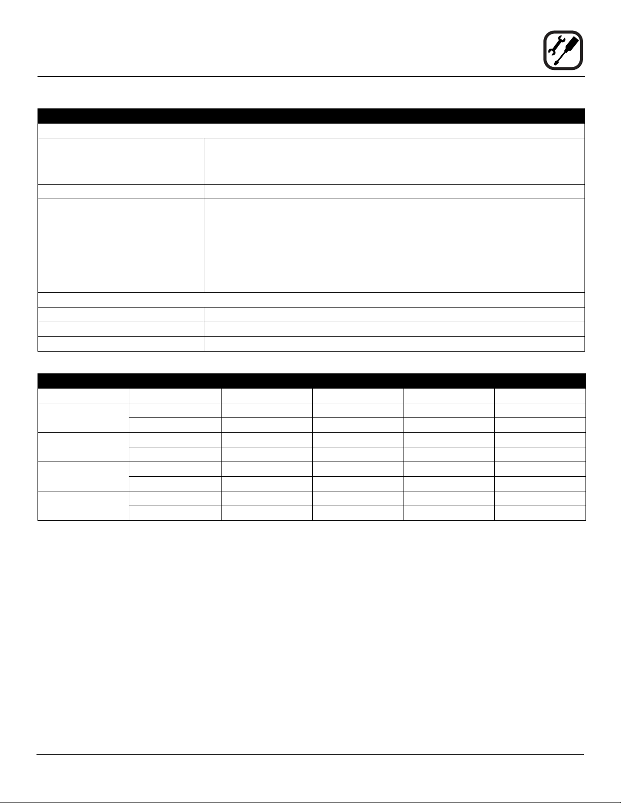
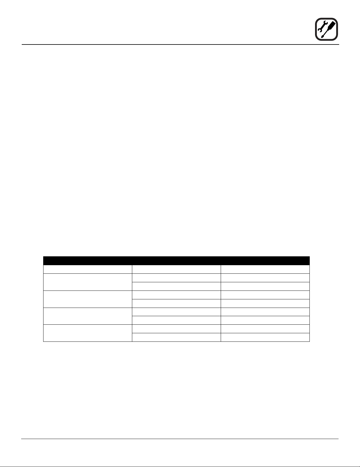
RATINGS - GAS OVENS
Model Gas Type Input Voltage Phase Amps
BLCP-61G Natural 58,000 BTU 115 1 9
Propane 58,000 BTU 11 5 1 9
BLCP-101G Natural 87,000 BTU 115 1 9
Propane 87,000 BTU 11 5 1 9
BLCP-102G Natural 95,500 BTU 115 1 9
Propane 95,500 BTU 11 5 1 9
BLCP-202G Natural 190,000 BTU 115 1 17
Propane 190,000 BTU 115 1 17
5
Page 8
Installation
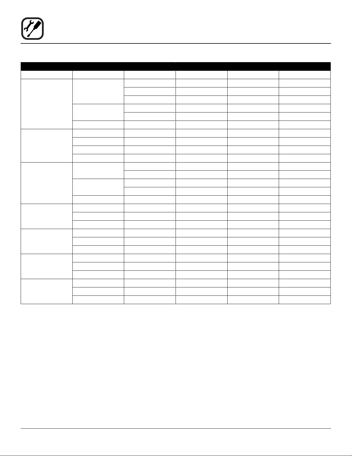
Utility Specications
Model Voltage kW Hz Phase Max Load (amps)
208/230/240
BLCP-23E
Mini Combi
BLCP-6E
Mini Combi
BLCP-10E
Mini Combi
BCP-61E
BLCP-61E
BCP-101E
BLCP-101E
BCP-102E
BLCP-102E
BCP-202E
BLCP-202E
400/415
440/480 5.4/6.5 50/60 2AC 15
208 4.6 50/60 1 23
240 6.1 50/60 1 26
208 6.9 50/60 3 20
240 9.2 50/60 3 23
208/230/240
400/415
440/480 10.4/12.4 50/60 3AC 18
208 9 60 3 25
240 9 60 3 22
480 9 60 3 11
208 18 60 3 50
240 18 60 3 44
480 18 60 3 22
208 27 60 3 75
240 27 60 3 65
480 27 60 3 33
208 60 60 3 167
240 60 60 3 145
480 60 60 3 73
ELECTRICAL RATINGS
2.7/3.3/3.6 50/60 1NAC 15
2.7/3.3/3.6 50/60 2AC 15
5.4/6.6/7.2 50/60 3AC 30
6.6/7.2 50/60 2NAC 15
5.4/5.8 50/60 2AC 15
10.4/12.7/13.8 50/60 3AC 34
10.4/12.7/13.8 50/60 3NAC 34
12.7/13.8 50/60 3NAC 20
12.7/13.8 50/60 3AC 20
6
Page 9
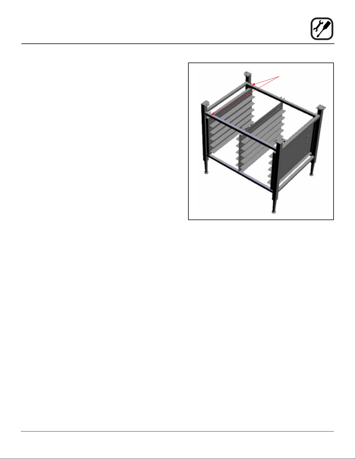
Your Blodgett COMBI oven has been shipped with black
plastic caps on the corners of its base. In order to mount
your oven to its stand, please do the following:
1. Remove the stand from the packaging. Install the
casters or feet into the base of the stand. If inserting
casters ensure that the locking casters are at the front
of the stand, see gure. Place the stand upright in an
area readily available.
2. Remove all packaging from the oven, so that the oven
can be picked up.
3. Remove the black plastic caps on each corner by
removing the two screws holding them on. Do NOT
discard these screws; they will be used to mount the
oven to the stand.
4. Position the oven over the stand and align the corner
brackets on the stand with the holes on the oven.
5. Use the screws from the plastics caps to mount the
oven to the stand.
Installation
Oven Assembly to Stand
Note difference in rail
placement
Front of stand
6. The oven has now been properly fastened to the
stand.
Figure 1
7
Page 10
Installation
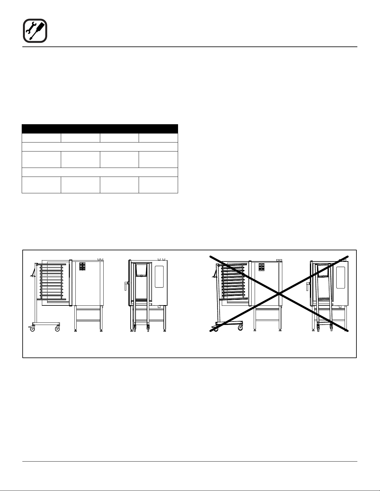
Oven Location and Leveling
The well planned and proper placement of your oven will
result in long term operator convenience and satisfactory
performance.
Certain minimum clearances must be maintained between the oven and any combustible or non-combustible
construction.
MINIMUM REQUIRED CLEARANCES
Size Left Right Back
Electric Ovens
61, 101,
102 & 202
Gas Ovens
61, 101,
102 & 202
2.75”
(70mm)
2.75”
(70mm)
2.75”
(70mm)
2.75”
(70mm)
2”
(50mm)
2”
(50mm)
Strong sources of heat such as hotplates, tilting frying
pans, deep fat fryers, etc. should not be placed near the
oven, especially near its right side. An optional side heat
shield is available.
In addition, the following clearances are recommended
for servicing.
• Oven body sides - 12” (30cm)
• Oven body back - 12” (30cm)
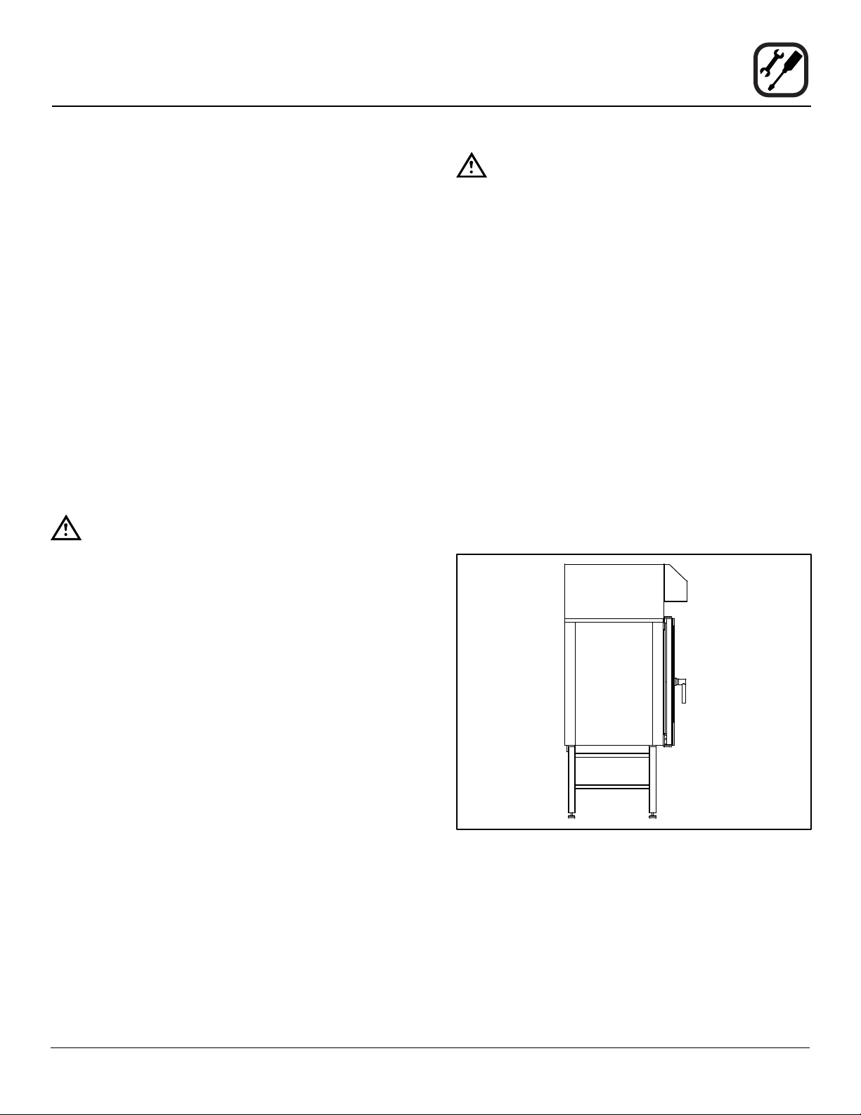
To ensure that the oven functions correctly when installed,
it should be placed upright and level (horizontally). This is
measured at the front and side edge of the roof. The oven
can be levelled using the adjusting screws on the stand or
on the legs of table models. The height of the oven should
also be adjusted to t the trolley for rack.
Correct Installation Incorrect Installation
Figure 2
8
Page 11
Installation
Plumbing Connections
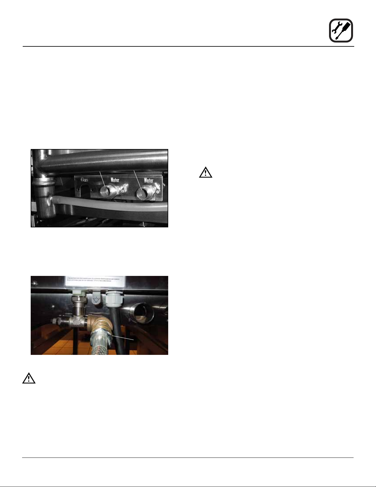
WATER CONNECTION
Blodgett BCP/BLCP ovens have two water connections.
Both are located at the back of the unit.
BCP/BLCP-61, 101, 102 and 202 models
• 1 connection for raw water for the condensation jet.
• 1 connection for steam generation and the Combi
Wash jet in the oven chamber. Must meet the re-
quirements applying to water supplied to household
appliances.
Quench
Steam
Figure 3
To facilitate cleaning and servicing, the oven should be
connected with an approved exible 3/4” hose. Permanent installations should be tted with a stop-tap and a
non-return valve.
Before connecting the oven to water, ush the tubes
thoroughly. Connect the oven.
DRAIN CONNECTION
Blodgett ovens are equipped with a drain system that removes surplus water from the oven chamber. This may
be condensed water from the products, or it may occur
when the oven chamber is cooled down with cold water,
or when the oven chamber is cleaned.
WARNING!!
Connection must be carried out by an authorised plumber, to an open or closed drain.
The drain must never end directly beneath the
oven.
The drain must be of stainless steel or an equally temperature-resistant material, have a diameter of at least 2”
(49 mm) and a fall of at least 3° or 5%.
BLCP-23, 6 and 10 Mini Combi models
• 1 water connection. Must meet the requirements applying to water supplied to household appliances.
Water
connection
Figure 4
WARNING!!
If the water temperature exceeds 70°F (21°C),
problems with regard to Combi Optima calibration and cooling of the oven may occur.
The water connection must be carried out by
an authorized plumber in accordance with
existing local codes.
Clogged up water lters and dirt in the solenoid valves are not covered by the warranty.
9
Page 12
Installation
Plumbing Connections
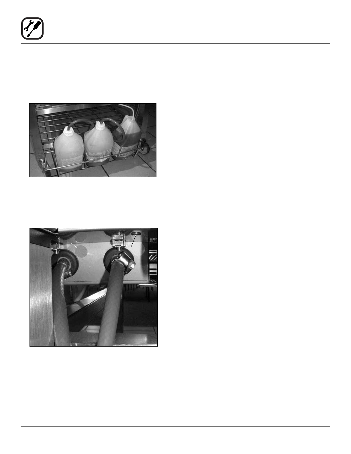
CLEANING & DELIMING CHEMICAL
1. BCP/BLCP-61, 101, 102 and 202 ovens only. The
oven is supplied with a chemical bottle holder. The
holder can be afxed to either side of the oven. Place
it on the stand crossmember.
Figure 5
2. Connect the supplied detergent tubes (red and blue)
to the underside of the oven near the rear. Connect
the blue hose to the tting with the blue sticker and
the red hose to the tting with the red sticker.
3. Insert the blue and red hoses into the proper bottles.
Red is for detergent, blue is for rinse aid.
4. BCP only - The last line is for the delimer. This is the
tan colored tube protroding from the bottom of the
oven. Cut the tubing to the proper length, if needed,
and place the tubing into the delime bottle.
NOTE: If the tube is cut to length, remove the stain-
less steel weight from the end of the tube
and reinsert.
Blue Sticker
Red Sticker
Red Tube
Blue Tube
Figure 6
10
Page 13
ELECTRICAL CONNECTION
NOTE: Electrical connections must be performed by a
qualied installer only.
Before making any electrical connections to these appli-
ances, check that the power supply is adequate for the
voltage, amperage, and phase requirements stated on
the rating name plate mounted on the appliance.
1. The rating plate is located on the right side of the
oven.
An approved plug outlet or a safety cutout must be located close to the oven so that the oven can be disconnected
during installation and repair. The safety cutout must be
able to cut off all poles with a total distance of break of at
least 3 mm.
All appliances must be installed in accordance with Local
or National Electrical codes.
The wiring diagram is located in the motor compartment.
NOTE: Disconnect the power supply to the appliance
before servicing.
WARNING!!
Improper installation may invalidate your warranty.
Electric Models
A strain relief for the power supply cord is provided. The
installer must supply a cord that meets all Local and National installation standards.
Gas Models
U.S. and Canadian Installations
A power cord (115V units only) is supplied with a plug attached. Plug the power cord into the desired receptacle.
NOTE: The BLCP-202G must be hard wired.
This oven model uses a variable frequency inverter drive.
Appliances that use variable frequency inverter drives
produce high frequency noise and require lters and
shielded motor cabling. This causes higher leakage current toward Earth Ground. Especially, at the moment of
switching ON this can cause an inadvertent trip of the appliance’s ground fault interrupter (GFCI). Some GFCIs
are more sensitive than others. Blodgett has qualied the
Pass and Seymour brand, part number 2095, 20 A, 125
VAC, 60 Hz, specication grade GFCI duplex receptacle
as being immune to the variable frequency inverter drive’s
noise. Blodgett recommends using this specic GFCI for
this model oven.
Installation
Electrical Connection and Ventilation
WARNING!!
If the supply cord is damaged, it must be replaced by a special cord or assembly available
from the manufacturer or its service agent.
VENTILATION
Blodgett BCP/BLCP ovens are equipped with an open/
direct exhaust system that removes surplus humidity from
the oven chamber. The exhaust system has an electrically
operated damper.
The ventilation motor can be controlled directly from the
oven. This means that the ventilation starts when a program is started and runs for 10 minutes after the program
is completed.
The exhaust tube can be connected to a ventilation sys-
tem. In that case, a special extraction funnel is tted to
avoid suction directly from the oven chamber. This extraction funnel can be ordered from Blodgett.
If an extraction hood is installed in the ceiling above the
oven, it should project 20” (50 cm) over the front of the
oven.
Figure 7
11
Page 14
Installation
Gas Connection
GAS PIPING
A properly sized gas supply system is essential for maximum oven performance. Piping should be sized to provide a supply of gas sufcient to meet the maximum demand of all appliances on the line without loss of pressure
at the equipment.
Example:
NOTE: BTU values in the following example are for
natural gas.
You purchase a BLCP-61G to add to your existing cook
line.
1. Add the BTU rating of your current appliances.
Pitco Fryer 120,000 BTU
6 Burner Range 60,000 BTU
Deck Oven 50,000 BTU
Total 230,000 BTU
2. Add the BTU rating of the new oven to the total.
Previous Total 230,000 BTU
BLCP-61G 40,900 BTU
New Total 270,900 BTU
3. Measure the distance from the gas meter to the cook
line. This is the pipe length. Let’s say the pipe length
is 40’ (12.2 m) and the pipe size is 1” (2.54 cm).
4. Use the appropriate table to determine the total capacity of your current gas piping.
The total capacity for this example is 375,00 BTU. Since
the total required gas pressure, 270,900 BTU is less than
375,000 BTU, the current gas piping will not have to be
increased.
NOTE: The BTU capacities given in the tables are for
straight pipe lengths only. Any elbows or other
ttings will decrease pipe capacities. Contact
your local gas supplier if you have any questions.
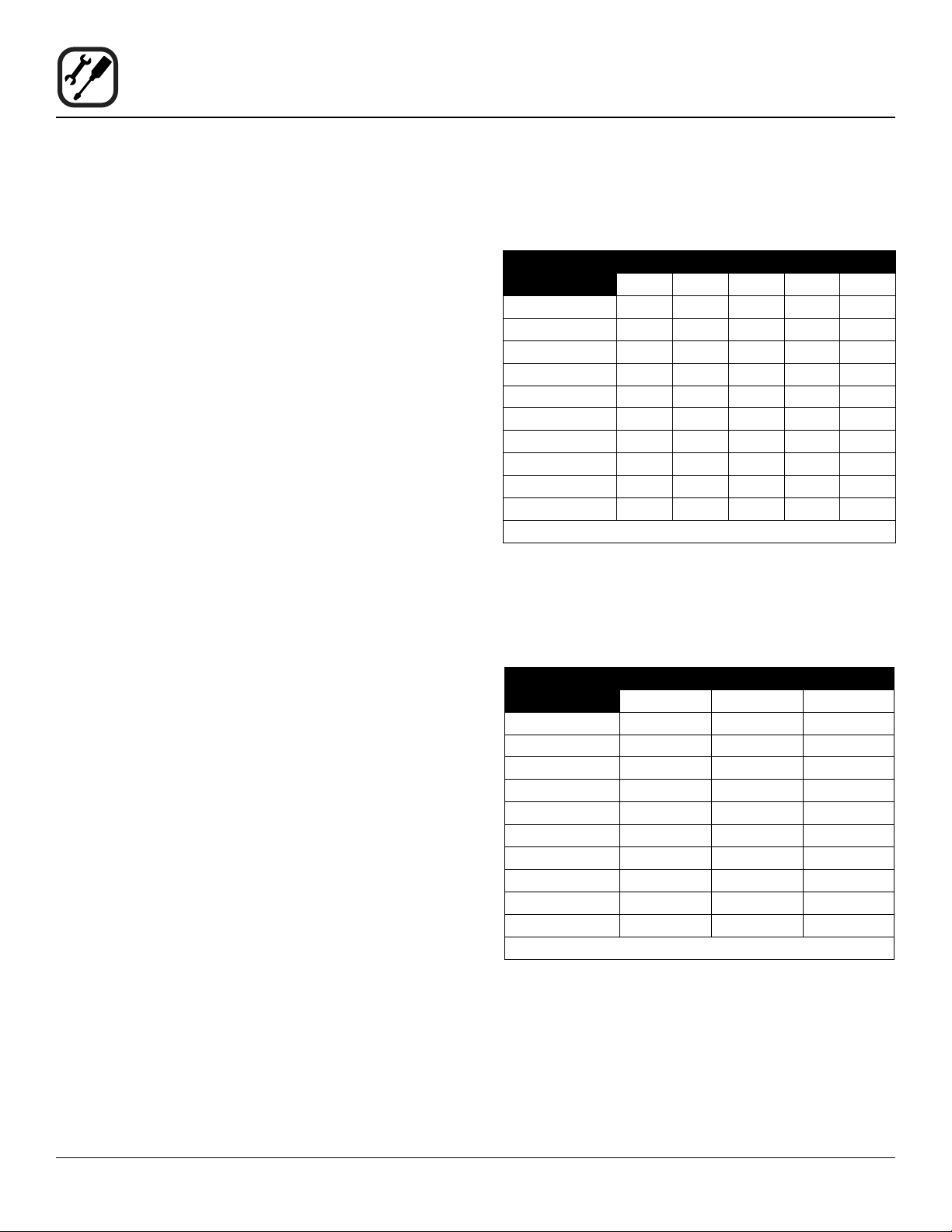
Maximum Capacity of Iron Pipe in Cubic Feet of
Natural Gas Per Hour
(Pressure drop of 0.5 Inch W.C.)
PIPE
LENGTH (FT)
10 360 680 1400 2100 3950
20 250 465 950 1460 2750
30 200 375 770 1180 2200
40 170 320 660 990 1900
50 151 285 580 900 1680
60 138 260 530 810 1520
70 125 240 490 750 1400
80 118 220 460 690 1300
90 110 205 430 650 1220
100 103 195 400 620 1150
From the National Fuel Gas Code Part 10 Table 10-2
Maximum Capacity of Pipe in Thousands of
BTU/hr of Undiluted L.P. Gas at 11” W.C.
(Pressure drop of 0.5 Inch W.C.)
PIPE
LENGTH (FT)
10 608 1146 3525
20 418 788 2423
30 336 632 1946
40 287 541 1665
50 255 480 1476
60 231 435 1337
70 215 404 1241
80 198 372 1144
90 187 351 1079
100 175 330 1014
From the National Fuel Gas Code Part 10 Table 10-15
NOMINAL SIZE, INCHES
3/4” 1” 1-1/4” 1-1/2” 2”
OUTSIDE DIAMETER, INCHES
3/4” 1” 1-1/2”
12
Page 15
PRESSURE REGULATION AND TESTING
The gas pressure to the appliance must be rated for each
appliance while the burners are on. A sufcient gas pressure must be present at the inlet to satisfy these conditions. Refer to the table below for correct gas pressure.
Each appliance has been adjusted at the factory to oper-
ate with the type of gas specied on the rating plate.
Each oven is supplied with a regulator to maintain the
proper gas pressure. The regulator is essential to the
proper operation of the oven and should not be removed.
DO NOT INSTALL AN ADDITIONAL REGULATOR
WHERE THE UNIT CONNECTS TO THE GAS SUPPLY
UNLESS THE INLET PRESSURE IS GREATER THAN
14” W.C. (1/2 PSI) (37mbar).
The oven and its individual shutoff valve must be disconnected from the gas supply piping system during any
pressure testing of that system at test pressures in excess of 1/2 psig (3.45kPa).
The oven must be isolated from the gas supply piping
system by closing its individual manual shutoff valve during any pressure testing of the gas piping system at test
pressures equal or less than 1/2 psig (3.45kPa).
Installation
Gas Connections
Prior to connecting the appliance, gas lines should be
thoroughly purged of all metal lings, shavings, pipe
dope, and other debris. After connection, the appliance
must be checked for correct gas pressure.
U.S. and Canadian Installations
Installation must conform with local codes, or in the absence of local codes, with the National Fuel Gas Code,
NFPA54/ANSI Z223.1-Latest Edition, the Natural Gas Installation Code CAN/CGA-B149.1 or the Propane Installation Code, CAN/CGA-B149.2 as applicable.
General Export Installations
Installation must conform with Local and National instal-
lation standards. Local installation codes and/or requirements may vary. If you have any questions regarding the
proper installation and/or operation of your appliance,
please contact your local distributor. If you do not have a
local distributor, please call Blodgett Combi at 0011-802658-6600.
GAS PRESSURE
Model Gas Type Inlet Pressure
BLCP-61G Natural 3.2-8.0” W.C.
Propane 5.2-14” W.C.
BLCP-101G Natural 3.2-8.0” W.C.
Propane 5.2-14” W.C.
BLCP-102G Natural 3.2-8.0” W.C.
Propane 5.2-14” W.C.
BLCP-202G Natural 3.2-8.0” W.C.
Propane 5.2-14” W.C.
13
Page 16
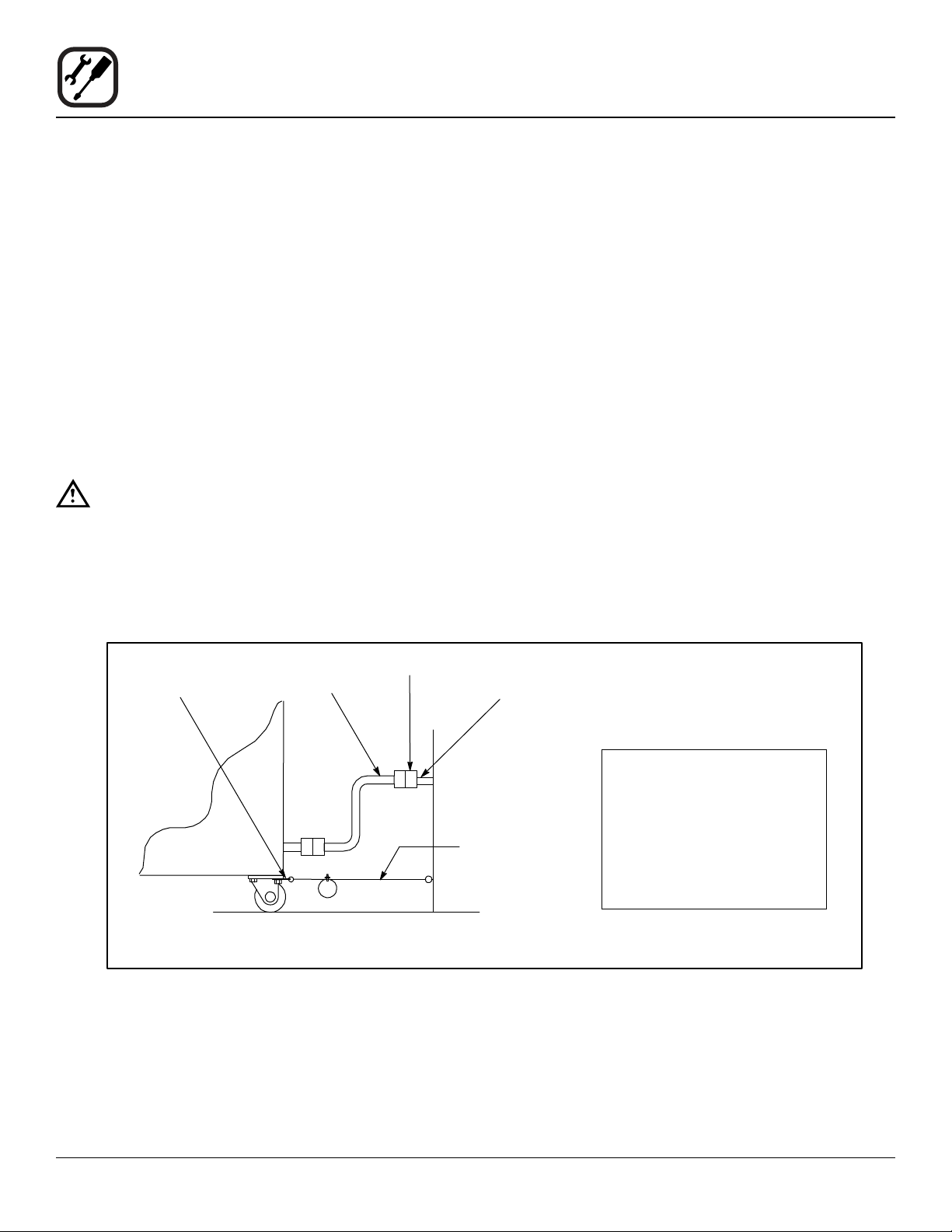
Installation
Gas Hose Restraint
If the appliance is mounted on casters, a commercial exible connector with a minimum of 3/4” (1.9 cm) inside di-
ameter must be used along with a quick connect device.
A restraint must be used to limit the movement of the appliance so that no strain is placed upon the exible connector. The restraint should be fastened to the base frame
of the oven as close to the exible connector as possible.
It should be short enough to prevent any strain on the
connector. With the restraint fully stretched the connector
should be easy to install and quick connect.
The restraint (ie: heavy gauge cable) should be attached
without damaging the building. DO NOT use the gas piping or electrical conduit for the attachment of the permanent end of the restraint! Use anchor bolts in concrete or
cement block. On wooden walls, drive hi test wood lag
screws into the studs of the wall.
WARNING!!
If the restraint is disconnected for any reason
it must be reconnected when the appliance is
returned to its original position.
U.S. and Canadian installations
The connector must comply with the Standard for Connectors for Movable Gas Appliances, ANSI Z21.69 or
Connectors For Moveable Gas Appliances CAN/CGA-
6.16 and a quick disconnect device that complies with the
Standard for Quick-Disconnect Devices for Use With Gas
Fuel, ANSI Z21.41 or Quick Disconnect For Use With Gas
Fuel CAN 1-6.9. Adequate means must be provided to
limit the movement of the appliance without depending
on the connection and the quick disconnect device or its
associated piping.
A drip leg must be used at each appliance. Refer to
NFPA54/ANSI Z223.1 - Latest Edition (National Fuel Gas
Code) for proper drip leg installation.
General export installations
Installation must conform with Local and National instal-
lation standards. Local installation codes and/or requirements may vary. If you have any questions regarding the
proper installation and/or operation of your appliance,
please contact your local distributor. If you do not have a
local distributor, please call Blodgett Combi at 0011-802658-6600.
Attachment Plate
(secure with leg mount bolt)
Quick Connect
Gas Hose
Restraint
Installation of Gas Hose and Restraint
(Single Section Shown)
Figure 8
Gas Supply Line
IMPORTANT: Cable restraint should
be fastened as close as possible
to the exible connector and short
enough to prevent any strain on the
exible connector.
At maximum stretch of shortened
restraint, the exible connector
should be easy to install and quick
to connect.
14
Page 17

WARNING!!
Final check list must be performed by a quali-
ed installer only.
OVEN EXTERIOR
1. Check that the oven has not been damaged in transit
(dents, scratches, etc.)
2. Check/adjust the height and check that the oven is
placed level (horizontally)
3. Check/adjust oven door
CONNECTIONS
1. Check for correct water connection
2. Turn on water supply
3. Check for leaks
4. Turn off water supply
Installation
Final Check Lists
OVEN INTERIOR
1. Check that lter housing is mounted correctly
2. Check interior light
3. Clean the oven
CONTROL
1. Check and adjust, if necessary, each of the preset
values
2. Heat up the oven at 480°F (249°C) for approximately
5 minutes.
5. Check and clean dirt lter
6. Turn on water supply again
7. Check hand shower
8. Check for correct electrical connection
9. Check for correct gas connection (if applicable)
10. Check connection to drip tray
11. Check for correct mounting of drip tray
12. Check for correct fall of hose from drip tray, and check
for leaks
13. Check for correct exhaust and drain connection
14. Clean the oven
15. Apply steel oil
15
Page 18

Operation
Safety Information for Gas Ovens
The information contained in this section is provided for
the use of qualied operating personnel. Qualied operating personnel are those who have carefully read the information contained in this manual, are familiar with the
functions of the oven and/or have had previous experience with the operation of the equipment described. Adherence to the procedures recommended herein will assure the achievement of optimum performance and long,
trouble-free service.
Please take the time to read the following safety and operating instructions. They are the key to the successful
operation of your Blodgett oven.
SAFETY TIPS
For your safety read before operating
What to do if you smell gas:
• DO NOT try to light any appliance.
• DO NOT touch any electrical switches.
• Use an exterior phone to call your gas supplier im-
mediately.
• If you cannot reach your gas supplier, call the re
department.
What to do in the event of a power failure:
• Turn all switches to off.
• DO NOT attempt to operate the oven until the power
is restored.
NOTE: In the event of a shut-down of any kind, allow a
ve (5) minute shut off period before attempting
to restart the oven.
General safety tips:
• DO NOT use tools to turn off the gas control. If the
gas cannot be turned off manually do not try to re-
pair it. Call a qualied service technician.
• If the oven needs to be moved for any reason, the
gas must be turned off and disconnected from the
unit before removing the restraint cable. Reconnect
the restraint after the oven has been returned to its
original location.
• DO NOT remove the control panel cover unless the
oven is unplugged.
16
Page 19
Operation
Blodgett Programmable Control Introduction
The BCP/BLCP ovens include the versatile Blodgett Programmable control. The control features:
• Multiple cooking modes include hot air, combi with
CombiOptima, reheating/regenerating, steaming,
low-temperature steaming, forced steaming, proofing, cooling, and preheating
• CombiOptima automatically measures and controls
the humidity level in the oven, helping to retain the
appearance and juiciness of the product.
• Easy to use touch panel with crystal clear TFT display
• Stores up to 200 recipe programs with 10 cooking
stages each. Recipes can be grouped into categories (beef, chicken, cookies, etc.) for easy retrieval.
• External core temperature probe with 3 measuring
points. Ability to run 2 core probes simultaneously.
• Low temperature roast & hold and Delta-T cooking
Figure 9
• Reversible 9 speed fan for optimum baking and
roasting results
• USB port for data, software and recipe transfer
• HACCP quality control enables you to control and
document production. Includes production time, production duration, preparation temperature, and core
temperature.
• CombiNet for monitoring and remote controlling the
oven via computer or internet. Functions include
recipe management, HACCP, service diagnosis and
software updating
• Programmable time delay start
• Automatic service diagnosis
17
Page 20

Operation
Cooking Modes
COMBIOPTIMA MODE
CombiOptima offers you the possibility of adding up to
100% humidity to the oven chamber at temperatures from
160 to 480°F (70 to 250°C).
When using CombiOptima correctly, you minimise shrinkage and enhance the appearance and taste of your product.
Many products contain a large amount of water, increasing the humidity level during cooking. The oven automatically regulates the humidity to maintain the desired level.
Setting the humidity level
1. Use the bottom keys on the left and right to set the
desired humidity level. The blue and red bar indicated
the actual humidity level in the oven cavity. The white
number in the center of the bar indicated the desired
humidty level.
2. Preheat the oven for 5 minutes with the desired humidity content. Depending on the amount of product
in the oven and the desired humidity level and temperature, the desired humidity is typically reached after 1 to 5 minutes.
Tips for setting the humidity level
• To make gravy when braising meat, apply 70 to 80%
humidity at 300-325°F (145-65°C).
• For poaching sh, poultry and crispy vegetables, apply 70 to 95% humidity at 150-250°F (70-120°C).
• For short cook times and products, such as herbmarinated cuts of meat and fresh vegetables, use
70% humidity at 375°F (190°C ). Despite the short
cook time, products such as cook very gently.
NOTE: If the bar is all red, the oven containss 0%
humidity. If the bar is all blue, the oven contains 100% humidity.
Humidty level
setpoint
If the oven is not connected to a soft water plant,
CombiOptima cannot function properly.
Actual humidty
level bar
Press this key to
decrease humidity level
Press this key to
increase humidity level
Figure 10
18
Page 21

Operation
Cooking Modes
STEAM MODE
The steam mode provides 100% humidity in the cooking
chamber. Use the steam mode for the following applications:
Low Temperature Steaming
Steaming at 150-195°F (65-90°C) is recommended for
delicate products such as sh.
Steaming fresh vegetables such as carrots, asparagus,
and beans at 175°F (80°C) for 5 to 10 minutes produces
products that keep their color and crispness.
Traditional Steaming
Steaming at 208-212°F (98-100°C) is recommended for
all kinds of root vegetables, potatoes, pasta, rice and
meat.
Forced Steaming
Steaming at 250°F (120°C) can be used for vegetables
that need further processing and for faster preparation of
pasta, rice, hard root vegetables and frozen vegetables.
Forced steaming should be used with care.
Tips for Using the Steam Mode
• We recommend that you start the steaming process
8 minutes before you place the products in the oven
chamber. For food safety reasons, the oven automatically checks the water in the steam generator.
If the water temperature is below 150°F (65°C), the
tank is emptied, relled and the water is heated.
• To get the oven ready for production quickly and to
ensure a perfect start of the steaming process, we
recommend that you cool down the oven chamber to
175°F (80°C). To lower the temperature quickly, use
the Cool Down mode and open the door.
If the oven is not connected to a soft water plant, the
Steam mode cannot function properly.
RETHERM MODE
Reheating is a very gentle process 70-350°F (20-180°C).
The program operates with low fan speed and adds a
carefully calculated amount of humidity which maintains
the nice appearance and taste of the product.
Tips for Using Retherm
• To quicker retherming, products should not be covered.
• For best results, use a core temperature probe.
• When retherming sous-vide products, follow supplier
recommendations.
Recommended Times & Temperatures
• 8 to12 minutes at 285°F (140°C) for plated meals
with rice, meat and vegetables.
• 40 to 60 minutes at 250-285°F (120-140°C) for
whole roasts, stews and sauces.
• 20 to 30 minutes at 250°F (120°C) for pasta and
rice.
PROOFING MODE
The oven is designed to maintain the perfect humidity
for all products that need to be proofed before they are
baked.
For your convenience, the Blodgett BCP/BLCP has a
preset program called “Semiautomatic Bread”. In this program the bread is proofed and baked in the same process.
Recommended Times & Temperatures
• Low temperature and long proong time of 90°F
(32°C) for 45 minutes for 14-28 ounces (400-800g)
loaves of bread
• High temperature and short proving time 100°F
(38°C) for 25 minutes for 2-7 ounce (60-200g) rolls
and baguettes.
PREHEAT MODE
In this mode the oven will preheat to 575°F (300°C) for 15
minutes. The oven will then automatically lower to 480°F
(249°C) to protect the advanced electronic components.
We recommend preheating the oven 80-100°F (27-38°C)
above the cook temperature.
19
Page 22
Operation
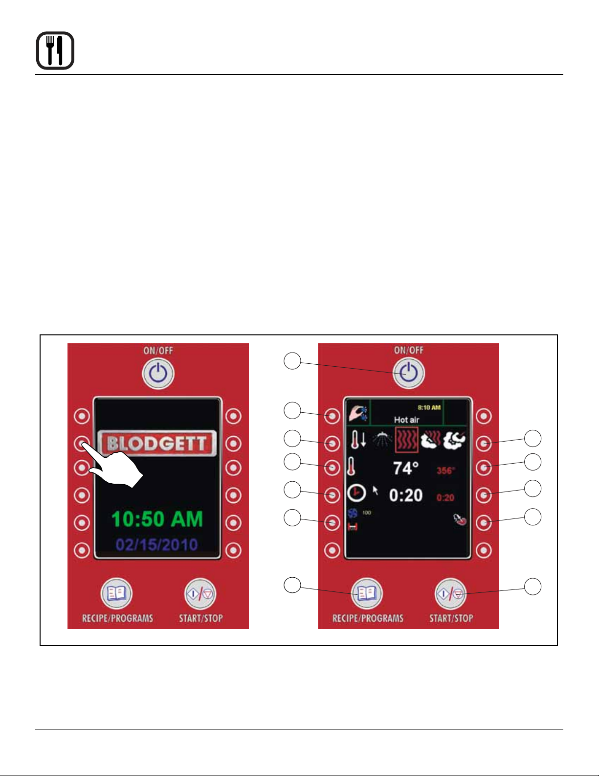
Welcome Screen and Work Menu
The welcome screen will appear when you power up your
BCP/BLCP oven.
1. Press the any of the 6 keys on either side of the control to access the WORK Menu.
WORK MENU
1. MAIN POWER SWITCH - controls power to the oven
2. MAIN MENU KEY - press to move to main menu
3. LEFT MODE SELECTION KEY - press to select
mode to the left.
4. LEFT OVEN TEMP KEY - press to decrease set temperature.
5. LEFT COOK TIME KEY - press to decrease the set
cook time
6. FAN & VENT KEY - press to access fan and vent submenus
7. PROGRAM KEY - press to access program menu
8. RIGHT MODE SELECTION KEY - press to select
mode to the right.
9. RIGHT OVEN TEMP KEY - press to increase set temperature.
10. RIGHT COOK TIME KEY - press to increase the set
cook time
11. CORE PROBE KEY - press to access core probe setting submmenu
12. START/STOP KEY - press to begin or cancel a cook
cycle
1
2
3
4
5
6
7
Welcome Screen Work Menu
Figure 11
8
9
10
11
12
20
Page 23

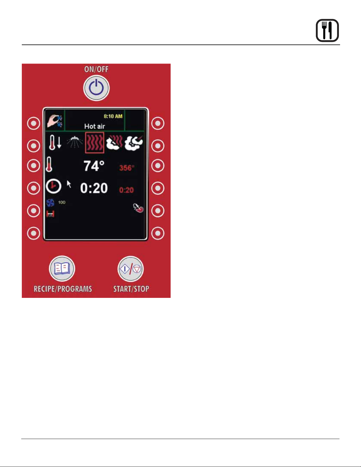
MODE SELECTION
1. Use the keys on the right and left of the mode selection icons to select the desired mode.
NOTE: The selected icon will apper inside a red box
in the center of the screen.
Operation
Manual Cooking
Setting Humidty Level in CombiOptima
If CombiOptima is selected you will need to enter the desired humidity level.
Press this key to
scroll to the left
Hot Air Combi
Optima
Press this key to
scroll to the right
Choose from the following oven modes:
Steam Retherm Proong Preheat Cool Down Combi
Wash
Figure 12
21
Page 24
Operation
Manual Cooking
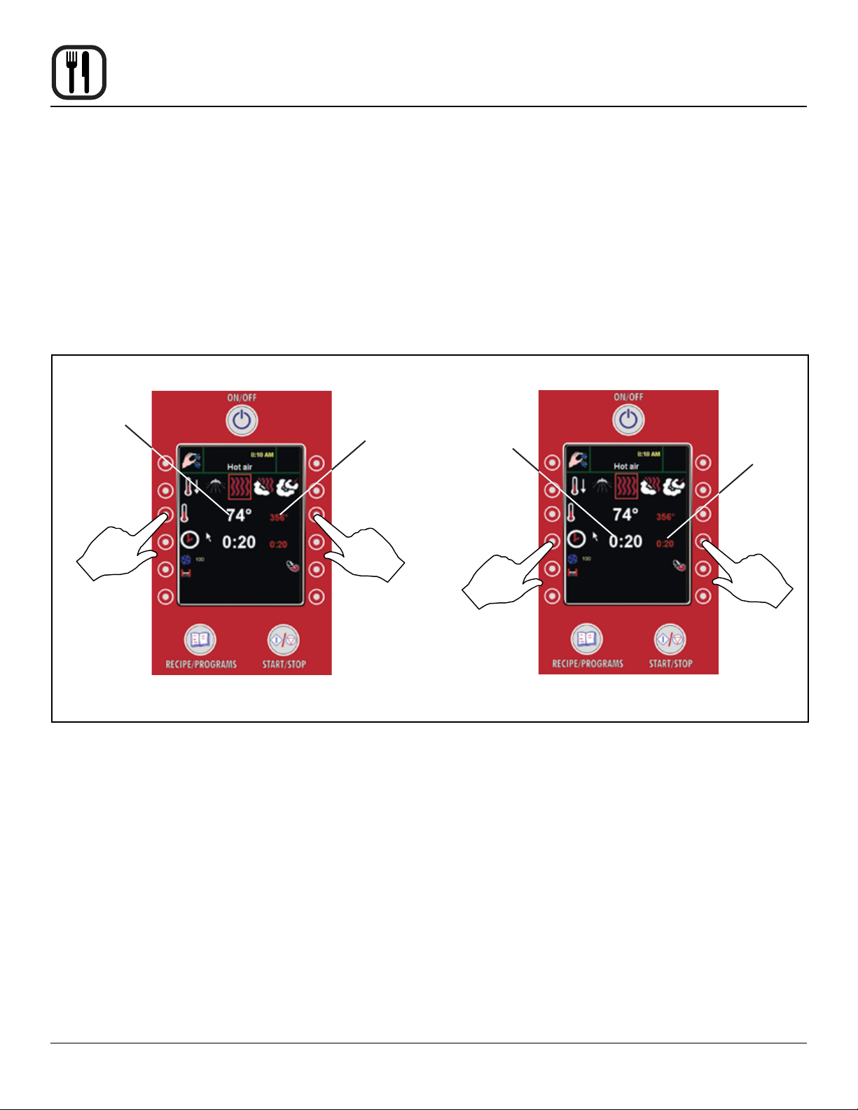
SETTING THE COOK TEMPERATURE
1. Use the 3rd keys down on the right or left to set the
desired cook temperature. The large white number in
the center of the screen displays the actual oven temperature. The smaller red number on the right of the
screen displays the set temperature.
Actual oven
temperature
Oven set
temperature
SETTING THE COOK TIME
1. Use the 4th keys down on the right or left to set the
desired cook time. For continuous operation, press
the left key until the display shown no time.
The smaller red number on the right of the screen
displays the set cook time.
Once the cook cycle is activated, the large white
number in the center of the screen displays the time
remaining.
Time
remaining
Oven
set time
Press this key to
decrease set
temperature
Setting the Cook Temperature
Press this key to
increase set
temperature
Figure 13
Press this key
to decrease
set time
Press this key
to increase
set time
Setting the Cook Time
22
Page 25
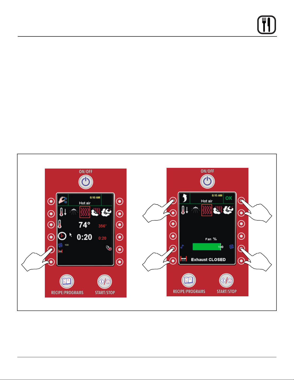
SETTING THE FAN SPEED
The fan function is active in HOT AIR, STEAM and RETHERM only. In all other modes, the fan is controlled automatically by the oven.
1. Press the FAN and VENT key to access the FAN/
VENT submenu.
Operation
Manual Cooking
Tips for setting fan speed
• A fan speed between 20 and 50% is recommended
for puff pastry, Danish pastry, cakes and small
products as well as in the Delta-T and Cook & Hold
modes.
2. Use the 5th keys down on the right or left to set the
desired fan speed.
NOTE: Note that the fan wheel is reversible. It will
run clockwise for a few minutes, then reverse
and run counterclockwise. This creates an
even bake pattern.
Work Menu
Press this key
to cancel and
return to
WORK Menu
• You should add 1 to 2 minutes of preparation time
for each 1/2 hour when low fan speed is used.
• Fan speeds between 50% and 90% are recommended for particularly juicy end products that can
accept longer cook times.
• Fan speeds below 50% cannot be used at temperatures above 390°F (200°C).
Fan/Vent Submenu
Press this
key to
save settings
Press this
key to
access
FAN/VENT
submenu
Press this key
to increase
fan speed
Figure 14
23
Press this
key to
decrease
fan speed
Page 26

Operation
Manual Cooking
SETTING THE VENT POSITION
It is only possible to set the exhaust function in the
HOT AIR mode. In the other modes, the exhaust function
is controlled automatically by the oven.
1. Press the VENT key to toggle between Vent Open or
Vent Closed.
Tips for setting vent position
• Open exhaust is recommended for bread and pastry,
as well as roasting meat and to achieve a grill effect.
TO RETURN TO WORK MENU
1. Press the OK key on the top right to save your settings and return to the WORK Menu. Press the top
right key to return the the WORK Menu without saving
your changes.
Fan/Vent Submenu Manual Cook Screen
TO INITIATE MANUAL COOK CYCLE
1. From the WORK Menu, press the START/STOP key
located on the bottom left side of the control to initiate
the cook cycle.
2. The square around the mode will ash and the display
counts down the cook time. The cook time, temperature, fan speed and vent position may be changed
during the cook cycle.
In Hot Air mode, press and hold the button on the
bottom right of the screen to inject steam.
Press any key to turn on the oven lights.
3. When there is one minute left, the computer counts
down from 59 seconds.
4. When the time has expired on the nal stage, an
alarm sounds and a message appears notifying you
that the program is complete. Press the key to the left
of ENTER, or open the door, to silence the alarm.
Press this key
to cancel and
return to
WORK Menu
Press this key to
toggle the vent
open or closed
Press this key
to save settings
Press START/
STOP key
to initiate cook
cycle
Figure 15
24
Page 27

Operation
Core Probe Cooking
All Blodgett BCP/BLCP ovens come standard with one
core temperature probe. It is possible to run two core
probes at the same time. An additional probe may be purchased from your Blodgett dealer.
The core temperature sensor offers three cooking
modes.
• Active
• Delta-T
• Cook & Hold
ENTERING CORE PROBE MODES
Follow this procedure for all three core probe cooking modes.
NOTE: The core probe must be set up prior to activating
a cook cycle.
1. Select the desired cooking mode. Refer to instructions on setting the cooking mode.
2. Set the desired fan speed if applicable. Refer to instructions on setting the fan speed.
3. Set the vent position if applicable. Refer to instructions on setting the vent position.
4. Insert the core probe into the center of the product.
Then plug the probe into the oven at the connector
located in the upper corner of the right side panel.
NOTE: Meat probe on mini combi models are inter-
nal and do not need to be plugged into the
oven.
5. Press the CORE PROBE key on the WORK Menu.
The control displays the Core Probe submenu.
6. Press the key next to the core probe icon. The control
displays the Set Core Probe screen.
The graph on the display illustrates the difference
between the actual oven temperature and core temperature. The blue line represents core temperature
probe 1. Core probe 2 is green. The red line is the
actual oven temperature.
Work Menu
Press this key to
move to the
Core Probe
submenu
Core Probe Submenu
Core probe
status graph
Press this key
to select the
rst core probe
Figure 16
25
Page 28
Operation
Core Probe Cooking
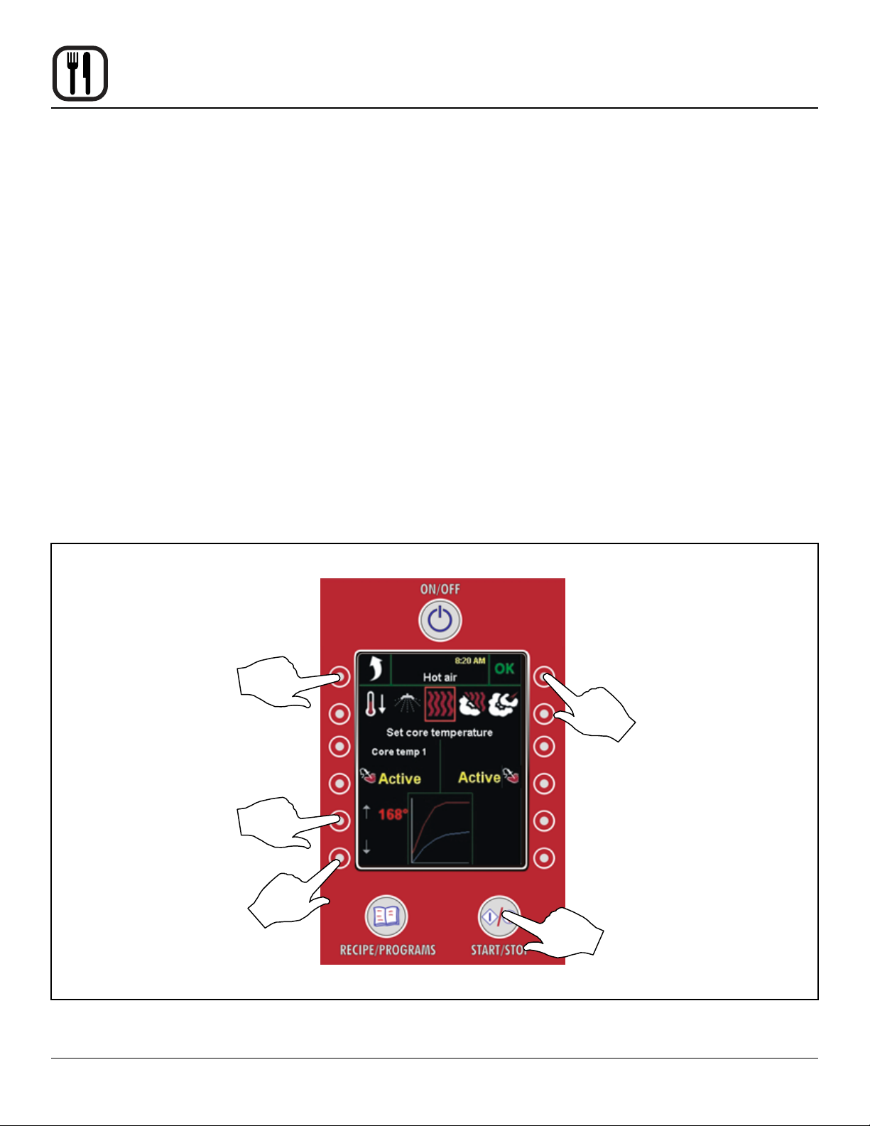
ACTIVE CORE PROBE COOKING
In the active mode, the core probe will notify you when the
product has reached the desired pull temperature. The
cook temperature is constant in the active mode.
1. Follow steps 1-6 on the page 25 to enter the core
probe cooking screens.
2. Use the keys on the left of the display to set the desired core probe pull temperature. The core probe set
temperature is displayed in red.
3. Press the OK key to save the save the desired core
probe temperature.
4. Press the START/STOP key to start the core probe
cook cycle.
5. When the product has reached the desired core temperature an alarm sounds and the display reads ENTER. Press the key next to ENTER, or open the door,
to silence the alarm.
6. Unplug the core probe and remove the product.
Set Core Probe Screen
COOKING WITH TWO CORE PROBES
When one of the probes reaches the desired core temperature, an alarm sounds and a ENTER appears in the
display.
1. Press the key next to ENTER, or open the door, to
silence the alarm.
2. Take out the product and close the door.
3. The oven continues until the second probe reaches
the desired core temperature.
Press this key to cancel
and return to WORK Menu
Press this key to raise
probe temp
Press this key to
lower probe temp
Press this key to save
your settings
Press this key to start the
core probe cook cycle
Figure 17
26
Page 29

DELTA-T COOKING
In the Delta-T mode the oven temperature adjusts relative
to the actual core temperature of the product. Delta-T provides gentle cooking resulting in a tender, juicy product.
Cooking with Delta-T reduces shrinkage by up to 20%
compared to traditional modes of cooking.
1. Follow steps 1-6 on page 25 to enter the core
probe cooking screens.
2. Press the CORE PROBE key on the WORK Menu.
The control displays the Core Probe submenu.
3. Press the Core Probe key twice to access the Delta-T
cooking screen.
4. Use the keys on the left of the display to set the desired core probe pull temperature. The core probe set
temperature is displayed in red.
5. Press the OK key to save the save the desired core
probe temperature.
Operation
Core Probe Cooking
7. When the product has reached the desired core temperature an alarm sounds and the display reads ENTER. Press the key next to ENTER, or open the door,
to silence the alarm.
8. Unplug the core probe and remove the product.
Tips for Delta-T Cooking
• For best results start with an oven temperature of
85-100°F (30-40°C).
• HOT AIR mode is recommended for very fatty and
small roasts. STEAM mode is recommended for
large hams with bones. RETHERM mode is recommended for poultry and other lean pieces of meat.
Recommended Core Temperatures
• Rare 125-135°F (52-57°C)
• Medium 140-145°F (59-62°C)
6. Press the START/STOP key to start the Delta-T cook
cycle.
Set Core Probe Screen Delta-T Cooking Screen
Press this key
to raise probe
temp
Press this
key twice
to access
the Delta-T
screen
Press this key to
lower probe temp
• Well Done 160-185°F (72-85°C)
Press this key
to save your
settings
Press this key to
start the Delta-T
cook cycle
Figure 18
27
Page 30
Operation
Core Probe Cooking
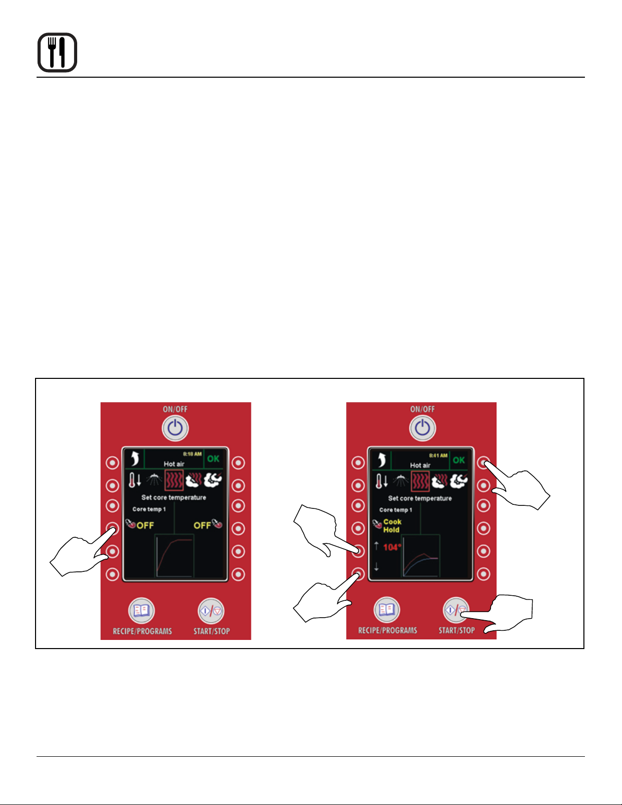
COOK & HOLD
Cook & Hold is an extension of Delta-T cooking. The oven
temperature adjusts relative to the actual core temperature of the product. When the desired core temperature is
reached, the oven adjusts the cavity to maintain the core
temperature, acting as a warming mode. Cook & hold is
suitable for roasting over night when the staff is off duty.
1. Follow steps 1-6 to enter the core probe cooking
screens.
2. Press the CORE PROBE key on the WORK Menu.
The control displays the Core Probe submenu.
3. Press the Core Probe key three times to access the
Cook & Hold cooking screen.
4. Use the keys on the left of the display to set the desired core probe temperature. The core probe set
temperature is displayed in red.
5. Press the OK key to save the save the desired core
probe temperature.
6. Press the START/STOP key to start the Cook & Hold
cook cycle.
7. When the product has reached the desired core temperature the display will read HOLD??? and the oven
will adjust the cavity temperature to maintain the core
probe temperature.
8. Unplug the core probe and remove the product when
ready to serve.
Tips for Using Cook & Hold
• Recommended holding temperature is 140-150°F
(60-65°C). At higher temperatures a gradual dehydration of proteins takes place, the weight of the
meat is reduced and the meat becomes less juicy.
• With a hold temperature of 140-150°F (60-65°C), the
meat can be taken out immediately before carving.
• After being held for 5-6 hours shrinkage increases.
Press this
key three
times to
access the
Cook & Hold
screen
Set Core Probe Screen Cook & Hold Screen
Press this key to
save your settings
Press this key to
raise probe temp
Press this key to
start Cook & Hold
Press this key to
lower probe temp
Figure 19
28
Page 31

Operation
Programmed Cooking
BCP/BLCP ovens can store 200 product programs with
10 cooking stages each. Products are grouped into categories (beef, chicken, bread, etc.) for easy retrieval. Use
the following procedure to cook using a pre-programmed
product recipe.
1. Press the PROGRAM key located on the bottom right
of the control. The Program submenu is displayed.
The right side of the display shows the product categories. The green arrow at the bottom inducates
there are more categories than displayed.
The left side of the display shows the recipes in the
current category
2. If the desired category is not visible, press the key
next to the green arrow to display additional categories.
3. Press the key next to the desired product category.
4. The product programs in the choosen category are
displayed on the right side of the screen. If the category has more than 5 products a scroll key will appear
at the top of the category list. Press this key to scroll
through the product programs in the category.
Program SubmenuBottom of BCP Control
Press this
key to display
additional
categories
Press this key to access
the Program submenu
Press to scroll through
all product programs
within a category
Product
Program
keys
Product
Category
keys
Press this key
to display
additional
categories
Figure 20
29
Page 32
Operation
Programmed Cooking
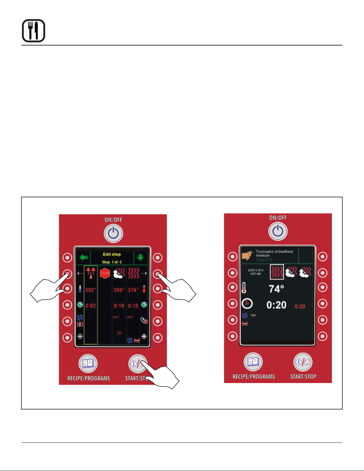
5. Press the key next to the desired product program.
The display changes to the Edit Step screen. This
screen gives the operator the chance to change the
cook temperature, time, fan speed, vent and humidity level (if applicable) for any stage of the program.
Changes made will be for the current bake only. The
program will not be changed for future bakes.
6. Press the START/STOP key to initiate the programmed cook cycle. The display shows the Program
Cooking screen.
NOTE: If the rst stage of the program is a preheat,
an alarm sounds at the end of the stage and
a message appears notifying you that the
preheat is complete. Press the key next to
ENTER to silence the alarm and proceed to
stage 2.
Edit Step Screen Program Cooking Screen
7. The square around the mode for the current stage will
ash and the display counts down the cook time.
8. When there is one minute left in each stage, the computer counts down from 59 seconds.
9. When the time has expired on the nal stage, an
alarm sounds and a message appears notifying you
that the program is complete. Press the key to the left
of ENTER, or open the door, to silence the alarm.
10. The control returns to the WORK Menu.
Press to
return to
settings for
the previous
stage
The yellow box indicated the current
stage in edit mode.
Press to move to
settings for the next
stage
Press to start
product program
Figure 21
30
Page 33

Operation
Programming a Product
Use the following procedure to create a new product program or edit an existing program.
1. Press the MAIN MENU key in the upper left corner to
advance the control to the main menu.
2. Press the EDIT PROGRAM key on the MAIN menu.
If, when one of the functions in the main menu is activated, a screen appears asking for a code, this func-
Work Menu Main Menu
Press to go
to MAIN
Menu
tion is blocked. You need a code to access. Select
enter code, press 876412 and conrm by pressing
OK in the upper right corner.
3. To create a new product recipe, press the NEW RECIPE key. To edit an existing product recipe, follow the
procedure on to select the product program to be edited.
Press to edit or
create a program
Press to create
a new program
Programmed Recipe Screen
Figure 22
31
Page 34

Operation
Programming a Product
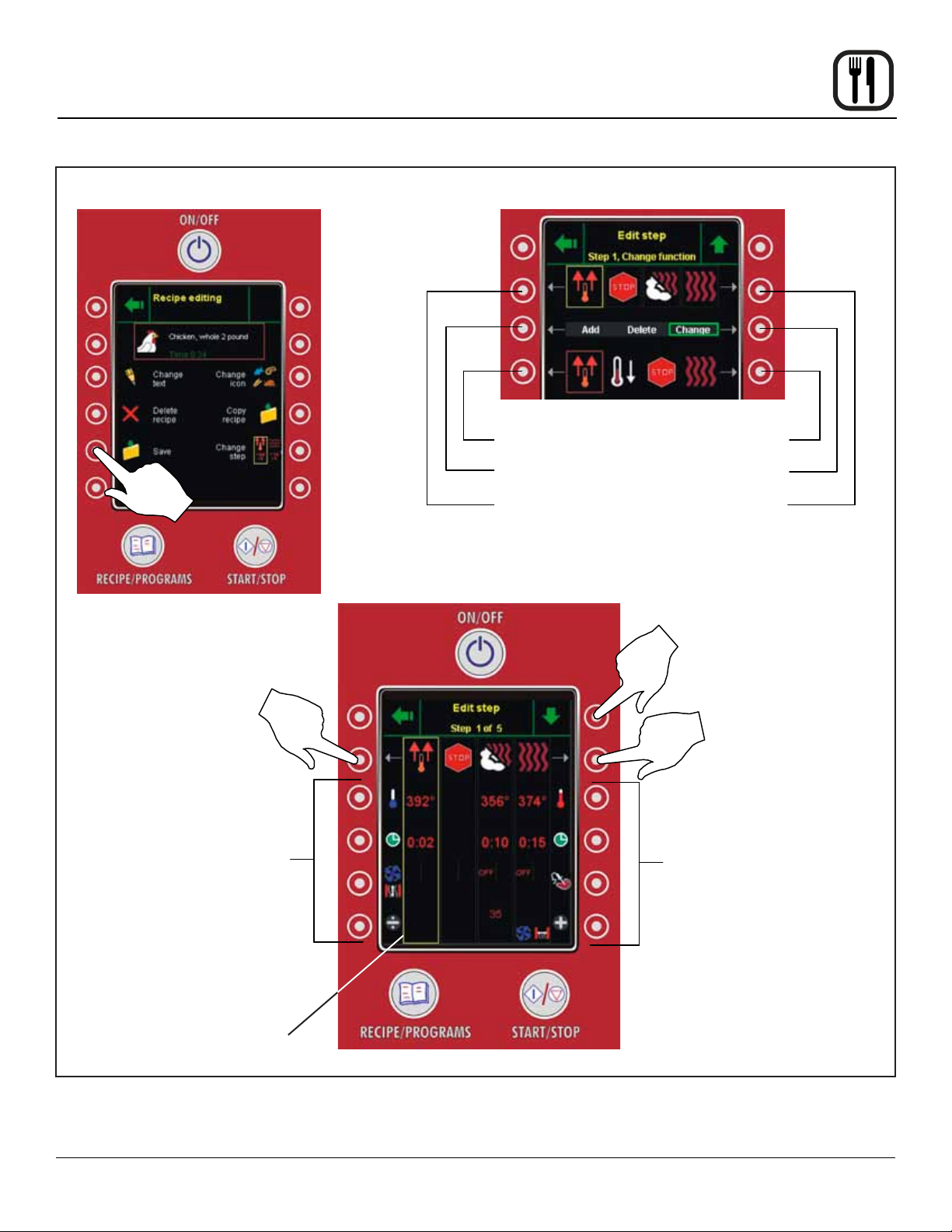
4. The Edit Program screen is displayed. This is the main
screen for creating and editing product programs.
Naming or Renaming the Product Program
5. Press the Change Text key on the Edit Program
screen. The ENTER TEXT screen is displayed.
NOTE: Skip this step if you are editing an existing
program and do not need to change the
name.
Edit Program Screen
6. Use the keys on the right and left of the screen to
enter a new name, or edit an existing product name.
below for details.
Press the green arrow key on the top right at any time
to cancel the edit and return to the EDIT PROGRAM
screen without saving your changes.
7. Press the OK key to save your changes. The display
return to the EDIT PROGRAM screen.
Edit Text Screen
Press to
save name
Press to cancel
Press to move cursor to the left
Press to selects next letter to the left
Press to move quickly to the lef
Press to select upper or lower case letter
Press to erase letter to the left
Press to move
cursor to the right
Press to select next
letter to the right
Press to move
quickly to the right
Press to write a
letter in a red box
Figure 23
32
Page 35

Operation
Programming a Product
Selecting or Changing the Product Category
8. Press the CHANGE ICON key on the Edit Program
screen. The SELECT CATEGORY screen is displayed.
NOTE: Skip this step if you are editing an existing
program and do not need to change the
category.
Edit Program Screen
9. Use the keys on the right and left of the screen to
select the desired product category. See below for
details.
Press the green arrow key on the top right at any time
to cancel the edit and return to the EDIT PROGRAM
screen without saving your changes.
10. Press the OK key to save your changes. The display
return to the EDIT PROGRAM screen.
Select Category Screen
Press to save
category
Press to cancel
Press keys to move yellow box to the left
Press keys to
move yellow
box to the left
Figure 24
33
Page 36

Operation
Programming a Product
Creating or Changing the Product Program Cooking
Steps
11. Press the CHANGE STEPS key on the Edit Program
screen. The EDIT STEP screen is displayed.
NOTE: Skip this step if you are editing an existing
program and do not need to change the
program for any of the cooking steps.
12. If programming a new product be aware that the control will provide three steps automatically:
The 1st step is a preheat. Use the keys to the left and
right to set the desired preheat temperature and time.
The 2nd step is a stop. This step will sound an alarm
when the preheat step is complete alerting the operator that the oven is ready to accept product.
The 3rd step contains a default cook program that
you can modify as needed.
13. Press one of the top two keys to scroll the yellow box
to the 3rd step.
NOTE: If editing an existing program, use these
keys to select the step to be edited.
14. Press the green arrow down key to advance to the
EDIT STEP CHANGE FUNCTION screen.
18. To edit the cooking parameters, scroll the yellow box
to the step to be edited.
19. Use the keys on the side to set the desired temperature, time, fan speed, vent postion and humidity (if applicable) for the selected step. You may also program
a core probe cook. See the directions for core probe
cooking.
20. When all steps are correct, press the green side arrow at the top left of the screen to return to the EDIT
PROGRAM screen.
Saving the Product Program
21. Press the SAVE key to save your program to the oven
control.
Exiting Program Mode
22. Press the green side arrow at the top left of the screen
three times to return to the WORK menu.
15. The mode for the selected step appears in a yellow
box on the top row. Press the keys on the right and
left of the bottom row until the desired mode appears
inside the red box.
16. Use the keys to the side of the middle row to select
either add, delete or change
ADD - Use Add to add a new step. The green line
next to the current step indicates where the new step
will be inserted. Use the keys to the right and left to
move the green line if necessary.
DELETE - Use Delete to remove the current highlighted step.
CHANGE - Use Change to modify the mode of the
current highlighed step.
17. You may have up to 10 cooking steps. Preheat, Stop
and Cool Down do not count as cooking steps. Once
all steps have been added, deleted or changed, press
the green up arrow key to return to the EDIT STEP
screen.
34
Page 37
Operation
Programming a Product
Edit Program Screen
Edit Step Change Function Screen
Press to select the desired mode
Press to select Add, Delete or Change
Press to select step to be modied
Edit Step Screen
Press to move to EDIT STEP
CHANGE FUNCTION screen
Press to scroll the yellow
box to the left
Use these keys to lower the
temperature, time, fan speed, vent
postion and humidity (if applicable)
for the current step.
Yellow box indicates current
stage in edit mode.
Press to scroll the yellow
box to the right
Use these keys to raise the
temperature, time, fan speed, vent
postion and humidity (if applicable)
for the current step.
Figure 25
35
Page 38

Operation
Setting a Timed Start
Timer Start makes it possible to start the oven before staff
arrives. This way, the oven will be hot when you come in
in the morning.
1. Press the MAIN MENU key in the upper left corner to
advance the control to the main menu.
Work Menu Timer Start Screen
Press for single
instance timed
Press to go to MAIN Menu
Press for daily
Main Menu
timed start
2. Press the TIMED START key on the MAIN menu. The
Timer Start screen is displayed.
3. Choose between START TIME (for a single instance
timed start) or DAILY START (to program a daily
timed start).
start
Press to set a timer start
Press to select
product program
to use
Press to activate
the timer
Figure 26
36
Page 39

Operation
Setting a Timed Start
Single Instance Timed Start
1. The control displays the Starting Time screen.
2. Use the side arrow keys to select the parameter to
set. The current parameter is indicated by the red box.
3. Use the up and down arrow keys to change the current parameter.
NOTE: Set only the date, disregarding month and
year.
4. Press the OK key to save your settings and return to
the TIMER START screen.
5. Press the RECIPE key to select the Product Program
to run with the timed start. See instructions on selecting a product program.
Starting Time Screen
6. Press the STATUS key to activate the timed start.
7. When time setting is complete, press OK tosave your
settings and return to the Main Menu.
8. Press the main power switch to turn off the oven. The
oven restarts automatically when the set date and
time is reached. The door must be closed while
TIMER START is active.
NOTE: You may activate the timer and not turn off
the oven until you have nished for the day.
Press to go to MAIN
Menu without saving
settings
Press to move selection
box to the left
Press to decrease date
or time
Press to go to accept
settings
Press to move selection
box to the right
Press to increase date
or time
Figure 27
37
Page 40

Operation
Setting a Timed Start
Daily Timed Start
1. The control displays the DAILY START screen.
2. If the clock next to a day is red, that day is not currently active. If the clock is green, a daily timer is currently active for that day.
To activate all 7 days at once press the DAILY TIMER
key on the right of the screen.
3. Use the keys to on the right side of the screen to
change the start time for each day.
4. Press the OK key to save your settings and return to
the TIMER START screen.
Daily Timer Screen
Press to return to MAIN
Menu without saving
settings
5. Press the RECIPE key to select the Product Program
to run with the timed start.
6. Press the STATUS key to activate the timed start.
7. When time setting is complete, press OK to save your
settings and return to the Main Menu.
8. Press the main power switch to turn off the oven. The
oven restarts automatically when the set date and
time is reached. The door must be closed while
TIMER START is active.
NOTE: You may activate the timer and not turn off
the oven until you have nished for the day.
Press to go to accept
settings
Press to activate all 7 days at
once
Figure 28
38
Press to increase the time
Press to decrease the time
Page 41

Operation
Setting Preset Time & Temperature
You can make changes to the preset time and temperature in all modes except CombiWash.
NOTE: Core temperature, fan/exhaust and Combi
Optima (humidity content) cannot be set in this
menu.
1. From the Work menu select the mode to preset. Enter
the desired preset time and temperature.
2. When all 3 parameters have been entered. Press the
MAIN menu key on the top left.
3. Press the PRESELECTION key on the left side of the
screen. The Preselection screen is displayed.
4. Verify the mode, time and temperature are correct.
5. Press the OK key to accept the parameters and return to the Main menu.
6. Press the Arrow key at the top left of the screen to
return to the Work menu.
7. Repeat this procedure for any additional cooking
modes.
PreSelection ScreenWork Menu
Press to access MAIN Menu
Main Menu
Press to access
Preselection screen
Press to return
to MAIN Menu
without saving
settings
Figure 29
Press to
accept
preset
parameters
39
Page 42

Operation
Oven Setup
1. Press the MAIN MENU key in the upper left corner to
advance the control to the main menu.
2. Press the OVEN SETUP key on the MAIN menu. The
Oven Setup menu is displayed.
SETTING THE LANGUAGE
1. Press the LANGUAGE key on the left of the screen.
2. Select the key next to the desired language. Only ten
languages are displayed at one time. To view additional languages press the down arrow key at the top
right of the screen.
3. Once the new language is selected all text on the
screen is automatically translated. There is no need
to accept the change.
SETTING THE OVEN ALARM
1. Press the ALARM SOUND key on the right side of
the control. The display changes to the Alarm Sound
screen.
2. Use the keys on the left and right of the control to ad-
just the alarm volume, frequency and duration.
3. Press the OK key in the top right corner of the display
to save the changes. The control returns to the Oven
Setup menu.
SETTING THE OVEN TIME
1. Press the SET TIME key on the right side of the control.
2. Use the side arrow keys to select the parameter to
set. The current parameter is indicated by the red box.
3. Use the up and down arrow keys to change the current parameter.
NOTE: Set only the date, disregarding month and
year.
4. Press the OK key to save your settings and return to
the Oven Setup menu.
SETTING THE OVEN SETUP
WARNING!!
Incorrect changes to the set up of the oven
may have a serious effect on its reliability in
service. Contact your Blodgett service agent
before making any changes.
1. Press the OVEN SETUP key on the right of the
screen.
2. Select the oven parameter with the the vertical arrows
on the right of the screen. Change the parameter using the horizontal arrows at the bottom of the screen.
3. When all parameters are set, press the OK key at
the top right of the screen. The control returns to the
Oven Setup menu.
40
Page 43

Work Menu
Press to access MAIN Menu
Press to return to
MAIN Menu
Press to set language
Operation
Oven Setup
Oven Setup Menu
Press to set
oven alarm
Press to set
clock
Main Menu
Press to access
CombiNet
Press to access OVEN
SETUP screen
Figure 30
Press to
access oven
setup
parameters
41
Page 44

Operation
USB Functions
The Blodgett BCP/BLCP comes standard with a USB port
located underneath the control compartment. The USB
will enable upload and download of product recipes as
well as HACCP data.
To Access USB Menu
1. Insert the USB card into the slot below the control
compartment.
2. From the MAIN menu, press the SERVICE key. The
USB Menu is displayed.
Main Menu
Press to back
up oven data
to USB
To Backup System Data
1. Press the key labelled Take Backup on the left side of
the USB screen.
2. The control briey displays the les to be backed up
including product recipe programs, counters, error
logs, oven setup and Combi Optima data.
3. Data les are automatically named according to the
year, month, date and time they were saved.
4. When backup is complete, the control returns to the
SERVICE menu.
USB Screen
Press to copy
recipes from
USB to oven
Press to
access
USB
screen
Press to access
SERVICE screen
Service Menu
Press to back
up restore a
previous data
backup
Press to read
les on USB
key and test
connection to
computer
Figure 31
Press to copy
recipes from
oven to USB
42
Page 45
Operation
USB Functions
To Restore System Data from USB
1. Press the key labelled Retrieve Backup on the left
side of the USB screen.
2. Backup data is stored by oven serial number. If the
same USB key is used for more than one oven, be
sure to select the correct serial number.
3. Select the data le to be restored. Data les are automatically named according to the year, month, date
and time they were saved.
4. Press the OK button in the upper right corner of the
display to restore the selected data le.
5. Use the MAIN POWER key at the top of the control to
reboot the oven.
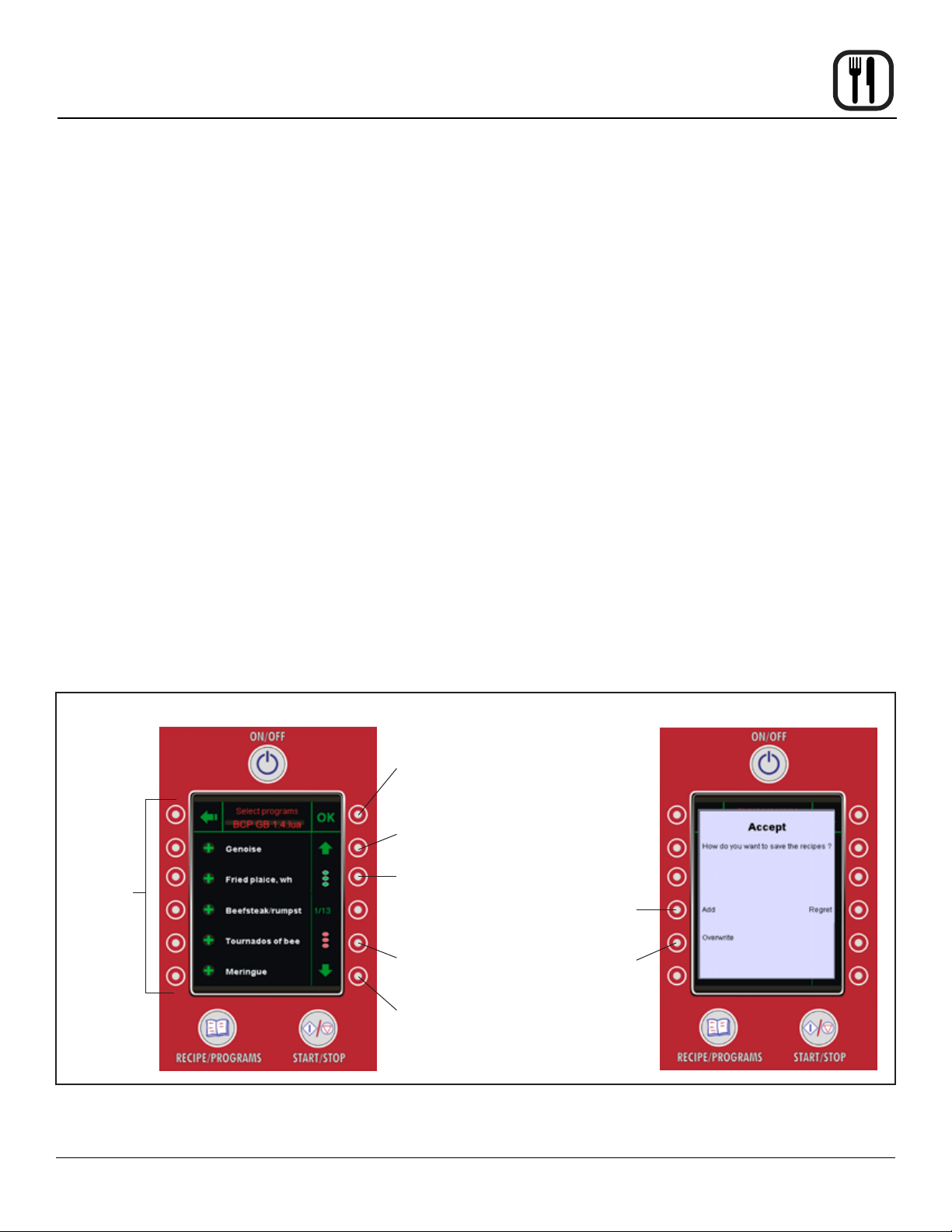
Copy Recipes from USB to Oven
1. Press the key labelled Get Recipes from USB on the
right side of the USB screen.
2. Select the recipes to be copied to the oven.
NOTE: The control displays the product categories
in yellow as folders. Individual program recipes are displayed in white.
3. Press the OK button in the upper right corner of the
display to accept the recipes to be copied.
4. The RECIPE ACCEPT screen is displayed. Press
ADD to add the selected product programs to the
oven. Press OVERWRITE to overwrite existing programs with the recipes on the USB.
Copy Recipes from Oven to USB
1. Press the key labelled Send Recipes to USB on the
right side of the USB screen.
2. Select the location on the USB folder to save the
product recipes. You may overwrite an existing le
or create a new le with a name matching the serial
number of the oven.
3. Press the OK button in the upper right corner of the
display to copy the recipes from the oven to the USB.
Press to
select or
deselect
individual
recipes
Recipe Upload Screen Upload Accept Screen
Press to copy selected
recipes to oven
Press to scroll up
Press to select
all recipes
Press to deselect
all recipes
Press to scroll
down
Press to add
recipes
Press to
overwrite
existing
recipes
Figure 32
43
Page 46

Operation
HACCP Library
The Blodgett BCP/BLCP comes standard with HACCP
data recording. HACCP enables you to control and document production. Data recorded includes production time.
production duration, preparation temperature and core
temperature.
The HACCP library can hold approximately 1000 log les.
You will be notied when the memory is full so that you
can empty the memory with the USB. If nothing is done,
the computer will automatically start to overwrite the old-
est les.
To Activate HACCP Data Recording
NOTE: HACCP data is stored under product recipe
names. Therefore, HACCP is not available for
manual cooking.
HACCP must be activated to record data.
1. Press the MAIN menu key in the upper left corner of
the WORK menu to advance the control to the main
menu.
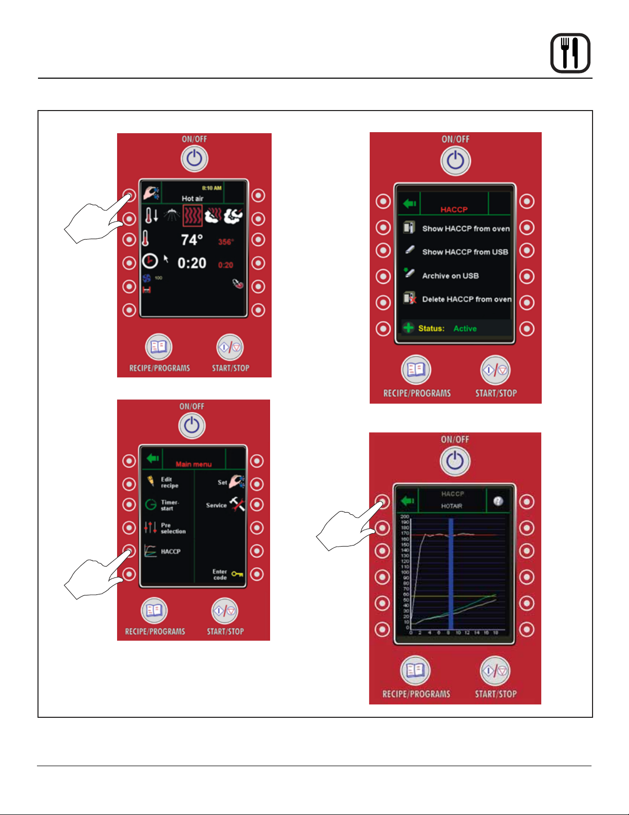
2. Press the HACCP key on the left side of the control to
access the HACCP menu.
3. Be sure that Active appears in the status bar at the
bottom of the control. If the status is inactive, press
the key on the left of the status bar to toggle to Active.
To Backup HACCP Data
1. From the HACCP menu, press the key labelled Archive on USB.
2. The displays reads SAVING HACCP.
3. When the data is saved to the USB the control returns
to the HACCP screen.
NOTE: The HACCP data on the USB can be lo-
cated in the folder with the name of the oven
serial number.
To Delete HACCP Data from the Oven
1. From the HACCP menu, press the key labelled Delete HACCP Data from Oven.
2. The screen will ask you to conrm that you want to
delete all HACCP les. Press the key next to Accept
to delete the les. Press the key next to Regret to
cancel.
3. The control returns to the HACCP screen.
To View HACCP Data
1. From the HACCP menu, press the key labelled either
Show HACCP from Oven or Show HACCP from USB.
2. A list of HACCP log les is displayed. The les are
logged by year, month, date and product name. Use
the UP and DOWN ARROW keys to scroll through the
list until the desired HACCP le is highlighted.
3. Press the OK key in the upper right of the control to
display the HACCP chart.
4. Press the RETURN key at the top left of the screen to
return to the HACCP screen.
44
Page 47
Operation
HACCP Library
Press to move
to MAIN menu
Work Menu
Main Menu
HAACP Menu
Press to access
HACCP Menu
HACCP DATA CHART COLOR KEY:
Red line Preset temp.
White lIne Current oven temp.
Vertical blue line Door opened
Light green line #1 (left) core probe temp.
Light yellow line #2 (right) core probe temp.
HAACP Data Chart
Press to return to
HACCP menu
Figure 33
45
Page 48

Operation
Optional CombiNet
The optional CombiNet feature allows you run the oven
remotely from a pc. This is useful for writing product recipes as well as viewing and downloading HACCP and
other oven data with the convenience of a large screen
and keyboard.
CONNECTING TO A NETWORK OR PC
NOTE: CombiNet requires the installation of Java. The
program can be downloaded from www.java.
com.
1. Remove the control panel cover.
2. Connect the oven to a network or pc via the ethernet
cable. The connection can be found on the bottom of
the control board.
3. Replace the control cover and connect the other end
of the cable to your local network or directly to a pc.
4. Press the MAIN MENU key in the upper left corner to
advance the control to the main menu.
5. Press the OVEN SETUP key on the MAIN menu. The
Oven Setup menu is displayed.
6. Press the NETWORK key on the left of the screen.
The screen displays the IP address of the oven.
NOTE: If the oven is connected to a pc, use the IP
address displayed. If the oven is connected
to a network you may need to change the IP
address to match the naming conguration
for your network
7. Press the OK key on the top right of the control. The
oven will restart itself.
8. From the pc, open a network connections window.
NOTE: Refer to the instructions for your operating
system to locate the window.
Create a network connection using the following settings:
a. Select Local Area Network, right click and select
properties.
b. Select TCPIP version 4. Click on properties.
c. Select “Use the following IP address”.
d. Enter the IP address from your oven control but
change the last 3 digits. They must not match
completely since each connection needs a
unique IP address.
e. Enter the Subnet mask number from the oven
control. This should be an exact match to the
number on the oven control.
f. Click OK to save. Close the network connection
window.
9. From the pc, open an Internet Exporer window and
enter the IP address for the oven in the address bar.
Enter the following login information.
a. Username: superuser
b. Password: 876412
46
Page 49
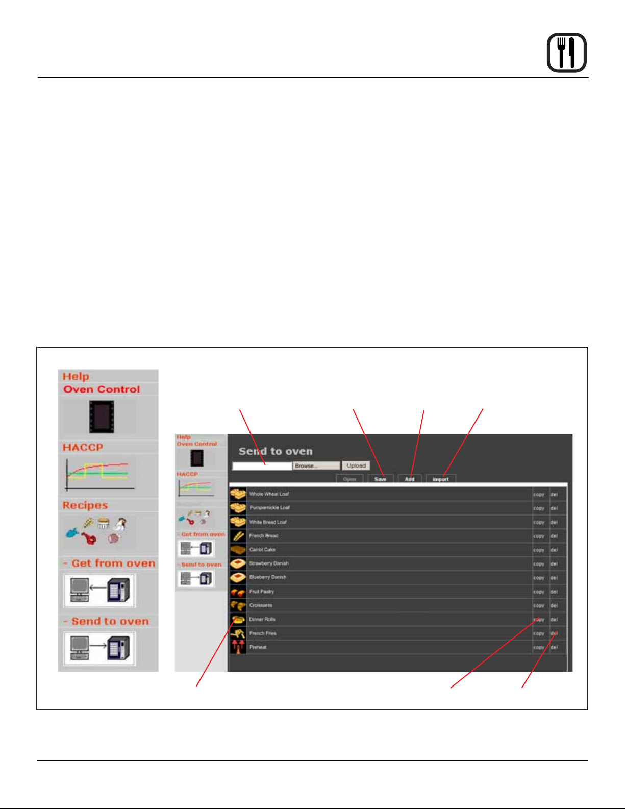
Operation
Optional CombiNet
REMOTE OVEN CONTROL
1. Select Control Oven from the menu on the left of the
screen.
2. The oven display appears in the window on the right.
You are now controlling the oven remotely. You may
use your mouse to navigate through the oven menus
and use your keyboard to enter data.
HACCP VIA COMBI NET
1. Select HACCP from the menu on the left of the screen.
2. The HACCP data is displayed on the right side of the
screen.
Select Function Recipe Screen
Send recipes
to oven
REMOTE RECIPE MANAGMENT
1. Select Recipes from the menu on the left of the
screen.
2. Press Get from Oven to retrieve product recipes currently programmed in the oven library.
3. Add new recipes and/or edit and delete recipes from
the library now located on the pc.
4. Press Send to Oven to download all recipes from the
pc to the oven control. If necessary, click the Browse
button to select the desired recipe location. Click the
Upload button to upload the recipes.
Click to save
recipes on pc
Click to
add recipe
Click to import
additional recipes
Click on category icon
to open recipe
Figure 34
47
Click to copy
recipe
Click to delete
recipe
Page 50

Maintenance
Cleaning & Preventative Maintenance
DAILY CLEANING
Daily cleaning of your Combi oven is essential for sanita-
tion, and to ensure against operational difculties.
Cleaning the Exterior
1. The exterior of the appliance may be cleaned and
kept in good condition with a light oil. Saturate a cloth
and wipe the appliance when it is cold; wipe dry with
a clean cloth.
WARNING!!
DO NOT spray the outside of the appliance
with water or clean with a water jet. Cleaning
with a water jet can impregnate chlorides into
the stainless steel, causing the onset of corrosion.
Cleaning the Interior
NOTE: DO NOT use corrosive cleaners not intended for
oven cleaning on your Combi oven.
Blodgett recommends the following products for cleaning
and rinsing of your Blodgett Combi oven. If you choose
to use products other than what Blodgett recommends,
please have your suppler send us the MSDS sheet on the
proposed alternate so we can ensure it meets our standards. Non approved products can cause harm to your
unit and can potentially void your warranty.
Recommended oven cleaners:
Johnson Diversey Suma Nova L-6
• Four, 1 gallon (3.78 litre) containers
Product code 57252280
Run the CombiWash automatic cleaning cycle as follows:
1. Check that the oven cleaner and rinse agent containers are both full.
2. From the WORK menu, select the clean cycle. The
CombiWash menu is displayed.
3. CombiWash features four different cleaning cycles.
Use the Left and Right Arrow keys to select the desired cleaning cycle.
Step 1 (44 minutes)
Step 2 (1 hour)
Step 3 (1 hour, 49 minutes)
Step 4 (2 hours, 38 minutes)
NOTE: Use Steps 1 or 2 after steaming and roast-
ing at low temperatures. Use Steps 3 or 4
after steaming and roasting at high temperatures.
4. Press the Start/Stop key to initiate the clean cycle.
5. If the cavity temperature is above 175ºF (80ºC), the
oven will automatically enter cool down. When the
cavity is below 175ºF (80ºC) the CombiWash cycle
begins.
6. The control counts down the time remaining in the
wash cycle.
7. When the wash cycle is over, the oven automatically
switches to an energy saving standby mode.
• One, 5 gallon (18.9 litre) container
Product code 57252100
Recommended Rinse Aid:
Johnson Diversey Suma Maro A8.8
• Four, 1 gallon (3.78 litre) containers
Product code 57270280
• One, 5 gallon (18.9 litre) container
Product code 57270100
1. Open the oven door.
2. Use the attached spray hose, located beneath the
control, to clean the front drip tray. Water will run to
the drain in the oven cavity.
48
Page 51
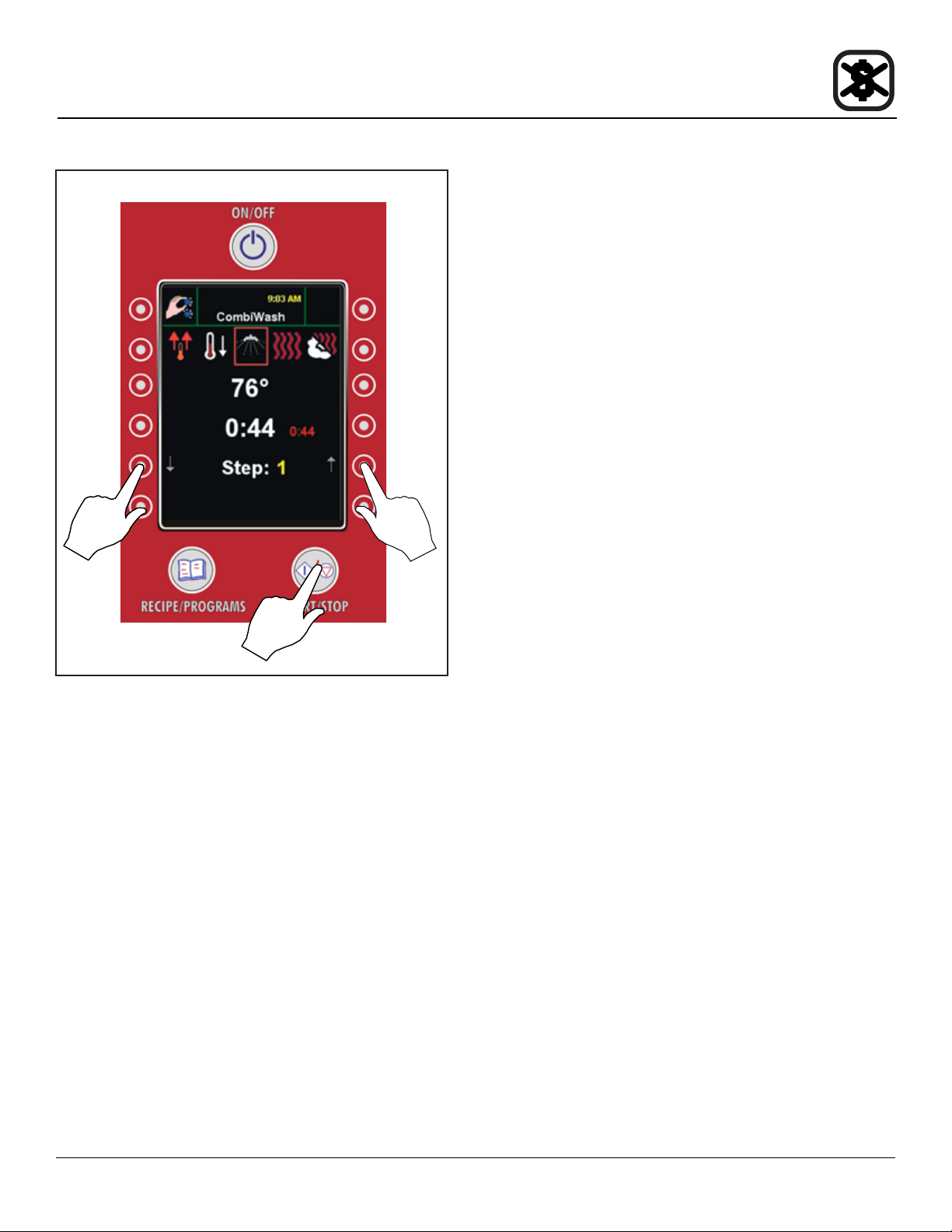
Maintenance
Cleaning & Preventative Maintenance
Press to
select
cleaning
mode
CombiWash Menu
Press to start
CombiWash
Figure 35
Press to
select
cleaning
mode
WEEKLY CLEANING
In addition to the daily cleaning, it is necessasry to clean
the control lter and behind the fan guard on a weekly basis. This is necessary for proper functioning of the oven.
Scale will build up on the fan and heat source leading to
a less efcient oven.
Cleaning the Control Filter
The control lter is located below the control compartment, in front of the spray hose.
1. To remove, pull down on the black knob on the left of
the lter.
2. Clean the lter with soap and water.
3. Reinstall the lter. Press up on the lter until the back
of the knob is inserted into the hole in the bottom of
the oven.
4. Push up on the center of the knob to expand the back
of the knob securing the lter.
Cleaning Behind the Fan Guard
1. Loosen the two screws and on the fan guard (or baf-
e).
2. Swing the bafe forward.
3. Thoroughly spray cleaner onto the fan and heat
source. Place the oven in the steam mode for approximately 10 minutes.
4. After ten minutes, rinse the cleaner off. Return the fan
guard to the closed position. Rotate the two screws to
secure the fan guard.
PREVENTIVE MAINTENANCE
The best preventive maintenance measures are the
proper initial installation of the equipment and a
program for cleaning the appliance routinely. The Oven/
Steamer requires no lubrication. Contact the factory, the
factory representative or a local Blodgett Combi service
company to perform maintenance and repairs should they
be required.
49
Page 52

Maintenance
Deliming - BCP only
The control keeps track of boiler usage between deliming.
When the oven has reached 95% of the time the control
warns the operator that the oven needs to be delimed.
This is a warning only, the oven can be used all day before deliming.
Deliming the Oven
1. Be sure the container delivering the deliming agent
to the appliance is full. Be sure to use a non-diluted
deliming agent.
2. From the MAIN Menu, select the SERVICE key.
3. The control displays the SERVICE menu. Press the
Work Menu
DELIME DIAGNOSIS key on the right of the control.
4. The control displays the Delime Diagnosis screen.
Press the START DELIMING key on the right side of
the control.
5. The remainder of the process is automatic. The control displays the deliming steps as they occur.
NOTE: The oven can be delimed at any time.
Main Menu
Press to go
to SERVICE
Menu
Press to go to
MAIN Menu
Service Menu
Press to enter
DELIME Menu
Delime Diagnosis Screen
Press to start
deliming
process
Figure 36
50
 Loading...