

Page 1
COMBI
BCX
COMBINATION OVEN STEAMER
TROUBLESHOOTING MANUAL
14G AND BX14G
BLODGETT COMBI
www.blodgett.com
44 Lakeside Avenue, Burlington, Vermont 05402 USA ~ Tel. (802) 658-6600 Fax (802) 652-2814
PN
52051 Rev B (12/15/2010)
Page 2

TABLE OF CONTENTS
Section 1 Controls
Manual Control Operation………………………………………………………………1-3
Manual Control Second Level Programming……………………………………………..4
New Manual Control Operation………………………………………………………...5-7
New Manual Control Second Level Programming……………………………………..8-9
New Manual Control Factory Level Programming…………………………………..10-11
MenuSelect Control Operation……………………………………………………….12-15
MenuSelect Control Second Level Programming……………………………………16-17
Notes……………………………………………………………………………………..18
Section 2 Troubleshooting
Troubleshooting Guide……………………………………………………………….19-22
Incoming Power Supply………………………………………………………………….23
Logic Board Dcv Test Points…………………………………………………………….24
Cool Down Flow Chart…………………………………………………………………..25
Hot Air Operation Flow Chart…………………………………………………………...26
Steam Operation Flow Chart…………………………………………………………….27
Combi Mode Operation Flow Chart……………………………………………………..28
Door Switch Troubleshooting Flow Chart……………………………………………….29
Float Switch Troubleshooting Flow Chart……………………………………………….30
Convection Motor Direction Flow Chart………………………………………………...31
Drain Valve Troubleshooting Flow Chart……………………………………………….32
Logic Board LED Designations Flow Chart…………………………………………33-34
IFB (LED) Designations Flow Chart…………………………………………………….35
Point to Point Troubleshooting……………………………………………………….36-38
Symbol Designations…………………………………………………………………….39
Notes……………………………………………………………………………………..40
Section 3 Motor Speed Inverter Troubleshooting
Manual Control Inverter Programming………………………………………………41-42
MenuSelect Control Inverter Programming.................................................................43-44
Inverter Fault Codes and Stored Fault Codes…………………………………………...45
Section 4 Wire Schematic & Wire Harness
Manual Control Schematic W/Float P/n 39680………………………………………….47
Manual Control Schematic W/Level Board P/n 52853………………………………….48
New Manual Control Schematic 120V P/n 53849……………………………………….49
New Manual Control Schematic 208V – 240V P/n 53850………………………………50
MenuSelect Control Schematic W/Float P/n 51228……………………………………..51
MenuSelect Control Schematic W/Spritzer P/n 52855…………………………………..52
MenuSelect Control Schematic 480V P/n 53852………………………………………..53
BX14G Manual Control Schematic P/n 50546…………………………………………..54
BX14G MenuSelect Control Schematic P/n 51155……………………………………...55
Page 3

Section 5 Error Codes
Manual Control W/Meat Probe Error Codes…………………………………………….56
New Manual Control W/Meat Probe Error Codes……………………………………….57
MenuSelect Control Error Codes………………………………………………………...58
Probe Chart
BCX14G with Manual Control
Part number 39800 located at the rear of the oven cavity below the blower motor a two
wire probe 1K value. At 75° 1090 ohm’s and at 300° 1575 ohm’s
BCX14G with MenuSelect Control
Part number 50310 located at the rear of the oven cavity below the blower motor a two
wire probe right angle 1K value. At 75° 1090 and at 300° 1575 ohm’s
(BX14G) with MenuSelect Control
Part number 50310
(BX14G/BCX14G with the New Manual)
Part number 50310 all the same as the above for MenuSelect Controls.
(BX14G) with Manual Control
Part number 50636 located at the rear of the oven cavity below the blower motor a 4 wire
probe 1K value. At 75° 1090 ohm’s and at 300° 1575 ohm’s
all the same as above for the BCX14G with MenuSelect Control.
Meat Probes
All Controls use the same Meat probes
Part number 39797 a 6” removable probe the plugs into the blue meat probe jack at the
bottom of the control panel.
This is a 1K probe at 75° 1090 ohm’s and at 300° 1575 ohm’
Page 4
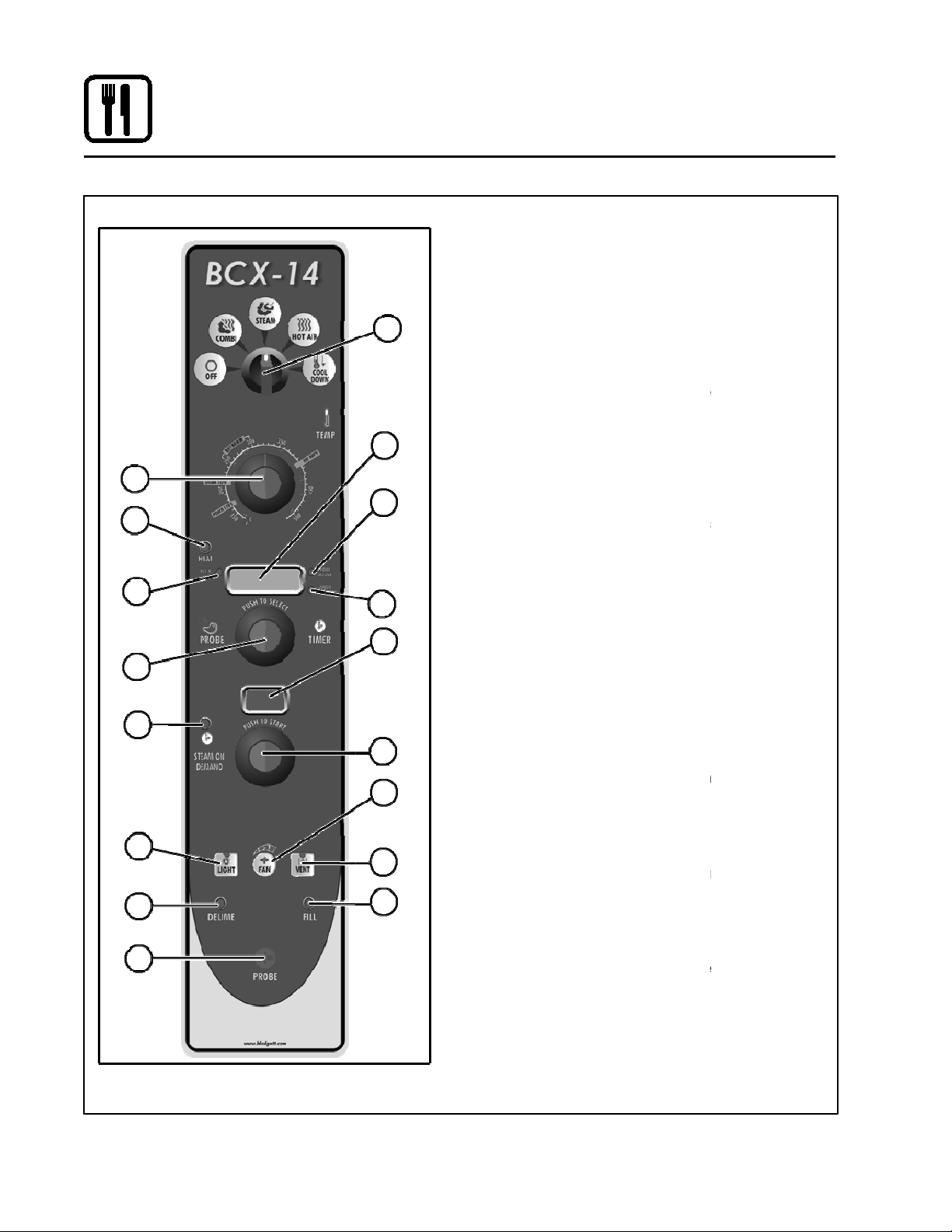
Standard Controls for Models BCX 14 and BX 14
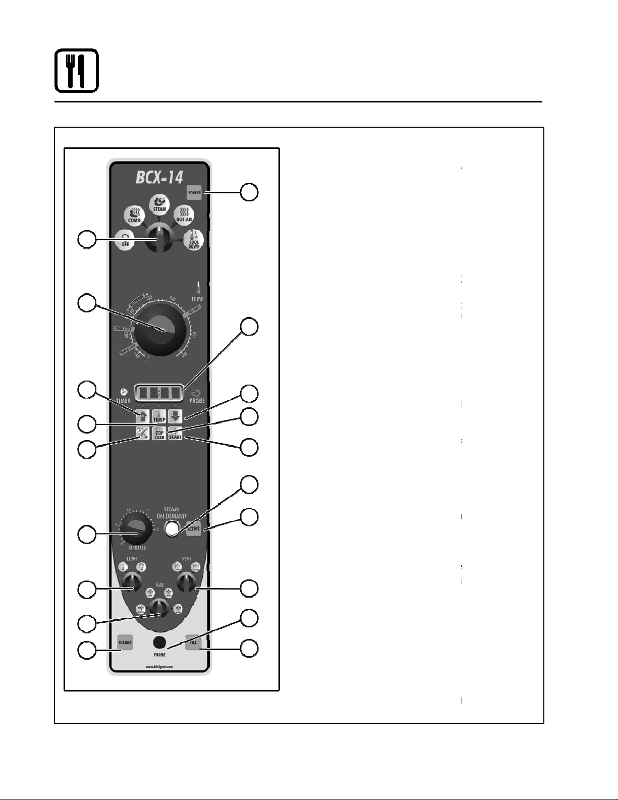
1
when lit indicates
power to the unit is turned on.
-
the oven on or off. Allows selection of
Steam, Hot Air, Combi or Cool Down Modes.
desired cooking temperature.
displays time and temperature
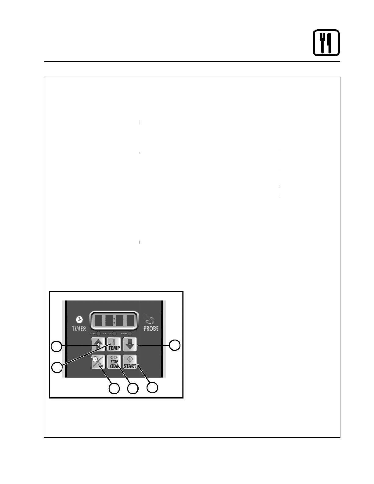
UP & DOWN ARROW KEYS
enter values in the display.
press to display the ac
tual probe temperature during core cooking or
actual cavity temperature in timer mode.
TIME/PROBE TOGGLE KEY
select either timer or probe cooking.
use to clear or stop
the timer and silence the buzzer.
press to start the timer.
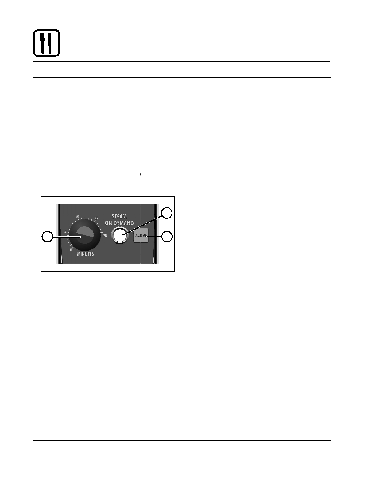
STEAM ON DEMAND TIMER
duration for steam on demand.
STEAM ON DEMAND SWITCH
ini tiate steam injection cycle.
STEAM ON DEMAND LAMP
steam on demand is activated.
used to turn the lights
used to open or
close vent to release steam fr
used to select fan
used to connect
the core temperature probe to the control.
illuminated until the steam
gen erator is filled with water.
NOTE: Model BX 14 ovens do not have a
DELIME LAMP (BCX 14 ovens only)
Flashes when steam generator deliming
is needed. Remains steady when deliming
CLEAN LAMP (BX 14 ovens only)
when the unit has been in use for a prepro
grammed time and needs to b
Operation
CONTROLS IDENTIFICATION
1. POWER ON LAMP -
2. MODE SELECTOR SWITCH
turns power to
2
3. TEMPERATURE DIAL -
used to set
4. DISPLAY in formation.
5.
3
4
6. ACTUAL TEMP KEY -
7.
- press to
- used to
8. CLEAR/STOP KEY -
5
5
9. START KEY -
10.
8
6
7
9
11.
12.
11
13. LIGHTS SWITCH on and off.
- used to set
- used to
- lights when
14. CAVITY VENT SWITCH -
10
12
15. FAN SPEED SWITCH speed.
om cavity.
16. PROBE CONNECTION -
13
14
17. FILL LAMP -
16
17
15
18
1
fill lamp.
18.
pro cess is active.
-
- Flashes
e cleaned.
Page 5
Press the TIMER/PROBE TOGGLE KEY (7)
to select the timer mode. The TIMER LED
Turn the MODE SELECTOR Switch (2) to
Set the TEMPERATURE DIAL (3) to the de
emperature no
C).
For poaching, turn the temperature dial to
F (82
The optimum temperature for Combi
F (149 177
When the oven has reached the cook
, load the product.
Use the ARROW KEYS (5) to enter the desired
cook time in the display. You can clear the dis
play by pressing the CLEAR/STOP KEY (8).
Press the START KEY (9) to begin the timer.
The temperature, time and mode can be al
at any time during the cooking process.
To stop the timer, press the CLEAR/STOP KEY
When the timer reaches 00:00, the buzzer
sounds. Press the CLEAR/STOP KEY (8) to
si lence the buzzer. Remove the product.
8
Operation
Standard Controls for Models BCX 14 and BX 14
5
Press the TIMER/PROBE key (7) to select
the probe mode. The PROBE LED below
Use the ARROW KEYS (5) to enter the
desired final cook temperature in the
display. You can clear the display by
pressing the CLEAR/ STOP KEY (8).
Insert the core probe into the product. Load
product into the oven and close the door. Be
sure that the terminal end of the core probe is
outside of the oven and clear of the door.
Connect the core probe to the PROBE CON
NECTION (16) at the bottom of the
The display gives the actual core probe
When the product reaches the final cook
tem perature the buzzer sounds.
NOTE: The unit can be cooled down rapidly
for steaming, cleaning, etc.
To cool down the oven cavity, open the
door and select Cool Down on the MODE
SELEC TOR Switch (2).
TIMER COOKING
1.
PROBE COOKING
1.
below the display lights.
2.
the desired function.
3.
sired cook temperature.
For Steam mode, set the t
high er than 212_F (100_
the POACH position, 180_
mode is 300 350_
4.
temper ature
5.
6.
tered
(8).
7.
emperature no
_C).
_C).
2.
3.
4.
5.
6.
COOL DOWN
1.
the dis play lights.
control.
tem perature.
5
6
7
9
2
Page 6
Standard Controls for Models BCX 14 and BX 14
STEAM ON DEMAND
How to set the Steam On Demand feature:
While in the Hot Air or Combi mode, the unit can
be set to steam for a
timed period. At the end of the
timed cycle the unit reverts back to the original set
ting. Steam On Demand can be used at any time
during the cook cycle.
is not available
1. Set the desired •steam
on" time with
STEAM ON DEMAND TIMER (10).
2. Press the STEAM
ON DEMAND SWITCH (11).
The STEAM ON DEMAND LAMP (12) lights.
Uses for Steam On
Demand:
Most of the ideas came from our creative custom
ers. Experiment with this feature on your own and
let us know of any new uses.
Add a minute or two at the beginning when bak
D
ing bread for a shiny crust.
Kick start large loads such as 20 or more chick
in
ens. By starting large loads with 5 to 8 minutes
of steam you help the oven recover and cut the
cooking time by
more than 10%.
the
Bake bagels without boiling. By starting raw ba
gels with 1 to 2 minutes of steam you can
achieve a beautiful crust.
F to 250
Combi mode using 2 minutes of on demand
steam.
cooking chicken wings, try setting the
oven in the Combi mode at 375
minutes of Steam On Demand. This method will
stop the tips from burning. Total cooking time is
approximately 12
minutes.
Pork ribs tend to pull off the bone better when
using 5 to 8 minutes of Steam On Demand. Try
ribs in the Combi mode at 350
F and use 3
_
F.
Operation
NOTE: Steam On Demand
steam mode.
10
D
D
D
D
D
11
12
Cream caramel is great at 230
When
_
_
F in the
_
3
Page 7

Standard Control Second Level Programming
3. Press and Hold
for 5 seconds and release
or
Combi Manual Control Temp. (BP# 39673)
Instructions For +7° Temperature Offset
Recommended: Read instructions before programming. If each step is not
conducted within 9 seconds, the control will lock up and the programming
sequence will have to be restarted from step 1
1. Power oven off
. Power on oven in Combi Mode
2
4. Press and hold
5. Toggle
6. Press and release
7. Toggle
8. Press and release
9. Press
until "2 X X X" is displayed. Where "X X X" are any number
until Screen displays "P 3 X X" where "X X" are any number
for 5 seconds and release
PROBE LED will begin to Flash
until Screed displays "P 2 0 7"
TIMER LED will begin to flash
10. Press and release PROBE LED will begin to flash
11. Toggle or until Screed displays "P 3 0 0"
12. Do not touch oven for 10 seconds. "0 0 0" will appear. Temp. offset is now programmed
13. Turn off oven and turn back on
4
Page 8
Standard Controls for Models BCX 14 and BX 14
1
14
-
the oven on or off. Allows selection of
Steam, Hot Air, Combi or Cool Down Modes.
displays time and temperature
desired cooking temperature.
lights when the oven is
lights when the cook time is
lights when the
actu al probe temperature is displayed
lights when the
core setpoint temperature is displa
use to select and
set either cook time or probe temperature
STEAM ON DEMAND DISPLAY
STEAM ON DEMAND LAMP
steam on demand is activated.
STEAM ON DEMAND KNOB
duration for steam on demand
press to turn the oven
used to select fan speed.
used to open or
close vent to release steam from cavity.
DELIME LAMP (BCX 14 ovens only)
Flashes when steam generator deliming
is needed. Remains steady when deliming
illuminated until the steam
gen erator is filled with water.
NOTE: Model BX 14 ovens do not have a
used to connect
the core temperature probe to the control.
Operation
3
4
5
8
10
2
7
11
13
6
9
CONTROLS IDENTIFICATION
1. MODE SELECTOR SWITCH
2. DISPLAY in formation.
3. TEMPERATURE DIAL -
4. HEAT LAMP calling for heat
5. TIMER LED displayed
6. PROBE ACTUAL LED -
7. PROBE SETPOINT LED -
8. TIMER/PROBE KNOB -
9.
the steam on demand time
10.
11.
12. LIGHTS KEY lights on and off
13. FAN SPEED KEY -
14. CAVITY VENT KEY -
15.
turns power to
used to set
yed
- displays
- lights when
- use to set
-
12
15
17
16
5
pro cess is active.
16. FILL LAMP -
17. PROBE CONNECTION -
fill lamp.
Page 9

Press the TIMER/PROBE KNOB (8) to select
the timer mode. The TIMER LED lights.
Turn the MODE SELECTOR Switch (1) to
Set the TEMPERATURE DIAL (3) to the de
For Steam mode, set the temperature no
C).
For poaching, turn the temperature dial to
F (82
The optimum temperature for Combi
F (149 177
When the oven has reached the cook
temper ature, load the product.
Rotate knob to enter the desired cook
time in the display. You can clear the
display by rotat ing counter clockwise.
The timer begins on its own.
The temperature, time and mode can be al
tered at any time during the cooking process.
When the timer reaches 00:00, the buzzer
sounds. Press or rotate the TIMER/PROBE
KNOB (8) counter clockwise to silence the
buzzer. Remove the product.
Operation
Standard Controls for Models BCX 14 and BX 14
Press the TIMER/PROBE knob (8) to
select the probe setpoint mode. The
LED (7) lights.
Rotate the knob to enter the desired final
cook temperature in the display.
Insert the core probe into the product. Load
product into the oven and close the door. Be
sure that the terminal end of the core probe is
outside of the oven and clear of the door.
Connect the core probe to the PROBE CON
NECTION (17) at the bottom of the
The display gives the actual core probe tem
perature by pressing the TIMER/PROBE knob
When the product reaches the final cook
tem perature the buzzer sounds.
NOTE: The unit can be cooled down rapidly
cleaning, etc.
To cool down the oven cavity, open the
door and select Cool Down on the MODE
SELEC TOR Switch (1).
TIMER COOKING
1.
2.
the desired function.
3.
sired cook temperature.
PROBE COOKING
1.
PROBE SET POINT
2.
3.
high er than 212_F (100_
the POACH position, 180_
mode is 300 350_
4.
5.
6.
7.
_C).
_C).
4.
5.
(8) again.
6.
control.
COOL DOWN
1.
for steaming,
6
Page 10

Standard Controls for Models BCX 14 and BX 14
How to set the Steam On Demand feature:
While in the Hot Air or Combi mode, the unit
can be set to steam for a timed period. At the
end of the timed cycle the unit reverts back to
Demand can
be used at any time during the cook cycle.
NOTE: Steam On Demand is not available in
Turn the STEAM ON DEMAND KNOB (11) to
set the desired length of time. The time is dis
played in the STEAM ON DEMAND DISPLAY
Press the STEAM ON DEMAND KNOB (11).
The STEAM ON DEMAND LAMP (10) lights.
Most of the ideas came from our creative
custom ers. Experiment with this feature on
your own and let us know of any new uses.
Add a minute or two at the beginning when
bak ing bread for a shiny crust.
Kick start large loads such as 20 or more
chick ens. By starting large loads with 5 to 8
minutes of steam you help the oven recover
and cut the cooking time by more than 10%.
ke bagels without boiling. By starting
raw ba gels with 1 to 2 minutes of steam
you can achieve a beautiful crust.
F to 250
Combi mode using 2 minutes of on demand
When cooking chicken wings, try setting
oven in the Combi mode at 375
minutes of Steam On Demand. This method
will stop the tips from burning. Total cooking
time is approximately 12 minutes.
Pork ribs tend to pull off the bone better when
using 5 to 8 minutes of Steam On
Try ribs in the Combi mode at 350
Operation
STEAM ON DEMAND
the original set ting. Steam On
Uses for Steam On Demand:
D
D
1.
2.
steam mode.
(9).
D Ba
D Cream caramel is great at 230_
steam.
D
D
_F in the
_F and use 3
Demand.
_F.
the
7
Page 11
Se
rvice
Level Programming
BCX, BX – NEW MANUAL CONTROL
Code: 7378
(The oven needs to be in the “OFF” position)
Press the Timer Dial Till “0000” Is Displayed
Turn the Dial: Scroll the flashing # to (7)000
Press the Dial to Enter Scroll the flashing # to 7(3)00
Press the Dial to Enter Scroll the flashing # to 73(7)0
Press the Dial to Enter Scroll the flashing # to 737(8)
Press the Dial to Enter Scroll to (DIAG) Diagnostics
Press the Dial to Enter
“D-01” Is Displayed
(Cavity Heat Relay)
Press the Dial to Enter Turn Dial CW to “ON”
Turn Dial CCW to “OFF”
Press the Dial to EXIT
(CONTINUE) (FOLLOW STEPS ABOVE)
Scroll the Dial to D-02 Boiler Heat Relay
D-03 Water High Level Switch Status
D-04 Water Low Level Switch Status
D-05 Drain Relay
D-06 Fill Relay
D-07 Steam Relay
D-08 Quench Relay
D-09 Motor-Reversals Relay Gently
D-10 Motor Gently
D-11 Motor Low
D-12 Motor High
D-13 Motor Turbo
D-14 Door Status
D-15 Lights Relay
D-16 Delime Pump Relay
D-17 Software Flash Number
D-18 Software Number
D-19 Software Download Number
Page 8
Page 12

Se
rvice
Level Programming
BCX, BX NEW MANUAL CONTROL
Code: 7378
(The oven needs to be in the “OFF” position)
D-20 SIB Software Number
D-21 Cavity Set Temperature
D-22 Cavity ACT Temperature
D-23 Cooling Fan Probe Temperature
D-24 Quench Probe Temperature
D-25 Core Probe Temperature
D-26 Boiler Tank Temperature
D-27 Main Switch
D-28 Fan Feedback Input
D-29 Cook Done relay
D-30 Vent relay
D-33 Cool Fan Relay
D-34 Hot Air relay
D-35 Hot Air Enable Relay
D-37 All Relays
D-38 Display and LED Test
END End Of Diagnostic Test
Press Dial to Exit
Page 9
Page 13
Factory
Level Programming
BCX, BX – NEW MANUAL CONTROL
Code: 3228
(The oven needs to be in the “OFF” position)
Press the Timer Dial Till “0000” Is Displayed
Turn the Dial: Scroll the flashing # to (3)000
Press the Dial to Enter Scroll the flashing # to 3(2)00
Press the Dial to Enter Scroll the flashing # to 32(2)0
Press the Dial to Enter Scroll the flashing # to 322(8)
Press the Dial to Enter “P-01” Is Displayed
Press the Dial to View Turn Dial to: (F)
Press the Dial to Retune Turn Dial to: P-02
(CONTINUE) (FOLLOW STEPS ABOVE)
P-## “ Set To “
(P-02) Cool Down Temp 100F
(P-03) Ready Beep ON
(P-04) Fan Reverse Time 6:00
(P-05) Cook Done Beeper Yes
(P-06) Delime Interval 30 Hours
(P-07) Flush Interval 24 Hours
(P-08) Appliance Type Gas
(P-09) Machine Type BCX / BX
(P-10) Max Steam On Demand
20
(P-11) Min Hot Air Set Point 140F
(P-12) Max Hot Air Set Point 500
(P-13) Min Steam Set Point 85F
(P-14) Max Steam Set Point 225F
(P-15) Max Core Probe Pull Temp 200F
(P-16) Upper Hot Air Hysteresis 1F
(P-17) Lower Hot Air Hysteresis 1F
(P-18) Upper Steam Hysteresis 1F
(P-19) Lower Steam Hysteresis 1F
Page 10
Page 14

Factory
Level Programming
BCX, BX NEW MANUAL CONTROL
Code: 3228
(The oven needs to be in the “OFF” position)
(P-20) Upper Ready Band 25F
(P-21) Lower Ready Band 10F
(P-22) Cavity Probe Offset 0F
(P-23) Core Probe Offset -2F
(P-24) Spritzer Solenoid Duty Cycle
(P-25) User Response Timeout
33
5
(P-26) Sleep Mode Timeout 1
(P-27) Counter Start Delay 2
(P-28) Quench Probe Yes
(P-29) SCK Address 30
(P-31) ACT Oven Temp Display
No
(P-32) Remote Beeper Yes
Press Dial to Exit Scroll to END
Press Dial to Exit End Of Factory Programming
Page 11
Page 15
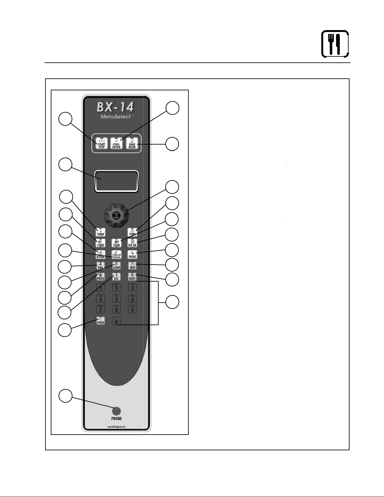
MenuSelect Control for Models BCX 14 and BX 14
11
Operation
START/STOP KEY press to start, cancel or
pause the bake
COOL DOWN KEY initiates oven cool down
cycle
BAKE MORE KEY press at the end of a bake
cycle to add additional bake time in one min
ute increments.
DISPLAY displays time or temperature and
other information related to oven function and/
or programming.
DIAL used to enter set points, time, and pro
grammable settings. Also used to select the
programmed product.
TEMP KEY used to set or change the bake
7
temperature
TIME KEY used to set or change the bake
time.
COMBI KEY press to enter combi mode
STEAM KEY press to enter steam mode
HOT AIR KEY press to enter hot air mode
RETHERM KEY press to enter retherm
mode, this mode uses steam to reheat frozen
or precooked product. Retherm has a temper
19
ature limit of 250 300
_
F.
STEAM ON DEMAND KEY used to initiate
steam injection cycle
20
13. PROBE KEY press to use core probe cooking
FAN KEY press to select the fan speed
LIGHT KEY press to turn the lights on and off.
VENT KEY press to manually open and close
the oven vent
PROGRAM KEY press to enter product pro
gramming and save programmed settings.
ESCAPE KEY press to back up one step dur
ing programming
MAINTENANCE KEY press to enter manager
programming and save programmed settings
ALPHA/NUMERIC KEYPAD used to program
recipes.
POWER KEY used to place control in and out
of standby mode.
CORE PROBE CONNECTION plug core tem
perature probe in here when using probe
cooking
18
1
4
12
14
15
17
21
22
6
8
2
3.
3
4.
5.
5
9
10
13
16
14.
15.
17.
18.
20.
21.
CONTROL DESCRIPTION
1.
2.
6.
7.
8.
9.
10.
11.
12.
16.
19.
22.
12
Page 16

MenuSelect Control for Models BCX 14 and BX 14
Be sure the gas shutoff switch and/or circuit
breaker switch below the control panel are
in the on position. The display flashes OFF
PRESS POWER KEY TO START.
NOTE: If the real time clock and auto wake
up functions are enabled the
display reads PRESS POW
TO START AUTO START.
Press the POWER KEY (21). The display
reads PREHEAT and the oven heats to the
last manu al set temperature in the hot air
mode. The dis play flashes READY / IDLE
and the alarm beeps 5 times when the
eady to bake.
1. Turn the DIAL (5) until the display reads
Press the TIME KEY (7). Rotate the dial, or
use the alpha/numeric keypad to enter the
desired bake time. Press the center of the
NOTE: Time is set in one minute increments
using the dial. To set time in less
than one minute increments use the
Press the TEMP KEY (6). Rotate the dial, or
use the alpha/numeric keypad to enter the
de sired bake temperature. Press
of the dial to set the bake temperature. The
oven preheats to the new temperature.
NOTE: Temperature is set in 5 degree incre
ments using the dial. To set time in
less than 5 degree increments use
the al pha/numeric keypad.
Press the desired mode key, combi,
If Combi or Retherm are selected, rotate
the dial, or use the alpha/numeric keypad
to enter the desired percentage of steam.
NOTE: Retherm has a temperature limit of
When the display flashes READY / IDLE,
open the doors. Load the product.
Press the START/STOP KEY (1) to begin the
bake cycle. The timer counts down and the
display alternates between the cooking
mode and the name of the product.
Turn the DIAL (1) until the name of the
product is highlighted. Press the center of
the dial to select. The oven preheats to the
programmed temperature in the correct
cooking mode. The display flashes READY /
IDLE and the alarm beeps 5 times when the
is at tempera ture and ready to bake.
Open the doors. Load the product.
Press the START/STOP KEY (1) to begin the
bake cycle. The timer counts down and the
display alternates between the cooking
mode and the name of the product.
Press the PROBE key (13) to select the
probe mode. The display reads CORE
PROBE COOK & HOLD. Turn the dial to
select either YES or NO. Press the center
If YES is selected, Cook & Hold has been
Hold mode, the
oven cav ity lowers to the product pull
temperature as the product cooks.
If NO is selected, Cook & Hold has not
been enabled the cavity maintains the
Turn the DIAL to enter the desired product pull
temperature in the display. Press the center of
the dial to save the pull temperature.
Press the TEMP KEY (6). Rotate the dial, or
use the alpha/numeric keypad to enter the
de sired bake temperature. Press
of the dial to set the bake temperature. The
oven preheats to the new temperature.
NOTE: Temperature is set in 5 degree incre
ments using the dial. To set time in
less than 5 degree increments use
the al pha/numeric keypad.
Operation
OVEN STARTUP
1.
2.
ER KEY
6.
PROGRAMMED COOKING
1.
oven is at temperature and r
MANUAL COOKING
MANUAL.
2.
dial to set the bake time.
3.
alpha/ numeric keypad.
4.
steam, hot air or retherm.
the center
oven
2.
3.
PROBE COOKING
1.
of the dial to se lect.
en abled. In the Cook &
cook temper ature.
2.
3.
the center
5.
250 300_F.
13
Page 17

MenuSelect Control for Models BCX 14 and BX 14
Press the desired mode key, combi,
are selected, rotate
the dial, or use the alpha/numeric keypad
to enter the desired percentage of steam.
NOTE: Retherm has a temperature limit of
Insert the core probe into the product. Load
product into the oven and close the door. Be
sure that the terminal end of the core probe is
outside of the oven and clear of the door.
Connect the core probe to the PROBE CON
NECTION (22) at the bottom of the
NOTE: Do not connected the probe before
the cook mode has been selected.
The display gives the actual core probe tem
perature as well as the oven set temperature.
When the product reaches the pull
tempera ture the buzzer sounds.
Press the START/STOP KEY (1) to silence
The cavity tempera
ture continues to drop to the product pull
tem perature and the display counts up,
telling the operator long the product has
been held. Dis connect the core pro
and remove the prod uct when ready.
If not using Cook & Hold
mains at the cook temperature. The
display does not count up. Disconnect the
core probe and remove the product when
While in the Hot Air, Combi or retherm modes,
the unit can be set to steam for a timed period
of up to 20 minutes. At the end of the timed
cycle the unit reverts back to the original
setting. Steam On De mand can be used at
k cycle.
Press the STEAM ON DEMAND KEY (12).
Rotate the dial, or use the alpha/numeric key
pad to enter the desired steam on demand
Operation
time. Press the center of the dial to
initiate Steam on Demand cycle.
NOTE: Steam on Demand time is set in one
minute increments using the dial. To
set time in less than one minute incre
ments use the alpha/numeric keypad.
The Steam on Demand LED flashes until
the steam time has expired.
Venting Moisture from the Oven Cav
Press the VENT KEY (16). This manually
opens the vent until the key is pressed
To pause a cook cycle, press the START/
STOP KEY (1). The LED on the start/stop
key flashes. The bake cycle will pause
until the key is pressed again.
To cancel the cook cycle, press and hold
the START/STOP KEY (1).
ANY COOK CYCLE
An alarm sounds, the display reads DONE.
If more bake time is desired, press the BAKE
MORE KEY (3). This will add an additional one
minute of time for each press of the key.
When you are satisfied with the bake, press
(1) to silence the alarm.
Open the door to remove the product.
Press the COOL DOWN KEY (2). The
display reads AUTO COOL DOWN
ACTUAL TEMP. To speed up the cool
down process, open the doors and press
the VENT KEY (16) to open the vent.
When the oven has cooled down, the display
reads OFF PRESS POWER KEY TO START.
NOTE: The lights shut off and the vent
closes automatically at the end of
the cool down cycle.
4.
steam, hot air or retherm.
If Combi or Retherm
5.
6.
250 300_F.
7.
8.
9.
the buzzer.
If using Cook & Hold -
the buzzer sounds.
DURING ANY COOK CYCLE
Steam On Demand
control.
be
- The cavity re
3.
1.
again to close it.
Pause a Bake Cycle
1.
Cancel a Cook Cycle
1.
AT THE END OF
1.
2.
3.
the START/STOP KEY
OVEN SHUTDOWN
1.
2.
ity
any time during the coo
1.
2.
14
Page 18

Control for Models BCX 14 and BX 14
Press the PROGRAM KEY (17). If the control
is password protected, the display reads EN
TER CODE. Use the alpha/numeric keypad
passcode 3124, then
press the center of the dial to enter the
NOTE: Use the following procedure to name a
new product or edit the name of an
For a new recipe, turn the dial to the first open
product. Press the center of the dial to select.
To edit an existing name, rotate the dial to
the name to be changed. Press the center
Use the dial to scroll down to Edit Name.
ess the center of the dial to enter the
Turn the dial or use the alpha/numeric keypad
to select the first character. Press the center of
the dial to advance to the next character. Re
NOTE: Product names may be up to 10
char acters long and can contain
spaces. Use the #1 key to insert
spaces in a recipe name.
NOTE: To select letters using the keypad,
press the appropriate key once if you
need the first letter on the key, twice
second and three times for the
third. For example to enter the letter L
press the #5 key three times.
Press the PROG KEY (17). With SAVE
high lighted, press the dial to save the
Programming a Product Recipe
NOTE: The control can hold 99 recipes. Each rec
ipe may have up to 6 cooking stages.
Turn the dial to highlight the name of the
prod uct to be programmed. Press the
center of the dial to select the product.
The display reads PRODUCT NAME: STAGE 1.
Press the center of the dial to select the stage.
Rotate the dial, or use the alpha/numeric key
pad to enter the desired bake time. Press the
center of the dial to set the bake time.
minute increments
using the dial. To set time in less
than one minute increments use the
alpha/ numeric keypad.
Rotate the dial to select the desired
cooking mode. Choose from combi,
steam, hot air or retherm. Press the
center of the dial to set the cook
If Combi or Retherm are selected, rotate
the dial, or use the alpha/numeric keypad
to enter the desired percentage of steam.
Rotate the dial, or use the alpha/numeric
key pad to enter the desired cook
temperature. Press the center of the dial
set the bake tem perature.
NOTE: Temperature is set in 5 degree incre
ments using the dial. To set time in
less than 5 degree increments use
the al pha/numeric keypad.
NOTE: Retherm has a temperature limit of
Rotate the dial to select the desired fan speed.
Choose from gentle, low, high or turbo. Press
the center of the dial to set the fan speed.
Operation
MenuSelect
PRODUCT PROGRAMMING
Entering the Program Mode
1.
1.
to enter the manager
program mode.
Naming a Product Recipe
1.
2.
3.
existing product.
of the dial to select.
Pr
edit name menu.
peat for all remaining characters.
2.
3.
NOTE: Time is set in one
4.
5.
to
mode.
for the
4.
product name.
6.
250 300_F.
15
Page 19
BCX, BX – MENUSELECT CONTROL
Service Level Programming
(The oven needs to be in the “ON” position)
Press the Maint Key Scroll to “SERVICE”
Press the Dial to Enter Enter Service Code “7378”
Press the Dial to Enter Scroll to “Diag Output”
Press the Dial to Enter
Press and hold # button to test
Temp Heat
Combi Fan Speed Gentle Fwd
Fan Fan Speed Low Fwd
Prog Fan Speed High Fwd Forward
1 Fan Speed Turbo Fwd
4 Fan Speed High Rev
7 Light
Light Spritzer
ESC Cooling Fan
2 Vent
5 Hot Air
8 Hot Air Enable
Component Function Test:
(Press the Dial to Exit) Scroll to “Diag Input”
Press the Dial to Enter
Press and hold buttons to test
0 Quench
Hot Air Delime
Probe Heat Boiler
Vent Fill
Maint Drain
Component Function Test:
Temp Fan Error
Combi Door
Fan Cavity Probe Temp
Page 16
Page 20

BCX, BX MENUSELECT CONTROL
Service Level Programming
(The oven needs to be in the “ON” position)
Prog Cooling Fan Probe Temp
1 Quench Probe Temp
4 Core Probe Temp
7 Boiler Probe Temp
Steam Water Hi Level SW
Steam on Demand Water Low Level SW
“Press the Dial to Exit” Scroll to Exit
Press the Dial to Exit Scroll to Exit Press (“Dial”)
Factory Level Programming
(The oven needs to be in the “ON” position)
Press the Maint Key Scroll to Factory Program
Press the Dial to Enter Enter the Factory Code “3228”
Press the Dial to Enter Scroll to “Appliance Type”
Press the Dial to Enter Turn Dial to set Gas or Electric
Press the Dial to Enter
Scroll to “Cavity Probe Offset”
Press the Dial to Enter Turn the Dial to Set the Offset
Press the Dial to Enter
Scroll to ”Core Probe Offset”
Press the Dial to Enter Turn the Dial to set the Offset
Press the Dial to Enter
Scroll to Exit
Press the Dial to Exit Scroll to Exit again
Press the Dial to Exit the
Program Level.
Page 17
Page 21

Notes:
Page 18
Page 22

BCX14G
BCX14G TROUBLESHOOTING GUIDE
In this troubleshooting guide, the schematic is
broken down into areas. This allows the oven to be
checked in sections.
When troubleshooting, tilt the control panel down
for access to use your voltmeter. The main control
circuit voltage for all BX / BCX and CNVX model
ovens is 24DC volts. Once the problem is
determined be sure to power the oven down before
disconnecting connections.
NOTE: Always troubleshoot Combi ovens in the
following sequence: COOL DOWN, HOT AIR,
STEAM and then COMBI. Reference the text that
follows with the appropriate troubleshooting
schematic to help you troubleshoot each mode.
DC VOLTAGE TEST POINTS
1. At the DCV power supply should be (2)
+24Dcv and (2) -24Dcv_Rtn connections, when
115Acv is applied to the power supply there
will be a small green light on at the power
supply and it should always have 24Dcv
between the plus and minus points.
2. Locate the logic board small connector J1 using
your voltmeter checking for 24Dcv between
terminals (J1-1) 24Dcv Rtn
verify true 24Dcv input to enable the logic
board during the power up.
3. The J1 connector between (J1-1) -24Dcv Rtn
and (J1-4) +24dcv will be the best (Test points).
When troubleshooting any problems, if your
looking for a low signal test between (J1-4)
+24Dcv RD to the low input searching for, or if
your looking for a +24Dcv_H positive leg of
power check between (J1-1) -24Dcv_Rtn and
the high signal searching for. (See FIGURE 1)
4. Checking for 24Dcv at the IFB relay board J7
connector between (J7-1) to (J7-2).
5. NOTE: While troubleshooting the 24Dcv circuit
with the wire schematic you will see that most
all of the control switching is to a (Low)
24Dcv_Rtn. Also while reviewing the wire
schematic you will see the wires labeled as a
(High) or (Low) input such as (Oven_On_L) for
the low input and (Door_Closed_H) for a high
input/output.
to (J1-4) +24Dcv to
6. Acv/Dcv. See the incoming power supply flow
chart (FIGURE 1).
NO OPERATION WITH THE MODE SWITCH
IN COOL DOWN
1. Verify that the control panel circuit breaker is in
the on position.
2. Check the outlet for proper power supply.
3. Remove the LH body side panel and inspect the
motor inverter control to see if it is powered up
with 115Acv and if there are any error codes
present if so, see the attached fault code list for
troubleshooting. The display will show 00 if
there are no fault codes present while the motor
is not running. If no codes are present continue
or if a code is present see the programming fault
code troubleshooting flow chart in section 4
(FIGURE 1) page 15.
4. Locate the logic board small vertical RH
connector J1 using your voltmeter checking for
24Dcv between (J1-4) to the mode switch
terminal # 4 voltage should be present, if not
investigate the mode switch. Also check
between the J1 connector (J1-4) to the inverter
connector BK-12 wire at CM2 for 24Dcv, if no
voltage check the IFB relay board connector J3.
5. To bypass the mode switch and wire harness
use your voltmeter set to the 10amp red fuse
side with the black in COM then set your meter
to DC amps, now your meter is a fused jumper
wire. Now jump between the logic board J1
connector (J1-1) to the motor speed inverter
GY-19 low signal at terminal # 2 of the inverter.
This should activate the inverter power up. See
the cool down operation troubleshooting flow
chart (FIGURE 3).
NO OPERATION WITH THE MODE SWITCH
IN HOT AIR
1. Verify that the convection motor is running with
the door fully closed. If not see door switch
troubleshooting flow chart (FIGURE 7).
2. Verify that the thermostat has powered up,
counted down and displaying a set temperature
along with the heat indicator light activated.
3. Remove the LH body side panel and tilt the
control panel down for troubleshooting access.
19
Page 23

BCX14G
BCX14G TROUBLESHOOTING GUIDE
4. Checking for logic board input/output LED
indicators, in the hot air mode the amber input
LED’s #6 and #9 need to be on along with the
green output LED #13. Verify LED’S with the
logic board LED designation flow chart
(FIGURE 11).
5. Also look for LED indicator inputs at the (IFB)
relay board, the CR3 relay LED (D31), CR2
relay LED (D21) and the CR1 relay LED (D11)
will all need to be on. If not check all
connectors and the 24Dcv inputs at the J7
connector per the wire schematic. Verify
LED’S with the IFB LED indicator designation
flow chart (FIGURE 12).
6. If all of the above are good continue testing
checking at the (T1) transformer for 24Acv
output if good check the IFB connector J4
between (J4-1) and (J4-2) 24Acv should be
present.
7. Check for burner pilots if none check between
the J4 connector (J4-2) to (J4-3) for 24Acv.
8. If pilots were on but no main burner check the
J4 connector between (J4-2) to (J4-4) for
24Acv. If not then check the (IFB J4) connector
for damage).
9. See the Hot air troubleshooting flow chart
(FIGURE 4).
NO OPERATION WITH THE MODE SWITCH
IN STEAM
1. Verify that the convection motor is running
with the door closed. If not see door switch
troubleshooting flow chart (FIGURE 7).
2. Verify that the thermostat has powered up,
counted down and displaying a set temperature
along with the heat indicator light activated.
3. Remove the LH body side panel and tilt the
control panel down for troubleshooting access.
4. Check for logic board input/output LED
indicators, in the steam mode the amber input
LED’s # 3 and # 6 need to be on along with the
green output LED # 10. Verify LED’S with the
LED designation flow chart (FIGURE 11).
5. Look for LED indicator inputs present at the
IFB relay board, looking for the CR3 relay
LED (D31), CR2 relay LED (D21) and the
6. CR7 relay LED (D71) should be on. If not
check IFB connector J7 between (J7-1) to (J7-
2) for 24Dcv input see wire schematic. Verify
LED’S with the IFB LED indicator flow chart
(FIGURE 12).
7. If all of the above is good continue testing
checking at the (T2) transformer for 24Acv
8. Output if good check the IFB connector J6
between (J6-1) to (J6-2) 24Acv should be
present.
9. Check for the steam burner pilot if none check
the J6 connector between (J6-2 to (J6-3) for
24Acv.
10. If pilot was on but no main burner check the J6
connector between (J6-2) to (J6-4) for 24Acv.
If not then check the (IFB J6) connector for
possible damage correct as needed). See the
steam mode flow chart (FIGURE 5).
NO OPERATION WITH THE MODE
SWITCH IN COMBI
1. Verify that the convection motor is running with
the door fully closed. If not see door switch
troubleshooting flow chart (FIGURE 7).
2. Verify that the thermostat has powered up,
counted down and displaying a set temperature
along with the heat indicator light is activated.
3. Remove the LH body side panel and tilt the
control panel down for troubleshooting access.
4. Checking for logic board input/output LED
indicators, in the Combi mode the amber input
LED’s #2 and #6 need to be on along with the
green output LED #13 and then #10 for 45
seconds intervals of steam while in Combi.
Verify LED’S with the LED designation flow
chart (FIGURE 11).
5. Look for LED indicator inputs at the (IFB) relay
board, looking for the CR3 relay LED (D31),
CR2 relay LED (D21), CR1 relay LED (D11)
will all need to be on and CR7 relay LED (D71)
will be on during a 45 second steam on time. If
not check all connectors and the 24Dcv input at
the J7 connector per the wire schematic
between (J7-1) to (J7-2). Verify the LED inputs
with the IFB LED indicator designation flow
chart (FIGURE 12).
20
Page 24

BCX14G
BCX14G TROUBLESHOOTING GUIDE
6. If all of the above is good continue testing
checking at the (T1) transformer for 24Acv
output if good inspect at the IFB connector J4
between (J4-1) to (J4-2) for 24Acv should be
present.
7. Check for the burner pilots if none check
between (J4-2) to (J4-3) for 24Acv.
8. If pilots were on but no main burner check
between (J4-2) to (J4-4) for 24Acv.
9. If not then check the (IFB J4) connector for
damage. See the Combi mode troubleshooting
flow chart (FIGURE 6).
NO FILLING OF THE STEAM BOILER
1. Verify the water pressure and flow of the water
pressure through the pressure regulator.
2. Verify that the control panel circuit breaker is in
the on position.
3. Check for 24Dcv at the power supply with the
mode switch in the off position, green light ON.
4. Shut the water supply off, then at the IFB board
locate the flush switch in the center RH of the
relay board and press and hold it for 45 seconds
while checking for water flowing out the drain.
5. After doing so disconnect the float wires (mark
as needed) check for continuity, both floats are
normally closed and open when are floats full.
6. If floats are closed re-connect the float wires
and turn the water supply back on. At this point
with the mode switch still in the off position the
logic board LED indicators amber input # 8 and
green output # 15 should be on activating the
fill solenoids.
7. No water filling yet check the IFB fill enable
CR8 relay LED (D81), if not on check the relay
board J8 connector at (J8-1) to (J8-2) for 24dcv.
8. See the float switch troubleshooting flow chart
(FIGURE 8).
OVER FILLING OF THE STEAM BOILER
1. Turn off the control panel circuit breaker to see
if the water over filling continues in the oven.
2. If water stopped when power was off, turn the
circuit breaker back on and check for the fill
light on the control panel and look at the logic
board for LED indicators. If LED’s amber
input # 8 and green out put # 15 are on this
would indicate the (LLC) low level cut float is
in the closed position and will not open. Repair
or replace floats switch as needed.
3. Check both float switches for normally closed
when empty and open when steam generator is
full. (If they do not open repair or replace floats
as needed.
4. See the float switch troubleshooting flow chart
(FIGURE 8).
CONVECTION MOTOR WILL NOT
REVERSE DIRECTIONS.
1. This oven comes equipped with the feature of
the convection motor reversal after every six
minutes of motor run time in all modes except
for the cool down mode.
2. When any mode but cool down is activated the
motor should start up counter clockwise.
3. Check for 24dcv at the TMR1 timer between
A1 to A2. When verified test between A1 to #
16 for 24dcv after six minutes 24dcv will
switch from terminal #16 to # 18. (If voltage
does not switch remove the wire from #18 and
retest the timer for switching.
4. What ever the out come the motor speed
inverter is looking for a 24Dcv_Rtn_L input
from the timer to either terminal #5 or #6 at the
motor speed inverter to reverse directions.
5. See the motor reverse troubleshooting flow
chart (FIGURE 9).
DOOR SWITCH TROUBLESHOOTING
1. The door switch is a proximity switch that is
activated by the metal of door when it is closed
therefor-proper adjustment is needed.
2. The door switch is located at the lower left
corner with the door open the switch will be
protruding out ½ inch, inspect the switch for
any damage and for proper adjustment.
3. There are three wires from the door switch that
go directly to the IFB connector J5.
4. Check for 24Vdc active at the IFB relay board
at the connector J5 from (J5-3) to (J5-4).
5. If the door switch has 24Vdc going to it when
the door is closed the back of the door switch
will light up to indicate the door switch has
21
Page 25

BCX14G
BCX14G TROUBLESHOOTING GUIDE
been activated and the blower motor should
began running.
6. At this point check for +24Vdc_H output from
the IFB connector J5 from (J5-2) to (J5-5). If
the voltage is present and the door switch is
closed now look for an LED indicator at the
IFB relay board CR2 relay (D21). See door
switch troubleshooting flow chart (FIGURE 7).
DRAIN VALVE TROUBLESHOOTING AND
OPERATION
1. The drain valve will always remain in the
closed position during all mode operations.
2. If the oven boiler is below 150 degrees and
after somewhere between 3-5 hours of non use
the logic board will activate the drain valve
motor to open and drain the boiler down then it
will close the drain valve motor and then refill
the boiler to the low level float switch.
3. When troubleshooting the drain valve motor
operation there is a small stem switch on the
right side of the IFB relay board. This can be
depressed to activate the drain valve motor,
while holding the switch (In) the drain valve
motor open fully to drain the boiler down and
when the switch is released the drain valve
motor will return to the normally closed
position. (Caution of a hot boiler).
4. See Troubleshooting (FIGURE 10).
NO STEAM ON DEMAND
1. While depress the steam on demand button
verify at the logic board LED indicators amber
input # 4 and green output # 12.
2. No LED input check for a 24dcv-Rtn_L input
to the logic board at the J3 connector at (J3-7)
of the logic board. If there is no input
24Dcv_Rtn_L signal go to the steam on
demand switch SW10 and check for a
24Dcv_Rtn_L signal at BK-7 of the switch to
Logic Board J1 connector (J1-4).
NO DELIME PUMP OPERATION
1. The delime pump can be tested with the oven
placed in the cool down, when you press and
hold the steam on demand button for a few
several seconds 24Vdc should be applied
directly the delime pump.
2. Verify when you activate the steam on demand
button, at the logic board LED indicators
amber input #4 and green output #12 light up.
3. If no voltage is found during the first test at the
delime pump, go to the IFB relay board J8
connector and test between (J8-1) to (J8-2)
24Vdc should be present.
4. Continued testing, check for 24Vdc to the R-12
wire at the delime pump testing from the J8
5. IFB connector (J8-2) to the R-12 wire. If
voltage is good this would mean the red
+24Vdc is good now check between the V-13
wire at the delime pump to check the
24Vdc_Rtn_L input from the J8 connector test
between (J8-1) to V-13. If no voltage inspect
the IFB relay board for damage.
MOTOR SPEED INVERTER PRGRAMING
1. Every motor speed inverter has been
programmed from the factory however for
some reason if it lost it’s programming it can
be reprogrammed manually.
2. You will see on the inverter drive the green
(Run) and red (Stop/Reset) buttons, below
those two buttons there is a door that will open
up to gain access to the programming keys
need to reprogram the inverter drive.
3. Behind the access door the programming keys
are (FUNC.), (#1⇑⇑⇑⇑ ), (#2 ⇓⇓⇓⇓) and (STR).
4. To program the inverter drive back to the
factory settings (See the attached programming
flow chart (Figure 3).
5. See Inverter fault code & stored fault codes
flow chart section 4 (FIGURE 1) page 15.
22
Page 26

BCX14G
BCX14G INCOMING POWER SUPPLY CHECK
24dcv Power Supply
115 24dcv
Incoming ACV + + 24dcvRtn A. 24Vdc to J7 at (IFB)
L -
N + 24dcv
- 24dcvRtn B. 24Vdc to J1 connector
Switch Closed
+24Vdc
24Vdc Rtn
Logic Board
J1 Conn.
Incoming powers from the DC power supply control (B.24Vdc.) J1-4
Red
J1 ∧ TMR1 (Timer)
P1 ∧ ∧ J1 A2
∧ P1< < < Oven_On_L
1+3 #2 Logic Board
0 0 J1-6
Logic Board J3
5,7,9 0 0 #6 Combi (J3-1)
J1-4 Logic board 0 #8 Steam (J3-2)
0 #10 Convection (J3-6)
J2-2 Temp control TC1
+24Vdc (Temp Control)
J2-1
Control panel lights
(DS5)
Pwr_On
(DS6)
Heat_Demand
(DS9)
Steam_Demand
(DS8)
Delime
(DS7)
Low_Water
+24
Dcv
FIGURE 1
23
Page 27

BCX14G
BCX14G LOGIC BOARD ( J1 ) CONNECTOR VOLTAGE TEST POINTS
LOGIC BOARD VOLTAGE TEST POINTS AT (J1 CONNECTOR)
From (J1-1) BK 24Dcv_Rtn_L to (J1-4) RD +24Dcv_H
(Always live with circuit breaker On)
Trouble shooting test points!
Your volt meter leads should insert
right into the LH side of the J1
connector through a hole provided
from the factory for test points.
This connector will provide the
best test points while testing for a
24Dcv_Rtn_L, with your meter
Red lead into (J1-4)-RD +24Dcv
and your Black lead testing for the
24Dcv_Rtn_L.
Or your meter Black lead into the
(J1-1)-BK 24Dcv_Rtn_L and your
Red lead testing for a +24Dcv_H.
24DCV
- +
J3
J4
J1-4 RD
J1
J1-1 BK
J
FIGURE 2
24
Page 28

BCX14G
T3
BCX14G COOL DOWN MODE OPERATION TROUBLESHOOTING
J3
Connector
24Dcv_Rtn_L 24Dvc_Rtn_L
Switch Closed
1&3 4
Mode_Sw
+24dcv
- +
J1-4
J1 Connector
Logic Board
Inverter Drive
24Dcv_L
MOTOR
J3-1 Motor_Fwd_Ena
J3-2 Motor_Rev_Ena
J3-3 Spd_Sel_0
J3-4 Spd_sel_1
J3-5 Drv_@SetSpd
J3-7 Inv_Com
ACV
115Ac
NEU
1
2
3
4
5
L
11
12
CM2
T1
T2
FIGURE 3
25
Page 29

BCX14G
J1-6
Com
J4-6 J4
-
2
Sense
burners
BCX14G HOT AIR FLOW CHART
+24Vdc_H
Logic Board
24Vdc_Rtn_L J1 TMR1
CR1
24Vdc_Rtn A2 15
+24Vdc
Oven On Oven_On_L
Logic Board
Logic Board J4
1+3 o o #2 J3
Mode_Sw
5,7,9 o o #10 (J3-6) Heat_Demand_In
(Switch Closed)
Logic Board J2-1
J1-4 Red
24Dcv
- +
J1 Connector
IFB
Cavity_OverTemp_H_AC
o Conv_Heat_Ena_L
o 24Acv_H
o +24Vac_H
24Vac_Rtn_L
Pwr_On U7 Ing_Mod
Heat_Demand (Active for standing Pilot)
Steam_Demand U8 Ing_Mod
24Acv
- +
Delime
T1
Transformer
24Vac_Rtn
# 6
J1-1
J1-4
Input
Amber
LED
# 6 &
# 9
Main
valve
both
24Vdc_Rtn
No
J1-7
J4-3
J4-4 J4-1
P
P
Green
Output
LED
# 13
J4-2
J4-1
PV
THS
MV
PV
THS
MV
Sense
FIGURE 4
26
Page 30

BCX14G
J1-6
#7
#14
Com
J6-5 J6
-
2
Sense
BCX14G STEAM FLOW CHART
+24Vdc_H
Logic Board
24Vdc_Rtn_L J1 TMR1
CR1
24Vdc_Rtn_L A2 15
+24Vdc_H
Oven On Oven_On_L
Logic Board
Logic Board J4
1+3 o o #2 J3
Mode_Sw
5,7,9 o o #8 (J3-2) Heat_Demand_In_L
(Switch Closed)
Logic Board J2-1
24Dcv
- +
J1-1 BK
J1 Connector
IFB
Boiler_OverTemp_H_AC
o Boiler_Ena_L
o 24Acv_H
o +24Vac_H
24Vac_Rtn_L
Pwr_On U9 Ing_Mod
Heat_Demand (Active for standing pilot)
Steam_Demand
24Acv
- +
Delime T2 Transformer Boiler_Main_On_H_AC
24Vac_Rtn # 6
J1-1
J1-4
Input
Amber
LED
# 3 &
#6
24Vdc_Rtn
No
J1-12
J6-3
J6-4 J6-1
P
#11
Green
Output
LED
# 10
J4-6
J4-1
PV
THS
MV
Main
Gas
Valve
FIGURE 5
27
Page 31

BCX14G
J1-6
Com
J4-6 J4
-
2
Sense
burners
BCX14G COMBI FLOW CHART
+24Vdc_H
Logic Board
24Vdc_Rtn_L J1 TMR1
CR1
24Vdc_Rtn_L A2 15
+24Vdc_H
Oven On Oven_On_L
Logic Board
Logic Board J4
1+3 o o #2 J3
Mode_Sw
5,7,9 o o #6 (J3-1) Heat_Demand_In_L
J2-1
IFB Heat_Ena_L
Cavity_OverTemp_H_AC
o
o 24Acv_H
o +24Vac_H
24Vac_Rtn_L
Pwr_On U7 Ing_Mod
Heat_Demand
Steam_Demand U8 Ing_Mod
Delime
J1-1
J1-4
Input
Amber
LED
# 2 &
# 6
Main
valve
both
24Vdc_Rtn
No
J1-7
J1-12
J4-3
J4-4 J4-1
P
P
#7
#11
Green
Output
LED # 13
& #10
J4-6
J4-1 J4-2
PV
THS
MV
PV
THS
MV
Sense
FIGURE 6
28
Page 32

BCX14G
BCX14G DOOR SWITCH TROUBLESHOOTING
IFB
Door_Sw_Pwr_H
Door_Sw_Rtn_L
Door_Closed_H
J1-1 BK
J1 Connector
Logic Board
BK J5 Connector
BR BL
Output when door is closed
Switch will be lighted
Logic Board
J1 Connector
J1-1 BK +24Dcv_H
TMR1
IFB 13
Door_Closed_H
Y-5
CR1
Y-10
A1
J2 Connector
+24Dcv
- +
+24Dcv
- +
Y-10
J2-1
J5-3
J5-4
J5-5
FIGURE 7
29
Page 33

BCX14G
BCX14G FLOAT SWITCH TROUBLESHOOTING
J8
+24Dcv_H
24Dcv_Rtn
IFB
Relay Board
SW3
The Flats are normally closed
HI_Lvl_Float_Sw
and open when the boiler is
full.
V-3 o o R15
+24Dcv should always be
applied to the float wires R-15
that activates the fill solenoid’s
relay at the IFB which applies a
24Dcv_Rtn_L to complete the
o o R15
power circuit for the water fill
BL-6
solenoid’s till the float opens.
Troubleshooting the floats drain
SW2
the boiler with the flush switch
Lo_Lvl_Float_Sw
at the IFB and check both floats
to verify normally closed and
after boiler fill up floats open.
+24Dcv_H
24Dcv_Rtn_L V-5 R-14
Fill_Solenoid_A
24Dcv_Rtn_L BL-10 R-14
Fill_Solenoid_B
J8-1
J8-2
J8-3
J8-4
J8-5
J8-6
FIGURE 8
30
Page 34

BCX14G
T3
#6
BCX14G MOTOR REVERSE DIRECTION TROUBLESHOOTING
J3
Connector
IFB
24Dcv_Rtn_L
1&3 2
Mode_Sw
18 15
16
A2 A1
J1
J1-3
24Dvc_L
J1-4
I
F
B
Door_Closed_H
J2
J1-1
Inverter Drive
I
F
B
CR1
GY-12
24Dcv_L
14 13
#9
#5
#10
MOTOR
J3-1 Motor_Fwd_Ena
J3-2 Motor_Rev_Ena
J3-3 Spd_Sel_0
J3-4 Spd_sel_1
J3-5 Drv_@SetSpd
J3-7 Inv_Com
ACV
115Ac
NEU
1
2
3
4
5
L
11
12
CM2
T1
T2
FIGURE 9
31
Page 35

BCX14G
BCX14G DRAIN VALVE OPERATION TROUBLESHOOTING
J8
+24Dcv_H
24Dcv_Rtn
IFB
Relay Board
Drain_Closed_H
Drain_Open_H
The drain valve in its normally
closed position should always
have 24Dcv_Rtn_L input along
with the +24Dcv_H out put
from the IFB J8 connector to
the motorized drain valve.
The drain valve opens when the
+24Dcv_H switches from J8-8
BK-20
to J8-9 then it should switch
back to close.
The drain valve will only open
when the logic board sends an
output signal to the IFB after
oven is cold and 4-5 hours of
non use, or when the flush
switch is activated at the IFB.
24Dcv_Rtn_L
OR-17
5
1
Y-9 3
J8-1
J8-2
J8-8
J8-9
FIGURE 10
32
Page 36

BCX14G
LOW FLOAT LEVEL LED'S
BOILER PREHEAT TO 185F
AMBER
- INPUT LED'S
AMBER
- INPUT LED'S
GREEN OUTPUT LED'S
GREEN OUTPUT LED'S
HOT AIR MODE LED'S
STEAM MODE LED INDICATORS
AMBER
- INPUT LED'S
AMBER
- INPUT LED'S
GREEN OUTPUT LED'S
GREEN OUTPUT LED'S
BCX14G LOGIC BOARD LED INDICATOR DESIGNATIONS
LED On = INPUT
LED
Flush Disable (above 140F) J2-2
1
Combi Mode J3-1
2
Steam Mode J3-2
3
Steam On Demand J3-7
4
Spare input J3-8
5
Heat Demand J4-1
6
Boiler High limit J4-5
7
Boiler Lo_Lvl_Float
8
Convection Heat J3-6
9
DESCRIPTION
LED On = OUTPUT
10 Boiler Heat On
Delime lamp Flashing / Delime Oven
11
Steam On Demand Lamp J4-3
12
13 Convection Heat On J4-3
14 Drain Valve On J3-10
15 Boiler Fill Enable, J2-3
16 Delime Solenoid, J2-5
17 Spare Output, J3-5
Page 33
Page 37

BCX14G
COMBI MODE LED'S
STEAM ON DEMAND LED'S
AMBER
- INPUT LED'S
AMBER
- INPUT LED'S
GREEN OUTPUT LED'S
GREEN OUTPUT LED'S
DRAIN VALVE OPEN LED'S
ACTIVE DELIME PUMP LED
AMBER
- INPUT LED'S
AMBER
- INPUT LED'S
GREEN OUTPUT LED'S
GREEN OUTPUT LED'S
BCX14G LOGIC BOARD LED INDICATOR DESIGNATIONS
LED On = INPUT
LED
Flush Disable (above 140F) J2-2
1
Combi Mode J3-1
2
Steam Mode J3-2
3
Steam On Demand J3-7
4
Spare input J3-8
5
Heat Demand J4-1
6
Boiler High limit J4-5
7
Boiler Lo_Lvl_Float
8
Convection Heat J3-6
9
DESCRIPTION
LED
1
2
3
4
5
6
7
8
9
LED On = INPUT
DESCRIPTION
Flush Disable (above 140F) J2-2
Combi Mode J3-1
Steam Mode J3-2
Steam On Demand J3-7
Spare input J3-8
Heat Demand J4-1
Boiler High limit J4-5
Boiler Lo_Lvl_Float
Convection Heat J3-6
LED On = OUTPUT
LED On = OUTPUT
10 Boiler Heat On > (45 Seconds) 10 Boiler Heat On
Delime lamp Flashing / Delime Oven
11
Steam On Demand Lamp J4-3
12
13 Convection Heat On J4-3
14 Drain Valve On J3-10
15 Boiler Fill Enable, J2-3
16 Delime Solenoid, J2-5
17 Spare Output, J3-5
Delime lamp Flashing / Delime Oven
11
Steam On Demand Lamp J4-3
12
13 Convection Heat On J4-3
14 Drain Valve On J3-10
15 Boiler Fill Enable, J2-3
16 Delime Solenoid, J2-5
17 Spare Output, J3-5
LED On = INPUT
LED
Flush Disable (above 140F) J2-2
1
Combi Mode J3-1
2
Steam Mode J3-2
3
Steam On Demand J3-7
4
Spare input J3-8
5
Heat Demand J4-1
6
Boiler High limit J4-5
7
Boiler Lo_Lvl_Float
8
Convection Heat J3-6
9
DESCRIPTION
LED On = OUTPUT
10 Boiler Heat On
Delime lamp Flashing / Delime Oven
11
Steam On Demand Lamp J4-3
12
13 Convection Heat On J4-3
14 Drain Valve On J3-10
15 Boiler Fill Enable, J2-3
16 Delime Solenoid, J2-5
17 Spare Output, J3-5
LED On = INPUT
LED
Flush Disable (above 140F) J2-2
1
Combi Mode J3-1
2
Steam Mode J3-2
3
Steam On Demand J3-7
4
Spare input J3-8
5
Heat Demand J4-1
6
Boiler High limit J4-5
7
Boiler Lo_Lvl_Float
8
Convection Heat J3-6
9
DESCRIPTION
LED On = OUTPUT
10 Boiler Heat On
Delime lamp Flashing / Delime Oven
11
Steam On Demand Lamp J4-3
12
13 Convection Heat On J4-3
14 Drain Valve On J3-10
15 Boiler Fill Enable, J2-3
16 Delime Solenoid On, J2-5
17 Spare Output, J3-5
Page 34
Page 38

BCX14
Boiler Heat
(D11)
Heat Enable
CR8 (D81)
Fill Enable
CR10 (D101)
Boiler Drain
(D9)
CR2 (D21)
Door Closed
Oven On
Cooling Fan
CR5 (D51)
Vent
(D8)
Lights
BCX14 IFB RELAY BOARD LED DESIGNATIONS
BCX14 Interface Board
LED Designations
Part # 39672
Lights On
#1
indicate (Energized Relays) active circuits as labeled.
J1 J2
#1
J3
J4
CR1
CR3 (D31)
CR4 (D41)
CR6 (D61)
Quench Sol.
CR7 (D71)
Delime Sol.
#1
J8
J7 J6 J5
FIGURE 12
35
Page 39

Test Points
Voltage AC
Black lead
Red Lead
+ DC
BCX2 (Logic Board) /
DC Power
Supply
24vdc_Rtn
terminal at power supply
BCX2 (Logic Board) /
DC Power Supply
terminal at power supply
+24vdc_H
Test Points
Black lead
Red Lead
Mode Switch to
BCX2 (Logic Board)
(BK-12)
(GY-17)
(GY-18)
(GY-15)
Test Points
Voltage AC
Black lead
Red Lead
+ DC
( IFB ) Relay Board /
Hot Air Gas Valve
24 VAC
# Components Testing
1
2
3
4
5
BCX14G - Trouble shooting test points
~ DC Voltage Test Points ~
DC Power Supply
DC Power Supply
BCX2 (Logic Board)
Power supply (N)
Power supply (-V)
J1 Connector (J1-1) BK-3
24vdc_Rtn
J1 Connector (J1-1) BK-3
(-V) Black 24vdc_Rtn
Power supply (L)
Power supply (+V)
J1 Connector (J1-4) RD-1
+24vdc
(+V) Red +24vdc_H
J1 Connector (J1-4) RD-1
115 VAC
24 VDC
24 VDC
24 VDC
24 VDC
6
# Components Testing
1
2
3
4
5
6
#
1
2
3
4
5
6
7
8
9
10
(IFB) Relay Board
~ Cool Down Operation at Low Speed ~
Motor Speed Inverter
Motor Speed Inverter to
BCX2 (Logic Board)
Motor Speed Inverter to
BCX2 (Logic Board)
Motor Speed Inverter to
BCX2 (Logic Board)
Motor Speed Inverter to
BCX2 (Logic Board)
~ Hot Air Mode with Heat Light Active ~
Components Testing
BCX2 (Logic Board)
BCX2 (Logic Board)
BCX2 (Logic Board)
(T1) Top Transformer
( IFB ) Relay Board
( IFB ) Relay Board
( IFB ) Relay Board
( IFB ) Relay Board
( IFB ) Relay Board
J7 Connector (J7-2) Black
J7 Connector (J7-1) Red
24 VDC
( N )
Mode Sw Terminal #4 (GY-7)
( Inverter ) Terminal #CW2
( Inverter ) Terminal # 3
( Inverter ) Terminal # 2
( Inverter ) Terminal # 11
( L )
J1 Connector J1-4 (RD-1)
J1 Connector J1-4 (RD-1)
J1 Connector J1-4 (RD-1)
J1 Connector J1-4 (RD-1)
J1 Connector J1-4 (RD-1)
Voltage AC
+ DC
115 VAC
24 VDC
24 VDC
24 VDC
24 VDC
24 VDC
J3 Connector (J3-6) GY-3
J4 Connector (J4-1) V-6
J4 Connector (J4-2) Y-1
Terminal #6
(WH-2)
J4 Connector (J4-2) W-2
J4 Connector (J4-2) W-2
J4 Connector (J4-2) W-2
J4 Connector (J4-2) W-2
J4 Connector (J4-2) W-2
(IFB) J4 Connector (J4-2) W-2 Hot Air Gas Valve ( MV) BL-1
J1 Connector (J1-4) RD-1
J1 Connector (J1-4) RD-1
J1 Connector (J1-4) RD-1
Terminal #4
(RD-2)
J4 Connector (J4-1) RD-2
J4 Connector (J4-3) OR-22
U7 HA Spark Box (THS-2)
J4 Connector (J4-4) OR-23
J4 Connector (J4-6) BL-1
24 VDC
24 VDC
24 VDC
24 VAC
24 VAC
24 VAC
24 VAC
24 VAC
24 VAC
36
Page 40

Test Points
Voltage AC
Black lead
Red Lead
+ DC
( IFB ) Relay Board /
Steam Gas Valve
24 VAC
Test Points
Black lead
Red Lead
+ DC
J4 Connector (J4
-
6) BL
-
2
(Active 25%)
24 VDC
( IFB ) Relay Board /
Hot Air Gas Valve
24 VAC
(T2)
Bottom Transformer
( IFB ) Relay Board /
#
1
2
3
4 (T2) Bottom Transformer
5
6
7
8
9
10
Components Testing
BCX2 (Logic Board)
BCX2 (Logic Board)
BCX2 (Logic Board)
( IFB ) Relay Board
( IFB ) Relay Board
( IFB ) Relay Board
( IFB ) Relay Board
( IFB ) Relay Board
~ Steam Mode with Heat Light Active ~
J3 Connector (J3-2) GY-2
J4 Connector (J4-1) V-6
J4 Connector (J4-6) BL-2
Terminal #6
(WH-1)
J6 Connector (J6-2) W-1
J6 Connector (J6-2) W-1
J6 Connector (J6-2) W-1
J6 Connector (J6-2) W-1
J6 Connector (J6-2) W-1
(IFB) J6 Connector (J4-2) W-2 Steam Gas Valve ( MV) RD-16
J1 Connector (J1-4) RD-1
J1 Connector (J1-4) RD-1
J1 Connector (J1-4) RD-1
Terminal #4
(RD-1)
J6 Connector (J6-1) RD-1
J6 Connector (J6-3) Y-6
U9 Spark Box (THS-2) Y-2
J6 Connector (J6-4) Y-3
J6 Connector (J6-5) RD-16
24 VDC
24 VDC
24 VDC
24 VAC
24 VAC
24 VAC
24 VAC
24 VAC
24 VAC
#
1
2
3
4
5
6
7
8
9
10
11
12
13
14
15
16
17
18
Components Testing
BCX2 (Logic Board)
BCX2 (Logic Board)
BCX2 (Logic Board)
BCX2 (Logic Board)
(T1) Top Transformer
( IFB ) Relay Board
( IFB ) Relay Board
( IFB ) Relay Board
( IFB ) Relay Board
( IFB ) Relay Board
( IFB ) Relay Board
( IFB ) Relay Board
( IFB ) Relay Board
( IFB ) Relay Board
( IFB ) Relay Board
Steam Gas Valve
~ Combi Mode with Heat Light Active ~
J3 Connector (J3-1) GY-1
J4 Connector (J4-1) V-6
J4 Connector (J4-2) Y-1
Terminal #6
(WH-2)
J4 Connector (J4-2) W-2
J4 Connector (J4-2) W-2
J4 Connector (J4-2) W-2
J4 Connector (J4-2) W-2
J4 Connector (J4-2) W-2
(IFB) J4 Connector (J4-2) W-2 Hot Air Gas Valve ( MV) BL-1
Terminal #6
(WH-1)
J6 Connector (J6-2) W-1
J6 Connector (J6-2) W-1
J6 Connector (J6-2) W-1
J6 Connector (J6-2) W-1
J6 Connector (J6-2) W-1
(IFB) J6 Connector (J4-2) W-2 Steam Gas Valve ( MV) RD-16
J1 Connector (J1-4) RD-1
J1 Connector (J1-4) RD-1
J1 Connector (J1-4) RD-1
J1 Connector (J1-4) RD-1
Terminal #4
(RD-2)
J4 Connector (J4-1) RD-2
J4 Connector (J4-3) OR-22
U7 Spark Box (THS-2)
J4 Connector (J4-4) OR-23
J4 Connector (J4-6) BL-1
Terminal #4
(RD-1)
J6 Connector (J6-1) RD-1
J6 Connector (J6-3) Y-6
U9 Spark Box (THS-2) Y-2
J6 Connector (J6-4) Y-3
J6 Connector (J6-5) RD-16
Voltage AC
24 VDC
24 VDC
24 VDC
24 VAC
24 VAC
24 VAC
24 VAC
24 VAC
24 VAC
24 VAC
24 VAC
24 VAC
24 VAC
24 VAC
24 VAC
24 VAC
37
Page 41

Test Points
Voltage AC
Black lead
Red Lead
+ DC
( IFB ) Relay Board
( IFB ) Relay Board
(To Fill Solenoid)
(To Fill Solenoid)
Test Points
Voltage AC
Black
lead
Red Lead
+ DC
( IFB ) Relay Board
( IFB ) Relay Board
( IFB ) Relay
Board
Test Points
Voltage AC
Black lead
Red Lead
+ DC
Test Points
Voltage AC
Black lead
Red Lead
+ DC
( IFB ) Relay Board /
Delime Pump
#
Components Testing
1
2
3
4
5
6
7
( IFB ) Relay Board
(Hi_Lvl Float Closed)
( IFB ) Relay Board
(Hi_Lvl Float Open)
(Lo_Lvl Float Closed)
( IFB ) Relay Board
(Lo_Lvl Float Open)
( IFB ) Relay Board
(Hi_Lvl Float Closed)
( IFB ) Relay Board
(Lo_Lvl Float Closed)
~ Boiler Float Level Troubleshooting ~
J8 Connector (J8-2) BK-4
J8 Connector (J8-2) BK-4
J8 Connector (J8-2) BK-4
J8 Connector (J8-2) BK-4
J8 Connector (J8-2) BK-4
J8 Connector (J8-5) V-5
J8 Connector (J8-6) Bl-10
J8 Connector (J8-1) RD-4
J8 Connector (J8-3) V-3
J8 Connector (J8-3) V-3
J8 Connector (J8-4) BL-6
J8 Connector (J8-4) BL-6
J8 Connector (J8-1) RD-4
J8 Connector (J8-1) RD-4
24 VDC
24 VDC
0 VDC
24 VDC
0 VDC
24 VDC
24 VDC
#
1
2
3
4
5
#
1
2
#
1
2
3
4
5
6
~ Drain Valve Troubleshooting ~
Components Testing
( IFB ) Relay Board
(Drain Valve Closed)
( IFB ) Relay Board
(Drain Valve Closed)
(Drain Valve Open)
(Drain Valve Open)
~ Steam on Demand Troubleshooting ~
J8 Connector (J8-2) BK-4
J8 Connector (J8-9) Y-9
J8 Connector (J8-8) OR-17
J8 Connector (J8-8) OR-17
J8 Connector (J8-9) Y-9
J8 Connector (J8-1) RD-4
J8 Connector (J8-1) RD-4
J8 Connector (J8-1) RD-4
J8 Connector (J8-1) RD-4
J8 Connector (J8-1) RD-4
24 VDC
24 VDC
0 VDC
24 VDC
0 VDC
Components Testing
BCX2 (Logic Board)
BCX2 (Logic Board)
~ Delime Pump Troubleshooting ~
J3 Connector (J3-7) BL-1
(Activated Switch)
J4 Connector (J4-3) V-2
J1 Connector (J1-4) RD-1
J1 Connector (J1-4) RD-1
24 VDC
24 VDC
(Activated by Steam on Demand Switch in Cool Down Mode)
Components Testing
BCX2 (Logic Board)
BCX2 (Logic Board)
( IFB ) Relay Board
( IFB ) Relay Board
Delime Pump
J3 Connector (J3-7) BL-1
(Activated Switch)
J4 Connector (J4-3) V-2
J8 Connector (J8-2) BK-4
J8 Connector (J8-11) V-13
J1 Connector (J1-4) RD-1
J1 Connector (J1-4) RD-1
J8 Connector (J8-1) RD-4
J8 Connector (J8-1) RD-4
(IFB) J8 Connector (J8-2) BK-4 Pump Connector (RD-12)
(V-13)
(RD-12
38
24 VDC
24 VDC
24 VDC
24 VDC
24 VDC
24 VDC
Page 42

Symbol Description Diagram
SYM
DESCRIPTION
CON4
24DCV Power Supply
CR1
Relay, Oven, On/Off
DS5
Power On Light
DS6
Heat Demand Light
DS7
Low Water light
DS8
Delime Light
DS9
Steam On Demand Light
IFB Interface Relay Board
K1 Hot Air Contactor
K1_Aux
Hot Air Auxiliary Contact
K2 Steam Contactor
K2_Aux
Steam Auxiliary Contact
MTR1
Convection Fan Motor 220V
MTR2
Cooling Fan
MTR3
Boiler Drain Valve
Prb1
-
1 Cavity Temperature Probe
Prb2
-
1 Meat
Temperature Probe
R1 Temperature Control Potentiometer
R7 Steam On Demand Potentiometer
RT1
Thermistor 5 Ohm @ 25C
SW1
Mode Selector Switch
SW2
Light Switch
SW3
Vent Switch
SW4
Cavity/Boiler High Limit
SW6
Heat Cut off Switch
SW7
Flush Disable
Switch
SW8
Door Switch Proximity
SW9
Convection Motor Rotary Switch
SW10
Steam On Demand Switch
T1 Hot Air Transformer 208/24ACV
T2 Steam
Transformer 208/24ACV
TR1
Terminal Block Incoming Power Supply
TB2
Terminal Block Oven Interior Lights
TC1
Temperature Control
TMR1
Programmable Motor Reverse Timer
U6 Programmable Motor speed Inverter
U7 Hot Air Ignition Spark Module 1
U8 Hot Air
Ignition Spark Module 2
BCX-2
24DCV BX Series BC2 Logic Board
SW11
SW15
SW16
U9
Boiler Preheat Switch open @ 185
Cooling Fan Switch Close @ 110
Quench Thermostat Close @ 150
Steam Ignition Spark Module
39
Page 43

Notes:
Page 40
Page 44

d01
▲
b12
▼
A--
A01
▼
4.00
▲
0
2
b12
A01
▲
b22
▲
A02
▼
3.80
▲
0
1
A02
▲
C03
▲
A20
▼
0
2
▲
20.0
C03
A20
▲
C04
▲
A21
▼
0
3
▲
30.0
C04
A21
▲
C05
▲
A22
▼
0
5
▲
40.0
C05
A22
C--
▲
A23
▲
F02
▲
50.0
▼
8.
0
A23
F02
▲
A51
▲
F03
▲
0
1
▲
12.0
A51
F03
▲
A52
▲
d01
Programming Complete
0.
0
▲
push + hold until
10.0
A52
Motor Inverter Error Codes
▲
A54
E_01
E_02
▲
60E_03
A54
E_04
▲
A55
E_05
E_07
▲
6.0E_08
A55
E_09
▲
b01
E_11
E_22
▲
02E_12
b01
E_13
▲
b02
E_14
E_15
▲
25.0
E_21
STR
to save
b02
E_35
BX / BCX Man Control - L100 Parameters for 50816 Inverter Drive
NOTE: Oven connected to power, mode switch in "OFF" position, display should read " 0.0".
PRESS PRESS
FUNC
keep pushing until
FUNC twice
keep pushing until
STR to save
once
FUNC once
keep pushing until
STR
keep pushing until
FUNC once
push + hold until
STR to save
once
FUNC once
push + hold until
STR to save
once
FUNC
push + hold until
STR to save
once
FUNC once FUNC once
push + hold until
STR to save
keep pushing until
FUNC once FUNC once
once
STR to save
once
FUNC once FUNC
DISPLAY DISPLAY
keep pushing until
FUNC once
keep pushing until
STR to save
keep pushing until
FUNC once
push + hold until
STR to save
push + hold until
FUNC once
keep pushing until
STR to save
once
FUNC once
keep pushing until
STR to save
once
FUNC once
keep pushing until
STR to save
FUNC ( twice )
keep pushing until
keep pushing until
STR to save
once
keep pushing until
STR to save
keep pushing until
STR to save
FUNC once
push + hold until
STR to save
FUNC once
push + hold until
STR to save
push + hold until
FUNC once
STR to save
FUNC once
push + hold until
twice
once
once
once
Over current event while at constant speed
Over current event during deceleration
Over current event during acceleration
Over current event during other conditions
Overload protection
Over-voltage protection
EEPROM error
Under-voltage error
CPU error
CPU error
External trip
USP
Groung Fault
Input over-voltage
Inverter thermal trip
Thermistor
41
Page 45

PRESS
STORED FAULT CODES
PRESS
d01
E??
d08
E??
d09
0.
0
E_01
E_03
E_05
E_08
E_11
E_12
E_14
E_21
BX / BCX Man Control - Stored Fault Codes for 50816 Inverter Drive
NOTE: Oven connected to power, mode switch in "OFF" position, display should read " 0.0".
DISPLAY DISPLAY
FUNC
▲ keep pushing until d 0 8
FUNC once
Record Code
FUNC once
▲ keep pushing until d 0 9
FUNC once
Record Code
FUNC once
▼ keep pushing until d 0 1
FUNC once
COMPLETED
Motor Inverter Error Codes
Over current event while at constant speed
E_02 Over current event during deceleration
Over current event during acceleration
E_04 Over current event during other conditions
Overload protection
E_07 Over-voltage protection
EEPROM error
E_09 Under-voltage error
CPU error
E_22 CPU error
External trip
E_13 USP
Groung Fault
E_15 Input over-voltage
Inverter thermal trip
E_35 Thermistor
Page 46

45
Page 47

Page 48

5
Flush_ Disable
SW7
1 2
B_2 4Vdc [0..2]
J1
+24Vdc
9
9
P1
RD-
R/BK-2 , 22a wg, 3 00V, twisted pair
+24Vdc_ Rtn
J1
10
10
P1
BK-
BK-8
BK-13
Mode_Sw
BK-13
BK-13
BK-7
5,7,9
D D
C C
B B
39669
+24Vdc_ Rtn
1+3
SW1
39674
SW10
Steam _On_Demand
2
4
6
8
10
R8595
R10338
N. C.
OR-2
Cool_Down
Combi
Oven _On_L
Steam
R7
POT
Convection
Steam_On_Demand
BR-2BK-11
J2
J1
4
6
4
P2
P1
BK-3
RD-1
OR-1
GY-7
GY-1
GY-2
BK-1
BK-2
GY-3
BL-1
Prb2-1
W
Optional
Produc t 1K
RTD1
t
39783
Prb2-2
BK
6
BR-2
W/BK-2
1
RD-8
Prb1-1
W
Prb1-2
BK
GY-7
GY-20
GY-22
OR-9
OR-4
J2
1
P2
OR-3
GY-5
V-6
GY-6
OR-1,3
BR-1
OR-14
Cav ity 1K
RTD1
t
39800
R11271
TMR1
18
16
DCB51CM24
U4
J1
1
+24Vdc_Rtn
2
Flush_Disable
3
Fill_Ena
4
+24Vdc
5
Boiler_Delim e_Ena_L
6
Oven_On_L
J3
1
Combi
2
Steam
3
SOD_Pot_W
4
SOD_Pot_pwr
5
Spare
6
Hotair
7
SOD_PB_Ena_L
8
Spare
9
NC
10
Drain_Ena_L
11
NC
12
NC
BCX-2
TC1
J2-2
24V
J2-1
24_Rtn
W
W/BK-1
P1 J 1
Probe2
Probe2
J3-3
J3-4
Prb2-1
Prb2-2
BK
4
OR-3
OR-9
15
Y1
A1A2
JP1- j umper Off for
Electr ic On for Gas
Heat_Demand _In
Conv_Heat_Ena_ L
SOD_Lamp
Delime_Lam p
Boiler_Overtem p
Boiler_Ena_L
Spare
Lo_Water
R2
R1
39669
3
3
J1P1
2
2
5
5
J2P2
39673
Series 1 30
Probe1
J3-1
J3-2+J4-1
Prb1-1
P2 P2
443
J2 J2
W
BK
Probe1
3
NO
K1
COM
POT
CTR
J4-2
J4-3
Prb1-2
Or
Y
V
RTN
Y-10
JP1
JP1
J4
J2-3
J2-4
3
CR 1
4
12
8
BL-2
GY-19
GY-18
Y-10
OR-4, OR-21
J1
7
7
P1
1
2
V-6
1
Y-1
2
V-2
3
V-3
4
GY-4
5
BL-2
6
7
V-4
8
V-6
BK-6
18234
R1
POT
GY-6
GY-5
BR-1
P2 J1
8
8
J2
Y-5
V-2
V-3
V-5
V-7
P1
1
1
BK-9
OR-8
OR-21
Stea m_Demand_Lamp
Delim e_Lamp
Low_Water
Heat_ Demand_I N
BK-5
BK-9
BK-10
BK-5
BK-10
BK-14 V-11
3
11
BL-3
7
2
10
6
1
9
5
A1+
13
14
A2-
39786
39682
Quench_Ena_L
Door_C losed_H
Boiler _Overtemp_H
Lo_Wat er_H
39675
C
0
C
1
SW2
2+4
SW3
2+4
SW15
1 2
BL-4
Off
On
3
1
Closed
N.O .
1 2
SW11 N .C.
SW9
4
2
SW _Rotar y_BCD
Light_Sw
39791
Vent_Sw
39791
Coolin g Fan
R8015
Close on ri se @110F
Door _Sw_Proximity
Boiler Preh eat Control,
Open o n ris e at 185°F
Y-1
J2P2 R/BK-4 , 22a wg, 3 00V, Twisted Pair
9 9
GY-21
GY-10
1
GY-9
3
GY-8
Open
GY-11
GY-19
GY-18
GY-17
GY-14
GY-15
BK-12
GY-12
GY-13
GY-10
J1
GY-8
GY-9
7
7
J1
P1
6
6
P1
J1
5
5
P1 J1
BL-3
GY-11
8
8
P1
Mtr_Fwd_Ena_L
Mtr_ Rev_Ena_L
Mtr_Spd_Sel _Bit_0_Ena_L
Mtr_Spd_Sel _Bit_1_Ena_L
Drv@ SetSpd_L
Drv_ Input_ Com
Oven_On_L
Fwd_Ena_L
Rev_Ena_L
Spd_Se l_Bit_0
Spd_Se l_Bit_1
Conv_Heat_Ena_L
Coolin g_Fan
Lights
Boiler _Ena_L
Boiler_Delime_Ena_L
Fill_E na_L
Boiler_Drain_Ena_L
Quench _Ena_L
Vent
Buzzer_L
Y-5
Drv@Spd
GY-4
V-4
V-12
BK-14
BR
BL
BK
R
BK
R
BK
1
Mtr_Fwd_En a
2
Mtr_Rev_Ena
3
Spd_Sel_0
4
Spd_Sel_1
5
Drv_@SetSpd
6
Inv_Com
7
Inv_Com
8
Inv_Com
J1
1
Y0
2
Y1
3
Y2
4
Y3
5
Y4
6
Y5
7
Y6
8
Y7
9
Y8
10
Y9
11
Y10
12
Y11
13
Y12
14
Y13
15
Y14
16
Y15
17
Y16
18
Y17
19
Y18
20
Y19
J2
1
X0
2
X1
3
X2
4
X3
5
X4
6
X5
7
X6
8
X7
9
X8
10
X9
11
X10
12
X11
13
X12
14
X13
15
X14
16
X15
17
X16
18
X17
19
X18
20
X19
J5
1
+24Vdc
2
+24Vdc_Rtn
3
Door_Sw_Pw r
4
Door _Sw_Rtn
5
Door_Closed_H
6
Cooling_Fan
7
Cooling _Fan _Rtn
8
Lights
9
Lights_Rtn
10
Unused
U5
BCX_IFB_01
Br Bk
SW8
39337
Bl
BKBLBR
R/BK-5 , 22a wg, 3 00V, Twisted Pair
R/BK-3 , 22a wg, 3 00V, Twisted Pair 22awg , 300V,
2
Mtr_2
1 2
+
R
Cooling _Fan
IFB
39672
M9616
A
Hotair_24Vac
Hotair_24Vac _Rtn
Hotair_Pilot_ Ena_H
Main_Burner _Ena_H_AC
Main_Burner _On_H_AC
Buzzer_24Vac
Cavity_Overtemp_H_ AC
Boiler_24Vac
Boiler_24Vac _Rtn
Boiler_Pilot_ Ena_H
Boiler_Ena_H
Boiler_Main _On_H_AC
Boiler_Overtem p_H_AC
+24Vdc_Rtn
Hi_Lvl_Float
Lo-Lvl_Float
Quench_Sol
Drain_Close
Drain_Open
Delime_Sol
+24Vdc_Rtn
+24Vdc_Rtn
-
BK
R_Main
+24Vdc
Fill_Sol_A
Fill_Sol_B
Vent_Sol
+24Vdc
Gnd
1
Hota ir_24Vac [ 0..2]
R/W-2, 22aw g twisted pair
Boil er_24Vac [0..2]
R/W-1, 22aw g twisted pair
J4J3
24Vac
1
24Va c_Rtn
2
3
4
5
6
7
8
J6
J8
J7
1
2
3
4
5
6
+24Vdc
1
+24Vdc _Rtn
2
3
4
5
6
7
8
9
10
11
12
+24Vdc
1
+24 Vdc _Rtn
2
3
24Vac
24Va c_Rtn
Quench_Ena_L
R
BK
OR-22
Hotair_ Pilot_Ena_H
OR-23
Main_Burn er_Ena_H_AC
BL-1
Main_Burn er_On_H_AC
OR-5
Cav ity_O verTemp _H_AC
Y-6
Boiler_Pi lot_Ena_H
Y-3
Boiler_En a_H
RD-16
Boiler_Mai n_On_H_AC
Y-7
Boil er_OverTemp_H_AC
SW3
V-3
Sw, Float , SPST, N.C.
BL-6
V-5
BL-10
OR-18
GY-21
OR-17
Y-9
GY_16
V-13
R/BK-1 , 22a wg, 3 00V, Twisted Pair
A_24 Vdc [0..2]
SW2
1 2
Boiler Fill Solenoid_A
1 2
Boiler Fill Solenoid_B
1 2
Quench Sol enoid
SW16
1 2
Quench
39806
Close on ri se @150F
5
Mtr_3
3
Motori zed Valve
1 2
Vent_Sol
1 2
Delime S olenoid
Hi_Lvl
R10472
Lo_Lvl
39796
N.O .
R11514
A
39793
1
39324
39793
R-15
R-15
R-14
R-14
R-13
BK-19
BK-20
BK-21
R-12
+24Vdc_ Rtn
+24Vdc
1
TB2
R
1_A
BK-4
RT1
THERMISTOR
RD-5
1
A A
5
39689 (X 5)
Oven _On_L
2
DS5
Pwr_On
OR-2
Heat_ Demand_I N
4
RD-4
1
2
DS6
Heat_ Demand
V-7
Steam _Demand_Lamp
RD-3
1
2
DS9
Stea m_Demand
V-2
Delime_ Lamp
RD-2
1
DS8
Delim e
2
V-3
Low_Water
1
2
DS7
Low Wa ter
V-5
3
5 ohm @25C
39998
t
1_B
2_A
2_B
BK
3_A
3_B
4_A
4_B
5_A
5_B
2
Term_Blk_5p
39378
1_C
1_D
2_C
2_D
3_C
3_D
4_C
4_D
5_C
5_D
2
1
2
1
2
1
2
Title
BCX14G Manual Control Schematic
Size Do cument Number Rev
C
Dat e: Sheet
39680
Halogen La mp-12V
D0119 (X 4)
1
of
1 2Wed nesday, Apri l 18, 2007
09
Page 49

5
4
3
2
1
LED ON = True LED OFF = Fal se
INPUT - AMBER LED'S
LED #
1
2
D D
3
4
Line Cord
1 2
3
Grn
J3
R10645
BK BL
5
6
7
8
9
TB1
Gnd_A
Gnd_B
Gnd_C
Gnd_D
Term_Blk _AC_Gnd_3p
L2_A
L2_B
38605
L2_C
L2_D
L1_A
L1_B
L1_C
L1_D
C C
Description
Flush Disable (Boiler above 140F)
J2-2
Combi Mode J3-1
Steam Mode J3-2
Steam Demand J3-7
Spare Input J3- 8
Heat Demand J4-1
Boiler Hi_Limit J4-5
Boiler Lo_Lvl_Float
Convection Mode J3-6
LED ON = True LED OFF = Fal se
OUTPUT - GREEN LED'S
LED #
10
11
12
13
14
15
16
17
Description
Boiler Heat On
Delime Lamp - Flashing, Time to
delime J4-4
Steam On Demand Lamp, J4-3
Convection Heat On, J4-2
Drain Valve Open, J3-10
Boiler Fill Enable , J2-3
Delime Solenoid, J2-5
Spare Output, J3-5
Hotair_ Pilot_Ena_H
Cav ity_O verTemp _H_AC
Main_Burn er_Ena_H_AC
Main_Burn er_On_H_AC
OR-22
OR-5
WH-2
OR-23
BL-1
36441
SW4
Cav ity_ Hi_Lmt
11
WH-
U7 Ign_Mod
1
PV
2
THS
3
MV
4
Sense
5
Com
1 2
Pilot Gas Solenoid
U8 Ign_Mod
1
PV
2
THS
3
MV
4
Sense
5
Com
Com1
R6490
Com1
Com2
Com2
Spark
G770-M GC-3
Com3
Spark
G770-M GC-3
Com3
20821
SPARK GAP .125"
Com4
F.S.
1
20821
SPARK GAP .125"
Com4
12
14
OR-6
OR-2
OR-20
WH-
WH-3 WH -7
OR-6
OR-7
OR-20
Y-8
Y-2
Y-3
WH-3
OR-7
1 2
Pilot Gas Solenoid
30005
BL-1
1 2
Main Gas Solenoid
U9 Ign_Mod
1
PV
2
THS
3
MV
WH-
4
Sense
5
Com
Y-8
1 2
Pilot Gas Solenoid
RD-16
1 2
Main Gas Solenoid
Title
BCX14G Manual Control Schematic
Size Do cument Number Rev
Dat e: Sheet
Br-1, 14awg, 600V
CB1
20 Am p
1 2
39688
Br-5, 14awg, 600V
L1_A
L1_B
L1_C
L1_D
B B
Br-2, 14awg, 600V
Mtr_Fwd_Ena_L
Mtr_ Rev_Ena_L
Mtr_Spd_Sel _Bit_0_Ena_L
Mtr_Spd_Sel _Bit_1_Ena_L
A A
Drv@ SetSpd_L
Drv_ Input_ Com
G/Y-1, 14awg, 600V
Gnd_A
Gnd_B
Gnd_C
Gnd_D
Bl-2, 14awg, 600V
Bl-1, 14awg, 600V
1 2
Br-4, 18awg, 600V
Bl-4, 18awg, 600V
Bl-6, 14awg, 600V
TB1
Term_Blk _AC_Gnd_3p
L2_A
L2_B
38605
L2_C
L2_D
GY-19
GY-18
GY-17
GY-14
GY-15
BK-12
Hota ir_24Vac [ 0..2]
38303
39669
SW6
Heat Cut_O FF
Br-3, 18awg, 600V
Bl-3, 18awg, 600V
5
Bk-1, 18awg, 600V
Bl-5, 18awg, 600V
1
2
Gnd
3
AC_1
1
NEU
2
GND
3
P24
1
1
2
2
3
3
4
4
5
5
6
L
7
BK-13
1
11
2
12
3
CM2
4
FM
5
L
6
OI
7
O
8
H
Bk-2, 18awg, 600V
24Vdc Power Supply
N
39338
240V
120V
COM
240V
120V
COM
Inverter Drive
T1
2
3 6
38303
T2
2
3 6
T1
1
T2
1
T3
1
Pre_Se t Speeds:
binary select:
24Vac
41
24Va c_Rtn
24Vac
41
24Va c_Rtn
+
-L
+M9608
-
CON 4
R1, 14 awg, 600V
W1, 14 awg, 600V
Bk3, 1 4awg, 600V
A20: 0 00 - V_Lo_ Spd Freq = 20hz
A21: 0 01 - Lo_Sp d Freq = 30hz
A22: 0 10 - Hi_Sp d Freq = 40hz
A21: 0 11 - V_Hi_ Spd Freq = 50hz
4
R/W-2, 22aw g twisted pair
WH-2
Boil er_24Vac [0..2]
R/W-1, 22aw g twisted pair
WH-1
+24Vdc
+24Vdc _Rtn
+24Vdc
+24Vdc _Rtn
R/BK-2 , 22a wg twisted pair
R/BK-1 , 22a wg twisted pair
Br
1
Bl
2
Bk
3
+24Vdc
+24Vdc_ Rtn
A_24 Vdc [0..2]
B_24 Vdc [0..2]
MTR1
39332
Motor
R2630
SW4
Boiler_Hi _Lmt
12
11
Boiler_Pi lot_Ena_H
Boil er_OverTemp_H_AC
Boiler_En a_H
Boiler_Mai n_On_H_AC
Wiring Harn ess Reference:
3
Y-6
Y-7
Y-3
RD-16
50030 - Hi Volta ge Wiring Harness
50032 - Lo Volta ge Wiring Harness
50109 - Fro nt Co ntrol Panel Wiring Harness
2
14
Spark
G770-M GC-3
Com1
Com2
Com3
39680
WH-5
F.S.
1
20821
SPARK G AP .125"
Com4
WH-6
F.S.
1
of
1
1 2Wed nesday, Apri l 18, 2007
09
Page 50

5
4
3
2
1
15
11
21
A1+
A2-
SW9
SW2
SW3
SW15
1 2
SW16
1 2
DS7
Low Wa ter
CR 2
39786
Bl
1
2
Mtr_Fwd_Ena_L
Mtr_ Rev_Ena_L
18
16
12
14
22
24
Low
High
Off
On
Open
Closed
N. O.
N. O.
39337
Mtr_Spd_Sel _Bit_0_Ena_L
Mtr_Spd_Sel _Bit_1_Ena_L
Mtr@SetSpd_L
L100_Inpu t_Com_L
Boiler Preh eat Control,
Open o n ris e at 185°F
1 2
SW11 N .C.
39682
Mtr_Fwd_L
Mtr_ Rev_L
Conv_Heat_Ena_L
Door _Closed_H
Boiler_O verTemp
Buzzer_L
3
Low_Water
Invert er_Drive
J3
1
2
3
4
5
6
7
8
733-338
WAGO
J1
Y0
1
Y1
2
Y2
3
Y3
4
Y4
5
Y5
6
Y6
7
Y7
8
9
10
Y8
11
Y9
12
YA
13
YB
14
YC
15
YD
16
YE
17
YF
18
19
20
499922-4
J2
X0
1
X1
2
X2
3
X3
4
X4
5
X5
6
X6
7
X7
8
9
10
X8
11
X9
12
XA
13
XB
14
XC
15
XD
16
XE
17
XF
18
19
20
499922-4
J5
1
2
3
4
5
6
7
8
9
10
733-340
RT1
THERMISTOR
5 ohm @25C
39998
Mtr_Fwd_Ena_L
Mtr_Rev_Ena_L
Mtr_Spd_Sel_Bit_0_Ena_L
Mtr_Spd_Sel_Bit_1_Ena_L
Mtr_@SetSpd_L
L100_Terminal_3
L100_Input_Com_L
L100_Output_Com_CM2
Input from Contr oller YO - YF Output s to Cont roller XO - XF
+24Vdc
+24Vdc _Rtn
+24Vdc _Door_Sw
+24Vdc _Rtn_Door_Sw
Door_C losed_H
Coolin g_Fan
Coolin g_Fan_Rtn
Lights
Lights _Rtn
Mtr_2
1 2
+
Coolin g _Fan
t
2
1
Halogen La mp-12V
D0119 (X 4)
2
1
Halogen La mp-12V
-
-
B
A
RE V E CN REV ISI ONS D A TE
GA GE
MA TL
M9616
A
-
__ _-__ _
__ _-__ _
B1 0-0 05
B0 9-0 83
-
-
39672
Halogen La mp-12V
Halogen La mp-12V
Hotair _Ign_Ctrl
Hotair_24Vac
Hotair_24Vac_Rtn
Hotair _Pilot_Ena_H
Main_B urner _Ena_H_AC
Main_B urner _On_H_AC
Cavity _Over temp_H_AC
Boiler _Ign_Ctrl
Boiler_24Vac
Boiler_24Vac_Rtn
Boiler _Pilot_Ena_H
Boiler_Ena_H
Boiler_Main_On_H_AC
Boiler_Overtemp_H_AC
Soleno id Connector
+24Vdc
+24Vdc _Rtn
Hi_Lvl _Float
Lo_Lvl _Float
Fill_S ol_A
Fill_S ol_B
Quench _Sol
Drain_ Closed
Drain_ Open
Cavity _Vent_Sol
Delime _Sol
+24Vdc _Rtn
Boiler Manual Drain
2
1
2
1
-
-
-
WA TER S EN SOR BOA RD
IN IT IAL R ELE ASE
-
2
J4
1
2
3
4
5
6
7
8
733-338
J6
1
2
3
4
5
6
733-336
J8
1
2
3
4
5
6
7
8
9
10
11
12
733-342
J7
1
2
3
24Vdc Pwr
TO LER AN CE S U NL ES S OT HER WISE SPE CIF IED
.XX X . XX A NGULAR HOLE
±.015 ±.03 ± 1° ±.005
Hotair _24Vac
Hota ir_24Vac_Rtn
Hotair_ Pilot_Ena_H
Main_Burn er_Ena_H_AC
Main_Burn er_On_H_AC
Buzzer_24VAC
Cav ity_O verTemp _H_AC
Boiler_2 4Vac
Boiler_2 4Vac_Rtn
Boiler_Pi lot_Ena_H
Boiler_Mai n_On_H_AC
Boil er_OverTemp_H_AC
+24Vdc
24Vd c_Rtn
__- __-__
__- __-__
04- 29-10
06- 18-10
Boiler_En a_H
53247
SW3
52750
WATER
LEVEL
SENSOR
G.S. BLODGETT CORPORATION
___
50 L AKES IDE AVE . BU RLI NGTO N, VERM ONT 05 401
___
THIS D RAWING IS T HE PROP ERTY OF G. S. BLODGE TT CORP ORATION. NEITHER THIS DRAWING
NOR ANY INFORMATION CONTAINE D HEREIN MAY BE COPIED OR USED, IN WHOLE OR IN PART,
WITHO UT THE EXPRESS W RITTEN PERMISSION OF THE G.S. BLODGETT CORPORATION.
MH
© G. S. B LOD GETT CO RPOR ATI ON. UNP UBLI SHE D W ORK. A LL R IGH TS R ESER VED
MH
Title
APR BY
SCHEM ATIC, BCX14G, MANUAL
DW G
BY
AP R
MH
BY
Br
Bl Bk
1 2
Boiler Fill Solenoid_A
39796
1 2
Boiler Fill Solenoid_B
1 2
Quench Sol enoid
R
F
DATE
DATE
R11514
Mtr_3
A
Motori zed Valve
39324
Vent_Sol
1 2
39793
1 2
Delime S olenoid
06-18-10
06-18-10 NONE
39793
SHEET
SCALE
2
HI GH
REL AY
HI_BRN
HI_BLK HI_K2_+
HI_BLU
SENS OR
INP UT
HI_K2_COM
LO_K1_+
LO_K1_COM
LOW
REL AY
220/24
RETURN
DRAWING NUMBER REV
31MH
OF
1
52853 B
+24Vdc
J1
1
Boiler_Fi ll_Ena_L
Flush_ Disable
SW7
1+3
Mode_Sw
5,7,9
39674
R8595
1 2
39669
SW1
SW10
Steam _On_Demand
N. C.
2
4
6
8
10
R10338
Cool_Down
Combi
Boiler_Del ime_Ena_L
Steam
Convection
R7
POT
Steam_On_Demand
Oven _On_L
Mtr_Fwd_Ena_L
D D
C C
24Vd c_Rtn
2
3
4
5
6
733-336
J3
1
2
3
4
5
6
7
8
9
10
11
12
733-342
LED ON = True LED OFF = Fal se
INPUT - AMBER LED'S
LED #
1
2
3
4
B B
5
6
7
8
9
Description
Flush Disable (Boiler above 140F)
J2-2
Combi Mode J3-1
Steam Mode J3-2
Steam Demand J3-7
Spare Input J3- 8
Heat Demand J4-1
Boiler Hi_Limit J4-5
Boiler Lo_Lvl_Float
Convection Mode J3-6
Oven _On_L
BC-2 IFB
Flush_ Disable
Fill_E nable
Door _Closed_H
Oven _On_L
J4
Spare_output
Spare_Input
Boiler_Drain_Ena_L
39669
Mtr_Fwd_L
Mtr_ Rev_L
R11271
TMR1
18
16
DCB51CM24
1
2
3
4
5
6
7
8
733-338
15
Y1
A1A2
Door _Closed_H
Heat_ Demand_I N
Steam _Demand_Lamp
Delime_ Lamp
Boiler_O verTemp
Low_Water
Boiler_Drain_Ena_L
Boiler_Del ime_Ena_L
Boiler_Fi ll_Ena_L
39675
Speed Sel
39791
Light_Sw
39791
Vent_Sw
R8015
Coolin g Fan
Close on ri se @110F
39806
Quench
Close on ri se @150F
Door _Sw_Proximity
Br Bk
SW8
LED ON = True LED OFF = Fal se
OUTPUT - GREEN LED'S
LED #
10
11
12
13
A A
14
15
16
17
Description
Boiler Heat On
Delime Lamp - Flashing, Time to
delime J4-4
Steam On Demand Lamp, J4-3
Convection Heat On, J4-2
Drain Valve Open, J3-10
Boiler Fill Enable , J2-3
Delime Solenoid, J2-5
Spare Output, J3-5
5
+24Vdc
39689 (X 5)
Oven _On_L
1
2
DS5
Pwr_On
Heat_ Demand_I N
1
2
DS6
Heat_ Demand
Steam _Demand_Lamp
4
1
2
DS9
Stea m_Demand
Delime_ Lamp
1
DS8
Delim e
2
Low_Water
Page 51

5
4
3
2
1
20821
SW4
Cav ity_ Hi_Lm t
39673
TC1
24V
24_Rtn
Probe2
J3-4
Probe2
J3-3
Series 1 30
Probe1
Probe1
J3-1
J3-2+J4-1
J2-3
NO
K1
J2-4
COM
POT
CTR
RTN
J4-2
J4-3
Heat_ Demand_I N
Cav ity_O verTemp _H_AC
24Vd c_Rtn
Hotair_ Pilot_Ena_H
Hota ir_24Vac_Rtn
D D
J2-2
J2-1
36441
P.V.
1
THS
2
MV
3
SNS
4
COM.
5
1
Igniti on Control
1
SPARK GAP .125"
F.S.
1
Optional
Produc t 1K
RTD1
t
39783
Cav ity 1K
RTD1
t
39800
R1
POT
18234
Hota ir_24Vac_Rtn
1 2
Pilot Gas Solenoid
R6490
Main_Burn er_Ena_H_AC
Main_Burn er_On_H_AC
20821
P.V.
1
THS
2
MV
3
SNS
4
COM.
5
1
SPARK GAP .125"
Igniti on Control
C C
R10645
Line Cor d
J3
1
1 2
F.S.
3
1
CB1
20 Am p
1 2
39688
B B
Mtr_Fwd_Ena_L
Mtr_ Rev_Ena_L
Mtr_Spd_Sel _Bit_0_Ena_L
A A
Mtr_Spd_Sel _Bit_1_Ena_L
Mtr@SetSpd_L
L100_In put_Com_L
5
1 2
SW6
Gas Cut_OFF
AC-1
AC-2
39669
1
2
3
1
2
3
1
2
3
4
5
6
7
1
2
3
4
5
6
7
8
Gnd
AC_1
NEU
GND
P24
1
2
3
4
5
L
11
12
CM2
FM
L
OI
O
H
L
N
38303
240V
2
120V
3 6
COM
38303
240V
2
120V
3 6
COM
24Vdc Power Supply
150 W
M9608
T1
1
T2
1
T3
1
Pre_Se t Speeds:
binary select:
Inverter Drive
39338
T1
41
Hotair _24Vac
Hota ir_24Vac_Rtn
T2
41
Boiler_2 4Vac
Boiler_2 4Vac_Rtn
+24Vdc
+
1
2
-
24Vd c_Rtn
Cir_ Mtr _1
1
2
3
39332
A20: 0 00 - V_Lo_ Spd Freq = 20hz
A21: 0 01 - Lo_Sp d Freq = 30hz
A22: 0 10 - Hi_Sp d Freq = 40hz
A21: 0 11 - V_Hi_ Spd Freq = 50hz
4
SW4
Boiler_Hi _Lmt
Boiler_Pi lot_Ena_H
R2630
Boil er_OverTemp_H_AC
Boiler_En a_H
Boiler_Mai n_On_H_AC
Boiler_2 4Vac_Rtn
-
__ _-__ _
-
-
B
A
RE V E CN RE VIS ION S D AT E
GA GE
3
MA TL
-
-
__ _-__ _
WA TER S EN SOR BOA RD
B1 0-00 5
IN IT IAL R EL EAS E, WA TER SEN SORS
B0 9-08 3
-
-
-
TO LER AN CE S U NL ES S OT HER WISE SPE CIF IED
.XX X . XX A NGULAR HOLE
2
±.015 ±.03 ± 1° ±.005
__- __-__
__- __-__
04- 29-10
06- 18-10
1 2
Pilot Gas Solenoid
30005
1 2
Main Gas Solenoid
20821
P.V.
1
THS
2
MV
3
SNS
4
COM.
5
1
Igniti on Control
1
F.S.
1
1 2
Pilot Gas Solenoid
30005
1 2
Main Gas Solenoid
G.S. BLODGETT CORPORATION
___
50 L AKES IDE AVE . BU RLI NGTO N, VERM ONT 05 401
___
THIS D RAWING IS T HE PROP ERTY OF G. S. BLODGE TT CORP ORATION. NEITHER THIS DRAWING
NOR ANY INFORMATION CONTAINE D HEREIN MAY BE COPIED OR USED, IN WHOLE OR IN PART,
WITHO UT THE EXPRESS W RITTEN PERMISSION OF THE G.S. BLODGETT CORPORATION.
MH
© G. S. B LOD GETT CO RPOR ATI ON. UNP UBLI SHE D W ORK. A LL R IGH TS R ESER VED
Title
MH
APR BY
SCHEM ATIC, BCX14G, MANUAL
DW G
BY
AP R
BY
DATE
DATE
MH
SHEET
06-18-10
06-18-10 NONE
SCALE
OF
1
DRAWING NUMBER REV
32MH
52853 B
SPARK GAP .125"
Page 52

5
- +
D1
WO6 GGI
600V 1 .5A
D D
FBC2
2
DSS306
R11
2.2k 5% 1w
6.8 uF 25v
R12
2.2k 5% 1w
R13
2.2k 5% 1w
6.8 uF 25v
R14
2.2k 5% 1w
R15
2.2k 5% 1w
6.8 uF 25v
R16
2.2k 5% 1w
R17
2.2k 5% 1w
6.8 uF 25v
R18
2.2k 5% 1w
R19
2.2k 5% 1w
6.8 uF 25v
R20
2.2k 5% 1w
R22
2.2k 5% 1w
6.8 uF 25v
R24
2.2k 5% 1w
R25
2.2k 5% 1w
6.8 uF 25v
R26
2.2k 5% 1w
R27
2.2k 5% 1w
6.8 uF 25v
R28
2.2k 5% 1w
R29
2.2k 5% 1w
6.8 uF 25v
R30
2.2k 5% 1w
VCC
3
VCC
1
2
12
3
+
C9
C12
C15
C17
C19
C22
C24
C26
C28
4
VCC
1
2
12
3
+
4
VCC
1
2
12
3
+
4
VCC
1
2
12
3
+
4
VCC
1
2
12
3
+
4
VCC
1
2
12
3
+
4
VCC
1
2
12
3
+
4
VCC
1
2
12
3
+
4
VCC
1
2
12
3
+
4
1
J1
24VD C_Rtn
1
Flus h_Disable_L
2
Boiler_Fill_Ena_L
3
24VDC
4
Boiler_D elime_Ena_L
5
6
WAGO/ 6P/7.5MM
J3
Combi_Mode_ L
1
Steam_Mode_ L
2
DMD_ POT_VCC
3
DMD_POT
4
SPARE _SSR
5
Hot_Air _Mode_L
6
STM_DMD
7
(Flush /Drain_L)
8
9
Boiler_D rain
10
11
24VAC SIGNALS 24VAC SIGNALS
12
WAGO/ 12P/7.5MM
C C
J4
Heat _Demand_L
1
Hot_Air _Ena_L
2
Stea m_Deman d_Lamp
3
Deli me_Lamp
4
Stea m_Hi_L mt
5
Boiler_H eat_Ena_L
6
7
Boiler_Lo_L VL_H
8
WAGO/ 8P/7.5MM
24VAC SIGNALS
B B
D19 1 N4001
1N4001
12
12
D18
R5
100k
R6
10k
1 2
U10
+AC
+DC
-DC
-AC
HCPL- 3700
U11
+AC
+DC
-DC
-AC
HCPL- 3700
U12
+AC
+DC
-DC
-AC
HCPL- 3700
U13
+AC
+DC
-DC
-AC
HCPL- 3700
U14
+AC
+DC
-DC
-AC
HCPL- 3700
U15
+AC
+DC
-DC
-AC
HCPL- 3700
U16
+AC
+DC
-DC
-AC
HCPL- 3700
U17
+AC
+DC
-DC
-AC
HCPL- 3700
U18
+AC
+DC
-DC
-AC
HCPL- 3700
RN4A
4.7 k SIP
Vo
Vcc
GND
nc
RN4B
4.7 k SIP
Vo
Vcc
GND
nc
RN4 C
4.7 k SIP
Vo
Vcc
GND
nc
RN4 D
4.7 k SIP
Vo
Vcc
GND
nc
RN4E
4.7 k SIP
Vo
Vcc
GND
nc
RN4 F
4.7 k SIP
Vo
Vcc
GND
nc
RN4 G
4.7 k SIP
Vo
Vcc
GND
nc
RN4 H
4.7 k SIP
Vo
Vcc
GND
nc
RN4 I
4.7 k SIP
Vo
Vcc
GND
nc
12
+
C1
680 0uf 3 5v
1
6
8
5
7
3
6
8
5
7
4
6
8
5
7
5
6
8
5
7
6
6
8
5
7
7
6
8
5
7
8
6
8
5
7
9
6
8
5
7
10
6
8
5
7
2
FBC 1
DSS306
VCC
VCC
VCC
VCC
VCC
VCC
VCC
VCC
VCC
3
C4
.1uF , 50V
1 2
C10
.1uF
3 4
C13
.1uF
5 6
C16
.1uF
9 8
C18
.1uF
11 10
C20
.1uF
U7F
13 12
C23
.1uF
1 2
C25
.1uF
3 4
C27
.1uF
5 6
C29
.1uF
4
12
+
U7A
74HC14
U7B
74HC1 4
U7C
74HC14
U7D
74HC1 4
U7E
74HC1 4
74HC1 4
U8A
74HC1 4
U8B
74HC14
U8C
74HC14
C2
470uf 35V
U9
1
Vin
5
ON_OFF
3
GND
LM2575_TO220_5P
LED1
AMBER
LED2
AMBER
LED3
AMBER
LED4
AMBER
LED5
AMBER
LED6
AMBER
LED7
AMBER
LED8
AMBER
LED9
AMBER
3
(5.25v)
12
+
12
TP3
C3
470uf 25V
1
2
3
4
5
6
7
8
3
4
3
8
21
22
23
24
30
31
32
33
36
9
TP1
TP2
U20
Vcc2
Vbat
X1
X2
INTO
INT1
1Hz
GND
SERMOD
DS1306
U21
1
CS
2
SO
3
WP
4
GND
AT25256
VPP
VCC
35
12
2
VCC
VCC
mclr/vpp/thv
RA1/AN1
RAO/ANO
RA5/AN4/SS!
RD0/PSP0
RD1/PSP1
RD2/PSP2
RD3/PSP3
RD4/PSP4
RD5/PSP5
RD6/PSP6
RD7/PSP7
RB0/INT
RE0/RD!/AN5
Vcc1
32KHz
Vccif
SDO
SDI
SCLK
CE
VCC
HOLD
SCK
SI
13
GND
1 2
34
GND
OSC2/CLKOUT
15
16
15
14
13
12
11
10
9
8
7
6
5
nc
nc1
1
17
RN3A
47k S IP
RN3B
47k S IP
VCC
VCC
In=GAS
U1
nc3
28
40
11
nc2
3
47k SIP
47k SIP
JP1
14
RE2/CS!/AN7
RCO/T1OSO/TICK1
RA3/AN3/Vref+
RE1/WR!/AN6
6
10
RN2 D
5
RN2E
6
4
13
VCC
1 2
VCC
Y1
5
VCC8Out
1
GND4nc
4MHz
RB7/PGD
RB6/PGC
RB3/PGM
RC6/TX/CK
RC7/RX/DT
OSC1/CLKIN
RB2
RB1
RC3/SCK/SCL
RC4/SDI/SDA
RC5/SDO
RA2/AN2/Vref-
RA4/TOCKi
RC1/T1OSI
RC2/CCP1
RB441RB5
42
U19B
74HC0 2
74HC02
RN1A
47k SIP
RN1B
47k SIP
RN1 C
47k SIP
RN1 D
47k SIP
RN1E
47k SIP
RN2 C
47k SIP
U19D
VCC
44
43
39
27
29
38
37
20
25
26
5
7
16
18
19
U19A
5
1
6
74HC0 2
U19 C
8
9
11
74HC0 2
12
3
4
5
6
4
14
SER
11
SRCLK
10
SRCLR
12
RCLK
13
G
16
VCC
8
GND
74HC5 95
14
11
10
12
13
16
8
VCC
2
OUT
4
FDBACK
R3
1k
RN5A
12
390 SIP
RN5B
3
390 SIP
RN5 C
4
390 SIP
RN5 D
5
390 SIP
RN5E
6
390 SIP
RN5 F
7
390 SIP
RN5 G
8
390 SIP
RN5 H
9
390 SIP
RN 5I
10
390 SIP
220uH
D2
1N5821
1 2
R4
3.32k
12
BT1
3V_Li
VCC
13
2
R1
10k 1T 10k 1T
1
2
L1
32.768KH z
13
R21
1k
FBC6
DSS306
Y2
VCC
R31
10k 1 % 1/4w
RN2A
1 2
47k S IP
RN2B
47k S IP
2
R2
TP4
3
2
3
U4
SER
SRCLK
SRCLR
RCLK
G
VCC
GND
74HC595
U3
12
+
6.8 uF 25v
R23
100k
2
MH1
MH2
MH3
MH4
MH5
MH6
VCC
C6
1
3
4
5
10
9
12
11
C1+
C1-
C2+
C2-
TR2IN
REC2OUT
REC1OUT
TR1IN
LT1281ACS
U2
TR1IOUT
REC2IN
REC1IN
TR2OUT
10
.1uF
C8
.1uF
C7
VCC
C5
.1uF
.1uF
2
V+
6
V-
14
8
13
7
SPI_S CK
SPI_ SDI
SPI_S DO
SPI_C SK
SPI_C SK1
12
390 SI P
390 SI P
390 SI P
RN6 H
RN6 G
8
9
LED16
LED17
GREEN
LEDS
U5
1
In1
2
In2
3
1
2
3
4
5
6
7
9
10
4
5
6
7
9
10
U6
In1
In2
In3
In4
In5
In6
In7
In88O8
VCC
GND
UDN25 95A
In3
In4
In5
In6
In7
In88O8
VCC
GND
UDN25 95A
18
O1
17
O2
16
O3
15
O4
14
O5
13
O6
12
O7
11
15
QA
1
QB
2
QC
3
QD
4
QE
5
QF
6
QG
7
QH
9
QH
VCC
C21
D17
IN4148
15
QA
1
QB
2
QC
3
QD
4
QE
5
QF
6
QG
7
QH
9
QH
390 SI P
RN6E
6
LED14
12
+
RN6 D
LED13
1
C30
6.8 uF 25v
390 SI P
RN6 C
4
5
LED12
2
RN6 F
7
LED15
18
O1
17
O2
16
O3
15
O4
14
O5
13
O6
12
O7
11
390 SI P
RN6B
LED11
FBC4
DSS306
1
1
390 SI P
RN6A
3
LED10
3
2
2
390 SI P
Boiler_Heat_Ena_L
Demand_Lamp
Steam_Demand_Lamp
Hot_Air_Ena_L
Boiler_Drain
Fill_Solenoid
F/D Switch
Spare Ouput
3
FBC5
DSS306
3
FBC7
DSS306
FB1
FB2
FB3
FB4
FB5
FB12
FB13
FB14
FB15
FB16
FB17
FB18
FB19
FB20
VCC
12
+
1
C14
6.8 uF 25v
1
FB6
FB7
FB8
FB9
FB10
FB11
J6
1
2
3
4
5
6
7
8
9
10
11
12
13
14
VPP
RB7
RB6
RB3
3
FBC3
2
DSS306
(SPARE)
Expansion
(KEYBOARD)
VCC
J5
1
2
3
RJ-11
4
5
6
CON6
P1
11
5
9
4
8
3
DB-9 /F
7
DCE
2
6
1
10
J2
1
2
3
4
SPI I/O
5
6
(MAX 4 DEVICES)
7
8
9
10
A A
U1 U1 U2 U3 U5
VCC VCCVCC VCCVCCVCCVCC
12
+
C11
6.8 uF 25v
VCC V CC VCCVCC V CC VC C
12
+
C31
6.8 uF 25v
5
.1uF
C33
C32
.1uF
C34
.1uF
.1uF
C35
C36
.1uF
C37
.1uF
.1uF
U19U7U6U4U1
U8 U21U20
VCC
C39
.1uF
C40
.1uF
4
C38
C41
.1uF
.1uF
C42
C43
.1uF
RN3 C
47k S IP
4
9 8
U8D
74HC14
RN3 D
47k SIP
5
11 10
3
U8E
74HC1 4
RN3E
47k S IP
U8F
6
13 12
74HC14
-
-
B
A
RE V E CN RE VISION S DAT E
GAGE
MAT L
___- ___
B10 -005
B09 -083
-
-
-
-
WA TER SENS OR B OARD
INIT IAL RE LEAS E
-
2
TO LER ANC ES UNL ESS O THER WISE SPEC IFIED
.XXX .XX A NGUL AR HOLE
±.015 ±. 03 ± 1° ±.005
-
___- ___
__-__ -__
__-__ -__
04-29 -10
06-18 -09
G.S. BLODGETT CORPORATION
___
50 LAK ESIDE AVE. BUR LINGTO N, V ERMON T 054 01
___
THIS DRAW ING IS TH E PROPER TY OF G.S. BLODGET T CORPOR ATION. N EITHER T HIS DRAW ING
NOR AN Y INFORMAT ION CONT AINED HER EIN MAY BE C OPIED OR USED, IN WHOLE OR IN PART,
WIT HOU T TH E EXPRES S WRITT EN PERMISS ION OF TH E G.S. BL ODGETT C ORPORAT ION.
MH
© G . S. B LODGE TT C ORPO RATIO N. UN PUBL ISHED WOR K. A LL RIG HTS RESER VED
Title
MH
APR BY
SCHE MATIC, BC X14G, MANUAL
DWG
DATE
B Y
APR
DATE
MH
B Y
SHEET
SCALE
1
OF
04-29-10
04-29-10 N ONE
DRAWING NUMBER REV
33MH
52853 B
Page 53

5
4
3
2
1
39324
1 2
BK-15
Y-6
OR-5
Safety _Sw_Closed_H
Y-7
BL-6
V-3
Dig_Gnd
Door_C losed_H
Cavity _Hi_Lmt
Drv_@S etspd_L
SSR_He atSink_H
Door_L atched_H
Oven_O ff_H
Drv_Fa ult_L
+24Vdc _Out
Dig_Gnd
Boiler _Hi_Lmt
Lo_Lvl _Float
Hi_Lvl _Float
+24Vdc _Out
+24Vdc _Out
Dig_Gnd
Oven Prb
Oven Prb
Ctrl_Z one_Prb
Ctrl_Z one_Prb
Quench _Prb
Quench _Prb
Produc t_Prb
Produc t_Prb
Boiler _Prb
Boiler _Prb
J11.1
J11.2
J11.3
J11.4
J11.5
J11.6
J11.7
J11.8
J11.9
J11.10
J1.1
J1.2
J1.3
J1.4
J1.5
J1.6
J1.7
J1.8
J1.9
J1.10
J15.1
J15.2
J15.3
J15.4
J15.5
J15.6
J15.7
J15.8
J41.1
J41.2
J41.3
J41.4
J41.5
J41.6
J41.7
J41.8
J8.1
J8.2
J8.3
J8.4
J8.5
J8.6
J8.7
J8.8
J17.1
J17.2
J17.3
J17.4
J17.5
J17.6
J17.7
J17.8
Digita l Inputs Analog Inputs
+24VDC
J2.1
Buzzer
J2.2
+24VDC
J2.3
Vent
J2.4
+24VDC
J2.5
Quench
J2.6
+24VDC
J2.7
Chemic al_Pump
J2.8
Spd_Se l_Bit_0
J2.9
Spd_Se l_Bit_1
J2.10
Fwd_Ena_L
J2.11
Rev_Ena_L
J2.12
J3.1
+24VDC
J3.2
J3.3
Lights
J3.4
24VAC
J3.5
Cir_Pump
J3.6
+24VDC
J3.7
Delime _Pump
J3.8
J3.9
+24VDC
J3.10
Coolin g_Fan
J3.11
J3.12
J6.1
J6.2
HotAir _24V
J6.3
Relay Outputs
Oven_On
J6.4
Oven_On
J6.5
Boiler _24V
J6.6
Drv_Ok
J6.7
Drv_Ok
J6.8
K2B_NO
J6.9
K2B_Com
J6.10
J6.11
J6.12
K8-NO
J18.1
K8-C
J18.2
Spritz er_Sol
J18.3
+24VDC
J18.4
+24VDC _Rtn
J18.5
Cavity _Drain-
J18.6
Cavity _Drain+
J18.7
+24VDC
J18.8
Boiler _Drain -
J18.9
+24VDC _Rtn
J18.10
VFD - Relay Interface Module
J18.11
J18.12
J20.1
J20.2
J20.3
J20.4
J20.5
J20.6
J20.7
J20.8
J20.9
J20.10
J20.11
J20.12
+24VDC
Boiler _Drain +
HotAir _Heat_Ena
SSR_A1
SSR_A2
+24VDC _Rtn
Fill_Sol
+24VDC
Boiler _Heat_On
Boiler _Heat_Ena
RD-27
RD-16
GY-16
RD-24
OR-18
GY-17
GY-14
GY-19
GY-18
RD-15
RD-5
RD-17
RD-9
GY-9
RD-22 RD-22
OR-22
Y-9
RD-23
OR-23
BL-11
BK-11
RD-11
BL-11
BL-1
BL-10
RD-5
OR-23
BK
OR
BL-1
V-16
Y-3
Mtr_Spd_Sel _Bit_0_Ena_L
Mtr_Spd_Sel _Bit_1_Ena_L
Mtr_Fwd_Ena_L
Mtr_ Rev_Ena_L
Hotai r_24VAC
Hotair_ Pilot_Ena_H
Boiler_Pi lot_Ena_H
Boiler_2 4VAC
Hotai r_Ena_H
OR/BK 2
Hotair_ Main_On_H_AC
Boiler_Mai n_On_H_AC
Boiler_Mai n_Ena_H
OR-18
V-13
BL-10
+24V DC_RTN
Hota ir_Ov ertemp_H_AC
Drv@ SetSpd_L
D D
J20
U2
1
2
RD
+
V
J35
PZ1
-
FRON T PANEL BUZZER
Y
1
RD
2
BK
3
Ctr l 24Vac [0..2]
Drv_ Fault_L
Boil er_Overtem p_H_AC
OR-5
BK-15
GY-15
GY-20
SCK_COMM
J38
J37
Mode S witch Header 24VA C_PWR
1
2
3
8
7
6
5
4
3
2
1
WH(RD/ WH-1)
RD(RD/ WH-1)
BL-8
BL-7
BL-6
BL-5
BL-4
BL-3
(RD/WH -1),( RD/WH -2), 22awg twisted pair
OFF
Mode_Sw
2
CO MB I
1
STE AM
HO T A IR
CO O L DO WN
12
O FF
SW1
6
10
8
4
CO MB I
STE AM
HO T A IR
CO O L DO WN
BL-9
3
5
7
9
11
J4
MANUAL CONT ROL - 53697
Aux I/O L ower K eypad Header
T1T2T3
+24Vdc
Out_1
Out_2
Out_3
Out_4
Out_5
Out_6
Out_7
Out_8
Out_8
Out_9
Out_10
J12
Com
12
11
10
9
8
7
6
5
4
3
2
1
C C
12
11
10
9
8
7
6
5
4
3
2
1
Lower Keypa d (Li ght/Fan/Vent)
U6
Vent_Sol
1 2
Quench Sol enoid
MG1
1 2
Deli me Pump
M961 6
Mtr_2
+ -GY-9
1 2
Cooling_Blwr
1 2
Fill Solenoid
MG2
1 2
+
A
Drain Actuator
-
BK-21GY_16
39793
BK-9/BK10
3979 3
BK-6
Lever Nut
RT5
J16.1
J16.2
J16.3
J16.4
J16.5
J16.6
J16.7
J16.8
J19.1
J19.2
J19.3
J19.4
t
Boiler
24VAC_Pwr
+24VDC
J13.1
Buzzer
J13.2
DGND
J13.3
RD(RD/ Y/BK-1)
RS232 Out
PWM RS 232 Buzzer
J14.1
J14.2
J14.3
J5.1
J5.2
J5.3
RS232 In
DGND
PWM OUT
PWM OUT
DGND
Y(RD/Y /BK-1)
BK(RD/ Y/BK-1)
+24V DC
+24V DC_RTN
3
OR
Y
V
B B
R1
POT
18234
Door _Sw Proximi ty
RD(RD/ BK-3)
BK(RD/ BK-3)
+24VDC
A A
RD-8
SW3
Bl Bk
Br
WATER
LEVEL
SENSOR
SW2
39337
Br
Bl
53247
HI_BRN
HI_BLK HI_K2_+
HI_BLU
SENS OR
INP UT
+24V DC_RETURN_BK10/B K6
5
Bk
HI GH
REL AY
HI_K2_COM
LO_K1_COM
LOW
REL AY
RETURN
Y-6
LO_K1_+
220/24
RT1
V-3
BL-6
Ca vit y
t
Inve rter_H. S.
W BL Y
RT2
t
BK
Prob es: 1k RT D
36720
4
Y/BK -1, 22a wg twiste d pair
V/BK -1, 22a wg twiste d pair
WH/B K-2 , 22 awg twi sted pair
BL/B K-1 , 22 awg twi sted pair
WH/B K-1 , 22 awg twi sted pair
Quench
RT3
t
Product
RT4
t
V W
BKBKBK BK
Lever Nut
RT1
THERMISTOR
39998
t
DC_Bu s[1.. 2]
R/BK -1, 22a wg twiste d pair
+24Vdc
+24Vdc _Rtn
R
Bk
-
__ _-__ _
-
-
-
A
RE V E CN RE VIS ION S D AT E
GA GE
MA TL
__ _-__ _
__ _-__ _
B0 9-15 3
-
-
-
-
-
-
IN IT IAL R ELE ASE
-
2
TO LER AN CE S U NL ES S OT HER WISE SPE CIF IED
.XX X . XX A NGULAR HOLE
±.015 ±.03 ± 1° ±.005
BK-5
BK-21
TB2
39378
1_A
1_B
2_A
2_B
3_A
3_B
4_A
4_B
5_A
5_B
Term_Blk_5p
24VD C_RTN
__- __-__
__- __-__
__- __-__
09- 08-10
1
2
1_C
1_D
2_C
2_D
3_C
3_D
4_C
4_D
5_C
5_D
1
2
Halogen La mp-12V
D0119 (X 4)
1
2
1
2
BK-5
G.S. BLODGETT CORPORATION
___
50 L AKES IDE AVE . BU RLI NGTO N, VERM ONT 05 401
___
THIS D RAWING IS T HE PROP ERTY OF G. S. BLODGE TT CORP ORATION. NEITHER THIS DRAWING
NOR ANY INFORMATION CONTAINE D HEREIN MAY BE COPIED OR USED, IN WHOLE OR IN PART,
WITHO UT THE EXPRESS W RITTEN PERMISSION OF THE G.S. BLODGETT CORPORATION.
___
© G. S. B LOD GETT CO RPOR ATI ON. UNP UBLI SHE D W ORK. A LL R IGH TS R ESER VED
Title
MH
APR BY
SCHEM ATIC, BCX14G, 120V MANUAL
DW G
BY
AP R
BY
DATE
09-09-10
DATE
MH
09-09-10 NONE
SHEET
SCALE
DRAWING NUMBER REV
OF
21MH
1
53849 A
BK-5/B K-21
Page 54

5
D D
4
3
Hotair_ Pilot_Ena_H
Hota ir_Ov ertemp_H_AC
OR-22
OR-5
2
36441
SW4
Cav ity_ Hi_Lmt
11
1
12
14
OR-2
OR-20
WH-
OR-6
U7 Ign_Mod
1
PV
2
THS
3
MV
4
Sense
5
Com
Spark
20821
G770-M GC-3
Com1
Com2
Com3
Com4
SPARK GAP .125"
WH-2
WH-3 WH -7
Line Cord
F.S.
1
1 2
3
Grn
J3
R10645
BK BL
OR-6
1 2
Pilot Gas Solenoid
R6490
TB1
Gnd_A
Gnd_B
Gnd_C
Gnd_D
Term_Blk _AC_Gnd_3p
L2_A
L2_B
38605
L2_C
L2_D
Bl-1, 14awg, 600V
Hotai r_Ena_H
Hotair_ Main_On_H_AC
OR-7
OR-20
OR-23
BL-1
WH-3
L1_A
L1_B
L1_C
L1_D
C C
Br-1, 14awg, 600V
G/Y-1, 14awg, 600V
CB1
20 Am p
1 2
39688
Br-5, 14awg, 600V
L1_A
L1_B
L1_C
L1_D
B B
Gnd_A
Gnd_B
Gnd_C
Gnd_D
1 2
Br-4, 18awg, 600V
Bl-4, 18awg, 600V
Bl-6, 14awg, 600V
TB1
Term_Blk _AC_Gnd_3p
L2_A
L2_B
38605
L2_C
L2_D
SW6
Heat Cut_O FF
Bk-2, 18awg, 600V
Br-3, 18awg, 600V
Bl-3, 18awg, 600V
39669
Bk-1, 18awg, 600V
Bl-5, 18awg, 600V
1
2
3
Gnd
N
24356
T1
240V
120V
COM
41
2
3 6
38303
T2
240V
120V
COM
41
2
3 6
24Vdc Power Supply
24Vac
B: 24Vac
B: 24Vac_Rtn
+
-L
+M9608
-
+24Vdc
+24Vdc _Rtn
+24Vdc
+24Vdc _Rtn
CON 4
Hotai r_24VAC
Boiler_2 4VAC
WH-2
WH-1
Ctr l 24Vac [0..2]
R/BK-2 , 22a wg twisted pair
A_24 Vdc [0..2]
+24Vdc
+24Vdc _Rtn
Boiler_Pi lot_Ena_H
Boil er_Overtem p_H_AC
Boiler_En a_H
Boiler_Mai n_On_H_AC
Y-6
Y-7
Y-3
V-16
R2630
SW4
Boiler_Hi _Lmt
11
OR-7
BL-1
Y-8
12
14
Y-2
Y-3
WH-
WH-
U8 Ign_Mod
1
PV
2
THS
3
MV
4
Sense
5
Com
Com1
1 2
Pilot Gas Solenoid
30005
1 2
Main Gas Solenoid
U9 Ign_Mod
1
PV
2
THS
3
MV
4
Sense
5
Com
Com1
Com2
Com2
Spark
G770-M GC-3
Com3
Spark
G770-M GC-3
Com3
20821
SPARK GAP .125"
Com4
WH-5
F.S.
1
20821
SPARK G AP .125"
Com4
WH-6
Br-2, 14awg, 600V
Mtr_Spd_Sel _Bit_0_Ena_L
Mtr_Spd_Sel _Bit_1_Ena_L
A A
Drv@ SetSpd_L
Drv_ Fault_L
Drv_ Input_ Com
Mtr_Fwd_Ena_L
Mtr_ Rev_Ena_L
Bl-2, 14awg, 600V
GY-19
GY-18
GY-17
GY-14
GY-15
GY-20
BK-12
AC_1
1
NEU
2
GND
3
P24
1
1
2
2
3
3
4
4
5
5
6
G
BK
L
7
BK-13
1
11
2
12
3
CM2
4
FM
5
L
6
OI
39338
7
O
8
H
L100
T1
T2
T3
Inverter Drive
R1, 14 awg, 600V
1
W1, 14 awg, 600V
1
Bk3, 1 4awg, 600V
1
Pre_Se t Speeds:
binary select:
A20: 0 00 - V_Lo_ Spd Freq = 20hz
A21: 0 01 - Lo_Sp d Freq = 30hz
A22: 0 10 - Hi_Sp d Freq = 40hz
A21: 0 11 - V_Hi_ Spd Freq = 50hz
GY/BK- 1 Twi sted Pair
5
4
Cir_Mtr , 3p, 4 pol e
BR
MTR1
L2
BL
BK
F.S.
39332
1
L1
Gnd
N. C.
1 2
L3
GY GY
G
BK
-
__ _-__ _
-
-
-
A
RE V E CN RE VIS ION S D AT E
GA GE
3
MA TL
__ _-__ _
__ _-__ _
B0 9-15 3
-
-
-
-
-
-
IN IT IAL R ELE ASE
-
2
TO LER AN CE S U NL ES S OT HER WISE SPE CIF IED
.XX X . XX A NGULAR HOLE
±.015 ±.03 ± 1° ±.005
__- __-__
__- __-__
__- __-__
09- 08-10
Y-8
1 2
Pilot Gas Solenoid
RD-16
1 2
Main Gas Solenoid
G.S. BLODGETT CORPORATION
___
50 L AKES IDE AVE . BU RLI NGTO N, VERM ONT 05 401
___
THIS D RAWING IS T HE PROP ERTY OF G. S. BLODGE TT CORP ORATION. NEITHER THIS DRAWING
NOR ANY INFORMATION CONTAINE D HEREIN MAY BE COPIED OR USED, IN WHOLE OR IN PART,
WITHO UT THE EXPRESS W RITTEN PERMISSION OF THE G.S. BLODGETT CORPORATION.
___
© G. S. B LOD GETT CO RPOR ATI ON. UNP UBLI SHE D W ORK. A LL R IGH TS R ESER VED
Title
MH
APR BY
SCHEM ATIC, BCX14G, 120V MANUAL
DW G
BY
AP R
BY
DATE
09-09-10
DATE
MH
09-09-10 NONE
SHEET
SCALE
DRAWING NUMBER REV
OF
22MH
1
53849 A
Page 55

5
4
3
2
1
39324
1 2
U6
WH/B K-2 , 22 awg twi sted pair
Quench
BK-15
OR-5
GY-15
GY-20
Y-6
Y-7
BL-6
V-3
Dig_Gnd
Door_C losed_H
Cavity _Hi_Lmt
Drv_@S etspd_L
Safety _Sw_Closed_H
SSR_He atSink_H
Door_L atched_H
Oven_O ff_H
Drv_Fa ult_L
+24Vdc _Out
Dig_Gnd
Boiler _Hi_Lmt
Lo_Lvl _Float
Hi_Lvl _Float
+24Vdc _Out
+24Vdc _Out
Dig_Gnd
Oven Prb
Oven Prb
Ctrl_Z one_Prb
Ctrl_Z one_Prb
Quench _Prb
Quench _Prb
Produc t_Prb
Produc t_Prb
Boiler _Prb
Boiler _Prb
J11.1
J11.2
J11.3
J11.4
J11.5
J11.6
J11.7
J11.8
J11.9
J11.10
J1.1
J1.2
J1.3
J1.4
J1.5
J1.6
J1.7
J1.8
J1.9
J1.10
J15.1
J15.2
J15.3
J15.4
J15.5
J15.6
J15.7
J15.8
J41.1
J41.2
J41.3
J41.4
J41.5
J41.6
J41.7
J41.8
J8.1
J8.2
J8.3
J8.4
J8.5
J8.6
J8.7
J8.8
J17.1
J17.2
J17.3
J17.4
J17.5
J17.6
J17.7
J17.8
J16.1
J16.2
J16.3
J16.4
J16.5
J16.6
J16.7
J16.8
J19.1
J19.2
J19.3
J19.4
Digita l Inputs Analog Inputs
24VAC_Pwr
+24VDC
J2.1
Buzzer
J2.2
+24VDC
J2.3
Vent
J2.4
+24VDC
J2.5
Quench
J2.6
+24VDC
J2.7
Chemic al_Pump
J2.8
Spd_Se l_Bit_0
J2.9
Spd_Se l_Bit_1
J2.10
Fwd_Ena_L
J2.11
Rev_Ena_L
J2.12
J3.1
+24VDC
J3.2
J3.3
Lights
J3.4
24VAC
J3.5
Cir_Pump
J3.6
+24VDC
J3.7
Delime _Pump
J3.8
J3.9
+24VDC
J3.10
Coolin g_Fan
J3.11
J3.12
J6.1
J6.2
HotAir _24V
J6.3
Relay Outputs
Oven_On
J6.4
Oven_On
J6.5
Boiler _24V
J6.6
Drv_Ok
J6.7
Drv_Ok
J6.8
K2B_NO
J6.9
K2B_Com
J6.10
J6.11
J6.12
K8-NO
J18.1
K8-C
J18.2
Spritz er_Sol
J18.3
+24VDC
J18.4
+24VDC _Rtn
J18.5
Cavity _Drain-
J18.6
Cavity _Drain+
J18.7
+24VDC
J18.8
Boiler _Drain -
J18.9
+24VDC _Rtn
J18.10
VFD - Relay Interface Module
J18.11
J18.12
J20.1
J20.2
J20.3
J20.4
J20.5
J20.6
J20.7
J20.8
J20.9
J20.10
J20.11
J20.12
J13.1
J13.2
J13.3
J14.1
J14.2
J14.3
J5.1
J5.2
PWM RS 232 Buzzer
J5.3
+24VDC
Boiler _Drain +
HotAir _Heat_Ena
SSR_A1
SSR_A2
+24VDC _Rtn
Fill_Sol
+24VDC
Boiler _Heat_On
Boiler _Heat_Ena
+24VDC
Buzzer
DGND
RS232 Out
RS232 In
DGND
PWM OUT
PWM OUT
DGND
RD-27
RD-16
GY-16
RD-24
OR-18
GY-17
GY-14
GY-19
GY-18
RD-15
RD-5
RD-17
RD-9
GY-9
RD-22 RD-22
OR-22
Y-9
RD-23
OR-23
BL-11
BK-11
RD-11
BL-11
BL-1
BL-10
RD-5
RD(RD/ Y/BK-1)
Y(RD/Y /BK-1)
BK(RD/ Y/BK-1)
Lever Nut
OR-23
BK
OR
BL-1
V-16
Y-3
Hotai r_24VAC
Hotair_ Pilot_Ena_H
Boiler_Pi lot_Ena_H
Boiler_2 4VAC
Hotai r_Ena_H
Hotair_ Main_On_H_AC
Boiler_Mai n_On_H_AC
Boiler_Mai n_Ena_H
RT1
THERMISTOR
39998
Mtr_Spd_Sel _Bit_0_Ena_L
Mtr_Spd_Sel _Bit_1_Ena_L
Mtr_Fwd_Ena_L
Mtr_ Rev_Ena_L
OR/BK 2
t
BK-5
BK-21
1_A
1_B
2_A
2_B
3_A
3_B
4_A
4_B
5_A
5_B
TB2
39378
1_C
1_D
2_C
2_D
3_C
3_D
4_C
4_D
5_C
5_D
OR-18
V-13
BL-10
Term_Blk_5p
V/BK -1, 22a wg twiste d pair
Product
RT4
t
V W
Boiler
RT5
t
BKBKBK BK
3
+24V DC
+24V DC_RTN
DC_Bu s[1.. 2]
R/BK -1, 22a wg twiste d pair
+24Vdc
+24Vdc _Rtn
R
Bk
-
__ _-__ _
-
-
-
A
RE V E CN RE VIS ION S D AT E
GA GE
MA TL
__ _-__ _
__ _-__ _
B0 9-15 3
-
-
-
-
-
-
IN IT IAL R ELE ASE
-
2
TO LER AN CE S U NL ES S OT HER WISE SPE CIF IED
.XX X . XX A NGULAR HOLE
±.015 ±.03 ± 1° ±.005
24VD C_RTN
__- __-__
__- __-__
__- __-__
09- 15-10
BK-5
G.S. BLODGETT CORPORATION
___
50 L AKES IDE AVE . BU RLI NGTO N, VERM ONT 05 401
___
THIS D RAWING IS T HE PROP ERTY OF G. S. BLODGE TT CORP ORATION. NEITHER THIS DRAWING
NOR ANY INFORMATION CONTAINE D HEREIN MAY BE COPIED OR USED, IN WHOLE OR IN PART,
WITHO UT THE EXPRESS W RITTEN PERMISSION OF THE G.S. BLODGETT CORPORATION.
___
© G. S. B LOD GETT CO RPOR ATI ON. UNP UBLI SHE D W ORK. A LL R IGH TS R ESER VED
Title
MH
APR BY
SCHEMAT IC, BCX14G, 20 8-240V MANUAL
DW G
BY
AP R
BY
DATE
DATE
MH
+24V DC_RTN
Hota ir_Ov ertemp_H_AC
Drv@ SetSpd_L
BK-15
OR-5
Ctr l 24Vac [0..2]
RD
D D
U2
1
2
J20
+
V
J35
PZ1
-
FRON T PANEL BUZZER
Y
1
RD
2
BK
3
Drv_ Fault_L
Boil er_Overtem p_H_AC
SCK_COMM
J38
Mode S witch Header 24VA C_PWR
J37
1
2
3
8
7
6
5
4
3
2
1
WH(RD/ WH-1)
RD(RD/ WH-1)
BL-8
BL-7
BL-6
BL-5
BL-4
BL-3
(RD/WH -1),( RD/WH -2), 22awg twisted pair
OFF
Mode_Sw
2
CO MB I
1
STE AM
HO T A IR
CO O L DO WN
12
O FF
SW1
6
8
10
4
CO MB I
STE AM
HO T A IR
CO O L DO WN
BL-9
3
5
7
9
11
J4
R1
POT
18234
12
11
10
9
8
7
6
5
4
3
2
1
Lower Keypa d (Li ght/Fan/Vent)
+24Vdc
Out_1
MANUAL CONT ROL - 53697
Aux I/O L ower K eypad Header
T1T2T3
V
Out_2
Out_3
Out_4
Out_5
Out_6
Out_7
Out_8
Out_8
Out_9
Out_10
Com
J12
12
11
10
9
8
7
6
5
4
3
2
1
OR
Y
C C
B B
Door _Sw Proximi ty
RD(RD/ BK-3)
BK(RD/ BK-3)
+24VDC
A A
RD-8
SW3
Bl Bk
Br
WATER
LEVEL
SENSOR
SW2
39337
Br
Bl
53247
HI_BRN
HI_BLK HI_K2_+
HI_BLU
SENS OR
INP UT
+24V DC_RETURN_BK10/B K6
Bk
HI GH
REL AY
HI_K2_COM
LO_K1_COM
LOW
REL AY
RETURN
Y-6
LO_K1_+
220/24
RT1
V-3
BL-6
Ca vit y
t
Inve rter_H. S.
W BL Y
RT2
t
Y/BK -1, 22a wg twiste d pair
BL/B K-1 , 22 awg twi sted pair
WH/B K-1 , 22 awg twi sted pair
RT3
t
BK
Prob es: 1k RT D
5
36720
4
Vent_Sol
1 2
Quench Sol enoid
MG1
1 2
Deli me Pump
M961 6
Mtr_2
+ -GY-9
1 2
Cooling_Blwr
1 2
Fill Solenoid
MG2
1 2
-
+
A
Drain Actuator
SHEET
09-15-10
SCALE
09-15-10 NONE
1
BK-21GY_16
39793
3979 3
1
2
1
2
1
2
1
2
DRAWING NUMBER REV
OF
21MH
BK-9/BK10
BK-6
Lever Nut
Halogen La mp-12V
D0119 (X 4)
BK-5/B K-21
53850 A
Page 56

5
D D
4
3
Hotair_ Pilot_Ena_H
Hota ir_Ov ertemp_H_AC
OR-22
OR-5
2
36441
SW4
Cav ity_ Hi_Lmt
11
1
12
14
OR-2
OR-20
WH-
OR-6
U7 Ign_Mod
1
PV
2
THS
3
MV
4
Sense
5
Com
Spark
20821
G770-M GC-3
Com1
Com2
Com3
Com4
SPARK GAP .125"
WH-2
WH-3 WH -7
Line Cord
F.S.
1
1 2
3
Grn
J3
R10645
BK BL
OR-6
1 2
Pilot Gas Solenoid
R6490
TB1
Gnd_A
Gnd_B
Gnd_C
Gnd_D
Term_Blk _AC_Gnd_3p
L2_A
L2_B
38605
L2_C
L2_D
Bl-1, 14awg, 600V
Hotai r_Ena_H
Hotair_ Main_On_H_AC
OR-7
OR-20
OR-23
BL-1
WH-3
L1_A
L1_B
L1_C
L1_D
C C
Br-1, 14awg, 600V
G/Y-1, 14awg, 600V
CB1
20 Am p
1 2
39688
Br-5, 14awg, 600V
L1_A
L1_B
L1_C
L1_D
B B
Gnd_A
Gnd_B
Gnd_C
Gnd_D
1 2
Br-4, 18awg, 600V
Bl-4, 18awg, 600V
Bl-6, 14awg, 600V
TB1
Term_Blk _AC_Gnd_3p
L2_A
L2_B
38605
L2_C
L2_D
SW6
Heat Cut_O FF
Bk-2, 18awg, 600V
Br-3, 18awg, 600V
Bl-3, 18awg, 600V
39669
Bk-1, 18awg, 600V
Bl-5, 18awg, 600V
1
2
3
Gnd
N
24356
T1
240V
120V
COM
41
2
3 6
38303
T2
240V
120V
COM
41
2
3 6
24Vdc Power Supply
24Vac
B: 24Vac
B: 24Vac_Rtn
+
-L
+M9608
-
+24Vdc
+24Vdc _Rtn
+24Vdc
+24Vdc _Rtn
CON 4
Hotai r_24VAC
Boiler_2 4VAC
WH-2
WH-1
Ctr l 24Vac [0..2]
R/BK-2 , 22a wg twisted pair
A_24 Vdc [0..2]
+24Vdc
+24Vdc _Rtn
Boiler_Pi lot_Ena_H
Boil er_Overtem p_H_AC
Boiler_En a_H
Boiler_Mai n_On_H_AC
Y-6
Y-7
Y-3
V-16
R2630
SW4
Boiler_Hi _Lmt
11
OR-7
BL-1
Y-8
12
14
Y-2
Y-3
WH-
WH-
U8 Ign_Mod
1
PV
2
THS
3
MV
4
Sense
5
Com
Com1
1 2
Pilot Gas Solenoid
30005
1 2
Main Gas Solenoid
U9 Ign_Mod
1
PV
2
THS
3
MV
4
Sense
5
Com
Com1
Com2
Com2
Spark
G770-M GC-3
Com3
Spark
G770-M GC-3
Com3
20821
SPARK GAP .125"
Com4
WH-5
F.S.
1
20821
SPARK G AP .125"
Com4
WH-6
Br-2, 14awg, 600V
Drv@ SetSpd_L
Drv_ Fault_L
Drv_ Input_ Com
Mtr_Spd_Sel _Bit_0_Ena_L
Mtr_Spd_Sel _Bit_1_Ena_L
A A
Mtr_Fwd_Ena_L
Mtr_ Rev_Ena_L
Bl-2, 14awg, 600V
GY-15
GY-20
BK-12
GY-19
GY-18
GY-17
GY-14
L200
51503
T1
T2
T3
RD-1, 14awg, 600V
U
WH-1, 14awg, 600V
V
BK-3, 14awg, 600V
W
Pre_Se t Speeds:
binary select:
A20: 0 00 - V_Lo_ Spd Freq = 20hz
A21: 0 01 - Lo_Sp d Freq = 30hz
A22: 0 10 - Hi_Sp d Freq = 40hz
A21: 0 11 - V_Hi_ Spd Freq = 50hz
1
L1
2
L2
3
L3/N
1
11
2
12
3
CM2
4
PCS
5
In_1
6
In_2
7
In_3
8
GY
BK
BK-13
In_4
9
In_5
10
L
11
L
12
OI
13
O
14
H
15
AM
GY/BK- 1 Twi sted Pair
5
4
Cir_Mtr , 3p, 4 pol e
BR
MTR1
L2
BL
BK
F.S.
39332
1
L1
Gnd
N. C.
1 2
L3
GY GY
G
BK
-
__ _-__ _
-
-
-
A
RE V E CN RE VIS ION S D AT E
GA GE
3
MA TL
__ _-__ _
__ _-__ _
B0 9-15 3
-
-
-
-
-
-
IN IT IAL R ELE ASE
-
2
TO LER AN CE S U NL ES S OT HER WISE SPE CIF IED
.XX X . XX A NGULAR HOLE
±.015 ±.03 ± 1° ±.005
__- __-__
__- __-__
__- __-__
09- 15-10
Y-8
1 2
Pilot Gas Solenoid
RD-16
1 2
Main Gas Solenoid
G.S. BLODGETT CORPORATION
___
50 L AKES IDE AVE . BU RLI NGTO N, VERM ONT 05 401
___
THIS D RAWING IS T HE PROP ERTY OF G. S. BLODGE TT CORP ORATION. NEITHER THIS DRAWING
NOR ANY INFORMATION CONTAINE D HEREIN MAY BE COPIED OR USED, IN WHOLE OR IN PART,
WITHO UT THE EXPRESS W RITTEN PERMISSION OF THE G.S. BLODGETT CORPORATION.
___
© G. S. B LOD GETT CO RPOR ATI ON. UNP UBLI SHE D W ORK. A LL R IGH TS R ESER VED
Title
MH
APR BY
SCHEMAT IC, BCX14G, 20 8-240V MANUAL
DW G
BY
AP R
BY
DATE
09-15-10
DATE
MH
09-15-10 NONE
SHEET
SCALE
DRAWING NUMBER REV
OF
22MH
1
53850 A
Page 57

5
Ctr l 24Vac [0..2]
+24V DC_RTN
Hota ir_Ov ertemp_H_AC
Drv@ SetSpd_L
U10
J2
1
1
D D
VFD CO NTROL LER - 39124
C C
Analog I/O Au x I/O Relay I/O Sign al I/O 24VAC_PWR SCK_COMM
J5 Com Port
VFD_C TRL_01
12345
B B
A A
BK(RD/ Y/BK-1)
+24V DC
2
3
4
J38
1
2
3
J37
In_1
In_2
In_3
In_4
In_5
In_6
In_7
Com
J4
+24Vdc
Out_1
Out_2
Out_3
Out_4
Out_5
Out_6
Out_7
Out_8
Com
J12
12
11
10
9
8
7
6
5
4
3
2
1
J41
8
AN-1
7
6
AN-2
5
4
AN-3
3
2
AN-4
1
Y(RD/Y /BK-1)
RD(RD/ Y/BK-1)
RD(RD/ BK-3)
BK(RD/ BK-3)
RD-8
2
3
4
1
2
3
8
7
6
5
4
3
2
1
10
9
8
7
6
5
4
3
2
1
Br
R/W-1, 22aw g twisted pair
R-1
W-1
Bl-12
R-11
V-8
V-7
V-6
V-5
V-4
V-3
Harnes s PN: 50178
Door _Sw Proximi ty
SW2
39337
Bl
R10472
SW3
Sw, Float , SPST, N.C.
SW2
Boil er_Overtem p_H_AC
Bk
V-3
Hi_Lvl
BL-6Lo_Lvl
Drv_ Fault_L
AUX_Br d_DGND
AUX_Brd_+5Vdc_Sw_Pwr
AUX_Brd_SW 3_Ena_L
AUX_Brd_SW 2_Ena_L
AUX_Brd_SW 1_Ena_L
AUX_Brd_D3_Ena_L
AUX_Brd_D2_Ena_L
AUX_Brd_D1_Ena_L
Y-6
OR-5
BK-15
RT1
Ca vit y
W BL
t
BK
5
36720
4
GY-15
GY-20
Inve rter_H. S.
RT2
t
Prob es: 1k RT D
4
3
Digita l Inputs Analog Inputs
24VAC_Pwr
Boiler
U6
+24VDC
J2.1
Buzzer
J2.2
+24VDC
J2.3
Vent
J2.4
+24VDC
J2.5
Quench
J2.6
+24VDC
J2.7
Chemic al_Pump
J2.8
Spd_Se l_Bit_0
J2.9
Spd_Se l_Bit_1
J2.10
Fwd_Ena_L
J2.11
Rev_Ena_L
J2.12
J3.1
+24VDC
J3.2
J3.3
Lights
J3.4
24VAC
J3.5
Cir_Pump
J3.6
+24VDC
J3.7
Delime _Pump
J3.8
J3.9
+24VDC
J3.10
Coolin g_Fan
J3.11
J3.12
J6.1
J6.2
HotAir _24V
J6.3
Relay Outputs
Oven_On
J6.4
Oven_On
J6.5
Boiler _24V
J6.6
Drv_Ok
J6.7
Drv_Ok
J6.8
K2B_NO
J6.9
K2B_Com
J6.10
J6.11
J6.12
K8-NO
J18.1
K8-C
J18.2
Spritz er_Sol
J18.3
+24VDC
J18.4
+24VDC _Rtn
J18.5
Cavity _Drain-
J18.6
Cavity _Drain+
J18.7
+24VDC
J18.8
Boiler _Drain -
J18.9
+24VDC _Rtn
J18.10
VFD - Relay Interface Module
3
J18.11
J18.12
J20.1
J20.2
J20.3
J20.4
J20.5
J20.6
J20.7
J20.8
J20.9
J20.10
J20.11
J20.12
J13.1
J13.2
J13.3
J14.1
J14.2
J14.3
J5.1
J5.2
PWM RS 232 Buzzer
J5.3
+24VDC
Boiler _Drain +
HotAir _Heat_Ena
SSR_A1
SSR_A2
+24VDC _Rtn
Fill_Sol
+24VDC
Boiler _Heat_On
Boiler _Heat_Ena
+24VDC
Buzzer
DGND
RS232 Out
RS232 In
DGND
PWM OUT
PWM OUT
DGND
RD-27
RD-16
GY-16
RD-24
OR-18
GY-17
GY-14
GY-19
GY-18
RD-15
RD-5
RD-17
RD-9
GY-9
RD-22 RD-22
OR-22
Y-9
RD-23
OR-23
BL-11
V-5
RD-10
BK-11
RD-11
BL-11
BL-1
BL-10
RD-5
RD(RD/ Y/BK-1)
Y(RD/Y /BK-1)
BK(RD/ Y/BK-1)
+24V DC
+24V DC_RTN
Lever Nut
+24Vdc
+24Vdc _Rtn
BK
OR
V-16
OR-23
BL-1
Y-3
THERMISTOR
R
Bk
R1 4 .7K
R2 4 .7K
BK-15
Y-6
OR-5
Y-7
BL-6
V-3
Dig_Gnd
Door_C losed_H
Cavity _Hi_Lmt
Drv_@S etspd_L
Safety _Sw_Closed_H
SSR_He atSink_H
Door_L atched_H
Oven_O ff_H
Drv_Fa ult_L
+24Vdc _Out
Dig_Gnd
Boiler _Hi_Lmt
Lo_Lvl _Float
Hi_Lvl _Float
+24Vdc _Out
+24Vdc _Out
Dig_Gnd
Oven Prb
Oven Prb
Ctrl_Z one_Prb
Ctrl_Z one_Prb
Quench _Prb
Quench _Prb
Produc t_Prb
Produc t_Prb
Boiler _Prb
Boiler _Prb
J11.1
J11.2
J11.3
J11.4
J11.5
J11.6
J11.7
J11.8
J11.9
J11.10
J1.1
J1.2
J1.3
J1.4
J1.5
J1.6
J1.7
J1.8
J1.9
J1.10
J15.1
J15.2
J15.3
J15.4
J15.5
J15.6
J15.7
J15.8
J41.1
J41.2
J41.3
J41.4
J41.5
J41.6
J41.7
J41.8
J8.1
J8.2
J8.3
J8.4
J8.5
J8.6
J8.7
J8.8
J17.1
J17.2
J17.3
J17.4
J17.5
J17.6
J17.7
J17.8
J16.1
J16.2
J16.3
J16.4
J16.5
J16.6
J16.7
J16.8
J19.1
J19.2
J19.3
J19.4
Y/BK -1, 22a wg twiste d pair
RT3
t
WH/B K-2 , 22 awg twi sted pair
Quench
V/BK -1, 22a wg twiste d pair
Product
Y
V W
RT4
t
BKBKBK BK
RT5
t
BL/B K-1 , 22 awg twi sted pair
WH/B K-1 , 22 awg twi sted pair
2
Mtr_Spd_Sel _Bit_0_Ena_L
Mtr_Spd_Sel _Bit_1_Ena_L
Mtr_Fwd_Ena_L
Mtr_ Rev_Ena_L
Hotai r_24VAC
Hotair_ Pilot_Ena_H
Boiler_Pi lot_Ena_H
Boiler_2 4VAC
Hotai r_Ena_H
OR/BK 2
Hotair_ Main_On_H_AC
Boiler_Mai n_On_H_AC
Boiler_Mai n_Ena_H
RT1
39998
t
DC_Bu s[1.. 2]
R/BK -1, 22a wg twiste d pair
2
BK-5
BK-21
TB2
39378
1_A
1_B
2_A
2_B
3_A
3_B
4_A
4_B
5_A
5_B
Term_Blk_5p
24VD C_RTN
1
39324
39793
3979 3
5064 3
1
2
1
2
1
2
1
2
BK-21GY_16
BK-9/BK10
BK-6
BK-10
Lever Nut
Halogen La mp-12V
D0119 (X 4)
BK-5/B K-21
1_C
1_D
2_C
2_D
3_C
3_D
4_C
4_D
5_C
5_D
BK-5
OR-18
V-13
BL-10
V-5
1 2
Vent_Sol
1 2
Quench Sol enoid
MG1
1 2
Deli me Pump
M961 6
Mtr_2
+ -GY-9
1 2
Cooling_Blwr
1 2
Fill Solenoid
1 2
Spritzer_ Solenoid
MG2
1 2
+
A
Drain Actuator
-
Blodgett Oven Company
50 L akesid e Ave.
Burling ton, VT 05401
Title
BCX14G MENUSELECT SCHEMATIC
Size Do cument Number R ev
C
Dat e: Sheet
51228
Control Section
of
1
1 2Thur sday, Jun e 12, 2008
03
Page 58

5
4
3
2
1
36441
Hotair_ Pilot_Ena_H
OR-22
SW4
Cav ity_ Hi_Lmt
11
12
14
OR-6
OR-2
OR-20
WH-
Hota ir_Ov ertemp_H_AC
D D
OR-5
WH-2
U7 Ign_Mod
1
PV
2
THS
3
MV
4
Sense
5
Com
Spark
20821
G770-M GC-3
Com1
Com2
Com3
Com4
SPARK GAP .125"
WH-3 WH -7
Line Cord
F.S.
1
1 2
3
Grn
J3
R10645
BK BL
OR-6
1 2
Pilot Gas Solenoid
R6490
TB1
Gnd_A
Gnd_B
Gnd_C
Gnd_D
Term_Blk _AC_Gnd_3p
L2_A
L2_B
38605
L2_C
L2_D
Hotai r_Ena_H
Hotair_ Main_On_H_AC
OR-7
OR-20
OR-23
BL-1
L1_A
L1_B
L1_C
L1_D
C C
WH-
U8 Ign_Mod
1
PV
2
THS
3
MV
4
Sense
5
Com
Spark
20821
G770-M GC-3
Com1
Com2
Com3
Com4
SPARK GAP .125"
Br-1, 14awg, 600V
Bl-1, 14awg, 600V
WH-3
G/Y-1, 14awg, 600V
CB1
20 Am p
1 2
39688
Br-5, 14awg, 600V
L1_A
L1_B
L1_C
L1_D
B B
Gnd_A
Gnd_B
Gnd_C
Gnd_D
1 2
Br-4, 18awg, 600V
Bl-4, 18awg, 600V
Bl-6, 14awg, 600V
TB1
Term_Blk _AC_Gnd_3p
L2_A
L2_B
38605
L2_C
L2_D
SW6
Heat Cut_O FF
Bk-2, 18awg, 600V
Br-3, 18awg, 600V
Bl-3, 18awg, 600V
39669
Bk-1, 18awg, 600V
Bl-5, 18awg, 600V
1
2
3
Gnd
N
24356
T1
240V
120V
COM
41
2
3 6
38303
T2
240V
120V
COM
41
2
3 6
24Vdc Power Supply
24Vac
B: 24Vac
B: 24Vac_Rtn
+
-L
+M9608
-
+24Vdc
+24Vdc _Rtn
+24Vdc
+24Vdc _Rtn
CON 4
Br-2, 14awg, 600V
Mtr_Spd_Sel _Bit_0_Ena_L
Mtr_Spd_Sel _Bit_1_Ena_L
A A
Drv@ SetSpd_L
Drv_ Fault_L
Drv_ Input_ Com
Mtr_Fwd_Ena_L
Mtr_ Rev_Ena_L
Bl-2, 14awg, 600V
GY-19
GY-18
GY-17
GY-14
GY-15
GY-20
BK-12
AC_1
1
NEU
2
GND
3
P24
1
1
2
2
3
3
4
4
5
5
6
G
BK
L
7
BK-13
1
11
2
12
3
CM2
4
FM
5
L
6
OI
39338
7
O
8
H
L100
T1
T2
T3
Inverter Drive
R1, 14 awg, 600V
1
W1, 14 awg, 600V
1
Bk3, 1 4awg, 600V
1
Pre_Se t Speeds:
binary select:
A20: 0 00 - V_Lo_ Spd Freq = 20hz
A21: 0 01 - Lo_Sp d Freq = 30hz
A22: 0 10 - Hi_Sp d Freq = 40hz
A21: 0 11 - V_Hi_ Spd Freq = 50hz
Hotai r_24VAC
Boiler_2 4VAC
WH-2
WH-1
Ctr l 24Vac [0..2]
R/BK-2 , 22a wg twisted pair
A_24 Vdc [0..2]
Cir_Mtr , 3p, 4 pol e
BR
MTR1
L2
BL
BK
OR-7
1 2
Pilot Gas Solenoid
30005
BL-1
1 2
Main Gas Solenoid
+24Vdc
+24Vdc _Rtn
Boiler_Pi lot_Ena_H
Boil er_Overtem p_H_AC
Boiler_En a_H
Boiler_Mai n_On_H_AC
Y-6
Y-7
Y-3
V-16
R2630
SW4
Boiler_Hi _Lmt
11
12
14
Y-2
Y-3
Y-8
WH-
U9 Ign_Mod
1
PV
2
THS
3
MV
4
Sense
5
Com
39332
L1
Gnd
N. C.
1 2
L3
GY GY
G
BK
Y-8
RD-16
1 2
Pilot Gas Solenoid
1 2
Main Gas Solenoid
Blodgett Oven Company
50 L akesid e Ave.
Burling ton, VT 05401
WH-5
F.S.
1
Spark
20821
SPARK G AP .125"
G770-M GC-3
Com1
Com2
Com3
Com4
WH-6
F.S.
1
POWER SECTION
Title
GY/BK- 1 Twi sted Pair
5
4
3
2
BCX14G MENUSELECT SCHEMATIC
Size Do cument Number R ev
C
Dat e: Sheet
51228
1
of
2 2Mond ay, June 02 , 2008
03
Page 59

5
4
3
2
1
39324
Ctr l 24Vac [0..2]
BK-15
Y-6
OR-5
Safety _Sw_Closed_H
Y-7
BL-6
V-3
Dig_Gnd
Door_C losed_H
Cavity _Hi_Lmt
Drv_@S etspd_L
SSR_He atSink_H
Door_L atched_H
Oven_O ff_H
Drv_Fa ult_L
+24Vdc _Out
Dig_Gnd
Boiler _Hi_Lmt
Lo_Lvl _Float
Hi_Lvl _Float
+24Vdc _Out
+24Vdc _Out
Dig_Gnd
Oven Prb
Oven Prb
Ctrl_Z one_Prb
Ctrl_Z one_Prb
Quench _Prb
Quench _Prb
Produc t_Prb
Produc t_Prb
Boiler _Prb
Boiler _Prb
J11.1
J11.2
J11.3
J11.4
J11.5
J11.6
J11.7
J11.8
J11.9
J11.10
J1.1
J1.2
J1.3
J1.4
J1.5
J1.6
J1.7
J1.8
J1.9
J1.10
J15.1
J15.2
J15.3
J15.4
J15.5
J15.6
J15.7
J15.8
J41.1
J41.2
J41.3
J41.4
J41.5
J41.6
J41.7
J41.8
J8.1
J8.2
J8.3
J8.4
J8.5
J8.6
J8.7
J8.8
J17.1
J17.2
J17.3
J17.4
J17.5
J17.6
J17.7
J17.8
J16.1
J16.2
J16.3
J16.4
J16.5
J16.6
J16.7
J16.8
+24V DC_RTN
Hota ir_Ov ertemp_H_AC
Drv@ SetSpd_L
U10
J2
1
1
J38
J37
J4
+24Vdc
Out_1
Out_2
Out_3
Out_4
Out_5
Out_6
Out_7
Out_8
J12
In_1
In_2
In_3
In_4
In_5
In_6
In_7
Com
Com
2
2
3
3
4
4
1
1
2
2
3
3
8
7
6
5
4
3
2
1
10
9
8
7
6
5
4
3
2
1
12
11
10
9
8
7
6
5
4
3
2
1
R/W-1, 22aw g twisted pair
R-1
W-1
Bl-12
R-11
V-8
V-7
V-6
V-5
V-4
V-3
Harnes s PN: 50178
D D
VFD CO NTROL LER - 39124
C C
Drv_ Fault_L
Boil er_Overtem p_H_AC
AUX_Br d_DGND
AUX_Brd_+5Vdc_Sw_Pwr
AUX_Brd_SW 3_Ena_L
AUX_Brd_SW 2_Ena_L
AUX_Brd_SW 1_Ena_L
AUX_Brd_D3_Ena_L
AUX_Brd_D2_Ena_L
AUX_Brd_D1_Ena_L
OR-5
BK-15
GY-15
GY-20
R1 4 .7K
R2 4 .7K
J41
8
AN-1
7
6
AN-2
5
4
AN-3
3
2
AN-4
Analog I/O Au x I/O Relay I/O Sign al I/O 24VAC_PWR SCK_COMM
1
J5 Com Port
VFD_C TRL_01
12345
Y(RD/Y /BK-1)
BK(RD/ Y/BK-1)
B B
RD(RD/ Y/BK-1)
Door _Sw Proximi ty
RD(RD/ BK-3)
BK(RD/ BK-3)
+24VDC
A A
RD-8
SW3
Bl Bk
Br
WATER
LEVEL
SENSOR
SW2
39337
Br
Bl
53247
HI_BRN
HI_BLK HI_K2_+
HI_BLU
SENS OR
INP UT
+24V DC_RETURN_BK10/B K6
5
Bk
HI GH
REL AY
HI_K2_COM
LO_K1_COM
LOW
REL AY
RETURN
Y-6
LO_K1_+
220/24
RT1
V-3
BL-6
Ca vit y
t
Inve rter_H. S.
W BL
RT2
t
BK
Prob es: 1k RT D
36720
4
J19.1
J19.2
J19.3
J19.4
Y/BK -1, 22a wg twiste d pair
RT3
t
WH/B K-2 , 22 awg twi sted pair
Quench
V/BK -1, 22a wg twiste d pair
Product
Y
RT4
t
V W
RT5
t
BL/B K-1 , 22 awg twi sted pair
WH/B K-1 , 22 awg twi sted pair
BKBKBK BK
Digita l Inputs Analog Inputs
24VAC_Pwr
Boiler
U6
+24VDC
J2.1
Buzzer
J2.2
+24VDC
J2.3
Vent
J2.4
+24VDC
J2.5
Quench
J2.6
+24VDC
J2.7
Chemic al_Pump
J2.8
Spd_Se l_Bit_0
J2.9
Spd_Se l_Bit_1
J2.10
Fwd_Ena_L
J2.11
Rev_Ena_L
J2.12
J3.1
+24VDC
J3.2
J3.3
Lights
J3.4
24VAC
J3.5
Cir_Pump
J3.6
+24VDC
J3.7
Delime _Pump
J3.8
J3.9
+24VDC
J3.10
Coolin g_Fan
J3.11
J3.12
J6.1
J6.2
HotAir _24V
J6.3
Relay Outputs
Oven_On
J6.4
Oven_On
J6.5
Boiler _24V
J6.6
Drv_Ok
J6.7
Drv_Ok
J6.8
K2B_NO
J6.9
K2B_Com
J6.10
J6.11
J6.12
K8-NO
J18.1
K8-C
J18.2
Spritz er_Sol
J18.3
+24VDC
J18.4
+24VDC _Rtn
J18.5
Cavity _Drain-
J18.6
Cavity _Drain+
J18.7
+24VDC
J18.8
Boiler _Drain -
J18.9
+24VDC _Rtn
J18.10
VFD - Relay Interface Module
J18.11
J18.12
J20.1
J20.2
J20.3
J20.4
J20.5
J20.6
J20.7
J20.8
J20.9
J20.10
J20.11
J20.12
J13.1
J13.2
J13.3
J14.1
J14.2
J14.3
J5.1
J5.2
PWM RS 232 Buzzer
J5.3
+24VDC
Boiler _Drain +
HotAir _Heat_Ena
SSR_A1
SSR_A2
+24VDC _Rtn
Fill_Sol
+24VDC
Boiler _Heat_On
Boiler _Heat_Ena
+24VDC
Buzzer
DGND
RS232 Out
RS232 In
DGND
PWM OUT
PWM OUT
DGND
RD-27
RD-16
GY-16
RD-24
OR-18
GY-17
GY-14
GY-19
GY-18
RD-15
RD-5
RD-17
RD-9
GY-9
RD-22 RD-22
OR-22
Y-9
RD-23
OR-23
BL-11
V-5
RD-10
BK-11
RD-11
BL-11
BL-1
BL-10
RD-5
RD(RD/ Y/BK-1)
Y(RD/Y /BK-1)
BK(RD/ Y/BK-1)
+24VDC
+24V DC_RTN
3
Mtr_Spd_Sel _Bit_0_Ena_L
Mtr_Spd_Sel _Bit_1_Ena_L
Mtr_Fwd_Ena_L
Mtr_ Rev_Ena_L
Hotai r_24VAC
Hotair_ Pilot_Ena_H
Boiler_Pi lot_Ena_H
Boiler_2 4VAC
OR-23
Hotai r_Ena_H
BK
OR
OR/BK 2
BL-1
Hotair_ Main_On_H_AC
V-16
Boiler_Mai n_On_H_AC
Y-3
Boiler_Mai n_Ena_H
Lever Nut
RT1
THERMISTOR
39998
t
DC_Bu s[1.. 2]
R/BK -1, 22a wg twiste d pair
+24Vdc
+24Vdc _Rtn
R
Bk
-
__ _-__ _
-
-
B
A
RE V E CN RE VIS ION S D AT E
GA GE
MA TL
__ _-__ _
B1 0-00 5
B0 9-08 3
-
-
-
-
WA TER S EN SOR BO ARD
IN IT IAL R ELE ASE
-
2
TO LER AN CE S U NL ES S OT HER WISE SPE CIF IED
.XX X . XX A NGULAR HOLE
±.015 ±.03 ± 1° ±.005
BK-5
BK-21
TB2
39378
1_A
1_B
2_A
2_B
3_A
3_B
4_A
4_B
5_A
5_B
Term_Blk_5p
24VD C_RTN
__- __-__
__- __-__
04- 29-10
06- 18-10
1_C
1_D
2_C
2_D
3_C
3_D
4_C
4_D
5_C
5_D
BK-5
G.S. BLODGETT CORPORATION
___
50 L AKES IDE AVE . BU RLI NGTO N, VERM ONT 05 401
___
THIS D RAWING IS T HE PROP ERTY OF G. S. BLODGE TT CORP ORATION. NEITHER THIS DRAWING
NOR ANY INFORMATION CONTAINE D HEREIN MAY BE COPIED OR USED, IN WHOLE OR IN PART,
WITHO UT THE EXPRESS W RITTEN PERMISSION OF THE G.S. BLODGETT CORPORATION.
MH
© G. S. B LOD GETT CO RPOR ATI ON. UNP UBLI SHE D W ORK. A LL R IGH TS R ESER VED
Title
MH
APR BY
SCHEM ATIC, BCX14G, MENUSELECT
DW G
BY
AP R
MH
BY
1 2
Vent_Sol
OR-18
1 2
Quench Sol enoid
MG1
V-13
1 2
Deli me Pump
Mtr_2
+ -GY-9
1 2
Cooling_Blwr
BL-10
1 2
Fill Solenoid
V-5
1 2
Spritzer_ Solenoid
+24V DC_RETURN_BK10/B K6
MG2
1 2
+
A
Drain Actuator
DATE
DATE
SHEET
06-18-10
SCALE
06-18-10 NONE
1
M961 6
-
BK-21GY_16
39793
3979 3
5064 3
1
2
1
2
1
2
1
2
DRAWING NUMBER REV
OF
31MH
BK-9/BK10
BK-6
BK-10
Lever Nut
Halogen La mp-12V
D0119 (X 4)
BK-5/B K-21
52855 B
Page 60

5
4
3
2
1
36441
Hotair_ Pilot_Ena_H
OR-22
SW4
Cav ity_ Hi_Lmt
11
12
14
OR-6
OR-2
OR-20
WH-
Hota ir_Ov ertemp_H_AC
D D
OR-5
WH-2
U7 Ign_Mod
1
PV
2
THS
3
MV
4
Sense
5
Com
Spark
20821
G770-M GC-3
Com1
Com2
Com3
Com4
SPARK GAP .125"
WH-3 WH -7
Line Cord
F.S.
1
1 2
3
Grn
J3
R10645
BK BL
OR-6
1 2
Pilot Gas Solenoid
R6490
TB1
Gnd_A
Gnd_B
Gnd_C
Gnd_D
Term_Blk _AC_Gnd_3p
L2_A
L2_B
38605
L2_C
L2_D
Hotai r_Ena_H
Hotair_ Main_On_H_AC
OR-7
OR-20
OR-23
BL-1
L1_A
L1_B
L1_C
L1_D
C C
WH-
U8 Ign_Mod
1
PV
2
THS
3
MV
4
Sense
5
Com
Spark
20821
G770-M GC-3
Com1
Com2
Com3
Com4
SPARK GAP .125"
Spark
20821
G770-M GC-3
Com1
Com2
Com3
Com4
DATE
06-18-10
DATE
06-18-10 NONE
WH-5
WH-6
SHEET
SCALE
F.S.
1
SPARK G AP .125"
F.S.
1
DRAWING NUMBER REV
OF
31MH
1
52855 B
Br-1, 14awg, 600V
Bl-1, 14awg, 600V
WH-3
G/Y-1, 14awg, 600V
CB1
20 Am p
1 2
39688
Br-5, 14awg, 600V
L1_A
L1_B
L1_C
L1_D
B B
Gnd_A
Gnd_B
Gnd_C
Gnd_D
1 2
Br-4, 18awg, 600V
Bl-4, 18awg, 600V
Bl-6, 14awg, 600V
TB1
Term_Blk _AC_Gnd_3p
L2_A
L2_B
38605
L2_C
L2_D
SW6
Heat Cut_O FF
Bk-2, 18awg, 600V
Br-3, 18awg, 600V
Bl-3, 18awg, 600V
39669
Bk-1, 18awg, 600V
Bl-5, 18awg, 600V
1
2
3
Gnd
N
24356
T1
240V
120V
COM
41
2
3 6
38303
T2
240V
120V
COM
41
2
3 6
24Vdc Power Supply
24Vac
B: 24Vac
B: 24Vac_Rtn
+
-L
+M9608
-
+24Vdc
+24Vdc _Rtn
+24Vdc
+24Vdc _Rtn
CON 4
Br-2, 14awg, 600V
Mtr_Spd_Sel _Bit_0_Ena_L
Mtr_Spd_Sel _Bit_1_Ena_L
A A
Drv@ SetSpd_L
Drv_ Fault_L
Drv_ Input_ Com
Mtr_Fwd_Ena_L
Mtr_ Rev_Ena_L
Bl-2, 14awg, 600V
GY-19
GY-18
GY-17
GY-14
GY-15
GY-20
BK-12
AC_1
1
NEU
2
GND
3
P24
1
1
2
2
3
3
4
4
5
5
6
G
BK
L
7
BK-13
1
11
2
12
3
CM2
4
FM
5
L
6
OI
39338
7
O
8
H
L100
T1
T2
T3
Inverter Drive
R1, 14 awg, 600V
1
W1, 14 awg, 600V
1
Bk3, 1 4awg, 600V
1
Pre_Se t Speeds:
binary select:
A20: 0 00 - V_Lo_ Spd Freq = 20hz
A21: 0 01 - Lo_Sp d Freq = 30hz
A22: 0 10 - Hi_Sp d Freq = 40hz
A21: 0 11 - V_Hi_ Spd Freq = 50hz
GY/BK- 1 Twi sted Pair
5
4
Hotai r_24VAC
Boiler_2 4VAC
WH-2
WH-1
Ctr l 24Vac [0..2]
R/BK-2 , 22a wg twisted pair
A_24 Vdc [0..2]
Cir_Mtr , 3p, 4 pol e
BR
MTR1
L2
BL
BK
OR-7
1 2
Pilot Gas Solenoid
30005
BL-1
1 2
Main Gas Solenoid
+24Vdc
+24Vdc _Rtn
Boiler_Pi lot_Ena_H
Boil er_Overtem p_H_AC
Boiler_En a_H
Boiler_Mai n_On_H_AC
Y-6
Y-7
Y-3
V-16
R2630
SW4
Boiler_Hi _Lmt
11
12
14
Y-2
Y-3
Y-8
WH-
U9 Ign_Mod
1
PV
2
THS
3
MV
4
Sense
5
Com
39332
L1
Gnd
N. C.
1 2
L3
GY GY
G
BK
-
__ _-__ _
-
-
B
A
RE V E CN RE VIS ION S D AT E
GA GE
3
MA TL
__ _-__ _
B1 0-00 5
B0 9-08 3
-
-
-
-
WA TER S EN SOR BO ARD
IN IT IAL R ELE ASE
-
2
TO LER AN CE S U NL ES S OT HER WISE SPE CIF IED
.XX X . XX A NGULAR HOLE
±.015 ±.03 ± 1° ±.005
__- __-__
__- __-__
04- 29-10
06- 18-10
Y-8
1 2
Pilot Gas Solenoid
RD-16
1 2
Main Gas Solenoid
G.S. BLODGETT CORPORATION
___
50 L AKES IDE AVE . BU RLI NGTO N, VERM ONT 05 401
___
THIS D RAWING IS T HE PROP ERTY OF G. S. BLODGE TT CORP ORATION. NEITHER THIS DRAWING
NOR ANY INFORMATION CONTAINE D HEREIN MAY BE COPIED OR USED, IN WHOLE OR IN PART,
WITHO UT THE EXPRESS W RITTEN PERMISSION OF THE G.S. BLODGETT CORPORATION.
MH
© G. S. B LOD GETT CO RPOR ATI ON. UNP UBLI SHE D W ORK. A LL R IGH TS R ESER VED
Title
MH
APR BY
SCHEM ATIC, BCX14G, MENUSELECT
DW G
BY
AP R
MH
BY
Page 61

5
D D
4
3
2
1
C C
R1
10K
R2
330
R3
10K
R4
330
R5
For Re ference Only
P5
J5
1
B B
AUX_Brd_D1_Ena_L
AUX_Brd_D2_Ena_L
AUX_Brd_D3_Ena_L
AUX_Brd_SW 1_Ena_L
AUX_Brd_SW 2_Ena_L
AUX_Brd_SW 3_Ena_L
AUX_Brd_+5Vdc_Sw_Pwr
AUX_Brd_ DGND
V-3
V-4
V-5
V-6
V-7
V-8
R-11
Bl-12
2
3
4
5
6
7
8
9
10
11
12
733-312
Harnes s PN: 50178
10
11
12
733-342
WAGO
1
2
3
4
5
6
7
8
9
To VFD Controller Aux I/O
10K
R6
330
LED
D1
142
SW1
SW2
LED
D3
3
Red LE DS - T100
Switch es - MEC
#10526 12,12 mm key_cap
3
SW3
142
LED
D2
3
142
A A
-
__ _-__ _
-
-
B
A
RE V E CN RE VIS ION S D AT E
GA GE
5
4
3
MA TL
__ _-__ _
B1 0-00 5
B0 9-08 3
-
-
-
-
WA TER S EN SOR BO ARD
IN IT IAL R ELE ASE
-
2
TO LER AN CE S U NL ES S OT HER WISE SPE CIF IED
.XX X . XX A NGULAR HOLE
±.015 ±.03 ± 1° ±.005
__- __-__
__- __-__
04- 29-10
06- 18-10
G.S. BLODGETT CORPORATION
___
50 L AKES IDE AVE . BU RLI NGTO N, VERM ONT 05 401
___
THIS D RAWING IS T HE PROP ERTY OF G. S. BLODGE TT CORP ORATION. NEITHER THIS DRAWING
NOR ANY INFORMATION CONTAINE D HEREIN MAY BE COPIED OR USED, IN WHOLE OR IN PART,
WITHO UT THE EXPRESS W RITTEN PERMISSION OF THE G.S. BLODGETT CORPORATION.
MH
© G. S. B LOD GETT CO RPOR ATI ON. UNP UBLI SHE D W ORK. A LL R IGH TS R ESER VED
MH
Title
APR BY
SCHEM ATIC, BCX14G, MENUSELECT
DW G
BY
AP R
BY
DATE
06-18-10
DATE
MH
06-18-10 NONE
SHEET
SCALE
DRAWING NUMBER REV
OF
31MH
1
52855 B
Page 62

5
+24V DC_RTN
Cavi ty_Hi_ Limi t_H
Drv@ SetSpd_L
Ctr l 24Vac [0..2]
RD
D D
U2
1
2
J20
+
V
J35
PZ1
-
FRON T PANEL BUZZER
Y
1
RD
2
BK
3
Drv_ Fault_L
Boiler_Hi _Limit_H
O-5
GY-15
GY-20
Y-7
Y-6
SCK_COMM
WH(RD/ WH-1)
Mode S witch Header 24VA C_PWR
J37
J38
1
2
3
8
7
6
5
4
3
2
1
RD(RD/ WH-1)
BL-8
BL-7
BL-6
BL-5
BL-4
BL-3
(RD/WH -1),( RD/WH -2), 22awg twisted pair
OFF
Mode_Sw
2
CO MB I
1
STE AM
HO T A IR
CO O L DO WN
12
O FF
SW1
6
10
8
4
CO MB I
STE AM
HO T A IR
CO O L DO WN
BL-9
3
5
7
9
11
J4
+24Vdc
MANUAL CONT ROL - 53697
Aux I/O L ower K eypad Header
T1T2T3
Out_1
Out_2
Out_3
Out_4
Out_5
Out_6
Out_7
Out_8
Out_8
Out_9
Out_10
J12
Com
12
11
10
9
8
7
6
5
4
3
2
1
C C
12
11
10
9
8
7
6
5
4
3
2
1
Lower Keypa d (Li ght/Fan/Vent)
4
50725
BL-6
V-3
BK-15
Dig_Gnd
Door_C losed_H
Cavity _Hi_Lmt
Drv_@S etspd_L
Safety _Sw_Closed_H
SSR_He atSink_H
Door_L atched_H
Oven_O ff_H
Drv_Fa ult_L
+24Vdc _Out
Dig_Gnd
Boiler _Hi_Lmt
Lo_Lvl _Float
Hi_Lvl _Float
+24Vdc _Out
+24Vdc _Out
Dig_Gnd
Oven Prb
Oven Prb
Ctrl_Z one_Prb
Ctrl_Z one_Prb
Quench _Prb
Quench _Prb
Produc t_Prb
Produc t_Prb
Boiler _Prb
Boiler _Prb
J11.1
J11.2
J11.3
J11.4
J11.5
J11.6
J11.7
J11.8
J11.9
J11.10
J1.1
J1.2
J1.3
J1.4
J1.5
J1.6
J1.7
J1.8
J1.9
J1.10
J15.1
J15.2
J15.3
J15.4
J15.5
J15.6
J15.7
J15.8
J41.1
J41.2
J41.3
J41.4
J41.5
J41.6
J41.7
J41.8
J8.1
J8.2
J8.3
J8.4
J8.5
J8.6
J8.7
J8.8
J17.1
J17.2
J17.3
J17.4
J17.5
J17.6
J17.7
J17.8
Digita l Inputs Analog Inputs
3
U3
RD-24
OR-18
GY-17
GY-14
GY-19
GY-18
RD-5
RD-25
RD-22
GY-9
BK-26
RD-26
RD-27
RD-16
OR-8
BK-14
+24VDC
J2.1
Buzzer
J2.2
+24VDC
J2.3
Vent
J2.4
+24VDC
J2.5
Quench
J2.6
+24VDC
J2.7
Chemic al_Pump
J2.8
Spd_Se l_Bit_0
J2.9
Spd_Se l_Bit_1
J2.10
Fwd_Ena_L
J2.11
Rev_Ena_L
J2.12
J3.1
+24VDC
J3.2
J3.3
Lights
J3.4
24VAC
J3.5
Cir_Pump
J3.6
+24VDC
J3.7
Delime _Pump
J3.8
J3.9
+24VDC
J3.10
Coolin g_Fan
J3.11
J3.12
J6.1
J6.2
HotAir _24V
J6.3
Relay Outputs
Oven_On
J6.4
Oven_On
J6.5
Boiler _24V
J6.6
Drv_Ok
J6.7
Drv_Ok
J6.8
K2B_NO
J6.9
K2B_Com
J6.10
J6.11
J6.12
K8-NO
J18.1
K8-C
J18.2
Spritz er_Sol
J18.3
+24VDC
J18.4
+24VDC _Rtn
J18.5
Cavity _Drain-
J18.6
Cavity _Drain+
J18.7
+24VDC
J18.8
Boiler _Drain -
J18.9
+24VDC _Rtn
J18.10
VFD - Relay Interface Module
J18.11
J18.12
J20.1
J20.2
J20.3
J20.4
J20.5
J20.6
J20.7
J20.8
J20.9
J20.10
J20.11
J20.12
+24VDC
Boiler _Drain +
HotAir _Heat_Ena
SSR_A1
SSR_A2
+24VDC _Rtn
Fill_Sol
+24VDC
Boiler _Heat_On
Boiler _Heat_Ena
OR-22
V-16
BL-10
Y-9
V-16
RD-22
RD-23
OR-8
Y-9
2
Mtr_Spd_Sel _Bit_0_Ena_L
Mtr_Spd_Sel _Bit_1_Ena_L
Mtr_Fwd_Ena_L
Mtr_ Rev_Ena_L
Hota ir_24VDC
Boiler_ 24VDC
BK
OR
OR/BK 2
Hotai r_Heat_On
Boiler_Heat _On
OR-18
V-13
GY-9
BL-10
1
1 2
Vent_Sol
1 2
Quench Sol enoid
MG1
1 2
Deli me Pump
M961 6
Mtr_2
+ -
1 2
Cooling_Blwr
1 2
Fill Solenoid
MG2
1 2
+
A
Drain Actuator
39324
39793
3979 3
-
BK-16
BK-22/ BK-27GY_16
BK-22
BK-16
BK-9/BK10
BK-10/ BK-23
OR
Y
V
B B
R1
POT
18234
Door _Sw Proximi ty
RD(RD/ BK-3)
BK(RD/ BK-3)
+24VDC
Br
RD-8
39337
SW2
Bl
SW3
Br
Bl Bk
RD/ BK-3[1.. 2]
A A
WATER
LEVEL
SENSOR
+24V DC_RETURN_BK10/B K6
5
Y-6
Bk
53247
HI GH
REL AY
HI_BRN
HI_BLK HI_K2_+
HI_BLU
SENS OR
INP UT
HI_K2_COM
LO_K1_+
LO_K1_COM
LOW
REL AY
220/24
RETURN
R-2
W-2
V-3
BL-6
Y/BK -1, 22a wg twiste d pair
V/BK -1, 22a wg twiste d pair
RT3
t
WH/B K-2 , 22 awg twi sted pair
Quench
Product
Y
RT4
V
t
BK
BK
WH/B K-1 , 22 awg twi sted pair
BL/B K-1 , 22 awg twi sted pair
Ca vit y
RT1
50310 39800 3 9800 39800 39783
t
Inve rter_H. S.
W BL
RT2
t
BKBK
Prob es: 1k RT D
4
RT5
J16.1
J16.2
J16.3
J16.4
J16.5
J16.6
J16.7
J16.8
J19.1
J19.2
J19.3
J19.4
t
Boiler
24VAC_Pwr
W
BK
+24VDC
J13.1
Buzzer
J13.2
DGND
J13.3
RD(RD/ Y/BK-1)
PWM RS 232 Buzzer
J14.1
J14.2
J14.3
J5.1
J5.2
J5.3
RS232 Out
RS232 In
DGND
PWM OUT
PWM OUT
DGND
Y(RD/Y /BK-1)
BK(RD/ Y/BK-1)
RT1
THERMISTOR
39998
TB2
39378
1_A
1_B
2_A
2_B
BK-5
3_A
BK-21
t
3_B
4_A
4_B
5_A
5_B
1_C
1_D
2_C
2_D
3_C
3_D
4_C
4_D
5_C
5_D
Term_Blk_5p
1
2
1
2
Halogen La mp-12V
D0119 (X 4)
1
2
1
2
BK-21/BK/ 9
BK-5
A_24 Vdc [0..2]
RD/B K-1 , 22 awg twi sted pair
+24V DC_RTN
+24Vdc
+24Vdc _Rtn
3
R
Bk
-
__ _-__ _
-
-
-
A
RE V E CN RE VIS ION S D AT E
GA GE
MA TL
__ _-__ _
__ _-__ _
B1 0-15 3
-
-
-
-
-
-
IN IT IAL R ELE ASE
-
TO LER AN CE S U NL ES S OT HER WISE SPE CIF IED
.XX X . XX A NGULAR HOLE
2
±.015 ±.03 ± 1° ±.005
__- __-__
__- __-__
__- __-__
09- 09-10
G.S. BLODGETT CORPORATION
___
50 L AKES IDE AVE . BU RLI NGTO N, VERM ONT 05 401
___
THIS D RAWING IS T HE PROP ERTY OF G. S. BLODGE TT CORP ORATION. NEITHER THIS DRAWING
NOR ANY INFORMATION CONTAINE D HEREIN MAY BE COPIED OR USED, IN WHOLE OR IN PART,
WITHO UT THE EXPRESS W RITTEN PERMISSION OF THE G.S. BLODGETT CORPORATION.
___
© G. S. B LOD GETT CO RPOR ATI ON. UNP UBLI SHE D W ORK. A LL R IGH TS R ESER VED
Title
MH
APR BY
SCHEM ATIC, BCX14E, MENUSELECT, 480V
DW G
BY
AP R
BY
DATE
DATE
MH
SHEET
09-09-10
SCALE
09-09-10 NONE
DRAWING NUMBER REV
21MH
OF
1
53852 A
Page 63

5
4
3
2
1
39804
CB2
L1
R11092
TB3
1_A
1_B
2_A
2_B
D D
3_A
3_B
1_C
1_D
2_C
2_D
3_C
3_D
RD-
W-
BK-
Gnd_1 Gnd_ 2
Term_Blk _3P/W_Gnd
240V O utput 48 0V Input
T1
X1
X2
X3
X4
H1
H2
H3
Cavi ty_Hi_ Limi t_H
OR-6OR-5
H4
TRANS FORMER POWER, STEP DO WN
17223
39112
L2
L3
12
Cav ity_ Hi_Lmt
14
36441
+24Vdc
24Vdc _Rtn
BK-9/B K-21
60A
Trip Coil
39913
SW4
Boiler_Heat _On
11
BK-9/B K-21
T1
T2
T3
A2A1
RD-6/RD-7
Y-9
BK-9/B K-21
RD-
W-
BK-
Y-9
OR-7
L1
L2
39895
R11541
K1
Cont actor
1
2
3L36
7A18
K1_Aux
T1
4
T2
5
T3
BK-25
A2
RD-
W-
BK-
Y-8
RD- W- BK-
18KW H eatin g Ele ment Assembly
39277, 208V , 3Kw (X6) 18Kw total , 50A nominal
39801, 240V , 3Kw (X6) 18Kw total , 43A nominal
C C
CB1
15 Am p
39804
RD-
L1
T1
RD-
CB3
60A
Y-2
Y-7/Y-2
Hota ir_Heat_On
L2
L3
Boiler_Hi _Lmt
12
14
Trip Coil
39913
SW4
R2630
BK-8
W-
BK-
Br-5, 14awg, 600V
G/Y-1, 14awg, 600V
Bl-6, 14awg, 600V
Br-4, 18awg, 600V
SW6
39669
Bk-1, 18awg, 600V
Heat Cut_O FF
Bl-4, 18awg, 600V
B B
L1_A
L1_B
L1_C
L1_D
Br-2, 14awg, 600V
A A
Drv_ @SetSpd_L
Drv_ Fault_L
BK-8 B K-13/BK-8
BK-8
Mtr_Fwd_Ena_L
Mtr_ Rev_Ena_L
Mtr_Spd_Sel _Bit_0_Ena_L
Mtr_Spd_Sel _Bit_1_Ena_L
Drv_ Input_ Com
Gnd_A
Gnd_B
Gnd_C
Gnd_D
Bl-2, 14awg, 600V
TB1
Term_Blk _AC_Gnd_3p
L2_A
L2_B
38605
L2_C
L2_D
GY-15
GY-20
GY-19
GY-18
GY-17
GY-14
BK-12
1
N
2
Gnd
3
Br-3, 18awg, 600V
Bl-3, 18awg, 600V
1
N
2
Gnd
3
U6
1
L1
2
L2
3
L3/N
1
11
2
12
3
CM2
4
PCS
5
In_1
6
In_2
7
In_3
8
In_4
BK-13
BK-13/ BK-12
GY BK
5
9
In_5
10
L
11
L
12
OI
13
O
14
H
15
AM
PS-2
24Vdc Power Supply
PS-1
24Vdc Power Supply
M9608
L200
U
T1
V
T2
W
T3
Pre_Se t Speeds:
binary select:
39114
+
Hotair_ +24Vdc
-L
Hota ir_+24Vdc_Rtn
+M9608
Boiler_+24Vdc
-
Boiler_+2 4Vdc_Rtn
CON 4
+
-L
+
-
+24Vdc
+24Vdc _Rtn
CON 4
R1, 18 awg, 600V
W1, 18 awg, 600V
Bk3, 1 8awg, 600V
A20: 0 00 - V_Lo_ Spd Freq = 20hz
A21: 0 01 - Lo_Sp d Freq = 30hz
A22: 0 10 - Hi_Sp d Freq = 40hz
A21: 0 11 - V_Hi_ Spd Freq = 50hz
GY/B K-1[1.. 2]
4
RD-22
HotA ir_24VDC
BK-24
RD-23
Boiler_2 4VDC
BK-25
RD/B K-1[1.. 2]
R/BK-1 , 22a wg twisted pair
BK-5
BK-16
RD/B K-3[1.. 2]
R/BK-3 , 22a wg twisted pair
Cir_Mtr , 3p, 4 pol e
BR
MTR1
BL
BK
RD-8 , 2 2awg , 300V
39332
L1
Gnd
L2
L3
Boiler_Hi _Limit_H
N. C.
1 2
GY GY
Y-7
RD-6 , 2 2awg , 300V
RD- 8
GYBK
3
T2
T3
BK-8
A2A1
W-
BK-
OR-8
Y-8
L1
L2
39895
K2
Cont actor
1
2
3L36
7A18
K2_Aux
RD-6
11
BK-8
OR-8
-
__ _-__ _
-
-
-
A
RE V E CN RE VIS ION S D AT E
GA GE
MA TL
__ _-__ _
__ _-__ _
B1 0-15 3
-
-
-
-
-
-
IN IT IAL R ELE ASE
-
TO LER AN CE S U NL ES S OT HER WISE SPE CIF IED
.XX X . XX A NGULAR HOLE
2
±.015 ±.03 ± 1° ±.005
R11541
__- __-__
__- __-__
__- __-__
09- 09-10
T1
4
T2
5
T3
BK-24
A2
RD-
W-
BK-
OR-7
RD- W- BK-
18Kw B oiler Heat ing Element Assy.
R2507, 208V , 6Kw ea.( X3) , 18Kw total, 50A nominal
R2510, 240V , 6Kw ea.( X3) , 18Kw total, 43A nominal
G.S. BLODGETT CORPORATION
___
50 L AKES IDE AVE . BU RLI NGTO N, VERM ONT 05 401
___
THIS D RAWING IS T HE PROP ERTY OF G. S. BLODGE TT CORP ORATION. NEITHER THIS DRAWING
NOR ANY INFORMATION CONTAINE D HEREIN MAY BE COPIED OR USED, IN WHOLE OR IN PART,
WITHO UT THE EXPRESS W RITTEN PERMISSION OF THE G.S. BLODGETT CORPORATION.
___
© G. S. B LOD GETT CO RPOR ATI ON. UNP UBLI SHE D W ORK. A LL R IGH TS R ESER VED
Title
MH
APR BY
SCHEM ATIC, BCX14E, 480V, MANUAL
DW G
BY
AP R
BY
DATE
09-09-10
DATE
MH
09-09-10 NONE
SHEET
SCALE
DRAWING NUMBER REV
22MH
OF
1
53852 A
Page 64

5
GY-7
GY-20
GY-22
R11271 / 39784
TMR1
1
RD-8
Prb1-1
W
Prb1-2
BK
OR-4
J2
1
P2
OR-3
GY-5
GY-6
OR-1,3
BR-1
OR-14
Probe #1
Cav ity 1K
RTD1
t
39800
18
16
DCB51CM24
U4
J1
1
+24Vdc_Rtn
2
Flush_Disable
3
Fill_Ena
4
+24Vdc
5
Boiler_Delim e_Ena_L
6
Oven_On_L
J3
1
Combi
2
Steam
3
SOD_Pot_W
4
SOD_Pot_pwr
5
Spare
6
Hotair
7
SOD_PB_Ena_L
8
Spare
9
NC
10
Drain_Ena_L
11
NC
12
NC
BCX-2
TC1
J2-2
24V
J2-1
24_Rtn
J3-4
Prb2-1
W
BK
OR-9
P1 J 1
Probe2
Probe2
J3-3
Prb2-2
B_2 4Vdc [0..2]
D D
C C
B B
J1
+24Vdc
9
9
P1
RD-
R/BK-2 , 22a wg, 3 00V, twisted pair
J1
+24Vdc_ Rtn
10
10
P1
BK-
BK-13
Mode_Sw
BK-5
BK-5
1+3
SW1
5,7,9
39674
SW10
Steam _On_Demand
2
4
6
8
10
R8595
R10338
OR-2
Cool_Down
Combi
Oven _On_L
Steam
R7
POT
Steam_On_Demand
Convection
BK-3
RD-1
OR-1
GY-7
GY-1
GY-2
BK-1
BK-2
GY-3
BL-1
Prb2-1
W
BK
J1
4
P1
Optional
Probe #2
Produc t 1K
t
39783
Prb2-2
4 6
RTD2
J2
6
P2
BR-2
15
Y-
Y1
A1A2
Heat_Demand _In
Conv_Heat_Ena_ L
39669
3
3
2
2
5
5
39673
Series 1 30
Probe1
Probe1
J3-1
J3-2+J4-1
Prb1-1
Prb1-2
P2 P2
3
443
J2 J2
W
BK
4
OR-21
Y-10
JP1
JP1
J4
SOD_Lamp
Delime_Lam p
Boiler_Overtem p
Boiler_Ena_L
Spare
Lo_Water
R2
R1
J1P1
J2P2
NO
K1
COM
POT
CTR
RTN
J4-2
J4-3
Or
Y
V
J2-3
J2-4
3
GY-19
GY-18
GY-17
CR 1
4
12
8
BL-2
GY-19
GY-18
Y-10
OR-9
J2
7
7
P2
V-6
V-6
R1
POT
BL-2
Probe #3
Steam , 100K
Thermis tor
t
BK-6
18234
Y-1
GY-4
V-4
1
2
1
2
3
4
5
6
7
8
V-2
Y-5
OR-21
V-3
P1
1
1
P2
J1
8
8
J2
BK-9
BK-4
Stea m_Demand_Lamp
Clean_Lam p
V-5
Low_Water
BK-5
BK-9
BK-10
BK-10
BK-5
BK-14 V-11
3
11
BL-4
7
2
10
6
1
9
5
A1+
13
14
A2-
39786
BL-4
9
Quench_Ena_L
Door_C losed_H
39675
SW9
4
C
C
SW2
2+4
Light_Sw
39791
SW3
2+4
Vent_Sw
39791
1 2
SW15
0
1
Off
On
3
1
Closed
N.O .
2
SW _Rotar y_BCD
Coolin g Fan
R8015
Close on ri se @110F
Door _Sw_Proximity
Boiler Preh eat Control,
Open o n ris e at 185°F
Y-1
J2P2
9
GY-21
GY-10
1
GY-9
3
GY-8
Open
GY-11
GY-14
GY-15
BK-12
GY-12
GY-13
GY-10
J1
GY-8
GY-9
7
7
J1
P1
6
6
P1
J1
5
5
P1
BL-3
GY-11
J1
8
8
P1
Mtr_Fwd_Ena_L
Mtr_ Rev_Ena_L
Mtr_Spd_Sel _Bit_0_Ena_L
Mtr_Spd_Sel _Bit_1_Ena_L
Drv@ SetSpd_L
Drv_ Input_ Com
Oven_On_L
Fwd_Ena_L
Rev_Ena_L
Spd_Se l_Bit_0
Spd_Se l_Bit_1
Conv_Heat_Ena_L
Coolin g_Fan
Lights
Boiler _Ena_L
Boiler_Delime_Ena_L
Fill_E na_L
Boiler_Drain_Ena_L
Quench _Ena_L
Vent
Buzzer_L
Y-5
Drv@Spd
Boiler _Overtemp_H
Lo_Wat er_H
V-12
BK-14
BR
BL
BK
R
BK
R
BK
1
Mtr_Fwd_En a
2
Mtr_Rev_Ena
3
Spd_Sel_0
4
Spd_Sel_1
5
Drv_@SetSpd
6
Inv_Com
7
Inv_Com
8
Inv_Com
J1
1
Y0
2
Y1
3
Y2
4
Y3
5
Y4
6
Y5
7
Y6
8
Y7
9
Y8
10
Y9
11
Y10
12
Y11
13
Y12
14
Y13
15
Y14
16
Y15
17
Y16
18
Y17
19
Y18
20
Y19
J2
1
X0
2
X1
3
X2
4
X3
5
X4
6
X5
7
X6
8
X7
9
X8
10
X9
11
X10
12
X11
13
X12
14
X13
15
X14
16
X15
17
X16
18
X17
19
X18
20
X19
J5
1
+24Vdc
2
+24Vdc_Rtn
3
Door_Sw_Pw r
4
Door _Sw_Rtn
5
Door_Closed_H
6
Cooling_Fan
7
Cooling _Fan _Rtn
8
Lights
9
Lights_Rtn
10
Unused
U5
BCX_IFB_01
Br Bk
SW8
39337
Bl
BR
BKBL
R/BK-5 , 22a wg, 3 00V, Twisted Pair
R/BK-3 , 22a wg, 3 00V, Twisted Pair 22awg , 300V,
2
Mtr_2
1 2
+
R
Cooling _Fan
IFB
39672
M9616
A
Hotair_24Vac
Hotair_24Vac _Rtn
Hotair_Pilot_ Ena_H
Main_Burner _Ena_H_AC
Main_Burner _On_H_AC
Buzzer_24Vac
Cavity_Overtemp_H_ AC
Boiler_24Vac
Boiler_24Vac _Rtn
Boiler_Pilot_ Ena_H
Boiler_Ena_H
Boiler_Main _On_H_AC
Boiler_Overtem p_H_AC
+24Vdc_Rtn
Hi_Lvl_Float
Lo-Lvl_Float
Quench_Sol
Drain_Close
Drain_Open
Delime_Sol
+24Vdc_Rtn
+24Vdc_Rtn
-
BK
R_Main
+24Vdc
Fill_Sol_A
Fill_Sol_B
Vent_Sol
+24Vdc
Gnd
J4J3
J6
J8
J7
24Vac
1
24Va c_Rtn
2
3
4
5
6
7
8
+24Vdc
1
+24Vdc _Rtn
2
3
Y-3
4
5
6
+24Vdc
1
+24Vdc _Rtn
2
3
4
5
6
7
8
9
10
11
12
Quench_Ena_L
1
+24Vdc _Rtn
2
3
+24Vdc
+24Vdc _Rtn
RD/W-2 , 22a wg twisted pair
OR-22
OR-23
BL-1
OR-5
RD/BK- 6, 22 awg t wisted pair
RD-16
R/BK-4 , 22a wg, 3 00V, Twisted Pair
GY-21
RD
+24Vdc
BK
RD
BK
GY_16
RD/BK- 1, 22 awg, 300V, Twisted Pair
RD/BK- 6, 22 awg, 300V, Twisted Pair
1
Hota ir_24Vac [ 0..2]
Hotair_ Pilot_Ena_H
Main_Burn er_Ena_H_AC
Main_Burn er_On_H_AC
Cav ity_O verTemp _H_AC
1 2
OR-18
Quench Sol enoid
SW16
1 2
Quench
39806
Close on ri se @150F
1 2
Vent_Sol
1 2
Steam So lenoid
A_24 Vdc [0..2]
+24Vdc_ Rtn
+24Vdc
39793
R-13
BK-19
N.O .
39324
BK-21
RD-16
1
TB2
1_A
BK-4
RT1
THERMISTOR
A A
39689 (X 5)
Oven _On_L
5
RD-5
1
2
DS5
Pwr_On
OR-2
Heat_ Demand_I N
4
RD-4
1
2
DS6
Heat_ Demand
V-7
Steam _Demand_Lamp
RD-3
1
2
DS9
Stea m_Demand
V-2
Clean_Lam p
RD-2
1
DS8
Delim e
2
V-3
Low_Water
1
2
DS7
Low Wa ter
V-5
3
5 ohm @25C
39998
t
1_B
2_A
2_B
3_A
3_B
4_A
4_B
5_A
5_B
2
Term_Blk_5p
39378
1_C
1_D
2_C
2_D
3_C
3_D
4_C
4_D
5_C
5_D
2
1
2
1
2
1
2
Title
BX14G Manu al Control S chematic
Size Do cument Number R ev
C
Dat e: Sheet
50546
Halogen La mp-12V
D0119 (X 4)
1
1 3Wednesday, August 08, 2007
of
07
Page 65

5
4
3
2
1
36441
Hotair_ Pilot_Ena_H
OR-22
SW4
Cav ity_ Hi_Lmt
11
12
14
OR-6
OR-2
OR-20
WH-
Cav ity_O verTemp _H_AC
D D
OR-5
WH-2
U7 Ign_Mod
1
PV
2
THS
3
MV
4
Sense
5
Com
Spark
20821
G770-M GC-3
Com1
Com2
Com3
Com4
SPARK GAP .125"
WH-3 WH -7
Line Cord
F.S.
1
1 2
3
Grn
J3
R10645
BK BL
OR-6
1 2
Pilot Gas Solenoid
R6490
TB1
Gnd_A
Gnd_B
Gnd_C
Gnd_D
Term_Blk _AC_Gnd_3p
L2_A
L2_B
38605
L2_C
L2_D
Main_Burn er_Ena_H_AC
Main_Burn er_On_H_AC
OR-7
OR-20
OR-23
BL-1
L1_A
L1_B
L1_C
L1_D
C C
WH-
U8 Ign_Mod
1
PV
2
THS
3
MV
4
Sense
5
Com
Spark
20821
G770-M GC-3
Com1
Com2
Com3
Com4
SPARK GAP .125"
Br-1, 14awg, 600V
Bl-1, 14awg, 600V
WH-3
G/Y-1, 14awg, 600V
CB1
20 Am p
1 2
39688
Br-5, 14awg, 600V
L1_A
L1_B
L1_C
L1_D
B B
Gnd_A
Gnd_B
Gnd_C
Gnd_D
1 2
Br-4, 18awg, 600V
Bl-4, 18awg, 600V
Bl-6, 14awg, 600V
TB1
Term_Blk _AC_Gnd_3p
L2_A
L2_B
38605
L2_C
L2_D
SW6
Heat Cut_O FF
39669
Bk-1, 18awg, 600V
240V
120V
COM
38303
T1
2
3 6
41
24Va c_Rtn
24Vac
Hota ir_24Vac [ 0..2]
R/W-2, 22aw g twisted pair
WH-2
OR-7
BL-1
1 2
Pilot Gas Solenoid
30005
1 2
Main Gas Solenoid
WH-5
F.S.
1
+24Vdc
+24Vdc_ Rtn
A_24 Vdc [0..2]
R/BK-2 , 22a wg twisted pair
B_24 Vdc [0..2]
R/BK-1 , 22a wg twisted pair
MTR1
Br
1
Bl
2
Bk
3
39332
Motor
Wiring Harn ess Reference:
50030 - Hi Volta ge Wiring Harness
5003 2 - Lo Vol tage Wi ring Ha rness ??
50109 - Fro nt Co ntrol Panel Wiring Harness
3
2
Title
BX14G Manu al Control S chematic
Size Do cument Number R ev
Dat e: Sheet
50546
1 3Wednesday, August 08, 2007
1
of
07
Br-3, 18awg, 600V
Bl-3, 18awg, 600V
1
N
2
Gnd
3
24Vdc Power Supply
M9608
+
-L
+
-
+24Vdc
+24Vdc _Rtn
+24Vdc
+24Vdc _Rtn
CON 4
Br-2, 14awg, 600V
Mtr_Spd_Sel _Bit_0_Ena_L
Mtr_Spd_Sel _Bit_1_Ena_L
A A
Mtr@SetSpd_L
Drv_ Input_ Com
Mtr_Fwd_Ena_L
Mtr_ Rev_Ena_L
Bl-2, 14awg, 600V
GY-19
GY-18
GY-17
GY-14
GY-15
BK-12
5
AC_1
1
NEU
2
GND
3
P24
1
1
2
2
3
3
4
4
5
5
6
L
7
BK-13
1
11
2
12
3
CM2
4
FM
5
L
6
OI
39338
7
O
8
H
T1
T2
T3
Inverter Drive
R1, 14 awg, 600V
1
W1, 14 awg, 600V
1
Bk3, 1 4awg, 600V
1
Pre_Se t Speeds:
binary select:
A20: 0 00 - V_Lo_ Spd Freq = 20hz
A21: 0 01 - Lo_Sp d Freq = 30hz
A22: 0 10 - Hi_Sp d Freq = 40hz
A21: 0 11 - V_Hi_ Spd Freq = 50hz
4
Page 66

5
4
3
2
1
J11.1
J11.2
J11.3
J11.4
J11.5
J11.6
J11.7
J11.8
J11.9
J11.10
J1.1
J1.2
J1.3
J1.4
J1.5
J1.6
J1.7
J1.8
J1.9
J1.10
J15.1
J15.2
J15.3
J15.4
J15.5
J15.6
J15.7
J15.8
J41.1
J41.2
J41.3
J41.4
J41.5
J41.6
J41.7
J41.8
J8.1
J8.2
J8.3
J8.4
J8.5
J8.6
J8.7
J8.8
J17.1
J17.2
J17.3
J17.4
J17.5
J17.6
J17.7
J17.8
J16.1
J16.2
J16.3
J16.4
J16.5
J16.6
J16.7
J16.8
J19.1
J19.2
J19.3
U5
Digita l Inputs Analog Inputs
24VAC_Pwr
J2.1
J2.2
J2.3
J2.4
+24VDC
J2.5
Quench
J2.6
+24VDC
J2.7
Chemic al_Pump
J2.8
Spd_Se l_Bit_0
J2.9
Spd_Se l_Bit_1
J2.10
Fwd_Ena_L
J2.11
Rev_Ena_L
J2.12
J3.1
+24VDC
J3.2
J3.3
Lights
J3.4
24VAC
J3.5
Cir_Pump
J3.6
J3.7
J3.8
J3.9
+24VDC
J3.10
Coolin g_Fan
J3.11
J3.12
J6.1
J6.2
J6.3
Relay Outputs
J6.4
J6.5
J6.6
J6.7
J6.8
Heat_Ena
J6.9
+24VDC
J6.10
J6.11
J6.12
J18.1
J18.2
Spritz er_Sol
J18.3
+24VDC
J18.4
+24VDC _Rtn
J18.5
Cavity _Drain-
J18.6
Cavity _Drain+
J18.7
+24VDC
J18.8
J18.9
VFD - Relay Interface Module
J18.10
J18.11
J18.12
J20.1
J20.2
J20.3
J20.4
J20.5
J20.6
J20.7
J20.8
J20.9
J20.10
J20.11
J20.12
J13.1
J13.2
J13.3
J14.1
J14.2
J14.3
J5.1
J5.2
PWM RS 232 Buz zer
J5.3
Heat_Ena
SSR_A1
SSR_A2
+24VDC _Rtn
Rinse_ Pump
+24VDC
Door_Lock
+24VDC
+24VDC
Buzzer
DGND
RS232 Out
RS232 In
DGND
PWM OUT
PWM OUT
DGND
RD-24
BL-10
GY-17
GY-14
GY-19
GY-18
RD-5
RD-22
GY-9
RD-22 RD-22
OR-22
OR-23
BL-11
V-5
RD-20/ RD-21
BL-11
BL-1
RD(RD/ Y/BK-1)
Y(RD/Y /BK-1)
BK(RD/ Y/BK-1)
OR-23
THERMISTOR
Mtr_Spd_Sel _Bit_0_Ena_L
Mtr_Spd_Sel _Bit_1_Ena_L
Mtr_Fwd_Ena_L
Mtr_ Rev_Ena_L
IGN_ 24VAC
Hotair_ MV_Ena_H
RT1
t
BK-5
BK-21
BL-1
OR-22
Hotair_ Pilot_Ena_H
Hotair_ MV_On_H
TB2
1_A
1_B
2_A
2_B
3_A
3_B
4_A
4_B
5_A
5_B
Term_Blk _5p
1_C
1_D
2_C
2_D
3_C
3_D
4_C
4_D
5_C
5_D
V-5
BL-10
GY-9
39796
1 2
Water Solenoid_A
1 2
Quench Sol enoid_B
Mtr_2
+ -
1 2
Cooling_Blwr
M9616
R-14
R-14
1
2
1
2
1
2
1
2
BK-6
BK-10
BK-9
Halogen La mp-12V
D0119 (X 4)
BK-5/B K-21
Ctr l 24Vac [0..2]
+24V DC_RTN
Drv@ SetSpd_L
U2
J2
1
1
2
2
D D
VFD CO NTROL LER - 39124
C C
Analog I/O Aux I/O Relay I/O Sig nal I/O 24VAC_PWR SCK _COMM
Larg e_VFD_CTRL
B B
+24VDC
+24V DC_RTN
3
4
J38
1
2
3
J37
In_1
In_2
In_3
In_4
In_5
In_6
In_7
Com
J4
+24Vdc
Out_1
Out_2
Out_3
Out_4
Out_5
Out_6
Out_7
Out_8
Com
J12
12
11
10
9
8
7
6
5
4
3
2
1
J41
8
AN-1
7
6
AN-2
5
4
AN-3
3
2
AN-4
1
RD(RD/ BK-3)
BK(RD/ BK-3)
3
4
1
2
3
8
7
6
5
4
3
2
1
10
9
8
7
6
5
4
3
2
1
R-1
W-1
Bl-12
R-11
V-8
V-7
V-6
V-5
V-4
V-3
Harnes s PN: 50178
Door _Sw Proximi ty
Br B k
SW2
39337
R/W-1, 22aw g twisted pair
Bl
AUX_Brd_ DGND
AUX_Brd_+5Vdc_Sw_Pwr
AUX_Brd_SW 3_Ena_L
AUX_Brd_SW 2_Ena_L
AUX_Brd_SW 1_Ena_L
AUX_Brd_D3_Ena_L
AUX_Brd_D2_Ena_L
AUX_Brd_D1_Ena_L
Y-6
BK-13/ BK-14
BK-13/ BK-14
Y-6
GY-15
Safety _Sw_Closed_H
V-14
R-2
W-2
Door_C losed_H
Hi_Lmt _Trip
Drv_@S etspd_L
SSR_He atSink_H
Door_L atched_H
Oven Prb
Oven Prb
Ctrl_Z one_Prb
Ctrl_Z one_Prb
Quench _Prb
Quench _Prb
Produc t_Prb
Produc t_Prb
39374
SW3
RD-23 V-14
1 2
5
SSR He atsink Close @60°C
Ca vit y
Prb1_1 Prb2_1
RT1
t
Inve rter_H. S.
W
RT2
t
BK BK
36720
Prb2_2Prb1_2
Prob es: 1k RT D
4
Y/BK -1, 22a wg twiste d pair
WH/B K-2 , 22 awg twi sted pair
BL/B K-1 , 22 awg twi sted pair
WH/B K-1 , 22 awg twi sted pair
RT3
t
Quench
RT4
RD-20
Product
+24VDC 24 VDC_RTN
t
3
2
BK-5
Blodgett Oven Company
50 L akesid e Ave.
Burling ton, VT 05401
Title
BX14G VFD CONTROL
Size Do cument Number R ev
C
Dat e: Sheet
Control Section
of
1
1 2Fr id ay, Augu st 2 4, 2007
02
N.O .
A A
Page 67

5
4
3
2
1
R1
10K
R2
D D
330
R3
10K
R4
330
R5
For Reference Only
10K
R6
C C
P5
1
AUX_Brd_D1_Ena_L
AUX_Brd_D2_Ena_L
AUX_Brd_D3_Ena_L
AUX_Brd_SW1_Ena_L
AUX_Brd_SW2_Ena_L
AUX_Brd_SW3_Ena_L
V-3
V-4
V-5
V-6
V-7
V-8
2
3
4
5
6
7
8
9
AUX_Brd_+5Vdc_Sw_Pwr
AUX_Brd_DGND
R-11
Bl-12
10
11
12
733-312
Harness PN: 50178
J5
1
2
3
4
5
6
7
8
9
10
11
12
733-342
WAGO
330
To VFD Controller Aux I/O
B B
LED
D1
4
3
SW1
1
2
LED
D2
LED
D3
4
3
4
SW2
1
2
1
Red LEDS - T100
Switches - MEC
#1052612,12mm key_cap
3
SW3
2
CONFIDENTIAL
A A
5
4
3
2
Blodgett Oven Company
50 Lakeside Ave.
Burlington, VT 05401
Title
3 Button PCB
Size Document Number Rev
B
39122
Date: Sheet
o f
1 1Friday, August 24, 2007
1
A
Page 68

5
4
3
2
1
36441
Hotair_ Pilot_Ena_H
OR-22
SW4
Cav ity_ Hi_Lmt
11
12
14
OR-6
OR-2
OR-20
WH-
Cav ity_O verTemp _H_AC
D D
OR-5
WH-2
U7 Ign_Mod
1
PV
2
THS
3
MV
4
Sense
5
Com
Spark
20821
G770-M GC-3
Com1
Com2
Com3
Com4
SPARK GAP .125"
WH-3 WH -7
Line Cord
F.S.
1
1 2
3
Grn
J3
R10645
BK BL
OR-6
1 2
Pilot Gas Solenoid
R6490
TB1
Gnd_A
Gnd_B
Gnd_C
Gnd_D
Term_Blk _AC_Gnd_3p
L2_A
L2_B
38605
L2_C
L2_D
Hotair_ MV_Ena_H
Hotair _MV_ON_H
OR-7
OR-20
OR-23
BL-1
L1_A
L1_B
L1_C
L1_D
C C
WH-
U8 Ign_Mod
1
PV
2
THS
3
MV
4
Sense
5
Com
Spark
20821
G770-M GC-3
Com1
Com2
Com3
Com4
SPARK GAP .125"
Br-1, 14awg, 600V
Bl-1, 14awg, 600V
WH-3
G/Y-1, 14awg, 600V
CB1
20 Am p
1 2
39688
Br-5, 14awg, 600V
L1_A
L1_B
L1_C
L1_D
B B
Gnd_A
Gnd_B
Gnd_C
Gnd_D
1 2
Br-4, 22awg, 600V
Bl-4, 22awg, 600V
Bl-6, 14awg, 600V
TB1
Term_Blk _AC_Gnd_3p
L2_A
L2_B
38605
L2_C
L2_D
Heat Cut_O FF
SW6
39669
Bk-1, 18awg, 600V
Br-7
BL-7
240V
120V
COM
38303
T1
2
3 6
2
3 6
38303
IGN _24Vac
41
IGN_ 24Vac_Rtn
T2
41
R
W
WH-2
Ctr l 24Vac [0..2]
OR-7
BL-1
1 2
Pilot Gas Solenoid
30005
1 2
Main Gas Solenoid
WH-5
F.S.
1
+24VDC
+24V DC_RTN
Br-3, 18awg, 600V
Bl-3, 18awg, 600V
1
N
2
Gnd
3
24Vdc Power Supply
M9608
+
-L
+
-
+24Vdc
+24Vdc _Rtn
+24Vdc
+24Vdc _Rtn
CON 4
Br-2, 14awg, 600V
Mtr_Spd_Sel _Bit_0_Ena_L
Mtr_Spd_Sel _Bit_1_Ena_L
A A
Mtr@SetSpd_L
Drv_ Input_ Com
Mtr_Fwd_Ena_L
Mtr_ Rev_Ena_L
Bl-2, 14awg, 600V
GY-19
GY-18
GY-17
GY-14
GY-15
BK-12
5
AC_1
1
NEU
2
GND
3
P24
1
1
2
2
3
3
4
4
5
5
6
L
7
BK-13
1
11
2
12
3
CM2
4
FM
5
L
6
OI
39338
7
O
8
H
T1
T2
T3
Inverter Drive
R1, 14 awg, 600V
1
W1, 14 awg, 600V
1
Bk3, 1 4awg, 600V
1
Pre_Se t Speeds:
binary select:
A20: 0 00 - V_Lo_ Spd Freq = 20hz
A21: 0 01 - Lo_Sp d Freq = 30hz
A22: 0 10 - Hi_Sp d Freq = 40hz
A21: 0 11 - V_Hi_ Spd Freq = 50hz
4
MTR1
Br
1
Bl
2
Bk
3
39332
Motor
Blodgett Oven Company
50 L akesid e Ave.
Burling ton, VT 05401
Title
BX14G VFD CONTROL
Size Do cument Number R ev
C
3
2
Dat e: Sheet
POWER SECTION
of
1
2 2Fr id ay, Augu st 2 4, 2007
02
Page 69

Error Codes
Manual Control W/Meat Probe.
Errors messages
On any Error condition the K1 output relay will de-energize.
Display reads “E r r 2” indicates open or shorted cavity probe, Check for ohm’s @ 75° = 1090Ω
Display reads “E r r 3” indicates open or shorted meat probe (If) it is plugged in at the time check to see if the
meat probe has been activated with/out a meat probe in jack.
Meat probe is 1K check for ohm’s @ 75° = 1090Ω
The top two terminals on the back of the temperature control are the cavity probe location and the bottom
two and the meat probe terminal.
56
Page 70

Error Codes
New Manual Control W/Meat Probe
Error Codes
E-01 Cavity Probe open/shorted Access Codes
E-02 Boiler Probe open/shorted Factory 3228
E-03 High Float switch Service 7378
E-04 Low Float switch Manager 6647
E-05 Communication Error
E-06 Cooling Fan Probe Error
E-07 Delime
E-08 Cavity Hi Limit
E-09 Boiler Over-temp
E-10 Quench Probe Error
E-11 Fill Valve Error
E-12 Motor
E-13 Meat Probe
E-14 Flush
57
Page 71

Error Codes
MenuSelect Control W/Meat Probe
Error Message
ERROR – COOLING FAN PROBE COOLING FAN PROBE ERROR and flash call for Service
ERROR – QUENCH PROBE QUENCH PROBE ERROR and flash call for service
ERROR – FAN ERROR FAN ERROR and flash call for service
ERROR – COMM ERROR COMM ERROR and flash call for service
ERROR – CAVITY PROBE CAVITY PROBE ERROR and call for service
ERROR – CAVITY HI TEMP CAVITY HI TEMP ERROR and call for service
ERROR – BOILER HI TEMP BOILER HI TEMP ERROR and call for service
ERROR – BOILER PROBE BOILER PROBE ERROR and call for service
ERROR – WATER LEVEL WATER LEVEL ERROR and call for service
ERROR – WATER LEVEL SWITCH DELIME ERROR and WATER LEVEL SWITCH
Access Codes
Factory 3228
Service 7378
Manager 6647
Display Will Read
58
 Loading...