

Page 1
COMBI
X14E, BX14E,
BC
COMBINATION OVEN STEAMER
TROUBLESHOOTING MANUAL
BLODGETT COMBI
www.blodgett.com
44 Lakeside Avenue, Burlington, Vermont 05402 USA ~ Tel. (802) 658-6600 Fax (802) 652-2814
PN
52308 Rev B (12/15/2010)
Page 2

TABLE OF CONTENTS
Section 1 Controls
Standard Control Operation……………………………………………………………. 1-3
Standard Control Second Level Programming…………………………………………... 4
New Manual Control Operation……………………………………………………….. 5-7
New Manual Second Level Programming ……………………………………………...8-9
New Manual Control Factory Level Programming…………………………………. 10-11
MenuSelect Control Operation……………………………………………………….12-15
MenuSelect Control Second Level Programming……………………………………16-17
Notes……………………………………………………………………………………..18
Section 2 BCX14E Troubleshooting
Troubleshooting Guide……………………………………………………………….19-22
Incoming Power Supply ………..…………………………….………………………….23
Logic Board Dcv Test Points ………..…………………………………….…………….24
Cool Down Flow Chart ………..……………………………….………………………..25
Hot Air Operation Flow Chart ……….………………………………………………….26
Steam Operation Flow Chart ……….…………………………………………………...27
Combi Mode Operation Flow Chart ……….……………………………………………28
Door Switch Troubleshooting Flow Chart ………..……………………………………..29
Float Switch Troubleshooting Flow Chart ………..……………………………………..30
Convection Motor Direction Flow Chart ………………………………………………..31
Drain Valve Troubleshooting Flow Chart ...............................………………………….32
Logic Board LED Designations Flow ………………....…………………………….33-34
IFB (LED) Designations Flow ……………..………………………………....................35
Point to Point Troubleshooting……………………………………………………….36-39
Symbol Description ...…………………………………………………………………...40
Notes……………………………………………………………………………………..41
Section 3 Convection Motor Inverter Troubleshooting
Manual Control Inverter Programming………………………………………………42-43
enuSelect/New Manual Control Inverter Programming..………………………….44-45
M
Inverter Fault Codes and Stored Fault Codes ………………………………………46-47
Section 4 BCX14E Wire Schematics
Manual Control W-Floats 208V-240V P/n 50277…………..……..…………………….48
Manual Control W-Level Board 208V-240V P/n 52854 ………….…………………….49
New Manual Control W-Level Board 208V-240V P/n 53851…………..………………50
MenuSelect Control W-Floats 208V-240V P/n 51409…………..………………………51
MenuSelect Control W-Level Board 208V-240V P/n 52856....…………………………52
MenuSelect Control W-Level Board 480V P/n 53852…………………………………..53
Page 3

Section 5 BX14E Wire Schematics
New Manual Control 208V-240V P/n 53855……………………………………………54
MenuSelect Control 208V-240V P/n 51284……………………………………………..55
Section 6 Error Codes
Manual Control Error Codes……………………………………………………………..56
New Manual Control Error Codes……………………………………………………….57
MenuSelect Control Error Codes………………………………………………………...58
Lit-Sheets
L-927 Control panel LED Light Replacement……………………………………………...
L-938 Manual Control Water Sensor Upgrade Kit…………………………………………
L-939 MenuSelect Control Water Sensor Upgrade Kit…………………………………….
L-949 Element Drip Deflector Kit P/n 53550………………………………………………
Probe Chart
BCX14G with Manual Control
Part number 39800 located at the rear of the oven cavity below the blower motor a two
wire probe 1K value. At 75° 1090 ohm’s and at 300° 1575 ohm’s
BCX14G with MenuSelect Control
Part number 50310 located at the rear of the oven cavity below the blower motor a two
wire probe right angle 1K value. At 75° 1090 and at 300° 1575 ohm’s
(BX14G) with MenuSelect Control
Part number 50310 all the same as above for the BCX14G with MenuSelect Control.
(BX14G/BCX14G with the New Manual)
Part number 50310 all the same as the above for MenuSelect Controls.
(BX14G) with Manual Control
Part number 50636 located at the rear of the oven cavity below the blower motor a 4 wire
probe 1K value. At 75° 1090 ohm’s and at 300° 1575 ohm’s
Meat Probes
All Controls use the same Meat probes
Part number 39797 a 6” removable probe the plugs into the blue meat probe jack at the
bottom of the control panel.
This is a 1K probe at 75° 1090 ohm’s and at 300° 1575 ohm’
Page 4
1
2
3
4
5
5
6
8
7
9
11
12
10
13
14
15
16
18
17
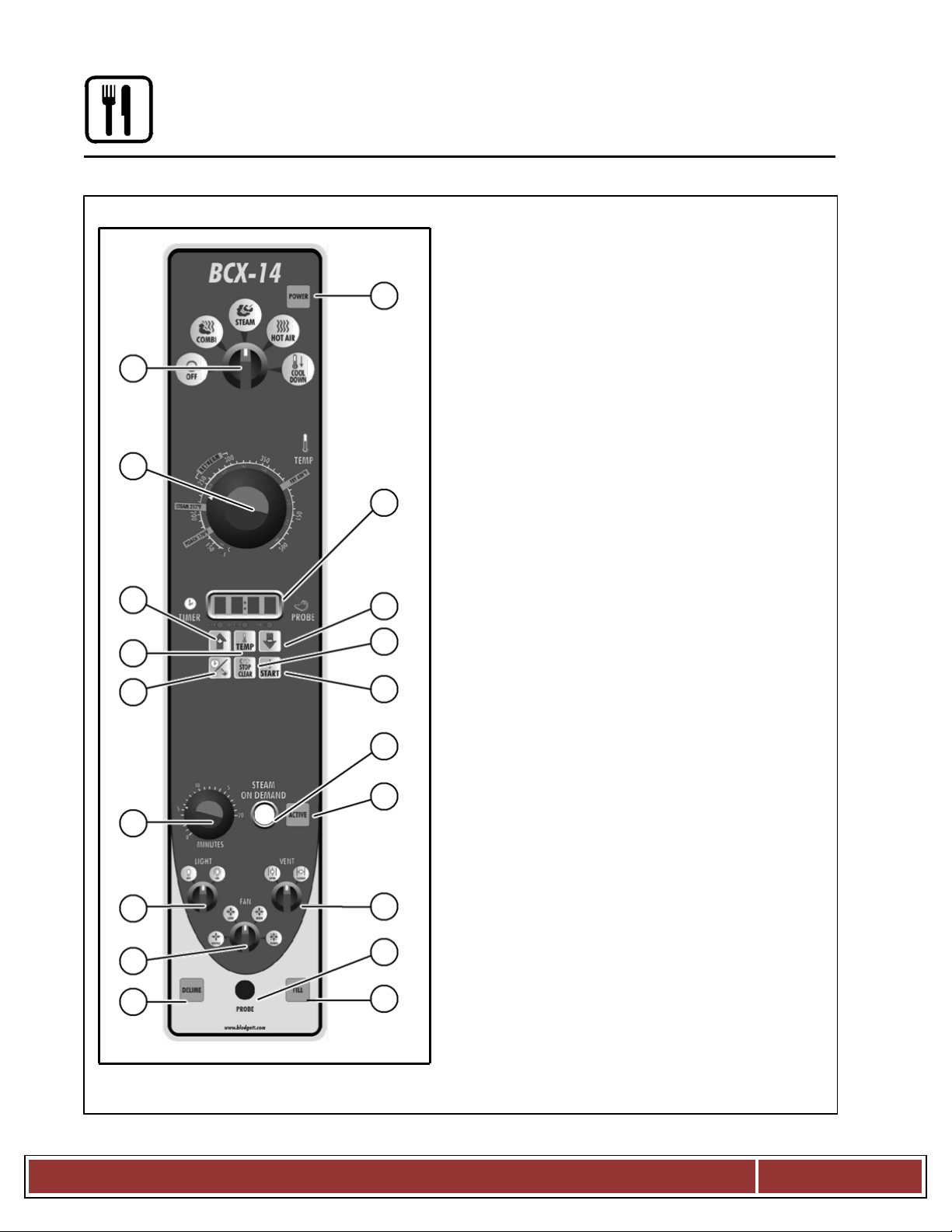
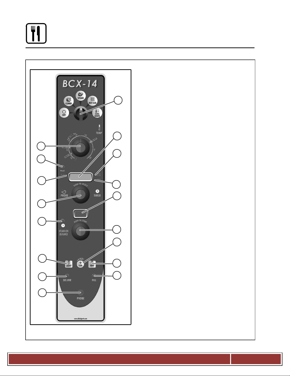
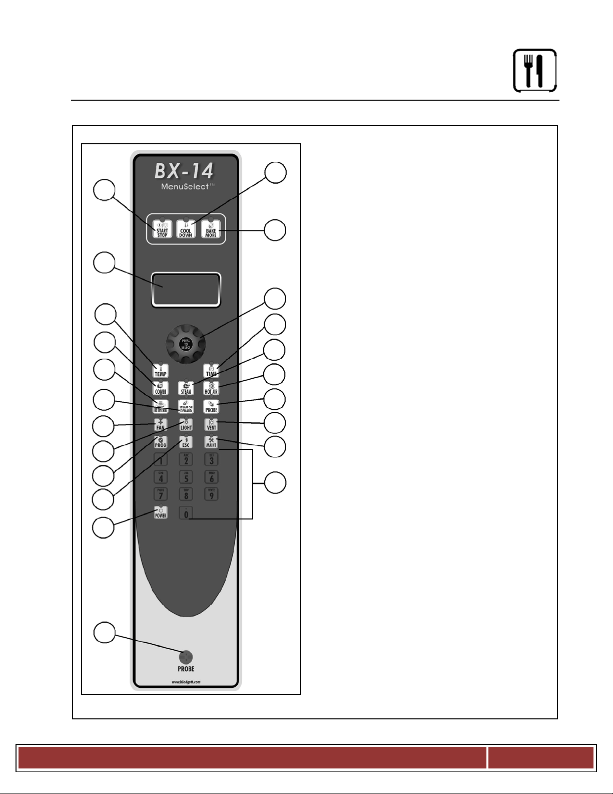
Operation
Standard Controls for Models BCX 14 and BX 14
CONTROLS IDENTIFICATION
1. POWER ON LAMP - when lit indicates
power to the unit is turned on.
2. MODE SELECTOR SWITCH - tur ns power to
the oven on or off. Allows selection of
Steam, Hot Air, Combi or Cool Down Modes.
3. TEMPERATURE DIAL - used to set
desired cooking temperature.
4. DISPLAY - displays time and temperature
in formation.
5. UP & DOWN ARROW KEYS - press to
enter values in the display.
6. ACTUAL TEMP KEY - press to display the
actual probe temperature during core cooking
or actual cavity temperature in timer mode.
7. TIME/PROBE TOGGLE KEY - used to
select either timer or probe cooking.
8. CLEAR/STOP KEY - use to clear or stop
the timer and silence the buzzer.
9. START KEY - press to start the timer.
10. STEAM ON DEMAND TIMER - used to set
duration for steam on demand.
11. STEAM ON DEMAND SWITCH - used to
initiate steam injection cycle.
12. STEAM ON DEM AND LAMP - lights when
steam on demand is activated.
13. LIGHTS SWITCH - used to turn the lights
on and off.
14. CAVITY VENT SWITCH - used to open or
close vent to release steam from cavity.
15. FAN SPEED SWITCH - used to select fan
speed.
16. PROBE CONNECTION - used to connect
the core temperature probe to the control.
17. FILL LAMP - illuminated until the steam
generator is filled with water.
NOTE: Model BX 14 ovens do not have a
18. DELIME LAMP (BCX 14 ovens only) Flashes when steam generator deliming
is needed. Remains steady when deliming
process is active.
CLEAN LAMP (BX 14 ovens only) - Flashes
when the unit has been in use for a
preprogrammed time and needs to be clean
fill lamp.
Blodgett Oven
Page 1
Page 5
Operation
5
5
6
7
8
9
Standard Controls for Models BCX 14 and BX 14
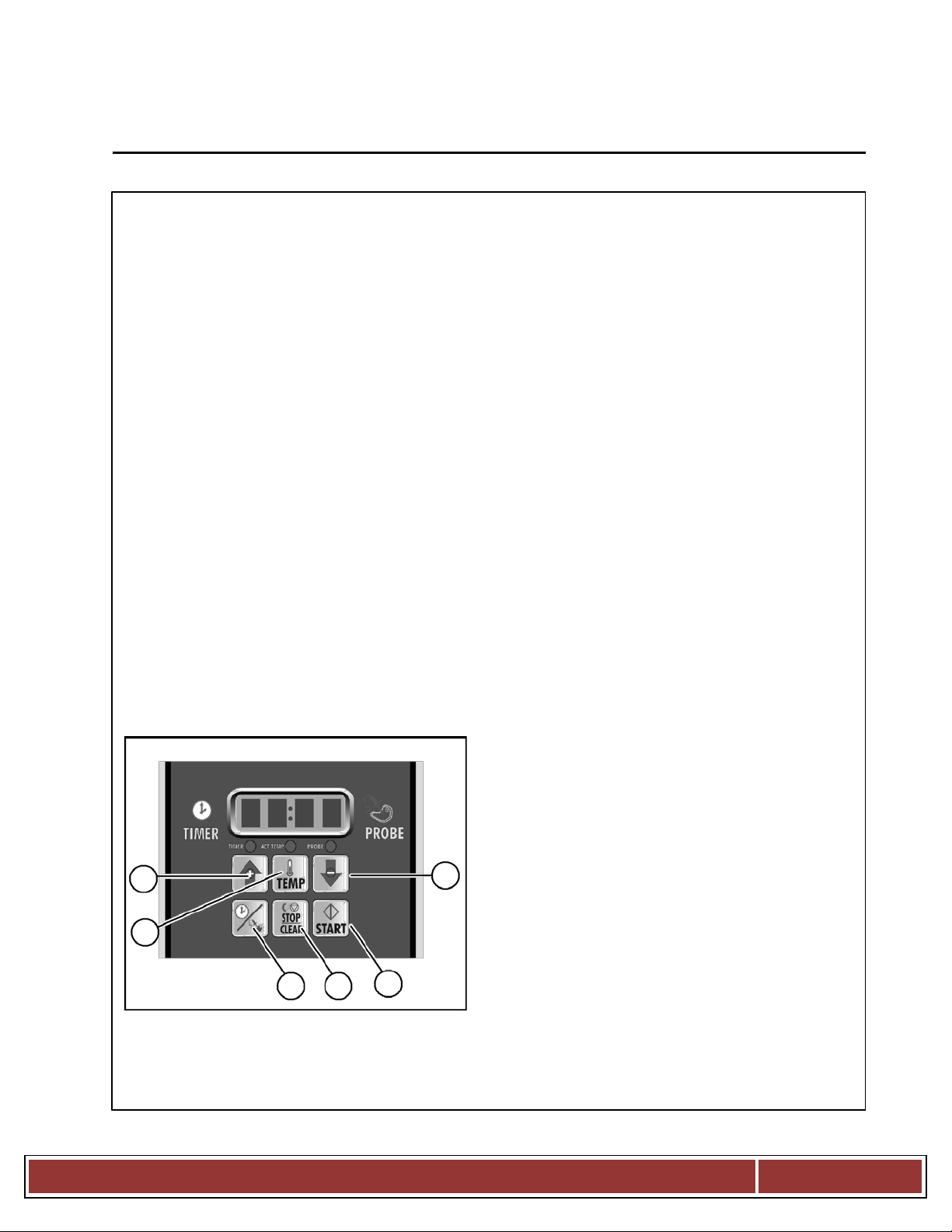
TIMER COOKING
1. Press the TIMER/ PRO B E TOGGLE KEY (7)
to select the timer mode. The TIMER LED
below the display lights.
2. Turn the MODE SELECTOR Switch (2) to
the desired function.
3. Set the TEMPERATURE DIAL (3) to the de
sired cook temperature.
For Steam mode, set the temperature no
higher than 212_F (100_C).
For poaching, turn the temperature dial to
the POACH position, 180_F (82_C).
The optimum temperature for Combi
mode is 300 350_F (149 177_C).
4. When the oven has reached the cook
temperature, load the product.
5. Use the ARROW KEYS (5) to enter the desired
cook time in the display. You can clear the
display by pressing the CLEAR/STOP KEY (8).
6. Press the START KEY (9) to begin the timer.
The temperature, time and mode can be al
tered at any time during the cooking process.
To stop the timer, press the CLEAR/STOP KEY
(8).
7. When the timer reaches 00:00, the buzzer
sounds. Press the CLEAR/STOP KEY (8) to
silence the buzzer. Remove the product.
PROBE COOKING
1. Press the TIMER/PRO BE key (7) to select
the probe mode. The PROBE LED below
the display lights.
2. Use the ARROW KEYS (5) to enter the
desired final cook temperature in the
display. You can clear the display by
pressing the CLEAR/ STOP KEY (8).
3. Insert the core probe into the product. Load
product into the oven and close the door. Be
sure that the terminal end of the core probe is
outside of the oven and clear of the door.
4. Connec t the core probe to the P ROBE C ON
NECTION (16) at the bottom of the control.
5. The display gives the actual core probe
temperature.
6. When the product reaches the final cook
temperature the buzzer sounds.
COOL DOWN
NOTE: The unit can be cooled down rapidly
1. To cool down the oven cavity, open the
for steaming, cleaning, etc.
door and select Cool Down on the MODE
SELEC TOR Switch (2).
Blodgett Oven
Page 2
Page 6
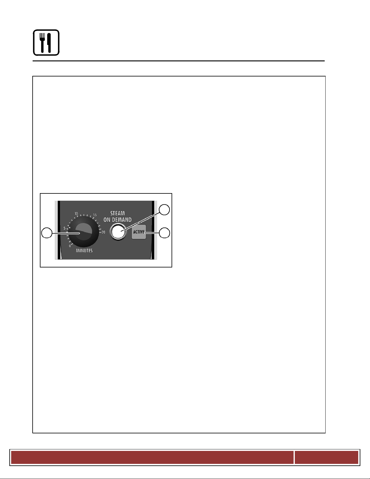
STEAM ON DEMAND
Uses for Steam On Demand:
How to set the Steam On Demand feature:
Most of the ideas came from our creative custom
While in the Hot Air or Combi mode, the unit can
ers. Experiment with this feature on your own and
let us know of any new uses.
be set to steam for a timed period. At the end of the
Add a minute or two at the beginning when
timed cycle the unit reverts back to the original set
D
baking bread for a shiny crust.
ting. Steam On Demand can be used at any time
during the cook cycle.
D
Kick start large loads such as 20 or more chick
NOTE:
Steam On Demand
is not available
in ens. By starting large loads with 5 to 8 minutes
of steam you help the oven recover and cut the
steam mode.
cooking time by more than 10%.
1. Set
the desired •steam
on" time with
the
D
Bake bagels without boiling. By starting raw ba
STEAM ON DEMAND TIMER (10).
gels with 1 to 2 minutes of steam you can
2. Press the STEAM ON DEMAND S WI TCH (11).
achieve a beautiful crust.
The STEAM ON DEMAND LAMP (12) lights.
D
Cream caramel is great at 230_F to 250_F in the
Combi mode using 2 min utes of on demand
steam.
11
D
When cooking chicken wings, try setting the
oven in the Combi mode at 375_F and use 3
minutes of Steam On Demand. This method will
10
12
stop the tips from burning. Total cooking time is
approximately 12 minutes.
D
Pork ribs tend to pull off the bone better when
using 5 to 8 minutes of Steam On Demand. Try
ribs in the Combi mode at 350_F.
Operation
Standard Controls for M odel s BCX 14 and BX 14
Blodgett Oven
Page 3
Page 7
B l o d g e t t O v e n
Page
4
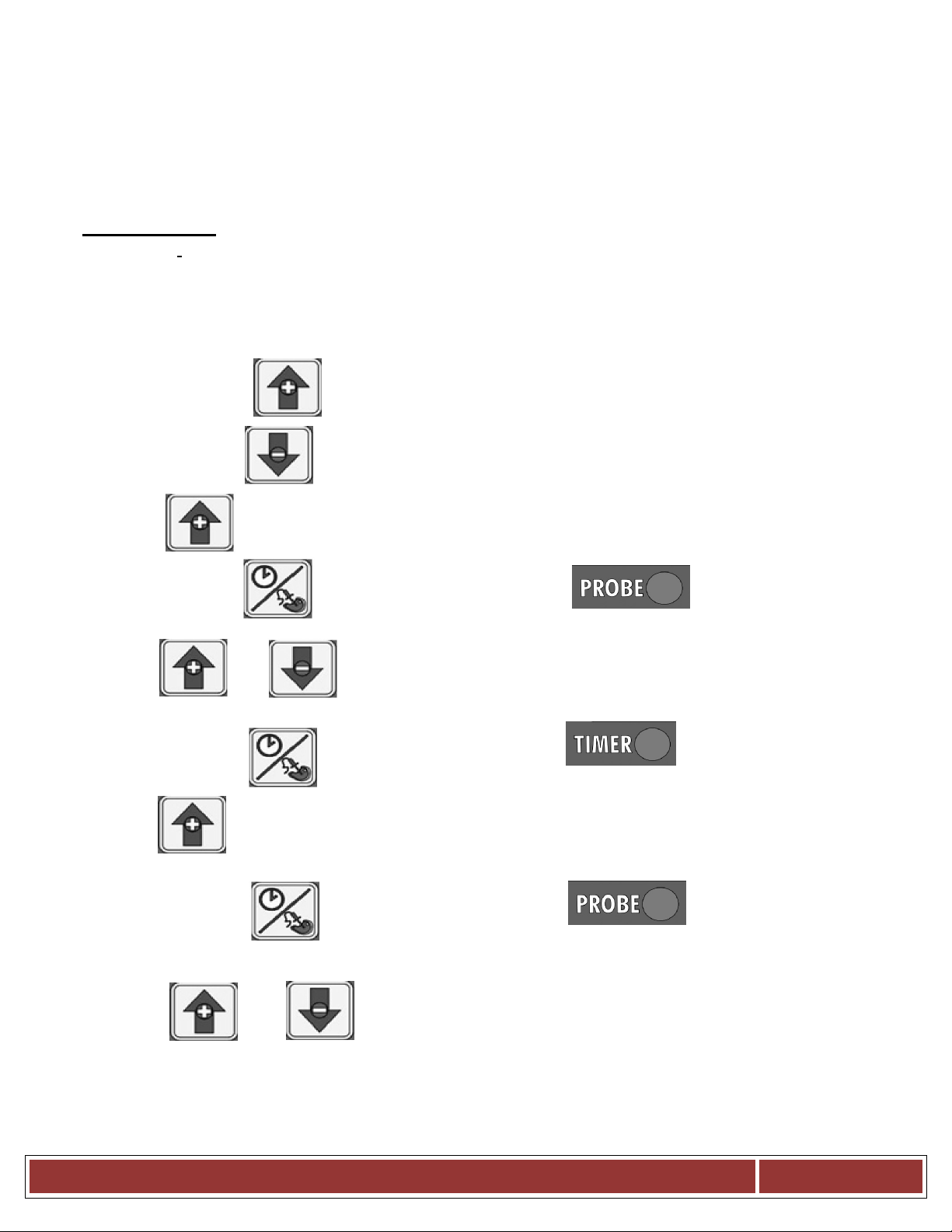
Standard Control Second Level Programming
3. Press and Hold
for 5 seconds and release
or
Combi Manual Control Temp. (BP# 39673)
Instructions For +7° Temperature Offset
Recommended: Read instructions before programming. If each step is not
conducted within 9 seconds, the control will lock up and the programming
sequence will have to be restarted from step 1
1. Power oven off
. Power on oven in Combi Mode
2
4. Press and hold
5. Toggle
6. Press and release
7. Toggle
8. Press and release
9. Press
until "2 X X X" is displayed. Where "X X X" are any number
until Screen displays "P 3 X X" where "X X" are any number
for 5 seconds and release
PROBE LED will begin to Flash
until Screed displays "P 2 0 7"
TIMER LED will begin to flash
10. Press and release PROBE LED will begin to flash
11. Toggle or until Screed displays "P 3 0 0"
12. Do not touch oven for 10 seconds. "0 0 0" will appear. Temp. offset is now programmed
13. Turn off oven and turn back on
Page 8
1
2
3
6
4
5
7
9
8
10
11
13
12
14
15
16
17
Operation
Standard Controls for Models BCX 14 and BX 14
CONTROLS IDENTIFICATION
1. MODE SELECTOR SWITCH - tur ns power to
the oven on or off. Allows selection of
Steam, Hot Air, Combi or Cool Down Modes.
2. DISPLAY - displays time and temperature
in formation.
3. TEMPERATURE DIAL - used to set
desired cooking temperature.
4. HEAT LAMP - lights when the oven is
calling for heat
5. TIMER LED - lights when the cook time is
displayed
6. PROBE ACTUAL LED - lights when the
actual probe temperature is displayed
7. PROBE SETPO INT LED - lights when the
core set point temperature is displayed
8. TIMER/PROBE KNOB - use to select and
set either cook time or probe temperature
9. STEAM ON DEM AND DISPL AY - displays
the steam on demand time
10. STEAM ON DEM AND LAMP - lights when
steam on demand is activated.
11. STEAM ON DEMAND KNOB - use to set
duration for steam on demand
12. LIGHTS KEY - press to turn the oven
lights on and off
13. FAN SPEED KEY - used to select fan speed.
14. CAVITY VENT KEY - used to open or
close vent to release steam from cavity.
15. DELIME LAMP (BCX 14 ovens only) Flashes when steam generator deliming
is needed. Remains steady when deliming
process is active.
16. FILL LAMP - illuminated until the steam
generator is filled with water.
NOTE: Model BX 14 ovens do not have a
17. PROBE CONNECTION - used to connect
the core temperature probe to the control.
fill lamp.
Blodgett Oven
Page 5
Page 9

Standard Controls for Models BCX 14 and BX 14
TIMER COOKING
1. Press the TIMER/PROBE KNOB (8) to select
the timer mode. The TIMER LED lights.
2. T urn the MODE SELECTOR Switch (1) to
the desired function.
3. Set the TEMPERATURE DIAL (3) to the de
sired cook temperature.
For Steam mode, set the temperature no
higher than 212_F (100_C).
For poaching, turn the temperature dial to
the POACH position, 180_F (82_C).
The optimum temperature for Combi
mode is 300 350_F (149 177_C).
4. When the oven has reached the cook
temperature, load the product.
5. Rotate knob to enter the desired cook
time in the display. You can clear the
display by rotating counter clockwise. The
timer begins on its own.
6. The temperature, time and mode can be
altered at any time during the cooking
process.
7. When the timer reaches 00:00, the buzzer
sounds. Press or rotate the TIMER/PROBE
KNOB (8) counter clockwise to silence the
buzzer. Remove the product.
Operation
PROBE COOKING
1. Press the TIMER/PROBE knob (8) to
select the probe set point mode. The
PROBE SET POINT LED (7) lights.
2. Rotate the knob to enter the desired final
cook temperature in the display.
3. Insert the core probe into the product. Load
product into the oven and close the door. Be
sure that the terminal end of the core probe is
outside of the oven and clear of the door.
4. Connec t the core probe to the P ROBE C ON
NECTION (17) at the bottom of the control.
5. The display gives the actual core probe
temperature by pressing the TIMER/PROBE
knob
(8) again.
6. When the product reaches the final cook
temperature the buzzer sounds.
COOL DOWN
NOTE: The unit can be cooled down rapidly
1. To cool down the oven cavity, open the
for steaming, cleaning, etc.
door and select Cool Down on the MODE
SELEC TOR Switch (1).
Blodgett Oven
Page 6
Page 10

Operation
Standard Controls for Models BCX 14 and BX 14
STEAM ON DEMAND
How to set the Steam On Demand feature:
While in the Hot Air or Combi mode, the unit
can be set to steam for a timed period. At the
end of the timed cycle the unit reverts back to
the original set ting. Steam On Demand can
be used at any time during the cook cycle.
NOTE: Steam On Demand is not available in
1. Turn the STEAM ON DEMAND KNOB (11) to
2. Press the STEAM ON DEMAND KNOB (11).
steam mode.
set the desired length of time. The time is
displayed in the STEAM ON DEMAND
DISPLAY
(9).
The STEAM ON DEMAND LAMP (10) lights.
Uses for Steam On Demand:
Most of the ideas came from our creative
customers. Experiment with this feature on
your own and let us know of any new uses.
D Add a minute or two at the beginning when
baking bread for a shiny crust.
D Kick start large loads such as 20 or more
chickens. By starting large loads with 5 to 8
minutes of steam you help the oven recover
and cut the cooking time by more than 10%.
D Bake bagels without boiling. By starting
raw bagels with 1 to 2 minutes of steam you
can achieve a beautiful crust.
D Cream caramel is great at 230_F to 250_F in the
Combi mode using 2 minutes of on demand
steam.
D When cooking chicken wings, try setting the
oven in the Combi mode at 37 5_F and use 3
minutes of Steam On Demand. This method
will stop the tips from bur ning. Total cooking
time is approximately 12 minutes.
D
Pork ribs tend to pull of f th e bone better when
using 5 to 8 minutes of Steam On Demand.
Try ribs in the Combi mode at 350_F.
Blodgett Oven
Page 7
Page 11
Se
rvice
Level Programming
BCX, BX – NEW MANUAL CONTROL
Code: 7378
(The oven needs to be in the “OFF” position)
Press the Timer Dial Till “0000” Is Displayed
Turn the Dial: Scroll the flashing # to (7)000
Press the Dial to Enter Scroll the flashing # to 7(3)00
Press the Dial to Enter Scroll the flashing # to 73(7)0
Press the Dial to Enter Scroll the flashing # to 737(8)
Press the Dial to Enter Scroll to (DIAG) Diagnostics
Press the Dial to Enter
“D-01” Is Displayed
(Cavity Heat Relay)
Press the Dial to Enter Turn Dial CW to “ON”
Turn Dial CCW to “OFF”
Press the Dial to EXIT
(CONTINUE) (FOLLOW STEPS ABOVE)
Scroll the Dial to D-02 Boiler Heat Relay
D-03 Water High Level Switch Status
D-04 Water Low Level Switch Status
D-05 Drain Relay
D-06 Fill Relay
D-07 Steam Relay
D-08 Quench Relay
D-09 Motor-Reversals Relay Gently
D-10 Motor Gently
D-11 Motor Low
D-12 Motor High
D-13 Motor Turbo
D-14 Door Status
D-15 Lights Relay
D-16 Delime Pump Relay
D-17 Software Flash Number
D-18 Software Number
D-19 Software Download Number
B l o d g e t t O v e n
Page 8
Page 12
Se
rvice
Level Programming
BCX, BX NEW MANUAL CONTROL
Code: 7378
(The oven needs to be in the “OFF” position)
D-20 SIB Software Number
D-21 Cavity Set Temperature
D-22 Cavity ACT Temperature
D-23 Cooling Fan Probe Temperature
D-24 Quench Probe Temperature
D-25 Core Probe Temperature
D-26 Boiler Tank Temperature
D-27 Main Switch
D-28 Fan Feedback Input
D-29 Cook Done relay
D-30 Vent relay
D-33 Cool Fan Relay
D-34 Hot Air relay
D-35 Hot Air Enable Relay
D-37 All Relays
D-38 Display and LED Test
END End Of Diagnostic Test
Press Dial to Exit
B l o d g e t t O v e n
Page 9
Page 13
Factory
Level Programming
BCX, BX – NEW MANUAL CONTROL
Code: 3228
(The oven needs to be in the “OFF” position)
Press the Timer Dial Till “0000” Is Displayed
Turn the Dial: Scroll the flashing # to (3)000
Press the Dial to Enter Scroll the flashing # to 3(2)00
Press the Dial to Enter Scroll the flashing # to 32(2)0
Press the Dial to Enter Scroll the flashing # to 322(8)
Press the Dial to Enter “P-01” Is Displayed
Press the Dial to View Turn Dial to: (F)
Press the Dial to Retune Turn Dial to: P-02
(CONTINUE) (FOLLOW STEPS ABOVE)
P-## “ Set To “
(P-02) Cool Down Temp 100F
(P-03) Ready Beep ON
(P-04) Fan Reverse Time 6:00
(P-05) Cook Done Beeper Yes
(P-06) Delime Interval 30 Hours
(P-07) Flush Interval 24 Hours
(P-08) Appliance Type Gas
(P-09) Machine Type BCX / BX
(P-10) Max Steam On Demand
20
(P-11) Min Hot Air Set Point 140F
(P-12) Max Hot Air Set Point 500
(P-13) Min Steam Set Point 85F
(P-14) Max Steam Set Point 225F
(P-15) Max Core Probe Pull Temp 200F
(P-16) Upper Hot Air Hysteresis 1F
(P-17) Lower Hot Air Hysteresis 1F
(P-18) Upper Steam Hysteresis 1F
(P-19) Lower Steam Hysteresis 1F
B l o d g e t t O v e n
Page 10
Page 14

Factory
Level Programming
BCX, BX NEW MANUAL CONTROL
Code: 3228
(The oven needs to be in the “OFF” position)
(P-20) Upper Ready Band 25F
(P-21) Lower Ready Band 10F
(P-22) Cavity Probe Offset 0F
(P-23) Core Probe Offset -2F
(P-24) Spritzer Solenoid Duty Cycle
(P-25) User Response Timeout
33
5
(P-26) Sleep Mode Timeout 1
(P-27) Counter Start Delay 2
(P-28) Quench Probe Yes
(P-29) SCK Address 30
(P-31) ACT Oven Temp Display
No
(P-32) Remote Beeper Yes
Press Dial to Exit Scroll to END
Press Dial to Exit End Of Factory Programming
B l o d g e t t O v e n
Page 11
Page 15
Blodgett Oven
Page 12
Operation
MenuSelect Control for Models BCX 14 and BX 14
CONTROL DESCRIPTION
2
1.
START/ ST O P K E Y press to start, cancel or
pause the bake
1
2.
COOL DOWN KEY initiates oven cool down
cycle
3.
BAKE MORE KEY press at the end of a bake
3
cycle to add additional bake time in one
Minute increments.
4.
DISPLAY displays ti me o r temperature and
4
other information related to oven function and/
Or programming.
5.
DIAL used to enter set points, time, and pro
5
Programmable settings. Also used to select
6
the programmed product.
6.
TEMP KEY used to set or change the bake
7
temperature
8
9
7.
TIME KEY used to set or change the bake
Time.
11
10
8.
COMBI KEY press to enter combi mode
9.
STEAM KEY press to enter steam mode
12
13
16
11.
RETHERM KEY press to enter Retherm
14
mode, this mode uses steam to reheat frozen
or precooked product. Retherm has a
15
19
temperature limit of 250 300_F.
12.
STEAM ON DEMAND KEY used to initiate
17
Steam injection cycle.
20
13.
PROBE KEY press to use core pr obe cooking
18
14.
FAN KEY press to select the fan speed
15.
LIGHT KEY press to turn the lights on and off.
21
16.
VENT KEY press to manually open and close
the oven vent
17.
PROGRAM KEY press to enter product pro
gramming and save programmed settings.
during programming
19.
MAINTENANCE KEY press to enter manager
programming and save programmed settings
22
20.
ALPHA/NUMERIC KEYPAD used to program
Recipes.
21.
POWER KEY used to place control in and out
of standby mode.
22.
CORE PROBE CONNECTION plug core
temperature probe in here when using
Probe cooking
10. HOT AIR KEY press to enter hot air mode
18.
ESCAPE KEY press to back up one step
Page 16

Blodgett Oven
Page 13
Operation
MenuSelect Control for Models BCX 14 and BX 14
OVEN STARTUP
1. Be sure the gas shutoff sw itch and/or circuit
breaker switch below the control panel are
in the on position. The display flashes OFF
PRESS POWER KEY TO START.
NOTE: If the real time clock and auto wake
up functions are enabled the
display reads PRES S POWER KEY
2. Press the POWER KEY (21). The display
reads PREHEAT and the oven heats to the
last manual set temperature in the hot air
mode. The display flashes READY / IDLE
and the alarm beeps 5 times when the
oven is at temperature and ready to bake.
TO START AUTO START.
MANUAL COOKING
1. Turn the DIAL (5) until the display reads
MANUAL.
2. Press the TIME KEY (7). Rotate the dial, or
use the alpha/numeric keypad to enter the
desired bake time. Pr ess the center of the
dial to set the bake time.
NOTE: Time is set in one minute increments
using the dial. To set time in less
than one minute increme nts use the
3. Press the TEMP KEY (6). Rotate the dial, or
use the alpha/numeric keypad to enter the
de sired bake temperature. Press the center
of the dial to set the bake temperature. The
oven preheats to the new temperature.
NOTE: Temperature is set in 5 degree
4. Press the desired mode key, combi,
steam, hot air or Retherm.
If Combi or Retherm are selected, rotate
the dial, or use the alpha/numeric keypad
to enter the desired percentage of steam.
NOTE: Retherm has a temperature limit of
5. When the display flashes READY / IDLE,
open the doors. Load the product.
alpha/ numeric keypad.
increments using the dial. To set
time in less than 5 degree
increments use the alpha/numeric
keypad.
250 300_F.
6. Press the START/STOP KEY (1) to begin the
bake cycle. The timer counts down and the
display alternates between the cooking
mode and the name of the product.
PROGRAMMED COOKING
1. Turn the DIAL (1) until the name of the
product is highlighted. Press the center of
the dial to select. The oven preheats to the
programmed temperature in the correct
cooking mode. The display flashes READY /
IDLE and the alarm beeps 5 times when the
oven is at temperature and ready to bake.
2. Open the doors. Load the product.
3. Press the START/STOP KEY (1) to begin the
bake cycle. The timer counts down and the
display alternates between the cooking
mode and the name of the product.
PROBE COOKING
1. Press the PROBE key (13) to select the
probe mode. The display reads CORE
PROBE COOK & HOLD. Turn the dial to
select either YES or NO . Press the center
of the dial to se lect.
If YES is selected, Cook & Hold has been
enabled. In the Cook & Hold mode, the
oven cavity lowers to the product pull
temperature as the product cooks.
If NO is selected, Cook & Hold has not
been enabled the cavity maintains the
cook temperature.
2. Turn the DIAL to enter the desired product pull
temperature in the display. Press the center of
the dial to save the pull temperature.
3. Press the TEMP KEY (6). Rotate the dial, or
use the alpha/numeric keypad to enter the
de sired bake temperature. Press the center
of the dial to set the bake temperature. The
oven preheats to the new temperature.
NOTE: Temperature is set in 5 degree incre
ments using the dial. To set time in
less than 5 degree increments use
the alpha/numeric keypad.
Page 17

Blodgett Oven
Page 14
MenuSelect Control for Models BCX 14 and BX 14
4. Press the desired mode key, combi,
steam, hot air or Retherm.
If Combi or Retherm are selected, rotate
the dial, or use the alpha/numeric keypad
to enter the desired percentage of steam.
NOTE: Retherm has a temperature limit of
5. Insert the core probe into the product. Load
product into the oven and close the door. Be
sure that the terminal end of the core probe is
outside of the oven and clear of the door.
6. Connect t he core probe to the PR OBE CON
NECTION (22) at the bottom of the control.
NOTE: Do not connected the probe before
7. The display gives the actual core probe tem
perature as well as the oven set temperature.
8. When the product reaches the pull
temperature the buzzer sounds.
9. Press t he START/ST OP KEY (1) to silence
the buzzer.
If using Cook & Hold - The cav ity tempe ra
ture continues to drop to the product pull
temperature and the display counts up,
telling the operator long the product has
been held. Disconnect the core probe and
remove the product when ready.
If not using Cook & Hold - The cavity re
mains at the cook temperature. The
display does not count up. Disconnect the
core probe and remove the product when
the buzzer sounds.
250 300_F.
the cook mode has been selected.
DURING ANY COOK CYCLE
Steam On Demand
While in the Hot Air, Combi or Retherm
modes, the unit can be set to steam for a
timed period of up to 20 minutes. At the end
of the timed cycle the unit reverts back to the
original setting. Steam On Demand can be
used at any time during the cook cycle.
1. Press the STEAM ON DEMAND KEY (12).
2. Rotate the dial, or use the alpha/numeric key
pad to enter the desired steam on demand
Operation
time. Press the center of the dial to
initiate Steam on Demand cycle.
NOTE: Steam on Demand time is set in one
minute increments using the dial. To
set time in less than one minute incre
3. The Steam on Demand LED flashes until
the steam time has expired.
Venting Moisture from the Oven Cavity
1. Press the VENT KEY (16). This manually
opens the vent until the key is pressed
again to close it.
Pause a Bake Cycle
1. To pause a cook cycle, p ress the START/
STOP KEY (1). The LED on the start/stop
key flashes. The bake cycle will pause
until the key is pressed again.
Cancel a Cook Cycle
1. To cancel the cook cycle, press and hold
the START/STOP KEY (1).
ments use the alpha/numeric keypad.
AT THE END OF ANY COOK CYCLE
1. An alarm sounds, the display reads DONE.
2. If more bake time is desired, press the BAKE
MORE KEY (3). This will add an additional one
minute of time for each press of the key.
3. When you are satisfied with the bake, press
the START/STOP KEY (1) to silence the alarm.
Open the door to remove the product.
OVEN SHUTDOWN
1. Press the COOL DOWN KEY (2). The
display reads AUTO COOL DOWN
ACTUAL TEMP. To speed up the cool
down process, open the doors and press
the VENT KEY (16) to open the vent.
2. When the oven has cooled down, the display
reads OFF PRESS POWER KEY TO START.
NOTE: The lights shut off and the vent
closes automaticall y at the end of
the cool down cycle.
Page 18

Blodgett Oven
Page 15
Operation
MenuSelect Control for Models BCX 14 and BX 14
PRODUCT PROGRAMMING
Entering the Program Mode
1. Press the PROGRAM KEY (17). If the control
is password protected, the display reads EN
TER CODE. Use the alpha/numeric keypad
to enter the manager pass code 3124, then
press the center of the dial to enter the
program mode.
Naming a Product Recipe
NOTE: Use the following procedure to name a
new product or edit the name of an
1. For a new recipe, turn the dial to the first open
2. Use the dial to scroll down to Edit Name.
3. Turn the dial or use the alpha/numeric keypad
4. Press the PROG KEY (17). With SAVE
existing product.
product. Press the center of the dial to select.
To edit an existing name, rotate the dial to
the name to be changed. Press the center
of the dial to select.
Press the center of the dial to enter the
edit name menu.
to select the first character. Press the center of
the dial to advance to the next character. Re
peat for all remaining characters.
NOTE: Product names may be up to 10
characters long and can contain
spaces. Use the #1 key to insert
spaces in a recipe name.
NOTE: To select letters using the keypad,
press the appropriate key once if you
need the first letter on the key, twice
for the second and three times for the
third. For example to enter the letter L
press the #5 key three times.
highlighted, press the dial to save the
product name.
Programming a Product Recipe
NOTE: The control can hold 99 recipes. Each rec
1. Turn the dial to highlight the name of the
2. The display reads PRODUCT NAME: ST AGE 1.
3. Rotate the dial, or use the alpha/numeric key
4. Rotate the dial to select the desired
5. Rotate the dial, or use the alpha/numeric
6. Rotate the dial to select the desired fan speed.
ipe may have up to 6 cooking stages.
product to be programmed. Press the
center of the dial to select the product.
Press the center of the dial to select the stage.
pad to enter the desired bake time. Press the
center of the dial to set the bake time.
NOTE: Time is set in one minute increments
using the dial. To set time in less
than one minute increme nts use the
alpha/ numeric keypad.
cooking mode. Choose from combi,
steam, hot air or Retherm. Press the
center of the dial to set the cook mode.
If Combi or Retherm are selected, rotate
the dial, or use the alpha/numeric keypad
to enter the desired percentage of steam.
key pad to enter the desired cook
temperature. Press the center of the dial
to set the bake temperature.
NOTE: Temperature is set in 5 degree incre
ments using the dial. To set time in
less than 5 degree increments use
the alpha/numeric keypad.
NOTE: Retherm has a temperature limit of
250 300_F.
Choose from gentle, low, high or turbo. Press
the center of the dial to set the fan speed.
Page 19
BCX, BX – MENUSELECT CONTROL
Service Level Programming
(The oven needs to be in the “ON” position)
Press the Maint Key Scroll to “SERVICE”
Press the Dial to Enter Enter Service Code “7378”
Press the Dial to Enter Scroll to “Diag Output”
Press the Dial to Enter
Press and hold # button to test
Temp Heat
Combi Fan Speed Gentle Fwd
Fan Fan Speed Low Fwd
Prog Fan Speed High Fwd Forward
1 Fan Speed Turbo Fwd
4 Fan Speed High Rev
7 Light
Light Spritzer
ESC Cooling Fan
2 Vent
5 Hot Air
8 Hot Air Enable
Component Function Test:
0 Quench
Hot Air Delime
Probe Heat Boiler
Vent Fill
Maint Drain
(Press the Dial to Exit) Scroll to “Diag Input”
Press the Dial to Enter
Press and hold buttons to test
Temp Fan Error
Combi Door
Fan Cavity Probe Temp
Component Function Test:
B l o d g e t t O v e n
Page 16
Page 20
BCX, BX MENUSELECT CONTROL
Service Level Programming
(The oven needs to be in the “ON” position)
Prog Cooling Fan Probe Temp
1 Quench Probe Temp
4 Core Probe Temp
7 Boiler Probe Temp
Steam Water Hi Level SW
Steam on Demand Water Low Level SW
“Press the Dial to Exit” Scroll to Exit
Press the Dial to Exit Scroll to Exit Press (“Dial”)
Factory Level Programming
(The oven needs to be in the “ON” position)
Press the Maint Key Scroll to Factory Program
Press the Dial to Enter Enter the Factory Code “3228”
Press the Dial to Enter Scroll to “Appliance Type”
Press the Dial to Enter Turn Dial to set Gas or Electric
Press the Dial to Enter
Scroll to “Cavity Probe Offset”
Press the Dial to Enter Turn the Dial to Set the Offset
Press the Dial to Enter
Scroll to ”Core Probe Offset”
Press the Dial to Enter Turn the Dial to set the Offset
Press the Dial to Enter
Scroll to Exit
Press the Dial to Exit Scroll to Exit again
Press the Dial to Exit the
Program Level.
B l o d g e t t O v e n
Page 17
Page 21

B l o d g e t t O v e n
Page
18
Notes:
Page 22

BCX14E
BCX14E TROUBLESHOOTING GUIDE
In this troubleshooting guide, the schematic is
broken down into areas. This allows the oven to be
checked in sections.
When troubleshooting, tilt the control panel down
for access to use your voltmeter. The main control
circuit voltage for all BX / BCX and CNVX model
ovens is 24DC volts. Once the problem is
determined be sure to power the oven down before
disconnecting connections.
NOTE: Always troubleshoot Combi ovens in the
following sequence: COOL DOWN, HOT AIR,
STEAM and then COMBI. Reference the text that
follows with the appropriate troubleshooting
schematic to help you troubleshoot each mode.
DC VOLTAGE TEST POINTS
1. At the DCV power supply should be (2)
+24Dcv and (2) -24Dcv_Rtn connections, when
115Acv is applied to the power supply there
will be a small green light on at the power
supply and it should always have 24Dcv
between the plus and minus points.
2. Locate the logic board small connector J1 using
your voltmeter checking for 24Dcv between
terminals (J1-1) 24Dcv Rtn
verify true 24Dcv input to enable the logic
board during the power up.
3. The J1 connector between (J1-1) -24Dcv Rtn
and (J1-4) +24dcv will be the best (Test points).
When troubleshooting any problems, if your
looking for a low signal test between (J1-4)
+24Dcv RD to the low input searching for, or if
your looking for a +24Dcv_H positive leg of
power check between (J1-1) -24Dcv_Rtn and
the high signal searching for. (See FIGURE 1)
4. Checking for 24Dcv at the IFB relay board J7
connector between (J7-1) to (J7-2).
5. NOTE: While troubleshooting the 24Dcv circuit
with the wire schematic you will see that most
all of the control switching is to a (Low)
24Dcv_Rtn. Also while reviewing the wire
schematic you will see the wires labeled as a
(High) or (Low) input such as (Oven_On_L) for
the low input and (Door_Closed_H) for a high
input/output.
to (J1-4) +24Dcv to
6. Acv/Dcv. See the incoming power supply flow
chart (FIGURE 1).
NO OPERATION WITH THE MODE SWITCH
IN COOL DOWN
1. Verify that the control panel circuit breaker is in
the on position.
2. Check the outlet for proper power supply.
3. Remove the LH body side panel and inspect the
motor inverter control to see if it is powered up
with 115Acv and if there are any error codes
present if so, see the attached fault code list for
troubleshooting. The display will show 00 if
there are no fault codes present while the motor
is not running. If no codes are present continue
or if a code is present see the programming fault
code troubleshooting flow chart section 4
(FIGURE 1) page 9-1.
4. Locate the logic board small vertical RH
connector J1 using your voltmeter checking for
24Dcv between (J1-4) to the mode switch
terminal # 4 voltage should be present, if not
investigate the mode switch. Also check
between the J1 connector (J1-4) to the inverter
connector BK-12 wire at CM2 for 24Dcv, if no
voltage check the IFB relay board connector J3.
5. To bypass the mode switch and wire harness
use your voltmeter set to the 10amp red fuse
side with the black in COM then set your meter
to DC amps, now your meter is a fused jumper
wire. Now jump between the logic board J1
connector (J1-1) to the motor speed inverter
GY-19 low signal at terminal # 2 of the inverter.
This should activate the inverter power up. See
the cool down operation troubleshooting flow
chart (FIGURE 3).
NO OPERATION WITH THE MODE SWITCH
IN HOT AIR
1. Verify that the convection motor is running with
the door fully closed. If not see door switch
troubleshooting flow chart (FIGURE 7).
2. Verify that the thermostat has powered up,
counted down and displaying a set temperature
along with the heat indicator light activated.
3. Remove the LH body side panel and tilt the
control panel down for troubleshooting access.
B l o d g e t t O v e n
Page 19
Page 23

BCX14E
BCX14E TROUBLESHOOTING GUIDE
4. Checking for logic board input/output LED
indicators, in the hot air mode the amber input
LED’s #6 and #9 need to be on along with the
green output LED #13. Verify LED’S with the
logic board LED designation flow chart
(FIGURE 11).
5. Also look for LED indicator inputs at the (IFB)
relay board, the CR3 relay LED (D31), CR2
relay LED (D21) and the CR1 relay LED (D11)
will all need to be on. If not check all
connectors and the 24Dcv inputs at the J7
connector per the wire schematic. Verify
LED’S with the IFB LED indicator designation
flow chart (FIGURE 12).
6. If all of the above are good continue testing
checking at the lower of the two Dcv 24V
power supplies for a lighted small green light
along with checking for 24Dcv output.
7. Next go directly the (K1) hot air contactor and
measure the coil voltage between A1 & A2 for
24dcv volts, if not check A1 at the coil to the J1
connector at the logic board J1-1 for 24dcv and
if okay check A2 coil to logic board J1-4 for
24dcv.
8. In either case no voltage go the IFB relay board
and check for 24dcv at J4 connector between
J4-1 and J4-2 for 24dcv from the power supply,
good check from J4-6 to logic board J1-1 for
24dcv output to the contactor coil.
NO OPERATION WITH THE MODE SWITCH
IN STEAM
1. Verify that the convection motor is running
with the door closed. If not see door switch
troubleshooting flow chart (FIGURE 7).
2. Verify that the thermostat has powered up,
counted down and displaying a set temperature
along with the heat indicator light activated.
3. Remove the LH body side panel and tilt the
control panel down for troubleshooting access.
4. Check for logic board input/output LED
indicators, in the steam mode the amber input
LED’s # 3 and # 6 need to be on along with the
green output LED # 10. Verify LED’S with the
LED designation flow chart (FIGURE 11).
5. Look for LED indicator inputs present at the
IFB relay board, looking for the CR3 relay
LED (D31), CR2 relay LED (D21) and the
6. CR7 relay LED (D71) should be on. If not
check IFB connector J7 between (J7-1) to (J7-
2) for 24Dcv input see wire schematic. Verify
LED’S with the IFB LED indicator flow chart
(FIGURE 12).
7. If all of the above is good continue testing
checking at the lower of the two power
supplies for a lighted small green light along
with checking for 24dcv output.
9. Next go directly the (K2) steam contactor and
measure the coil voltage between A1 & A2 for
24dcv volts, if not check A1 at the coil to the J1
connector at the logic board J1-1 for 24dcv and
if okay check A2 coil to logic board J1-4 for
24dcv.
10. In either case no voltage go the IFB relay board
and check for 24dcv at J6 connector between
J6-1 and J6-2 for 24dcv from the power supply,
good check from J6-5 to logic board J1-1 for
24dcv output to the contactor coil.
NO OPERATION WITH THE MODE
SWITCH IN COMBI
1. Verify that the convection motor is running with
the door fully closed. If not see door switch
troubleshooting flow chart (FIGURE 7).
2. Verify that the thermostat has powered up,
counted down and displaying a set temperature
along with the heat indicator light is activated.
3. Remove the LH body side panel and tilt the
control panel down for troubleshooting access.
4. Checking for logic board input/output LED
indicators, in the Combi mode the amber input
LED’s #2 and #6 need to be on along with the
green output LED #13 and then #10 for 45
seconds intervals of steam while in Combi.
Verify LED’S with the LED designation flow
chart (FIGURE 11).
5. Look for LED indicator inputs at the (IFB) relay
board, looking for the CR3 relay LED (D31),
CR2 relay LED (D21), CR1 relay LED (D11)
will all need to be on and CR7 relay LED (D71)
will be on during a 45 second steam on time. If
not check all connectors and the 24Dcv input at
the J7 connector per the wire schematic #50277
between (J7-1) to (J7-2). Verify the LED inputs
with the IFB LED indicator designation flow
chart (FIGURE 12).
B l o d g e t t O v e n
Page 20
Page 24

BCX14E
BCX14E TROUBLESHOOTING GUIDE
8. If all of the above is good continue testing
checking at the lower of the two power supplies
for a lighted small green light along with
checking for 24dcv output.
9. Next go directly the (K1) hot air contactor and
measure the coil voltage between A1 & A2 for
24dcv volts, if not check A1 at the coil to the J1
connector at the logic board J1-1 for 24dcv and
if okay check A2 coil to logic board J1-4 for
24dcv.
10. Hot air contactor will mostly control the Combi
mode along with the logic board switching
from hot air contactor to steam contactor for on
and off for about 45 seconds as long as the
boiler has come above the preheat temp of 180°
already.
11. In either case no voltage go the IFB relay board
and check for 24dcv at J4 connector between
J4-1 and J4-2 for 24dcv from the power supply,
good check from J4-6 to logic board J1-1 for
24dcv output to the contactor coil.
NO FILLING OF THE STEAM BOILER
1. Verify the water pressure and flow of the water
pressure through the pressure regulator.
2. Verify that the control panel circuit breaker is in
the on position.
3. Check for 24Dcv at the power supply with the
mode switch in the off position, green light ON.
4. Shut the water supply off, then at the IFB board
locate the flush switch in the center RH of the
relay board and press and hold it for 45 seconds
while checking for water flow out the drain.
5. After doing so disconnect the float wires (mark
as needed) check for continuity, both floats are
normally closed and open when are floats full.
6. If floats are closed re-connect the float wires
and turn the water supply back on. At this point
with the mode switch still in the off position the
logic board LED indicators amber input # 8 and
green output # 15 should be on activating the
fill solenoids.
7. No water filling yet check the IFB fill enable
CR8 relay LED (D81), if not on check the relay
board J8 connector at (J8-1) to (J8-2) for 24dcv.
8. See the float switch troubleshooting flow chart
(FIGURE 8).
OVER FILLING OF THE STEAM BOILER
1. Turn off the control panel circuit breaker to see
if the water over filling continues in the oven.
2. If water stopped when power was off, turn the
circuit breaker back on and check for the fill
light on the control panel and look at the logic
board for LED indicators. If LED’s amber
input # 8 and green out put # 15 are on this
would indicate the (LLC) low level cut float is
in the closed position and will not open. Repair
or replace floats switch as needed.
3. Check both float switches for normally closed
when empty and open when steam generator is
full. (If they do not open repair or replace floats
as needed.
4. See the float switch troubleshooting flow chart
(FIGURE 8).
CONVECTION MOTOR WILL NOT
REVERSE DIRECTIONS.
1. This oven comes equipped with the feature of
the convection motor reversal after every six
minutes of motor run time in all modes except
for the cool down mode.
2. When any mode but cool down is activated the
motor should start up counter clockwise.
3. Check for 24dcv at the TMR1 timer between
A1 to A2. When verified test between A1 to #
16 for 24dcv after six minutes 24dcv will
switch from terminal #16 to # 18. (If voltage
does not switch remove the wire from #18 and
retest the timer for switching.
4. What ever the out come the motor speed
inverter is looking for a 24Dcv_Rtn_L input
from the timer to either terminal #5 or #6 at the
motor speed inverter to reverse directions.
5. See the motor reverse troubleshooting flow
chart (FIGURE 9).
DOOR SWITCH TROUBLESHOOTING
1. The door switch is a proximity switch that is
activated by the metal of door when it is closed
therefor-proper adjustment is needed.
2. The door switch is located at the lower left
corner with the door open the switch will be
B l o d g e t t O v e n
Page 21
Page 25

BCX14E
BCX14E TROUBLESHOOTING GUIDE
protruding out ½ inch, inspect the switch for
any damage and for proper adjustment.
3. There are three wires from the door switch that
go directly to the IFB connector J5.
4. Check for 24Vdc active at the IFB relay board
at the connector J5 from (J5-3) to (J5-4).
5. If the door switch has 24Vdc going to it when
the door is closed the back of the door switch
will light up to indicate the door switch has
been activated and the blower motor should
began running.
6. At this point check for +24Vdc_H output from
the IFB connector J5 from (J5-2) to (J5-5). If
the voltage is present and the door switch is
closed now look for an LED indicator at the
IFB relay board CR2 relay (D21). See door
switch troubleshooting flow chart (FIGURE 7).
DRAIN VALVE TROUBLESHOOTING AND
OPERATION
1. The drain valve will always remain in the
closed position during all mode operations.
2. If the oven boiler is below 150 degrees and
after somewhere between 3-5 hours of non use
the logic board will activate the drain valve
motor to open and drain the boiler down then it
will close the drain valve motor and then refill
the boiler to the low level float switch.
3. When troubleshooting the drain valve motor
operation there is a small stem switch on the
right side of the IFB relay board. This can be
depressed to activate the drain valve motor,
while holding the switch (In) the drain valve
motor open fully to drain the boiler down and
when the switch is released the drain valve
motor will return to the normally closed
position. (Caution of a hot boiler).
4. See Troubleshooting (FIGURE 10).
NO STEAM ON DEMAND
1. While depress the steam on demand button
verify at the logic board LED indicators amber
input # 4 and green output # 12.
2. No LED input check for a 24dcv-Rtn_L input
to the logic board at the J3 connector at (J3-7)
of the logic board. If there is no input
24Dcv_Rtn_L signal go to the steam on
demand switch SW10 and check for a
24Dcv_Rtn_L signal at BK-7 of the switch to
Logic Board J1 connector (J1-4).
NO DELIME PUMP OPERATION
1. The delime pump can be tested with the oven
placed in the cool down, when you press and
hold the steam on demand button for a few
several seconds 24Vdc should be applied
directly the delime pump.
2. Verify when you activate the steam on demand
button, at the logic board LED indicators
amber input #4 and green output #12 light up.
3. If no voltage is found during the first test at the
delime pump, go to the IFB relay board J8
connector and test between (J8-1) to (J8-2)
24Vdc should be present.
4. Continued testing, check for 24Vdc to the R-12
wire at the delime pump testing from the J8
5. IFB connector (J8-2) to the R-12 wire. If
voltage is good this would mean the red
+24Vdc is good now check between the V-13
wire at the delime pump to check the
24Vdc_Rtn_L input from the J8 connector test
between (J8-1) to V-13. If no voltage inspect
the IFB relay board for damage.
MOTOR SPEED INVERTER PRGRAMING
1. Every motor speed inverter has been
programmed from the factory however for
some reason if it lost it’s programming it can
be reprogrammed manually.
2. You will see on the inverter drive the green
(Run) and red (Stop/Reset) buttons, below
those two buttons there is a door that will open
up to gain access to the programming keys
need to reprogram the inverter drive.
3. Behind the access door the programming keys
are (FUNC.), (#1⇑⇑⇑⇑ ), (#2 ⇓⇓⇓⇓) and (STR).
4. To program the inverter drive back to the
factory settings (See the attached programming
flow chart (Figure 3).
5. See Inverter fault code & stored fault codes
flow chart section 4 (FIGURE 1) page 4-1.
B l o d g e t t O v e n
Page 22
Page 26
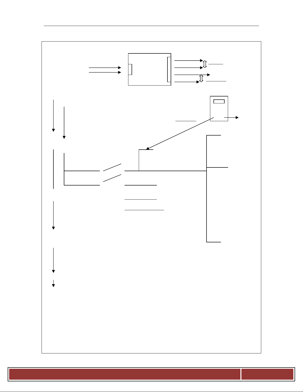
BCX14E
BCX14E INCOMING POWER SUPPLY CHECK
24dcv Power Supply
115 24dcv
Incoming ACV + + 24dcvRtn A. 24Vdc to J7 at (IFB)
L -
N + 24dcv
- 24dcvRtn B. 24Vdc to J1 connector
Switch Closed
+24Vdc
24Vdc Rtn
Logic Board
J1 Conn.
Incoming powers from the DC power supply control (B.24Vdc.) J1-4
Red
J1 ∧ TMR1 (Timer)
P1 ∧ ∧ J1 A2
∧ P1< < < Oven_On_L
1+3 #2 Logic Board
0 0 J1-6
Logic Board J3
5,7,9 0 0 #6 Combi (J3-1)
J1-4 Logic board 0 #8 Steam (J3-2)
0 #10 Convection (J3-6)
J2-2 Temp control TC1
+24Vdc (Temp Control)
J2-1
Control panel lights
(DS5)
Pwr_On
(DS6)
Heat_Demand
(DS9)
Steam_Demand
(DS8)
Delime
(DS7)
Low_Water
+24
Dcv
B l o d g e t t O v e n
Page 23
Page 27

BCX14E
BCX14E LOGIC BOARD ( J1 ) CONNECTOR VOLTAGE TEST POINTS
LOGIC BOARD VOLTAGE TEST POINTS AT (J1 CONNECTOR)
From (J1-1) BK 24Dcv_Rtn_L to (J1-4) RD +24Dcv_H
(Always live with circuit breaker On)
Trouble shooting test points!
Your volt meter leads should insert
right into the LH side of the J1
connector through a hole provided
from the factory for test points.
This connector will provide the
best test points while testing for a
24Dcv_Rtn_L, with your meter
Red lead into (J1-4)-RD +24Dcv
and your Black lead testing for the
24Dcv_Rtn_L.
Or your meter Black lead into the
(J1-1)-BK 24Dcv_Rtn_L and your
Red lead testing for a +24Dcv_H.
24DCV
- +
J3
J4
J1-4 RD
J1
J1-1 BK
J
B l o d g e t t O v e n
Page 24
Page 28

BCX14E
T3
BCX14E COOL DOWN MODE OPERATION TROUBLESHOOTING
J3
Connector
24Dcv_Rtn_L 24Dvc_Rtn_L
Switch Closed
1&3 4
Mode_Sw
+24dcv
- +
J1-4
J1 Connector
Logic Board
Inverter Drive
24Dcv_L
MOTOR
J3-1 Motor_Fwd_Ena
J3-2 Motor_Rev_Ena
J3-3 Spd_Sel_0
J3-4 Spd_sel_1
J3-5 Drv_@SetSpd
J3-7 Inv_Com
ACV
115Ac
NEU
1
2
3
4
5
L
11
12
CM2
T1
T2
B l o d g e t t O v e n
Page 25
Page 29

BCX14E
J1-6
Com
J4-6 J4
-
2
BCX14E HOT AIR FLOW CHART
+24Vdc_H
Logic Board
24Vdc_Rtn_L J1 TMR1
CR1
24Vdc_Rtn A2 15
+24Vdc
Oven On Oven_On_L
Logic Board
Logic Board J4
1+3 o o #2 J3
Mode_Sw
5,7,9 o o #10 (J3-6) Heat_Demand_In
(Switch Closed)
TC1
Logic Board J2-1
J1-4 Red
24Dcv
- +
J1 Connector
IFB
Conv_Heat_Ena_L
+24Vac_H
24Vac_Rtn_L
Pwr_On K1
Heat_Demand
Steam_Demand
24Acv
- +
-24V_DcvRtn
Power supply
Delime
T1
Transformer
24Vac_Rtn
# 6
J1-1
J1-4
Input
Amber
LED
# 6 &
# 9
Green
Output
LED
# 13
J4-2
J4-1
24Vdc_Rtn
No
J1-7
J4-1
Hot Air
CONTACTOR
A1 #7
A2 #8
B l o d g e t t O v e n
Page 26
Page 30

BCX14E
J1-6
#7
#14
Com
J6-5 J6
-
2
BCX14E STEAM FLOW CHART
+24Vdc_H
Logic Board
24Vdc_Rtn_L J1 TMR1
CR1
24Vdc_Rtn_L A2 15
+24Vdc_H
Oven On Oven_On_L
Logic Board
Logic Board J4
1+3 o o #2 J3
Mode_Sw
5,7,9 o o #8 (J3-2) Heat_Demand_In_L
(Switch Closed)
TC1
Logic Board J2-1
24Dcv
- +
J1-1 BK
J1 Connector
IFB
Boiler_Ena_L
+24Vac_H
24Vac_Rtn_L
Pwr_On T2
Heat_Demand
Steam_Demand
24Acv
- +
24Dcv_Rtn
Delime T2 Transformer Power supply
24Vac_Rtn # 6
J1-1
J1-4
Input
Amber
LED
# 3 &
#6
#11
Green
Output
LED
# 10
J4-6
J4-1
24Vdc_Rtn
No
J1-12
J6-1
STEAM
CONTACTOR
A1 #7
A2 #8
B l o d g e t t O v e n
Page 27
Page 31

BCX14E
J1-6
Com
J4-6 J4
-
2
A2 #8
BCX14E COMBI FLOW CHART
+24Vdc_H
Logic Board
24Vdc_Rtn_L J1 TMR1
CR1
24Vdc_Rtn_L A2 15
+24Vdc_H
Oven On Oven_On_L
Logic Board
Logic Board J4
1+3 o o #2 J3
Mode_Sw
5,7,9 o o #6 (J3-1) Heat_Demand_In_L
J2-1
IFB Heat_Ena_L
Boiler_Ena_L
+24Vac_H
24Vac_Rtn_L
Pwr_On T2
Heat_Demand
Steam_Demand T1
Delime
- 24vDcv_Rtn
J1-1
J1-4
Input
Amber
LED
# 2 &
# 6
#7
#11
Green
Output
LED # 13
& #10
J4-6
J4-1 J4-2
24Vdc_Rtn
No
J1-7
J1-12
J6-5
J4-1
Hot Air
CONTACTOR
A1 #7
Steam
CONTACTOR
A1 #7
A2 #8
B l o d g e t t O v e n
Page 28
Page 32

BCX14E
BCX14E DOOR SWITCH TROUBLESHOOTING
IFB
Door_Sw_Pwr_H
Door_Sw_Rtn_L
Door_Closed_H
J1-1 BK
J1 Connector
Logic Board
BK J5 Connector
BR BL
Output when door is closed
Switch will be lighted
Logic Board
J1 Connector
J1-1 BK +24Dcv_H
TMR1
IFB 13
Door_Closed_H
Y-5
CR1
Y-10
A1
J2 Connector
+24Dcv
- +
+24Dcv
- +
Y-10
J2-1
J5-3
J5-4
J5-5
B l o d g e t t O v e n
Page 29
Page 33

BCX14E
BCX14G FLOAT SWITCH TROUBLESHOOTING
J8
+24Dcv_H
24Dcv_Rtn
IFB
Relay Board
SW3
The Flats are normally closed
HI_Lvl_Float_Sw
and open when the boiler is
full.
V-3 o o R15
+24Dcv should always be
applied to the float wires R-15
that activates the fill solenoid’s
relay at the IFB which applies a
24Dcv_Rtn_L to complete the
o o R15
power circuit for the water fill
BL-6
solenoid’s till the float opens.
Troubleshooting the floats drain
SW2
the boiler with the flush switch
Lo_Lvl_Float_Sw
at the IFB and check both floats
to verify normally closed and
after boiler fill up floats open.
+24Dcv_H
24Dcv_Rtn_L V-5 R-14
Fill_Solenoid_A
24Dcv_Rtn_L BL-10 R-14
Fill_Solenoid_B
J8-1
J8-2
J8-3
J8-4
J8-5
J8-6
B l o d g e t t O v e n
Page 30
Page 34

BCX14E
T3
#6
BCX14E MOTOR REVERSE DIRECTION TROUBLESHOOTING
J3
Connector
IFB
24Dcv_Rtn_L
1&3 2
Mode_Sw
18 15
16
A2 A1
J1
J1-3
24Dvc_L
J1-4
I
F
B
Door_Closed_H
J2
J1-1
Inverter Drive
I
F
B
CR1
GY-12
24Dcv_L
14 13
#9
#5
#10
MOTOR
J3-1 Motor_Fwd_Ena
J3-2 Motor_Rev_Ena
J3-3 Spd_Sel_0
J3-4 Spd_sel_1
J3-5 Drv_@SetSpd
J3-7 Inv_Com
ACV
115Ac
NEU
1
2
3
4
5
L
11
12
CM2
T1
T2
B l o d g e t t O v e n
Page 31
Page 35

BCX14E
BCX14E DRAIN VALVE OPERATION TROUBLESHOOTING
J8
+24Dcv_H
24Dcv_Rtn
IFB
Relay Board
Drain_Closed_H
Drain_Open_H
The drain valve in its normally
closed position should always
have 24Dcv_Rtn_L input along
with the +24Dcv_H out put
from the IFB J8 connector to
the motorized drain valve.
The drain valve opens when the
+24Dcv_H switches from J8-8
BK-20
to J8-9 then it should switch
back to close.
The drain valve will only open
when the logic board sends an
output signal to the IFB after
oven is cold and 4-5 hours of
non use, or when the flush
switch is activated at the IFB.
24Dcv_Rtn_L
OR-17
5
1
Y-9 3
J8-1
J8-2
J8-8
J8-9
B l o d g e t t O v e n
Page 32
Page 36

BCX14E
LOW FLOAT LEVEL LED'S
BOILER PREHEAT TO 185F
AMBER
- INPUT LED'S
AMBER
- INPUT LED'S
GREEN OUTPUT LED'S
GREEN OUTPUT LED'S
HOT AIR MODE LED'S
STEAM MODE LED INDICATORS
AMBER
- INPUT LED'S
AMBER
- INPUT LED'S
GREEN OUTPUT LED'S
GREEN OUTPUT LED'S
BCX14E LOGIC BOARD LED INDICATOR DESIGNATIONS
LED On = INPUT
LED
Flush Disable (above 140F) J2-2
1
Combi Mode J3-1
2
Steam Mode J3-2
3
Steam On Demand J3-7
4
Spare input J3-8
5
Heat Demand J4-1
6
Boiler High limit J4-5
7
Boiler Lo_Lvl_Float
8
Convection Heat J3-6
9
DESCRIPTION
LED On = OUTPUT
10 Boiler Heat On
Delime lamp Flashing / Delime Oven
11
Steam On Demand Lamp J4-3
12
13 Convection Heat On J4-3
14 Drain Valve On J3-10
15 Boiler Fill Enable, J2-3
16 Delime Solenoid, J2-5
17 Spare Output, J3-5
B l o d g e t t O v e n
Page 33
Page 37

BCX14E
COMBI MODE LED'S
STEAM ON DEMAND LED'S
AMBER
- INPUT LED'S
AMBER
- INPUT LED'S
GREEN OUTPUT LED'S
GREEN OUTPUT LED'S
DRAIN VALVE OPEN LED'S
ACTIVE DELIME PUMP LED
AMBER
- INPUT LED'S
AMBER
- INPUT LED'S
GREEN OUTPUT LED'S
GREEN OUTPUT LED'S
BCX14E LOGIC BOARD LED INDICATOR DESIGNATIONS
LED On = INPUT
LED
Flush Disable (above 140F) J2-2
1
Combi Mode J3-1
2
Steam Mode J3-2
3
Steam On Demand J3-7
4
Spare input J3-8
5
Heat Demand J4-1
6
Boiler High limit J4-5
7
Boiler Lo_Lvl_Float
8
Convection Heat J3-6
9
DESCRIPTION
LED
1
2
3
4
5
6
7
8
9
LED On = INPUT
DESCRIPTION
Flush Disable (above 140F) J2-2
Combi Mode J3-1
Steam Mode J3-2
Steam On Demand J3-7
Spare input J3-8
Heat Demand J4-1
Boiler High limit J4-5
Boiler Lo_Lvl_Float
Convection Heat J3-6
LED On = OUTPUT
LED On = OUTPUT
10 Boiler Heat On > (45 Seconds) 10 Boiler Heat On
Delime lamp Flashing / Delime Oven
11
Steam On Demand Lamp J4-3
12
13 Convection Heat On J4-3
14 Drain Valve On J3-10
15 Boiler Fill Enable, J2-3
16 Delime Solenoid, J2-5
17 Spare Output, J3-5
Delime lamp Flashing / Delime Oven
11
Steam On Demand Lamp J4-3
12
13 Convection Heat On J4-3
14 Drain Valve On J3-10
15 Boiler Fill Enable, J2-3
16 Delime Solenoid, J2-5
17 Spare Output, J3-5
LED On = INPUT
LED
Flush Disable (above 140F) J2-2
1
Combi Mode J3-1
2
Steam Mode J3-2
3
Steam On Demand J3-7
4
Spare input J3-8
5
Heat Demand J4-1
6
Boiler High limit J4-5
7
Boiler Lo_Lvl_Float
8
Convection Heat J3-6
9
DESCRIPTION
LED On = OUTPUT
10 Boiler Heat On
Delime lamp Flashing / Delime Oven
11
Steam On Demand Lamp J4-3
12
13 Convection Heat On J4-3
14 Drain Valve On J3-10
15 Boiler Fill Enable, J2-3
16 Delime Solenoid, J2-5
17 Spare Output, J3-5
LED On = INPUT
LED
Flush Disable (above 140F) J2-2
1
Combi Mode J3-1
2
Steam Mode J3-2
3
Steam On Demand J3-7
4
Spare input J3-8
5
Heat Demand J4-1
6
Boiler High limit J4-5
7
Boiler Lo_Lvl_Float
8
Convection Heat J3-6
9
DESCRIPTION
LED On = OUTPUT
10 Boiler Heat On
Delime lamp Flashing / Delime Oven
11
Steam On Demand Lamp J4-3
12
13 Convection Heat On J4-3
14 Drain Valve On J3-10
15 Boiler Fill Enable, J2-3
16 Delime Solenoid On, J2-5
17 Spare Output, J3-5
B l o d g e t t O v e n
Page 34
Page 38

BCX14E
Boiler Heat
D11)
Heat Enable
CR8 (D81)
Fill Enable
CR10 (D101)
Boiler Drain
(D9)
CR2 (D21)
Door Closed
Oven On
Cooling Fan
CR5 (D51)
Vent
(D8)
Lights
BCX14E IFB RELAY BOARD LED DESIGNATIONS
BCX14 Interface Board
LED Designations
Part # 39672
Lights On
#1
indicate (Energized Relays) active circuits as labeled.
J1 J2
#1
J3
J4
CR1 (
CR3 (D31)
CR4 (D41)
CR6 (D61)
Quench Sol.
CR7 (D71)
Delime Sol.
#1
J8
J7 J6 J5
B l o d g e t t O v e n
Page 35
Page 39

B l o d g e t t O v e n
Page
36
BCX14E - Trouble shooting test points
Test Points
Voltage
(Lower)
(Lower)
3
1
/
3
(+V) Red +24vdc_H
BCX2 (Logic Board) /
V) Black 24vdc_Rtn
1
Test Points
(Top) Heat
(Top) Heat
Boiler High Limit /
Boiler High Limit /
Hot Air High Limit /
Hot Air High Limit /
Test Points
Mode Switch to
Motor Speed Inverter to
IFB Relay Board to
Motor Speed Inverter to
~ (Bottom) DC Voltage Power Supply Test Points ~
# Component
1
2
3
4
5
6
DC Power Supply
DC Power Supply
BCX2 (Logic Board)
BCX2 (Logic Board)
DC Power Supply
DC Power Supply
(IFB) Relay Board
~(Top) Heat DC Voltage Power Supply Test Points 2 ~
# Components Testing
1
2
DC Power Supply
DC Power Supply
Black lead Red Lead
Power supply (N) Power supply (L)
Power supply (-V) Power supply (+V)
J1 Connector (J1-1) BK-
24vdc_Rtn
J1 Connector (J1-1) BK-
24vdc_Rtn
(-
terminal at power supply
J7 Connector (J7-2) Black J7 Connector (J7-1) Red
J1 Connector (J1-4) RD-
+24vdc_H
terminal at power supply
J1 Connector (J1-4) RD-
+24vdc_H
Black lead Red Lead
Power supply (N) Power supply (L)
Power supply (-V) Black Power supply (+V) Red
AC + DC
115 VAC
24 VDC
24 VDC
24 VDC
24 VDC
24 VDC
Voltage AC
+ DC
115 VAC
24 VDC
3
4
5
6
Hot Air Contactor
Hot Air Contactor
Hot Air Contactor
Hot Air Contactor
~ Cool Down Operation at Low Speed ~
# Components Testing
1
2
3
4
5
Motor Speed Inverter
BCX2 (Logic Board)
BCX2 (Logic Board)
BCX2 (Logic Board)
BCX2 (Logic Board)
Contactor Coil (A2) Black Wire
Contactor Coil (A2) Black Wire
Contactor Coil (A2) Black Wire
Contactor Coil (A2) Black Wire
Boiler High limit ( Red Wire )
Boiler High limit ( Yellow Wire )
Hot Air High limit ( Red Wire )
Hot Air High limit ( Orange Wire )
Black lead Red Lead
( N ) ( L )
Mode SW Terminal #4
Inverter Terminal #CW2
( IFB ) Connector J3 (J3-7) J1 Connector J1-4
( Inverter ) Terminal #2 & #3 ( Inverter ) Connector J1-4
J1 Connector J1-4
J1 Connector J1-4
24 VDC
24 VDC
24 VDC
24 VDC
Voltage AC
+ DC
115 VAC
24 VDC
24 VDC
24 VDC
24 VDC
Page 40

B l o d g e t t O v e n
Page
37
Test Points
Test Points
~ Hot Air Mode with Heat Light Active ~
# Components Testing
1
2
3
5
6
7
8
9
BCX2 (Logic Board)
BCX2 (Logic Board)
BCX2 (Logic Board)
( IFB ) Relay Board
( IFB ) Relay Board
( IFB ) Relay Board
( IFB ) Relay Board
RH Contactor Hot Air
~ Steam Mode with Heat Light Active ~
# Components Testing
Black lead Red Lead
J3 Connector (J3-6) GY-3 J1 Connector (J1-4) RD-1
J4 Connector (J4-1) V-6 J1 Connector (J1-4) RD-1
J4 Connector (J4-2) Y-1 J1 Connector (J1-4) RD-1
J4 Connector (J4-2) W-2 J4 Connector (J4-1) RD-2
J4 Connector (J4-2) W-2 J4 Connector (J4-3) OR-22
J4 Connector (J4-2) W-2 J4 Connector (J4-4) OR-22
J4 Connector (J4-2) W-2 J4 Connector (J4-6) BL-1
HA Contactor (A2) White HA Contactor (A1) Red
Black lead Red Lead
Voltage AC
+ DC
24 VDC
24 VDC
24 VDC
24 VDC
24 VDC
24 VDC
24 VDC
24 VDC
Voltage AC
+ DC
1
2
3
4
5
6
8
9
BCX2 (Logic Board)
BCX2 (Logic Board)
BCX2 (Logic Board)
( IFB ) Relay Board
( IFB ) Relay Board
( IFB ) Relay Board
( IFB ) Relay Board
LH Contactor Steam
J3 Connector (J3-2) GY-2 J1 Connector (J1-4) RD-1
J4 Connector (J4-1) V-6 J1 Connector (J1-4) RD-1
J4 Connector (J4-6) BL-2 J1 Connector (J1-4) RD-1
J6 Connector (J6-2) W-1 J6 Connector (J6-1) RD-1
J6 Connector (J6-2) W-1 J6 Connector (J6-3) Y-3
J6 Connector (J6-2) W-1 J6 Connector (J6-4) Y-3
J6 Connector (J6-2) W-1 J6 Connector (J6-5) RD-16
Steam Contactor (A2) White Steam Contactor (A1) Red
24 VDC
24 VDC
24 VDC
24 VDC
24 VDC
24 VDC
24 VDC
24 VDC
Page 41

B l o d g e t t O v e n
Page
38
~ Combi Mode with Heat Light Active ~
Test Points
2
Test Points
( IFB ) Relay Board
( IFB ) Relay Board
( IFB ) Relay Board
( IFB ) Relay Board
( IFB ) Relay Board
5
( IFB ) Relay Board
10
# Components Testing
1
2
3
4
5
6
7
8
9
10
BCX2 (Logic Board)
BCX2 (Logic Board)
BCX2 (Logic Board)
BCX2 (Logic Board)
( IFB ) Relay Board
( IFB ) Relay Board
( IFB ) Relay Board
( IFB ) Relay Board
RH Contactor Hot Air
( IFB ) Relay Board
Black lead Red Lead
J3 Connector (J3-1) GY-1 J1 Connector (J1-4) RD-1
J4 Connector (J4-1) V-6 J1 Connector (J1-4) RD-1
J4 Connector (J4-2) Y-1 J1 Connector (J1-4) RD-1
J4 Connector (J4-6) BL-
(Active 25%)
J4 Connector (J4-2) W-2 J4 Connector (J4-1) RD-2
J4 Connector (J4-2) W-2 J4 Connector (J4-3) OR-22
J4 Connector (J4-2) W-2 J4 Connector (J4-4) OR-22
J4 Connector (J4-2) W-2 J4 Connector (J4-6) BL-1
HA Contactor (A2) White HA Contactor (A1) Red
J6 Connector (J6-2) W-1 J6 Connector (J6-1) RD-1
J1 Connector (J1-4) RD-1
Voltage
AC + DC
24 VDC
24 VDC
24 VDC
24 VDC
24 VDC
24 VDC
24 VDC
24 VDC
24 VDC
24 VDC
11
12
13
14
( IFB ) Relay Board
( IFB ) Relay Board
( IFB ) Relay Board
LH Contactor Steam
~ Boiler Float Level Troubleshooting ~
# Components Testing
1
2
3
4
5
6
7
( IFB ) Relay Board
(Hi_Lvl Float Closed)
(Hi_Lvl Float Open)
(Lo_Lvl Float Closed)
(Lo_Lvl Float Open)
(Hi_Lvl Float Closed)
(Lo_Lvl Float Closed)
J6 Connector (J6-2) W-1 J6 Connector (J6-3) Y-3
J6 Connector (J6-2) W-1 J6 Connector (J6-4) Y-3
J6 Connector (J6-2) W-1 J6 Connector (J6-5) RD-16
Steam Contactor (A2) White Steam Contactor (A1) Red
Black lead Red Lead
J8 Connector (J8-2) BK-4 J8 Connector (J8-1) RD-4
J8 Connector (J8-2) BK-4 J8 Connector (J8-3) V-3
J8 Connector (J8-2) BK-4 J8 Connector (J8-3) V-3
J8 Connector (J8-2) BK-4 J8 Connector (J8-4) BL-6
J8 Connector (J8-2) BK-4 J8 Connector (J8-4) BL-6
J8 Connector (J8-5) V-
(To Fill Solenoid)
J8 Connector (J8-6) Bl-
(To Fill Solenoid)
J8 Connector (J8-1) RD-4
J8 Connector (J8-1) RD-4
24 VDC
24 VDC
24 VDC
24 VDC
Voltage
AC + DC
24 VDC
24 VDC
0 VDC
24 VDC
0 VDC
24 VDC
24 VDC
Page 42

B l o d g e t t O v e n
Page
39
Test Points
( IFB ) Relay Board
( IFB ) Relay Board
( IFB ) Relay Board
( IFB ) Relay Board
Test Points
1
~ Delime Pump Troubleshooting ~
Test Points
1
( IFB ) Relay Board /
~ Drain Valve Troubleshooting ~
# Components Testing
1
2
3
4
5
( IFB ) Relay Board
(Drain Valve Closed)
(Drain Valve Closed)
(Drain Valve Open)
(Drain Valve Open)
~ Steam on Demand Troubleshooting ~
# Components Testing
1
BCX2 (Logic Board)
Black lead Red Lead
J8 Connector (J8-2) BK-4 J8 Connector (J8-1) RD-4
J8 Connector (J8-9) Y-9 J8 Connector (J8-1) RD-4
J8 Connector (J8-8) OR-17 J8 Connector (J8-1) RD-4
J8 Connector (J8-8) OR-17 J8 Connector (J8-1) RD-4
J8 Connector (J8-9) Y-9 J8 Connector (J8-1) RD-4
Black lead Red Lead
J3 Connector (J3-7) BL-
(Activated Switch)
J1 Connector (J1-4) RD-1
Voltage AC
+ DC
24 VDC
24 VDC
0 VDC
24 VDC
0 VDC
Voltage AC
+ DC
24 VDC
2
BCX2 (Logic Board)
(Activated by Steam on Demand Switch in Cool Down Mode)
# Components Testing
1
2
3
4
5
6
BCX2 (Logic Board)
BCX2 (Logic Board)
( IFB ) Relay Board
( IFB ) Relay Board
Delime Pump
Delime Pump (V-13) (RD-12 24 VDC
J4 Connector (J4-3) V-2 J1 Connector (J1-4) RD-1
Black lead Red Lead
J3 Connector (J3-7) BL-
(Activated Switch)
J4 Connector (J4-3) V-2 J1 Connector (J1-4) RD-1
J8 Connector (J8-2) BK-4 J8 Connector (J8-1) RD-4
J8 Connector (J8-11) V-13 J8 Connector (J8-1) RD-4
(IFB) J8 Connector (J8-2) BK-4
J1 Connector (J1-4) RD-1
Pump Connector (RD-12)
24 VDC
Voltage AC
+ DC
24 VDC
24 VDC
24 VDC
24 VDC
24 VDC
Page 43

B l o d g e t t O v e n
Page
40
Symbol Description Diagram
SYM
DESCRIPTION
CON4
24DCV Power Supply
CR1
Relay, Oven, On/Off
DS5
Power On Light
DS6
Heat Demand Light
DS7
Low
Water light
DS8
Delime Light
DS9
Steam On Demand Light
IFB Interface Relay Board
K1 Hot Air Contactor
K1_Aux
Hot Air Auxiliary Contact
K2 Steam Contactor
K2_Aux
Steam Auxiliary Contact
MTR1
Convection Fan Motor 220V
MTR2
Cooling Fan
MTR3
Boiler
Drain Valve
Prb1
-
1 Cavity Temperature Probe
Prb2
-
1 Meat Temperature Probe
R1 Temperature Control Potentiometer
R7 Steam On Demand Potentiometer
RT1
Thermostat
5 Ohm @ 25C
SW1
Mode Selector Switch
SW2
Light Switch
SW3
Vent Switch
SW4
Cavity/Boiler
High Limit
SW6
Heat Cut off Switch
SW7
Flush Disable Switch
SW8
Door Switch Proximity
SW9
Convection Motor Rotary Switch
SW10
Steam On Demand Switch
T1 Hot Air Transformer 208/24ACV
T2 Steam Transformer 208/24ACV
TR1
Terminal Block Incoming Power Supply
TB2
Terminal Block Oven Interior Lights
TC1
Temperature Control
TMR1
Programmable Motor Reverse Timer
U6 Programmable Motor speed
Inverter
U7 Hot Air Ignition Spark Module 1
U8 Hot Air Ignition Spark Module 2
BCX-2
24DCV BX Series BC2 Logic Board
SW11
SW15
SW16
U9
Boiler Preheat Switch open @ 185
Cooling Fan Switch Close @ 110
Quench Thermostat Close @ 150
Steam Ignition Spark Module
Page 44

B l o d g e t t O v e n
Page
41
Notes:
Page 45

B l o d g e t t O v e n
Page
42
BX14E / BCX14E Man Control - L200 Inverter Parameters Pn 50817
NOTE: Oven connected to power, mode switch in "OFF" position, display should read " 0.0".
PRESS DISPLAY
FUNC
▼ keep pushing until
FUNC once
▲ keep pushing until
STR to save
▲ once
FUNC once
▲ keep pushing until
STR
▲ keep pushing until
FUNC once
▲ push + hold until
STR to save
▲ once
FUNC once
▲ push + hold until
STR to save
▲ once
FUNC
▲ push + hold until
STR to save
▲ once
FUNC once
▲ push + hold until
STR to save
▲ keep pushing until
FUNC once
▲ once
STR to save
▲ once
FUNC once
▲ push + hold until
STR to save
▲ twice
FUNC once
▲ push + hold until
STR to save
▲ once
FUNC once
▲ push + hold until
STR to save
▲ push + hold until
FUNC once
▲ push + hold until
STR to save
▲ push + hold until
FUNC once
▲ push + hold until
STR to save
d 0 0 1
A - - A 0 0 1
0 2
A 0 0 1
A 0 0 2
0 1
A 0 0 2
A 0 2 0
2 0. 0
A 0 2 0
A 0 2 1
3 0. 0
A 0 2 1
A 0 2 2
4 0. 0
A 0 2 2
A 0 2 3
5 0. 0
A 0 2 3
A 0 5 1
0 1
A 0 5 1
A 0 5 2
1 0. 0
A 0 5 2
A 0 5 4
6 0
A 0 5 4 Motor Inverter Error Codes
A 0 5 5 E_01
E_02
6. 0 E_03
A 0 5 5 E_04
A 0 8 2 E_05
E_07
2 4 0 E_08
A 0 8 2 E_09
b 0 0 1 E_11
E_22
0 2 E_12
b 0 0 1 E_13
PRESS DISPLAY
▲ push + hold until
FUNC once
▲ push + hold until
STR to save
▲ keep pushing until
FUNC once
▲ keep pushing until
STR to save
▲ keep pushing until
FUNC once
▼ push + hold until
STR to save
▲ push + hold until
FUNC once
▼ keep pushing until
STR to save
▲ once
FUNC once
▼ keep pushing until
STR to save
▲ once
FUNC once
▼ keep pushing until
STR to save
FUNC ( twice )
▼ keep pushing until
FUNC once
▼ keep pushing until
STR to save
▲ once
FUNC once
▲ keep pushing until
STR to save
▲ keep pushing until
FUNC
STR to save program exit
Over current event while at constant speed
Over current event during deceleration
Over current event during acceleration
Over current event during other conditions
Overload protection
Over-voltage protection
EEPROM error
Under-voltage error
CPU error
CPU error
External trip
USP
Programming Complete 0. 0
b 0 0 2
2 5. 0
b 0 0 2
b 0 1 2
4. 0 0
b 0 1 2
b 0 2 2
3. 6 0
b 0 2 2
C 0 0 3
0 2
C 0 0 3
C 0 0 4
0 3
C 0 0 4
C 0 0 5
1 2
C 0 0 5
C - - F 0 0 2
2. 0 0
F 0 0 2
F 0 0 3
5. 0 0
F 0 0 3
d 0 0 1
0. 0
Page 46

B l o d g e t t O v e n
Page
43
NOTE:
Oven connected to power, mode switch in "OFF" position, display should read "
0.0".
E 0 ? ?
E_05
E_14
BX14E / BCX14E Man Control - Inverter Stored Fault Codes 50817
PRESS STORED FAULT CODES DISPLAY
FUNC
▲ keep pushing until
FUNC once
Record Code
FUNC once
▲ keep pushing until
FUNC once
Record Code
FUNC once
▼ keep pushing until
FUNC once
COMPLETED EXIT AT
d 0 0 1
d 0 0 8
E 0 ? ?
d 0 0 8
d 0 0 9
d 0 0 9
d 0 0 1
0. 0
Motor Inverter Error Codes
E_01
E_02
E_03
E_04
E_07
E_08
E_09
E_11
E_22
E_12
E_13
E_15
E_21
E_35
Over current event while at constant speed
Over current event during deceleration
Over current event during acceleration
Over current event during other conditions
Overload protection
Over-voltage protection
EEPROM error
Under-voltage error
CPU error
CPU error
External trip
USP
Ground Fault
Input over-voltage
Inverter thermal trip
Thermistor
Page 47

B l o d g e t t O v e n
Page
44
BX14E/BCX14E MenuSelect Control - L200 Inverter Parameters Pn 51503
NOTE: Oven connected to power, mode switch in "OFF" position, display should read " 0.0".
PRESS DISPLAY
FUNC
▼ keep pushing until
FUNC twice
▲ keep pushing until
STR to save
▲ once
FUNC once
▲ keep pushing until
STR
▲ keep pushing until
FUNC once
▲ push + hold until
STR to save
▲ once
FUNC once
▲ push + hold until
STR to save
▲ once
FUNC
▲ push + hold until
STR to save
▲ once
FUNC once
▲ push + hold until
STR to save
▲ keep pushing until
FUNC once
▲ once
STR to save
▲ once
FUNC once
▲ push + hold until
STR to save
▲ twice
FUNC once
▲ push + hold until
STR to save
▲ once
FUNC once
▲ push + hold until
STR to save
▲ push + hold until
FUNC once
▲ push + hold until
STR to save
▲ push + hold until
FUNC once
▲ push + hold until
STR to save
d 0 0 1
A - - -
A 0 0 1
0 2
A 0 0 1
A 0 0 2
0 1
A 0 0 2
A 0 2 0
2 0. 0
A 0 2 0
A 0 2 1
3 0. 0
A 0 2 1
A 0 2 2
4 0. 0
A 0 2 2
A 0 2 3
5 0. 0
A 0 2 3
A 0 5 1
0 1
A 0 5 1
A 0 5 2
4 0. 0
A 0 5 2
A 0 5 4
6 0
A 0 5 4 Motor Inverter Error Codes
A 0 5 5 E_01
E_02
6. 0 E_03
A 0 5 5 E_04
A 0 8 2 E_05
E_07
2 4 0 E_08
A 0 8 2 E_09
b 0 0 1 E_11
E_22
0 2 E_12
b 0 0 1 E_13
PRESS DISPLAY
▲ push + hold until
FUNC once
▲ push + hold until
STR to save
▲ keep pushing until
FUNC once
▲ keep pushing until
STR to save
▲ keep pushing until
FUNC once
▼ push + hold until
STR to save
▲ push + hold until
FUNC once
▼ keep pushing until
STR to save
▲ once
FUNC once
▼ keep pushing until
STR to save
▲ once
FUNC once
▼ keep pushing until
STR to save
FUNC ( twice )
▼ keep pushing until
FUNC once
▼ keep pushing until
STR to save
▲ once
FUNC once
▲ keep pushing until
STR to save
▲ keep pushing until
FUNC
STR to save program exit
Over current event while at constant speed
Over current event during deceleration
Over current event during acceleration
Over current event during other conditions
Overload protection
Over-voltage protection
EEPROM error
Under-voltage error
CPU error
CPU error
External trip
USP
Programming Complete 0. 0
b 0 0 2
2 5. 0
b 0 0 2
b 0 1 2
5. 0 0
b 0 1 2
b 0 2 2
3. 6 0
b 0 2 2
C 0 0 3
0 2
C 0 0 3
C 0 0 4
0 3
C 0 0 4
C 0 0 5
1 2
C 0 0 5
C - - -
F 0 0 2
5. 0 0
F 0 0 2
F 0 0 3
1 2. 0 0
F 0 0 3
d 0 0 1
0. 0
Page 48

B l o d g e t t O v e n
Page
45
BX14E / BCX14E - Stored Fault Codes for Pn 51503 Inverter Drive
NOTE:
Oven connected to power, mode switch in "OFF" position, display should read "
0.0".
PRESS STORED FAULT CODES DISPLAY
FUNC
▲ keep pushing until
FUNC once
Record Code
FUNC once
▲ keep pushing until
FUNC once
Record Code
FUNC once
▲ keep pushing until
FUNC once
Record Code
FUNC once
▼ keep pushing until
FUNC once
COMPLETED
d 0 0 1
d 0 8 1
E 0 ? ?
d 0 8 1
d 0 8 2
E 0 ? ?
d 0 8 2
d 0 8 3
E 0 ? ?
d 0 8 3
d 0 0 1
0. 0
Motor Inverter Error Codes
E_01
E_02
E_03
E_04
E_05
E_07
E_08
E_09
E_11
E_22
E_12
E_13
E_14
E_15
E_21
E_35
PRESS DISPLAY
Over current event while at constant speed
Over current event during deceleration
Over current event during acceleration
Over current event during other conditions
Overload protection
Over-voltage protection
EEPROM error
Under-voltage error
CPU error
CPU error
External trip
USP
Ground Fault
Input over-voltage
Inverter thermal trip
Thermistor
Page 49

46
Page 50

Page 51

5
Flush_ Disable
SW7
1 2
B_2 4Vdc [0..2]
J1
+24Vdc
9
P1
RD-
+24Vdc_ Rtn
J1
9
10
10
P1
BK-
BK-13
R/BK-2 , 22a wg, 3 00V, twisted pair
BK-8
BK-13
Mode_Sw
BK-13
5,7,9
BK-7
D D
C C
B B
39669
+24Vdc_ Rtn
1+3
SW1
39674
SW10
R8595
Steam _On_Demand
2
4
6
8
10
R10338
N. C.
OR-2
Cool_Down
Combi
Oven _On_L
Steam
R7
POT
Convection
Steam_On_Demand
BR-2BK-11
J2
J1
4
6
4
P2
P1
BK-3
RD-1
OR-1
GY-7
GY-1
GY-2
BK-1
BK-2
GY-3
BL-1
Prb2-1
W
Optional
Produc t 1K
RTD1
t
39783
Prb2-2
BK
6
W/BK-2
BR-2
Prb1-1
W
GY-7
GY-20
GY-22
OR-9
OR-4
J2
1
1
P2
OR-1,3
RD-8
Cav ity 1K
t
Prb1-2
BK
OR-3
GY-5
V-6
GY-6
BR-1
OR-14
RTD1
39800
18
16
10
11
12
W/BK-1
R11271
TMR1
DCB51CM24
U4
J1
1
+24Vdc_Rtn
2
Flush_Disable
3
Fill_Ena
4
+24Vdc
5
Boiler_Delim e_Ena_L
6
Oven_On_L
J3
1
Combi
2
Steam
3
SOD_Pot_W
4
SOD_Pot_pwr
5
Spare
6
Hotair
7
SOD_PB_Ena_L
8
Spare
9
NC
Drain_Ena_L
NC
NC
BCX-2
P1 J 1
TC1
J2-2
24V
J2-1
24_Rtn
Probe2
J3-3
J3-4
Prb2-1
W
BK
Probe2
Prb2-2
4
OR-3
OR-9
15
Y1
A1A2
JP1- j umper OFF for
Electr ic ON for Gas
Heat_Demand _In
Conv_Heat_Ena_ L
SOD_Lamp
Delime_Lam p
Boiler_Overtem p
Boiler_Ena_L
Spare
Lo_Water
R2
R1
39669
3
3
J1P1
2
2
5
5
J2P2
39673
Series 1 30
Probe1
J3-1
J3-2+J4-1
Prb1-1
P2 P 2
4
4
J2 J 2
W
BK
NO
K1
COM
POT
Probe1
CTR
J4-2
J4-3
Prb1-2
Or
Y
V
3
3
3
CR 1
4
12
8
BL-2
GY-19
GY-18
Y-10
J2
7
7
P2
1
JP1
2
JP1
J4
V-6
1
Y-1
2
V-2
3
V-3
4
GY-4
5
BL-2
6
7
V-4
8
V-6
J2-3
J2-4
BK-6
RTN
18234
R1
POT
GY-6
GY-5
BR-1
P1
1
1
J1
P2
8
8
J2
BK-9
Y-10
OR-4, OR-21
Y-5
V-2
V-3
V-5
V-7
OR-8
OR-21
Stea m_Demand_Lamp
Delim e_Lamp
Low_Water
Heat_ Demand_I N
BK-5
BK-9
BK-10
BK-5
BK-10
BK-14 V-11
3
11
BL-3
7
2
10
6
1
9
5
A1+
13
14
A2-
39786
39682
Quench_Ena_L
Door_C losed_H
Boiler _Overtemp_H
Lo_Wat er_H
39675
SW9
C
C
SW2
2+4
Light_Sw
39791
SW3
2+4
Vent_Sw
39791
SW15
1 2
0
1
BL-4
9 9
Off
On
3
1
Closed
N.O .
1 2
SW11 N .C.
4
2
SW _Rotar y_BCD
Coolin g Fan
R8015
Close on ri se @110F
Door _Sw_Proximity
Boiler Preh eat Control,
Open o n ris e at 185°F
Y-1
J2P2
GY-21
GY-10
1
GY-9
3
GY-8
Open
GY-11
GY-19
GY-18
GY-17
GY-14
GY-15
BK-12
GY-12
GY-13
GY-10
J1
GY-8
GY-9
7
7
J1
P1
6
6
P1
J1
5
5
P1
BL-3
GY-11
J1
8
8
P1
Mtr_Fwd_Ena_L
Mtr_ Rev_Ena_L
Mtr_Spd_Sel _Bit_0_Ena_L
Mtr_Spd_Sel _Bit_1_Ena_L
Drv@ SetSpd_L
Drv_ Input_ Com
Oven_On_L
Fwd_Ena_L
Rev_Ena_L
Spd_Se l_Bit_0
Spd_Se l_Bit_1
Conv_Heat_Ena_L
Coolin g_Fan
Lights
Boiler _Ena_L
Boiler_Delime_Ena_L
Fill_E na_L
Boiler_Drain_Ena_L
Quench _Ena_L
Vent
Buzzer_L
Y-5
Drv@Spd
GY-4
V-4
V-12
BK-14
BR
BL
BK
R
BK
R
BK
1
Mtr_Fwd_En a
2
Mtr_Rev_Ena
3
Spd_Sel_0
4
Spd_Sel_1
5
Drv_@SetSpd
6
Inv_Com
7
Inv_Com
8
Inv_Com
J1
1
Y0
2
Y1
3
Y2
4
Y3
5
Y4
6
Y5
7
Y6
8
Y7
9
Y8
10
Y9
11
Y10
12
Y11
13
Y12
14
Y13
15
Y14
16
Y15
17
Y16
18
Y17
19
Y18
20
Y19
J2
1
X0
2
X1
3
X2
4
X3
5
X4
6
X5
7
X6
8
X7
9
X8
10
X9
11
X10
12
X11
13
X12
14
X13
15
X14
16
X15
17
X16
18
X17
19
X18
20
X19
J5
1
+24Vdc
2
+24Vdc_Rtn
3
Door_Sw_Pw r
4
Door _Sw_Rtn
5
Door_Closed_H
6
Cooling_Fan
7
Cooling _Fan _Rtn
8
Lights
9
Lights_Rtn
10
Unused
U5
BCX_IFB_01
Br Bk
SW8
39337
Bl
BKBLBR
R/BK-5 , 22a wg, 3 00V, Twisted Pair
R/BK-3 , 22a wg, 3 00V, Twisted Pair 22awg , 300V,
2
Mtr_2
1 2
+
R
Cooling _Fan
IFB
39672
M9616
A
Hotair_24Vac
Hotair_24Vac _Rtn
Hotair_Pilot_ Ena_H
Main_Burner _Ena_H_AC
Main_Burner _On_H_AC
Buzzer_24Vac
Cavity_Overtemp_H_ AC
Boiler_24Vac
Boiler_24Vac _Rtn
Boiler_Pilot_ Ena_H
Boiler_Ena_H
Boiler_Main _On_H_AC
Boiler_Overtem p_H_AC
+24Vdc_Rtn
Hi_Lvl_Float
Lo-Lvl_Float
Quench_Sol
Drain_Close
Drain_Open
Delime_Sol
+24Vdc_Rtn
+24Vdc_Rtn
-
BK
R_Main
+24Vdc
Fill_Sol_A
Fill_Sol_B
Vent_Sol
+24Vdc
Gnd
1
Hota ir_24Vdc [ 0..2]
R/W-2, 22aw g twisted pair
Boil er_24Vdc [0..2]
R/W-1, 22aw g twisted pair
J4J3
24Vdc
1
24Vd c_Rtn
2
3
OR-22
4
5
6
7
8
J6
J8
J7
1
2
3
Y-3
4
5
6
+24Vdc
1
+24Vdc _Rtn
2
3
4
5
6
7
8
9
10
11
12
+24Vdc
1
+24 Vdc _Rtn
2
3
24Vdc
24Vd c_Rtn
Quench_Ena_L
R
BK
BL-1
Hotair _On_H
OR-5
Ca vity_O verTem p_H
RD-16
Boiler_On_H
Y-7
Boil er_OverTemp_H
R/BK-4 , 22a wg, 3 00V, Twisted Pair
SW3
V-3
Sw, Float , SPST, N.C.
BL-6
V-5
1 2
Boiler Fill Solenoid_A
BL-10
1 2
Boiler Fill Solenoid_B
OR-18
1 2
Quench Sol enoid
GY-21
1 2
Quench
39806
Close on ri se @150F
Y-9
3
OR-17
5
Motori zed Valve
GY_16
1 2
Vent_Sol
V-13
1 2
Delime S olenoid
R/BK-1 , 22a wg, 3 00V, Twisted Pair
A_24 Vdc [0..2]
SW2
SW16
Mtr_3
Hi_Lvl
R10472
Lo_Lvl
39796
N.O .
R11514
A
39793
1
39324
39793
R-15
R-15
R-14
R-14
R-13
BK-19
BK-20
BK-21
R-12
+24Vdc
+24Vdc_ Rtn
1
TB2
R
1_A
BK-4
RT1
THERMISTOR
RD-5
1
A A
5
39689 (X 5)
Oven _On_L
2
DS5
Pwr_On
OR-2
Heat_ Demand_I N
4
RD-4
1
2
DS6
Heat_ Demand
V-7
Steam _Demand_Lamp
RD-3
1
2
DS9
Stea m_Demand
V-2
Delime_ Lamp
RD-2
1
DS8
Delim e
2
V-3
Low_Water
1
2
DS7
Low Wa ter
V-5
3
5 ohm @25C
39998
t
1_B
2_A
2_B
BK
3_A
3_B
4_A
4_B
5_A
5_B
2
Term_Blk_5p
39378
1_C
1_D
2_C
2_D
3_C
3_D
4_C
4_D
5_C
5_D
2
1
2
1
2
1
2
Title
BCX14E Manual Control Schematic
Size D ocument Number Re v
C
Dat e: Sheet
50277
Halogen La mp-12V
D0119 (X 4)
1
of
1 2Tuesd ay, De cember 12, 2006
06
Page 52

5
4
3
2
1
39804
CB2
L1
R11092
TB3
1_A
1_B
2_A
2_B
D D
3_A
3_B
1_C
1_D
2_C
2_D
3_C
3_D
Gnd_1 Gnd_ 2
Term_Blk _3P/W_Gnd
L2
L3
Cav ity_ Hi_Lm t
60A
Trip Coil
39913
SW4
T1
T2
T3
L1
L2
K1
Cont actor
1
2
3L36
7A18
R11541
4
5
T1
T2
T3
A2
A2A1
39895
K1_Aux
+24Vdc
36441
+24Vdc _Rtn
39688
CB1
20 Am p
HotAi r_On_H
18KW H eatin g Ele ment Assembly
39277, 208V , 3Kw (X6) 18Kw total , 50A nominal
39801, 240V , 3Kw (X6) 18Kw total , 43A nominal
C C
39804
CB3
L1
G/Y-1, 14awg, 600V
60A
L2
39669
Br-5, 14awg, 600V
Bl-6, 14awg, 600V
Br-4, 18awg, 600V
SW6
Bk-1, 18awg, 600V
Heat Cut_O FF
Bl-4, 18awg, 600V
Hota ir_24Vdc [ 0..2]
R/BK-2 , 22a wg twisted pair
Boil er_24Vdc [0..2]
R/BK-1 , 22a wg twisted pair
B B
L1_A
L1_B
L1_C
L1_D
Gnd_A
Gnd_B
Gnd_C
Gnd_D
TB1
Term_Blk _AC_Gnd_3p
L2_A
L2_B
38605
L2_C
L2_D
1
N
2
Gnd
3
24Vdc Power Supply
CON 4
+
+24Vdc
-L
+24Vdc _Rtn
+M9608
+24Vdc
-
+24Vdc _Rtn
L3
Boiler_Hi _Lmt
Trip Coil
39913
SW4
A2A1
+24Vdc
T1
T2
T3
+24Vdc _Rtn
L1
L2
39895
K2
Cont actor
1
2
3L36
7A18
K2_Aux
R11541
4
5
T1
T2
T3
A2
R2630
+24Vdc
+24Vdc _Rtn
A_24 Vdc [0..2]
R/BK-2 , 22a wg twisted pair
B_24 Vdc [0..2]
R/BK-1 , 22a wg twisted pair
MTR1
Br
1
Bl
2
Bk
3
39332
Motor
Boiler_O n_H
18Kw B oiler Heat ing Element Assy.
R2507, 208V , 6Kw ea.( X3) , 18Kw total, 50A nominal
R2510, 240V , 6Kw ea.( X3) , 18Kw total, 43A nominal
CONFIDENTIAL
Title
BCX14E Manual Control Schematic
Size D ocument Number Re v
50277 06
3
2
Dat e: Sheet
1
of
2 2Tuesd ay, De cember 12, 2006
Br-3, 18awg, 600V
Bl-3, 18awg, 600V
1
N
2
Gnd
3
24Vdc Power Supply
M9608
+
-L
+
-
+24Vdc
+24Vdc _Rtn
+24Vdc
+24Vdc _Rtn
CON 4
Br-2, 14awg, 600V
A A
Mtr_Spd_Sel _Bit_0_Ena_L
Mtr_Spd_Sel _Bit_1_Ena_L
Mtr@SetSpd_L
Mtr_Fwd_Ena_L
Mtr_ Rev_Ena_L
Drv_ Input_ Com
Bl-2, 14awg, 600V
GY-15
GY-19
GY-18
GY-17
GY-14
BK-12
5
U6
1
L1
T1
2
L2
T2
3
L3
T3
1
11
2
12
3
CM2
4
PCS
BK-13
5
In_1
6
In_2
7
In_3
8
In_4
9
In_5
10
L
11
L
12
OI
13
O
14
H
15
AM
L200
R1, 14 awg, 600V
U
V
W
W1, 14 awg, 600V
Bk3, 1 4awg, 600V
Pre_Se t Speeds:
binary select:
A20: 0 00 - V_Lo_ Spd Freq = 20hz
A21: 0 01 - Lo_Sp d Freq = 30hz
A22: 0 10 - Hi_Sp d Freq = 40hz
A21: 0 11 - V_Hi_ Spd Freq = 50hz
4
Page 53

5
GY-7
GY-20
GY-22
Flush_ Disable
SW7
1 2
+24Vdc_ Rtn
39669
N. C.
B_2 4Vdc [0..2]
J1
+24Vdc
9
P1
RD-
+24Vdc_ Rtn
J1
9
10
10
P1
BK-
R/BK-2 , 22a wg, 3 00V, twisted pair
D D
BR-2BK-11
OR-9
OR-4
J2
BK-3
J1
4
6
4
P2
P1
J2
6
1
1
P2
BR-2
RD-1
OR-2
Cool_Down
Combi
Oven _On_L
Steam
Convection
OR-1
GY-7
GY-1
GY-2
BK-1
BK-2
GY-3
BL-1
BK-8
BK-13
1+3
Mode_Sw
BK-13
BK-13
5,7,9
C C
BK-7
SW1
39674
SW10
2
4
6
8
10
R8595
OR-1,3
Steam _On_Demand
OR-3
GY-5
V-6
GY-6
BR-1
18
16
10
11
12
R11271
TMR1
DCB51CM24
U4
J1
1
+24Vdc_Rtn
2
Flush_Disable
3
Fill_Ena
4
+24Vdc
5
Boiler_Delim e_Ena_L
6
Oven_On_L
J3
1
Combi
2
Steam
3
SOD_Pot_W
4
SOD_Pot_pwr
5
Spare
6
Hotair
7
SOD_PB_Ena_L
8
Spare
9
NC
Drain_Ena_L
NC
NC
BCX-2
R7
POT
R10338
Steam_On_Demand
RD-8
OR-14
W/BK-2
B B
Prb2-1
W
Optional
J2-2
J2-1
P1 J 1
TC1
24V
24_Rtn
Probe2
Probe2
J3-3
J3-4
Prb2-2
Prb2-1
W
BK
Produc t 1K
RTD1
t
Prb2-2
BK
39783
Prb1-1
W
W/BK-1
Cav ity 1K
RTD1
t
39800
Prb1-2
BK
4
OR-3
OR-9
15
Y1
A1A2
JP1- j umper ON for
Electr ic of f for Gas
Heat_Demand _In
Conv_Heat_Ena_ L
SOD_Lamp
Delime_Lam p
Boiler_Overtem p
Boiler_Ena_L
Spare
Lo_Water
R2
R1
39669
3
3
J1P1
2
2
5
5
J2P2
39673
Series 1 30
NO
K1
COM
POT
Probe1
Probe1
CTR
RTN
J3-1
J3-2+J4-1
J4-2
Prb1-1
P2 P 2
4
4
J4-3
Prb1-2
Or
Y
V
3
3
J2 J 2
W
BK
Y-10
JP1
JP1
J4
J2-3
J2-4
3
CR 1
4
12
8
BL-2
GY-19
GY-18
Y-10
OR-4, OR-21
J1
7
7
P1
1
2
V-6
1
Y-1
2
V-2
3
V-3
4
GY-4
5
BL-2
6
7
V-4
8
Y-5
OR-8
OR-21
V-2
Stea m_Demand_Lamp
V-3
Delim e_Lamp
V-5
Low_Water
V-7
Heat_ Demand_I N
P1
1
1
J1
P2
8
8
J2
3
11
7
2
10
6
1
9
5
A1+
13
14
A2-
39786
1 2
SW11 N .C.
39682
Quench_Ena_L
BL-3
Boiler Preh eat Control,
Open o n ris e at 185°F
BL-4
Y-1
J2P2
9 9
GY-21
Door_C losed_H
Boiler _Overtemp_H
Lo_Wat er_H
GY-6
GY-5
BR-1
BK-5
BK-9
39675
SW9
4
C
2
C
GY-10
1
0
GY-9
3
1
SW _Rotar y_BCD
R1
POT
V-6
BK-6
BK-9
BK-10
BK-5
BK-10
Light_Sw
39791
Vent_Sw
39791
BK-14 V-11
Coolin g Fan
R8015
Close on ri se @110F
18234
SW2
2+4
SW3
2+4
1 2
SW15
Off
On
3
Open
1
Closed
N.O .
GY-8
GY-11
GY-19
GY-18
GY-17
GY-14
GY-15
BK-12
GY-12
GY-13
Mtr_Fwd_Ena_L
Mtr_ Rev_Ena_L
Mtr_Spd_Sel _Bit_0_Ena_L
Mtr_Spd_Sel _Bit_1_Ena_L
Drv@ SetSpd_L
Drv_ Input_ Com
1
Mtr_Fwd_En a
2
Mtr_Rev_Ena
3
Spd_Sel_0
4
Spd_Sel_1
5
Drv_@SetSpd
6
Inv_Com
7
Inv_Com
8
Inv_Com
U5
BL-3
Oven_On_L
Fwd_Ena_L
Rev_Ena_L
Spd_Se l_Bit_0
Spd_Se l_Bit_1
Conv_Heat_Ena_L
Coolin g_Fan
Lights
Boiler _Ena_L
Boiler_Delime_Ena_L
Fill_E na_L
Boiler_Drain_Ena_L
Quench _Ena_L
Vent
Buzzer_L
GY-10
J1
GY-8
GY-9
7
7
J1
P1
6
6
Y-5
Drv@Spd
GY-4
V-4
V-12
P1
GY-11
J1
5
5
J1
P1
8
8
J1
1
Y0
2
Y1
3
Y2
4
Y3
5
Y4
6
Y5
7
Y6
8
Y7
9
Y8
10
Y9
11
Y10
12
Y11
13
Y12
14
Y13
15
Y14
16
Y15
17
Y16
18
Y17
19
Y18
20
Y19
J2
1
X0
2
X1
3
X2
4
X3
5
X4
6
X5
7
X6
8
X7
9
X8
10
X9
11
X10
12
X11
13
X12
14
X13
15
X14
16
X15
17
X16
18
X17
19
X18
20
X19
P1
J5
1
R
BK
R
BK
+24Vdc
2
+24Vdc_Rtn
3
Door_Sw_Pw r
4
Door _Sw_Rtn
5
Door_Closed_H
6
Cooling_Fan
7
Cooling _Fan _Rtn
8
Lights
9
Lights_Rtn
10
Unused
BK-14
BR
BL
BK
BCX_IFB_01
Door _Sw_Proximity
Br Bk
SW8
39337
Bl
BR
BL
BK
R/BK-5 , 22a wg, 3 00V, Twisted Pair
2
Mtr_2
1 2
+
R
Cooling _Fan
IFB
39672
M9616
A
Hotair_24Vac
Hotair_24Vac _Rtn
Hotair_Pilot_ Ena_H
Main_Burner _Ena_H_AC
Main_Burner _On_H_AC
Buzzer_24Vac
Cavity_Overtemp_H_ AC
Boiler_24Vac
Boiler_24Vac _Rtn
Boiler_Pilot_ Ena_H
Boiler_Ena_H
Boiler_Main _On_H_AC
Boiler_Overtem p_H_AC
+24Vdc_Rtn
Hi_Lvl_Float
Lo-Lvl_Float
Quench_Sol
Drain_Close
Drain_Open
Delime_Sol
+24Vdc_Rtn
+24Vdc_Rtn
-
BK
R_Main
+24Vdc
Fill_Sol_A
Fill_Sol_B
Vent_Sol
+24Vdc
Gnd
1
Hota ir_24Vdc [ 0..2]
R/W-2, 22aw g twisted pair
Boil er_24Vdc [0..2]
R/W-1, 22aw g twisted pair
J4J3
24Vdc
1
24Vd c_Rtn
2
3
OR-22
4
5
6
7
8
J6
1
2
3
4
5
6
Y-3
24Vdc
24Vd c_Rtn
RD-16
Y-7
BL-1
OR-5
SW3
Br
WATER
52750
LEVEL
SENSOR
Bl Bk
J8
1
2
V-3
3
BL-6
4
5
6
7
8
9
10
11
12
Hotai r_On_H
Ca vity_O verTem p_H
Boiler_On_H
Boil er_OverTemp_H
53247
HI GH
REL AY
HI_BRN
HI_BLK HI _K2_+
HI_BLU
SENS OR
INP UT
HI_K2_COM
LO_K1_+
LO_K1_COM
LOW
REL AY
220/24
RETURN
39796
V-5
1 2
Boiler Fill Solenoid_A
BL-10
1 2
Boiler Fill Solenoid_B
RD-15
BK-14
R-14
R-14
39793
R-13
BK-19
N.O .
Quench_Ena_L
OR-18
1 2
Quench Sol enoid
GY-21
SW16
1 2
Quench
39806
Close on ri se @150F
R11514
Y-9
3
J7
1
2
3
+24Vdc
+24 Vdc _Rtn
R
BK
OR-17
GY_16
Mtr_3
5
Motori zed Valve
1 2
Vent_Sol
BK-20
1
A
39324
BK-21
39793
V-13
1 2
Delime S olenoid
R/BK-1 , 22a wg, 3 00V, Twisted Pair
A_24 Vdc [0..2]
R-12
R/BK-3 , 22a wg, 3 00V, Twisted Pair 22awg , 300V,
1
TB2 Term_Blk_5p
R
1_A
BK-4
RT1
THERMISTOR
RD-5
1
DS5
Pwr_On
2
OR-2
A A
39689 (X 5)
Oven _On_L
Heat_ Demand_I N
5
4
RD-4
1
2
DS6
Heat_ Demand
V-7
Steam _Demand_Lamp
RD-3
1
2
DS9
Stea m_Demand
V-2
Delime_ Lamp
RD-2
1
DS8
Delim e
2
V-3
Low_Water
1
2
DS7
Low Wa ter
V-5
3
5 ohm @25C
39998
t
-
__ _-__ _
-
-
B
A
RE V E CN RE VI SION S D AT E
GA GE
MA TL
__ _-__ _
B1 0-00 5
B0 9-08 3
-
-
-
-
WA TER S EN SOR BO ARD
IN IT IAL R ELE ASE
-
1_B
2_A
2_B
BK
3_A
3_B
4_A
4_B
5_A
5_B
2
1_C
1_D
2_C
2_D
3_C
3_D
4_C
4_D
5_C
5_D
39378
TO LER AN CE S U NL ES S OT HER WISE SPE CIF IED
.XX X . XX A NGULAR HOLE
±.015 ±.03 ± 1° ±.005
__- __-__
__- __-__
04- 29-10
06- 18-10
___
___
MH
MH
APR BY
2
1
2
Halogen La mp-12V
D0119 (X 4)
1
2
1
2
G.S. BLODGETT CORPORATION
50 L AKES IDE AVE . BU RLI NGTO N, VERM ONT 05 401
THIS D RAWING IS T HE PROP ERTY OF G. S. BLODGE TT CORP ORATION. NEITHER THIS DRAWING
NOR ANY INFORMATION CONTAINE D HEREIN MAY BE COPIED OR USED, IN WHOLE OR IN PART,
WITHO UT THE EXPRESS W RITTEN PERMISSION OF THE G.S. BLODGETT CORPORATION.
© G. S. B LOD GETT CO RPOR ATI ON. UNP UBLI SHE D W ORK. A LL R IGH TS R ESER VED
Title
SCHEM ATIC, BCX14E, MANUAL
DW G
BY
AP R
BY
DATE
DATE
MH
SHEET
06-18-10
SCALE
06-18-10 NO NE
1
DRAWING NUMBER REV
OF
31MH
52854 B
Page 54

5
4
3
2
1
39804
CB2
L1
R11092
TB3
1_A
1_B
2_A
2_B
D D
3_A
3_B
1_C
1_D
2_C
2_D
3_C
3_D
Gnd_1 Gnd_ 2
Term_Blk _3P/W_Gnd
L2
L3
Cav ity_ Hi_Lm t
60A
Trip Coil
39913
SW4
T1
T2
T3
L1
L2
K1
Cont actor
1
2
3L36
7A18
R11541
4
5
T1
T2
T3
A2
A2A1
39895
K1_Aux
+24Vdc
36441
+24Vdc _Rtn
39688
CB1
20 Am p
HotAi r_On_H
18KW H eatin g Ele ment Assembly
39277, 208V , 3Kw (X6) 18Kw total , 50A nominal
39801, 240V , 3Kw (X6) 18Kw total , 43A nominal
C C
39804
CB3
L1
G/Y-1, 14awg, 600V
60A
L2
39669
Br-5, 14awg, 600V
Bl-6, 14awg, 600V
Br-4, 18awg, 600V
SW6
Bk-1, 18awg, 600V
Heat Cut_O FF
Bl-4, 18awg, 600V
Hota ir_24Vdc [ 0..2]
R/BK-2 , 22a wg twisted pair
Boil er_24Vdc [0..2]
R/BK-1 , 22a wg twisted pair
B B
L1_A
L1_B
L1_C
L1_D
Gnd_A
Gnd_B
Gnd_C
Gnd_D
TB1
Term_Blk _AC_Gnd_3p
L2_A
L2_B
38605
L2_C
L2_D
1
N
2
Gnd
3
24Vdc Power Supply
CON 4
+
+24Vdc
-L
+24Vdc _Rtn
+M9608
+24Vdc
-
+24Vdc _Rtn
L3
Boiler_Hi _Lmt
Trip Coil
39913
SW4
A2A1
+24Vdc
T1
T2
T3
+24Vdc _Rtn
L1
L2
39895
K2
Cont actor
1
2
3L36
7A18
K2_Aux
R11541
4
5
T1
T2
T3
A2
R2630
+24Vdc
+24Vdc _Rtn
A_24 Vdc [0..2]
R/BK-2 , 22a wg twisted pair
B_24 Vdc [0..2]
R/BK-1 , 22a wg twisted pair
MTR1
Br
1
Bl
2
Bk
3
39332
Motor
Boiler_O n_H
18Kw B oiler Heat ing Element Assy.
R2507, 208V , 6Kw ea.( X3) , 18Kw total, 50A nominal
R2510, 240V , 6Kw ea.( X3) , 18Kw total, 43A nominal
-
__ _-__ _
-
-
B
A
RE V E CN RE VI SION S D AT E
GA GE
3
MA TL
-
-
__ _-__ _
WA TER S EN SOR BO ARD
B1 0-00 5
IN IT IAL R EL EAS E, WA TER SEN SORS
B0 9-08 3
-
-
-
TO LER AN CE S U NL ES S OT HER WISE SPE CIF IED
.XX X . XX A NGULAR HOLE
2
±.015 ±.03 ± 1° ±.005
__- __-__
__- __-__
04- 29-10
06- 18-10
G.S. BLODGETT CORPORATION
___
50 L AKES IDE AVE . BU RLI NGTO N, VERM ONT 05 401
___
THIS D RAWING IS T HE PROP ERTY OF G. S. BLODGE TT CORP ORATION. NEITHER THIS DRAWING
NOR ANY INFORMATION CONTAINE D HEREIN MAY BE COPIED OR USED, IN WHOLE OR IN PART,
WITHO UT THE EXPRESS W RITTEN PERMISSION OF THE G.S. BLODGETT CORPORATION.
MH
© G. S. B LOD GETT CO RPOR ATI ON. UNP UBLI SHE D W ORK. A LL R IGH TS R ESER VED
Title
MH
APR BY
SCHEM ATIC, BCX14E, MANUAL
DW G
BY
AP R
BY
DATE
DATE
MH
SHEET
SCALE
OF
1
06-18-10
06-18-10 NO NE
DRAWING NUMBER REV
32MH
52854 B
Br-3, 18awg, 600V
Bl-3, 18awg, 600V
1
N
2
Gnd
3
24Vdc Power Supply
M9608
+
-L
+
-
+24Vdc
+24Vdc _Rtn
+24Vdc
+24Vdc _Rtn
CON 4
Br-2, 14awg, 600V
A A
Mtr_Spd_Sel _Bit_0_Ena_L
Mtr_Spd_Sel _Bit_1_Ena_L
Mtr@SetSpd_L
Mtr_Fwd_Ena_L
Mtr_ Rev_Ena_L
Drv_ Input_ Com
Bl-2, 14awg, 600V
GY-15
GY-19
GY-18
GY-17
GY-14
BK-12
5
U6
1
L1
T1
2
L2
T2
3
L3
T3
1
11
2
12
3
CM2
4
PCS
BK-13
5
In_1
6
In_2
7
In_3
8
In_4
9
In_5
10
L
11
L
12
OI
13
O
14
H
15
AM
L200
R1, 14 awg, 600V
U
V
W
W1, 14 awg, 600V
Bk3, 1 4awg, 600V
Pre_Se t Speeds:
binary select:
A20: 0 00 - V_Lo_ Spd Freq = 20hz
A21: 0 01 - Lo_Sp d Freq = 30hz
A22: 0 10 - Hi_Sp d Freq = 40hz
A21: 0 11 - V_Hi_ Spd Freq = 50hz
4
Page 55

5
- +
D1
WO6 GGI
600V 1 .5A
D D
FBC2
2
DSS306
R11
2.2k 5% 1w
6.8 uF 25v
R12
2.2k 5% 1w
R13
2.2k 5% 1w
6.8 uF 25v
R14
2.2k 5% 1w
R15
2.2k 5% 1w
6.8 uF 25v
R16
2.2k 5% 1w
R17
2.2k 5% 1w
6.8 uF 25v
R18
2.2k 5% 1w
R19
2.2k 5% 1w
6.8 uF 25v
R20
2.2k 5% 1w
R22
2.2k 5% 1w
6.8 uF 25v
R24
2.2k 5% 1w
R25
2.2k 5% 1w
6.8 uF 25v
R26
2.2k 5% 1w
R27
2.2k 5% 1w
6.8 uF 25v
R28
2.2k 5% 1w
R29
2.2k 5% 1w
6.8 uF 25v
R30
2.2k 5% 1w
VCC
3
VCC
1
2
12
3
+
C9
C12
C15
C17
C19
C22
C24
C26
C28
4
VCC
1
2
12
3
+
4
VCC
1
2
12
3
+
4
VCC
1
2
12
3
+
4
VCC
1
2
12
3
+
4
VCC
1
2
12
3
+
4
VCC
1
2
12
3
+
4
VCC
1
2
12
3
+
4
VCC
1
2
12
3
+
4
1
J1
24VD C_Rtn
1
Flus h_Disable_L
2
Boiler_Fill_Ena_L
3
24VDC
4
Boiler_D elime_Ena_L
5
6
WAGO/ 6P/7.5MM
J3
Combi_Mode_ L
1
Steam_Mode_ L
2
DMD_ POT_VCC
3
DMD_POT
4
SPARE _SSR
5
Hot_Air _Mode_L
6
STM_DMD
7
(Flush /Drain_L)
8
9
Boiler_D rain
10
11
24VAC SIGNALS 24VAC SIGNALS
12
WAGO/ 12P/7.5MM
C C
J4
Heat _Demand_L
1
Hot_Air _Ena_L
2
Stea m_Deman d_Lamp
3
Deli me_Lamp
4
Stea m_Hi_L mt
5
Boiler_H eat_Ena_L
6
7
Boiler_Lo_L VL_H
8
WAGO/ 8P/7.5MM
24VAC SIGNALS
B B
D19 1 N4001
1N4001
12
12
D18
R5
100k
R6
10k
1 2
U10
+AC
+DC
-DC
-AC
HCPL- 3700
U11
+AC
+DC
-DC
-AC
HCPL- 3700
U12
+AC
+DC
-DC
-AC
HCPL- 3700
U13
+AC
+DC
-DC
-AC
HCPL- 3700
U14
+AC
+DC
-DC
-AC
HCPL- 3700
U15
+AC
+DC
-DC
-AC
HCPL- 3700
U16
+AC
+DC
-DC
-AC
HCPL- 3700
U17
+AC
+DC
-DC
-AC
HCPL- 3700
U18
+AC
+DC
-DC
-AC
HCPL- 3700
RN4A
4.7 k SIP
Vo
Vcc
GND
nc
RN4B
4.7 k SIP
Vo
Vcc
GND
nc
RN4 C
4.7 k SIP
Vo
Vcc
GND
nc
RN4 D
4.7 k SIP
Vo
Vcc
GND
nc
RN4E
4.7 k SIP
Vo
Vcc
GND
nc
RN4 F
4.7 k SIP
Vo
Vcc
GND
nc
RN4 G
4.7 k SIP
Vo
Vcc
GND
nc
RN4 H
4.7 k SIP
Vo
Vcc
GND
nc
RN4 I
4.7 k SIP
Vo
Vcc
GND
nc
12
+
C1
680 0uf 3 5v
1
6
8
5
7
3
6
8
5
7
4
6
8
5
7
5
6
8
5
7
6
6
8
5
7
7
6
8
5
7
8
6
8
5
7
9
6
8
5
7
10
6
8
5
7
2
FBC 1
DSS306
VCC
VCC
VCC
VCC
VCC
VCC
VCC
VCC
VCC
3
C4
.1uF , 50V
1 2
C10
.1uF
3 4
C13
.1uF
5 6
C16
.1uF
9 8
C18
.1uF
11 10
C20
.1uF
13 12
C23
.1uF
1 2
C25
.1uF
3 4
C27
.1uF
5 6
C29
.1uF
4
12
+
U7A
74HC14
U7B
74HC1 4
U7C
74HC14
U7D
74HC1 4
U7E
74HC1 4
U7F
74HC1 4
U8A
74HC1 4
U8B
74HC14
U8C
74HC14
C2
470uf 35V
U9
1
Vin
5
ON_OFF
3
GND
LM2575_TO220_5P
LED1
AMBER
LED2
AMBER
LED3
AMBER
LED4
AMBER
LED5
AMBER
LED6
AMBER
LED7
AMBER
LED8
AMBER
LED9
AMBER
3
(5.25v)
12
+
470uf 25V
TP3
C3
3
4
3
8
21
22
23
24
30
31
32
33
36
9
TP1
TP2
U20
1
Vcc2
2
Vbat
3
X1
4
X2
5
INTO
6
INT1
7
1Hz
8
GND
DS1306
U21
1
CS
2
SO
3
WP
4
GND
AT25256
VPP
VCC
12
2
mclr/vpp/thv
RA1/AN1
RAO/ANO
RA5/AN4/SS!
RD0/PSP0
RD1/PSP1
RD2/PSP2
RD3/PSP3
RD4/PSP4
RD5/PSP5
RD6/PSP6
RD7/PSP7
RB0/INT
RE0/RD!/AN5
SERMOD
35
VCC
VCC
Vcc1
32KHz
Vccif
SDO
SCLK
VCC
HOLD
SCK
SDI
CE
13
GND
16
15
14
13
12
11
10
9
8
7
6
5
SI
34
GND
U1
nc
OSC2/CLKOUT
nc1
1
15
28
17
RN3A
1 2
47k S IP
RN3B
47k S IP
VCC
VCC
In=GAS
nc3
nc2
40
3
JP1
11
RE2/CS!/AN7
6
RN2 D
47k SIP
RN2E
47k SIP
4
13
VCC
VCC
Y1
5
1
4MHz
14
RB7/PGD
RB6/PGC
RB3/PGM
RC6/TX/CK
RC7/RX/DT
OSC1/CLKIN
RC3/SCK/SCL
RC4/SDI/SDA
RC5/SDO
RA2/AN2/Vref-
RA4/TOCKi
RCO/T1OSO/TICK1
RC1/T1OSI
RC2/CCP1
RA3/AN3/Vref+
RE1/WR!/AN6
10
42
5
6
U19B
74HC0 2
74HC02
RN1A
1 2
47k SIP
RN1B
47k SIP
RN1 C
47k SIP
RN1 D
47k SIP
RN1E
47k SIP
RN2 C
47k SIP
VCC8Out
GND4nc
RB2
RB1
RB441RB5
U19D
VCC
44
43
39
27
29
38
37
20
25
26
5
7
16
18
19
U19A
5
1
6
74HC0 2
U19 C
8
9
11
74HC0 2
12
3
4
5
6
4
14
SER
11
SRCLK
10
SRCLR
12
RCLK
13
G
16
VCC
8
GND
74HC5 95
U4
14
11
10
12
13
16
8
VCC
2
OUT
4
FDBACK
R3
1k
RN5A
12
390 SIP
RN5B
3
390 SIP
RN5 C
4
390 SIP
RN5 D
5
390 SIP
RN5E
6
390 SIP
RN5 F
7
390 SIP
RN5 G
8
390 SIP
RN5 H
9
390 SIP
RN 5I
10
390 SIP
220uH
D2
1N5821
1 2
R4
3.32k
12
BT1
3V_Li
VCC
13
2
R1
10k 1T 10k 1T
1
2
L1
32.768KH z
13
TP4
R21
1k
FBC 6
DSS306
Y2
12
VCC
R31
10k 1 % 1/4w
RN2A
1 2
47k S IP
RN2B
47k S IP
2
R2
3
2
3
U3
12
+
SER
SRCLK
SRCLR
RCLK
G
VCC
GND
74HC595
10
C21
6.8 uF 25v
R23
100k
MH1
QA
QB
QC
QD
QE
QF
QG
QH
QH
2
MH4
MH2
MH3
C7
.1uF
C8
.1uF
VCC
1
3
4
5
10
9
12
11
C1+
C1-
C2+
C2-
TR2IN
REC2OUT
REC1OUT
TR1IN
LT1281ACS
MH5
U2
TR1IOUT
REC2IN
REC1IN
TR2OUT
MH6
VCC
C5
C6
.1uF
2
V+
6
V-
14
.1uF
8
13
7
SPI_S CK
SPI_ SDI
SPI_S DO
SPI_C SK
SPI_C SK1
12
390 SI P
390 SI P
390 SI P
RN6 H
RN6 G
8
9
LED16
1
2
3
4
5
6
7
9
10
1
2
3
4
5
6
7
9
10
U6
In1
In2
In3
In4
In5
In6
In7
In88O8
VCC
GND
UDN25 95A
LED17
U5
In1
In2
In3
In4
In5
In6
In7
In88O8
VCC
GND
UDN25 95A
O1
O2
O3
O4
O5
O6
O7
18
17
16
15
14
13
12
11
GREEN
LEDS
15
1
2
3
4
5
6
7
9
VCC
D17
IN4148
15
QA
1
QB
2
QC
3
QD
4
QE
5
QF
6
QG
7
QH
9
QH
390 SI P
RN6E
6
LED14
12
+
RN6 D
LED13
1
C30
6.8 uF 25v
390 SI P
RN6 C
5
4
LED12
2
RN6 F
7
LED15
18
O1
17
O2
16
O3
15
O4
14
O5
13
O6
12
O7
11
390 SI P
RN6B
LED11
FBC4
DSS306
1
1
390 SI P
RN6A
3
LED10
3
2
2
390 SI P
Boiler_Heat_Ena_L
Demand_Lamp
Steam_Demand_Lamp
Hot_Air_Ena_L
Boiler_Drain
Fill_Solenoid
F/D Switch
Spare Ouput
3
FBC5
DSS306
3
FBC7
DSS306
FB1
FB2
FB3
FB4
FB5
FB12
FB13
FB14
FB15
FB16
FB17
FB18
FB19
FB20
VCC
12
+
1
C14
6.8 uF 25v
1
FB6
FB7
FB8
FB9
FB10
FB11
J6
1
2
3
4
5
6
7
8
9
10
11
12
13
14
VPP
RB7
RB6
RB3
3
FBC3
2
DSS306
(SPARE)
Expansion
(KEYBOARD)
VCC
J5
1
2
3
RJ-11
4
5
6
CON6
P1
11
5
9
4
8
3
DB-9 /F
7
DCE
2
6
1
10
J2
1
2
3
4
SPI I/O
5
6
(MAX 4 DEVICES)
7
8
9
10
A A
U1 U1 U2 U3 U5
VCC VCCVCC VCCVCCVCCVCC
12
+
C11
6.8 uF 25v
VCC V CC V CCVCC V CC VCC
12
+
C31
6.8 uF 25v
C32
.1uF
C33
.1uF
5
C34
.1uF
C35
.1uF
C36
.1uF
C37
.1uF
C38
.1uF
U8 U21U20
VCC
C39
.1uF
C40
.1uF
U19U7U6U4U1
RN3 C
47k S IP
C42
.1uF
C43
.1uF
C41
.1uF
4
4
9 8
U8D
74HC14
RN3 D
47k S IP
U8E
11 10
5
74HC14
3
RN3E
47k S IP
U8F
6
13 12
74HC14
-
-
B
A
RE V EC N RE VISION S D A TE
GAGE
MAT L
___- ___
B10 -005
B09 -083
-
-
-
-
WA TER SENS OR B OARD
INIT IAL RE LEAS E
-
2
TO LER ANC ES UNL ESS O THER WISE SPEC IFIED
.XXX .XX A NGUL AR HOLE
±.015 ±. 03 ± 1° ±.005
-
___- ___
__-__ -__
__-__ -__
04-29 -10
06-18 -09
G.S. BLODGETT CORPORATION
___
50 LAK ESIDE AVE. BUR LINGTO N, V ERMON T 054 01
___
THIS DRAW ING IS TH E PROPER TY OF G.S. BLODGET T CORPOR ATION. N EITHER T HIS DRAW ING
NOR AN Y INFORMAT ION CONT AINED HER EIN MAY BE C OPIED OR USED, IN WHOLE OR IN PART,
WIT HOU T TH E EXPRES S WRITT EN PERMISS ION OF TH E G.S. BL ODGETT C ORPORAT ION.
MH
© G . S. B LODGE TT C ORPO RATIO N. UN PUBL ISHED WOR K. A LL RIG HTS RESER VED
Title
MH
APR BY
SCHE MATIC, BC X14E, MANUAL
DWG
DATE
B Y
APR
DATE
MH
B Y
SHEET
SCALE
1
OF
04-29-10
04-29-10 N ONE
DRAWING NUMBER REV
33MH
52854 B
Page 56

5
Ctr l 24Vac [0..2]
+24V DC_RTN
Cavi ty_Hi_ Limi t_H
Drv@ SetSpd_L
U2
J2
J38
J37
J4
+24Vdc
Out_1
Out_2
Out_3
Out_4
Out_5
Out_6
Out_7
Out_8
J12
J41
AN-1
AN-2
AN-3
AN-4
Analog I/O Aux I/O Relay I/O Signal I/O 24V AC_PWR SCK _COMM
J5
12345
In_1
In_2
In_3
In_4
In_5
In_6
In_7
Com
Com
1
2
3
4
1
2
3
12
11
10
9
8
7
6
5
4
3
2
1
8
7
6
5
4
3
2
1
R/W-1, 22aw g twisted pair
R-1
W-1
Bl-12
R-11
V-8
V-7
V-6
V-5
V-4
V-3
Harnes s PN: 50178
D D
VFD CO NTROL LER - 39124
C C
Large_VF D_CTRL
Drv_ Fault_L
Boiler_Hi _Limit_H
AUX_Br d_DGND
AUX_Brd_+5Vdc_Sw_Pwr
AUX_Brd_SW 3_Ena_L
AUX_Brd_SW 2_Ena_L
AUX_Brd_SW 1_Ena_L
AUX_Brd_D3_Ena_L
AUX_Brd_D2_Ena_L
AUX_Brd_D1_Ena_L
O-5
GY-15
GY-20
Y-7
Y-6
4
50725
BK-15
V-14
R11 4. 7K
R12 4.7K
Dig_Gnd
Door_C losed_H
Cavity _Hi_Lmt
Drv_@S etspd_L
Safety _Sw_Closed_H
SSR_He atSink_H
Door_L atched_H
Oven_O ff_H
Drv_Fa ult_L
+24Vdc _Out
Dig_Gnd
Boiler _Hi_Lmt
Lo_Lvl _Float
Hi_Lvl _Float
+24Vdc _Out
+24Vdc _Out
Dig_Gnd
Oven Prb
Oven Prb
Ctrl_Z one_Prb
Ctrl_Z one_Prb
Quench _Prb
Quench _Prb
Produc t_Prb
Produc t_Prb
Boiler _Prb
Boiler _Prb
J11.1
J11.2
J11.3
J11.4
J11.5
J11.6
J11.7
J11.8
J11.9
J11.10
J1.1
J1.2
J1.3
J1.4
J1.5
J1.6
J1.7
J1.8
J1.9
J1.10
J15.1
J15.2
J15.3
J15.4
J15.5
J15.6
J15.7
J15.8
J41.1
J41.2
J41.3
J41.4
J41.5
J41.6
J41.7
J41.8
J8.1
J8.2
J8.3
J8.4
J8.5
J8.6
J8.7
J8.8
J17.1
J17.2
J17.3
J17.4
J17.5
J17.6
J17.7
J17.8
Digita l Inputs Analog Inputs
3
U3
+24VDC
J2.1
Buzzer
J2.2
+24VDC
J2.3
Vent
J2.4
+24VDC
J2.5
Quench
J2.6
+24VDC
J2.7
Chemic al_Pump
J2.8
Spd_Se l_Bit_0
J2.9
Spd_Se l_Bit_1
J2.10
Fwd_Ena_L
J2.11
Rev_Ena_L
J2.12
J3.1
+24VDC
J3.2
J3.3
Lights
J3.4
24VAC
J3.5
Cir_Pump
J3.6
+24VDC
J3.7
Delime _Pump
J3.8
J3.9
+24VDC
J3.10
Coolin g_Fan
J3.11
J3.12
J6.1
J6.2
HotAir _24V
J6.3
Relay Outputs
Oven_On
J6.4
Oven_On
J6.5
Boiler _24V
J6.6
Drv_Ok
J6.7
Drv_Ok
J6.8
K2B_NO
J6.9
K2B_Com
J6.10
J6.11
J6.12
K8-NO
J18.1
K8-C
J18.2
Spritz er_Sol
J18.3
+24VDC
J18.4
+24VDC _Rtn
J18.5
Cavity _Drain-
J18.6
Cavity _Drain+
J18.7
+24VDC
J18.8
Boiler _Drain -
J18.9
+24VDC _Rtn
J18.10
VFD - Relay Interface Module
J18.11
J18.12
J20.1
J20.2
J20.3
J20.4
J20.5
J20.6
J20.7
J20.8
J20.9
J20.10
J20.11
J20.12
+24VDC
Boiler _Drain +
HotAir _Heat_Ena
SSR_A1
SSR_A2
+24VDC _Rtn
Fill_Sol
+24VDC
Boiler _Heat_On
Boiler _Heat_Ena
RD-27
RD-16
RD-24
OR-18
GY-17
GY-14
GY-19
GY-18
RD-5
RD-25
RD-22
GY-9
RD-20/ RD-21
BK-26
RD-26
OR-8
BK-14
OR-22
V-16
V-5
BL-10
Y-9
V-16
RD-22
RD-23
OR-8
Y-9
2
Mtr_Spd_Sel _Bit_0_Ena_L
Mtr_Spd_Sel _Bit_1_Ena_L
Mtr_Fwd_Ena_L
Mtr_ Rev_Ena_L
Hota ir_24VDC
Boiler_ 24VDC
BK
OR
OR/BK 2
Hotai r_Heat_On
Boiler_Heat _On
OR-18
V-13
GY-9
BL-10
V-5
1
1 2
Vent_Sol
1 2
Quench Sol enoid
MG1
1 2
Deli me Pump
M961 6
Mtr_2
+ -
1 2
Cooling_Blwr
1 2
Fill Solenoid
1 2
Spritzer_ Solenoid
MG2
1 2
+
A
Drain Actuator
39324
39793
3979 3
5064 3
-
BK-16
BK-22/ BK-27GY_16
BK-22
BK-16
BK-9/BK10
BK-10/ BK-23
BK-23/ BK-27
J16.1
J16.2
J16.3
J16.4
J16.5
J16.6
RT5
J16.7
J16.8
J19.1
J19.2
J19.3
J19.4
t
24VAC_Pwr
Boiler
W
BK
3
B B
RD(RD/ BK-3)
BK(RD/ BK-3)
+24V DC RD-8
RD/ BK-3[1.. 2]
A A
RD-8
Door _Sw Proximi ty
Br
SW2
39337
SW3
Sw, Float , SPST, N.C.
5
SW2
Bl
50283
Hi_Lvl
Y-6
Bk
V-3
BL-6Lo_Lvl
Y/BK -1, 22a wg twist ed pair
BL/B K-1 , 22 awg twi sted pai r
RT3
BKBK
Prob es: 1k RT D
t
V/BK -1, 22a wg twist ed pair
Quench
WH/B K-2 , 22 awg twi sted pai r
Y
BK
WH/B K-1 , 22 awg twi sted pai r
Ca vit y
RT1
50310 39800 39800 39800 39783
t
Inve rter_H. S.
W BL
RT2
t
4
RT4
R-2
W-2
Product
V
t
BK
PWM RS232 B uzzer
J13.1
J13.2
J13.3
J14.1
J14.2
J14.3
J5.1
J5.2
J5.3
+24VDC
Buzzer
DGND
RS232 Out
RS232 In
DGND
PWM OUT
PWM OUT
DGND
+24V DC_RTN
RD(RD/ Y/BK-1)
Y(RD/Y /BK-1)
BK(RD/ Y/BK-1)
+24Vdc
+24Vdc _Rtn
RT1
THERMISTOR
39998
BK-21/BK/ 9
A_24 Vdc [0..2]
R/BK -1, 22a wg twist ed pair
R
Bk
1
TB2
39378
1_A
1_B
2_A
2_B
BK-5
3_A
BK-21
t
BK-5
3_B
4_A
4_B
5_A
5_B
Term_Blk_5p
1_C
1_D
2_C
2_D
3_C
3_D
4_C
4_D
5_C
5_D
2
1
2
1
2
1
2
Halogen La mp-12V
D0119 (X 4)
Blodgett Oven Company
50 L akesid e Ave.
Burling ton, VT 05401
Title
BCX14E MENUSELECT SCHEMATIC
Size Do cument Number Rev
C
2
Dat e: Sheet
Control Section
51409
1
1 2Wed nesday, June 11, 2 008
03
of
Page 57

5
R11092
TB3
1_A
1_B
2_A
2_B
D D
3_A
3_B
1_C
1_D
2_C
2_D
3_C
3_D
RD-
W-
BK-
Gnd_1 Gnd_ 2
Term_Blk _3P/W_Gnd
39112
CB1
15 Am p
C C
4
3
Cavi ty_Hi_ Limi t_H
2
39804
CB2
L1
60A
L2
L3
Trip Coil
39913
SW4
12
Cav ity_ Hi_Lmt
OR-6OR-5
14
36441
+24Vdc
24Vdc _Rtn
BK-9/B K-21
Boiler_Heat _On
A2A1
11
BK-9/B K-21
T1
T2
T3
RD-6/RD-7
Y-9
BK-9/B K-21
RD-
W-
BK-
Y-9
OR-7
L1
L2
39895
R11541
K1
Cont actor
1
2
3L36
7A18
K1_Aux
T1
4
T2
5
RD-
T3
BK-25
A2
Y-8
RD- W- BK-
1
W-
BK-
18KW H eatin g Ele ment Assembly
39277, 208V , 3Kw (X6) 18Kw total , 50A nominal
39801, 240V , 3Kw (X6) 18Kw total , 43A nominal
39804
CB3
Y-2
Y-7/Y-2
Hota ir_Heat_On
L1
L2
L3
Boiler_Hi _Lmt
12
14
60A
Trip Coil
39913
SW4
R2630
BK-8
RD-
G/Y-1, 14awg, 600V
W-
39669
Br-5, 14awg, 600V
B B
L1_A
L1_B
L1_C
L1_D
Br-2, 14awg, 600V
A A
Drv_ @SetSpd_L
Drv_ Fault_L
BK-8 B K-13/ BK-8
BK-8
Mtr_Fwd_Ena_L
Mtr_ Rev_Ena_L
Mtr_Spd_Sel _Bit_0_Ena_L
Mtr_Spd_Sel _Bit_1_Ena_L
Drv_ Input_ Com
Gnd_A
Gnd_B
Gnd_C
Gnd_D
Bl-2, 14awg, 600V
Bl-6, 14awg, 600V
Br-4, 18awg, 600V
Bl-4, 18awg, 600V
TB1
Term_Blk _AC_Gnd_3p
L2_A
L2_B
38605
L2_C
L2_D
GY-15
GY-20
GY-19
GY-18
GY-17
GY-14
BK-12
5
SW6
Heat Cut_O FF
Br-3, 18awg, 600V
Bl-3, 18awg, 600V
BK-13
BK-13/ BK-12
Bk-1, 18awg, 600V
GY BK
1
2
Gnd
3
1
2
Gnd
3
1
2
3
1
2
3
4
5
6
7
8
9
10
11
12
13
14
15
24Vdc Power Supply
N
24Vdc Power Supply
N
U6
L200
L1
T1
L2
T2
L3/N
T3
11
12
CM2
PCS
In_1
In_2
In_3
In_4
In_5
L
L
OI
O
H
AM
PS-2
PS-1
M9608
R1, 18 awg, 600V
U
V
W
Pre_Se t Speeds:
binary select:
W1, 18 awg, 600V
A20: 0 00 - V_Lo_ Spd Freq = 20hz
A21: 0 01 - Lo_Sp d Freq = 30hz
A22: 0 10 - Hi_Sp d Freq = 40hz
A21: 0 11 - V_Hi_ Spd Freq = 50hz
39114
+
Hotair_ +24Vdc
-L
Hota ir_+24Vdc_Rtn
+M9608
Boiler_+24Vdc
-
Boiler_+2 4Vdc_Rtn
CON 4
+
-L
+
-
CON 4
Bk3, 1 8awg, 600V
GY/B K-1[1.. 2]
4
R/BK-1 , 22a wg twisted pair
+24Vdc
+24Vdc _Rtn
R/BK-3 , 22a wg twisted pair
RD-22
BK-24
RD-23
BK-25
RD/B K-1[1.. 2]
BK-5
BK-16
RD/B K-3[1.. 2]
HotA ir_24VDC
Boiler_2 4VDC
BR
MTR1
BL
BK
RD-8 , 2 2awg , 300V
Cir_Mtr , 3p, 4 pol e
39332
L1
Gnd
L2
L3
BK-
1 2
GY GY
N. C.
Boiler_Hi _Limit_H
RD- 8
GYBK
3
Y-7
RD-6 , 2 2awg , 300V
T1
T2
T3
BK-8
A2A1
RD-6
11
BK-8
OR-8
RD-
W-
BK-
OR-8
Y-8
L1
L2
39895
R11541
K2
Cont actor
1
2
3L36
7A18
K2_Aux
T1
4
T2
5
T3
BK-24
A2
OR-7
RD-
W-
BK-
RD- W- BK-
18Kw B oiler Heat ing Element Assy.
R2507, 208V , 6Kw ea.( X3) , 18Kw total, 50A nominal
R2510, 240V , 6Kw ea.( X3) , 18Kw total, 43A nominal
Blodgett Oven Company
50 L akesid e Ave.
Burling ton, VT 05401
Title
BCX14E MENUSELECT SCHEMATIC
Size Do cument Number Rev
C
2
Dat e: Sheet
51409
Power Section
1
03
of
1 2Wed nesday, June 11, 2 008
Page 58

5
D D
4
3
2
1
C C
For Re ference Only
P5
J5
1
B B
AUX_Brd_D1_Ena_L
AUX_Brd_D2_Ena_L
AUX_Brd_D3_Ena_L
AUX_Brd_SW 1_Ena_L
AUX_Brd_SW 2_Ena_L
AUX_Brd_SW 3_Ena_L
AUX_Brd_+5Vdc_Sw_Pwr
AUX_Br d_DGND
Harnes s PN: 50178
V-3
V-4
V-5
V-6
V-7
V-8
R-11
Bl-12
2
3
4
5
6
7
8
9
10
11
12
733-312
10
11
12
733-342
WAGO
1
2
3
4
5
6
7
8
9
To VFD Controller Aux I/O
R1
10K
R2
330
R3
10K
R4
330
R5
10K
R6
330
LED
D1
142
SW1
SW2
LED
D3
3
Red LE DS - T100
Switch es - MEC
#10526 12,12 mm key_cap
3
SW3
142
LED
D2
3
142
A A
Blodgett Oven Company
50 L akesid e Ave.
Burling ton, VT 05401
Title
3 Button PCB
Size Do cument Number Rev
C
39122
5
4
3
2
Dat e: Sheet
1
1 1Wed nesday, June 11, 2 008
A
of
Page 59

5
Ctr l 24Vac [0..2]
+24V DC_RTN
Cavi ty_Hi_ Limi t_H
Drv@ SetSpd_L
U2
J2
J38
J37
J4
+24Vdc
Out_1
Out_2
Out_3
Out_4
Out_5
Out_6
Out_7
Out_8
J12
J41
AN-1
AN-2
AN-3
AN-4
Analog I/O Aux I/O Relay I/O Signal I/O 24V AC_PWR SCK _COMM
J5
12345
In_1
In_2
In_3
In_4
In_5
In_6
In_7
Com
Com
1
2
3
4
1
2
3
12
11
10
9
8
7
6
5
4
3
2
1
8
7
6
5
4
3
2
1
R/W-1, 22aw g twisted pair
R-1
W-1
Bl-12
R-11
V-8
V-7
V-6
V-5
V-4
V-3
Harnes s PN: 50178
D D
VFD CO NTROL LER - 39124
C C
Large_VF D_CTRL
Drv_ Fault_L
Boiler_Hi _Limit_H
AUX_Br d_DGND
AUX_Brd_+5Vdc_Sw_Pwr
AUX_Brd_SW 3_Ena_L
AUX_Brd_SW 2_Ena_L
AUX_Brd_SW 1_Ena_L
AUX_Brd_D3_Ena_L
AUX_Brd_D2_Ena_L
AUX_Brd_D1_Ena_L
O-5
GY-15
GY-20
Y-7
Y-6
4
50725
BK-15
V-14
R11 4. 7K
R12 4.7K
Dig_Gnd
Door_C losed_H
Cavity _Hi_Lmt
Drv_@S etspd_L
Safety _Sw_Closed_H
SSR_He atSink_H
Door_L atched_H
Oven_O ff_H
Drv_Fa ult_L
+24Vdc _Out
Dig_Gnd
Boiler _Hi_Lmt
Lo_Lvl _Float
Hi_Lvl _Float
+24Vdc _Out
+24Vdc _Out
Dig_Gnd
Oven Prb
Oven Prb
Ctrl_Z one_Prb
Ctrl_Z one_Prb
Quench _Prb
Quench _Prb
Produc t_Prb
Produc t_Prb
Boiler _Prb
Boiler _Prb
J11.1
J11.2
J11.3
J11.4
J11.5
J11.6
J11.7
J11.8
J11.9
J11.10
J1.1
J1.2
J1.3
J1.4
J1.5
J1.6
J1.7
J1.8
J1.9
J1.10
J15.1
J15.2
J15.3
J15.4
J15.5
J15.6
J15.7
J15.8
J41.1
J41.2
J41.3
J41.4
J41.5
J41.6
J41.7
J41.8
J8.1
J8.2
J8.3
J8.4
J8.5
J8.6
J8.7
J8.8
J17.1
J17.2
J17.3
J17.4
J17.5
J17.6
J17.7
J17.8
Digita l Inputs Analog Inputs
3
U3
+24VDC
J2.1
Buzzer
J2.2
+24VDC
J2.3
Vent
J2.4
+24VDC
J2.5
Quench
J2.6
+24VDC
J2.7
Chemic al_Pump
J2.8
Spd_Se l_Bit_0
J2.9
Spd_Se l_Bit_1
J2.10
Fwd_Ena_L
J2.11
Rev_Ena_L
J2.12
J3.1
+24VDC
J3.2
J3.3
Lights
J3.4
24VAC
J3.5
Cir_Pump
J3.6
+24VDC
J3.7
Delime _Pump
J3.8
J3.9
+24VDC
J3.10
Coolin g_Fan
J3.11
J3.12
J6.1
J6.2
HotAir _24V
J6.3
Relay Outputs
Oven_On
J6.4
Oven_On
J6.5
Boiler _24V
J6.6
Drv_Ok
J6.7
Drv_Ok
J6.8
K2B_NO
J6.9
K2B_Com
J6.10
J6.11
J6.12
K8-NO
J18.1
K8-C
J18.2
Spritz er_Sol
J18.3
+24VDC
J18.4
+24VDC _Rtn
J18.5
Cavity _Drain-
J18.6
Cavity _Drain+
J18.7
+24VDC
J18.8
Boiler _Drain -
J18.9
+24VDC _Rtn
J18.10
VFD - Relay Interface Module
J18.11
J18.12
J20.1
J20.2
J20.3
J20.4
J20.5
J20.6
J20.7
J20.8
J20.9
J20.10
J20.11
J20.12
+24VDC
Boiler _Drain +
HotAir _Heat_Ena
SSR_A1
SSR_A2
+24VDC _Rtn
Fill_Sol
+24VDC
Boiler _Heat_On
Boiler _Heat_Ena
RD-27
RD-16
RD-24
OR-18
GY-17
GY-14
GY-19
GY-18
RD-5
RD-25
RD-22
GY-9
RD-20/ RD-21
BK-26
RD-26
OR-8
BK-14
OR-22
V-16
V-5
BL-10
Y-9
V-16
RD-22
RD-23
OR-8
Y-9
2
Mtr_Spd_Sel _Bit_0_Ena_L
Mtr_Spd_Sel _Bit_1_Ena_L
Mtr_Fwd_Ena_L
Mtr_ Rev_Ena_L
Hota ir_24VDC
Boiler_ 24VDC
BK
OR
OR/BK 2
Hotai r_Heat_On
Boiler_Heat _On
OR-18
V-13
GY-9
BL-10
V-5
1
1 2
Vent_Sol
1 2
Quench Sol enoid
MG1
1 2
Deli me Pump
M961 6
Mtr_2
+ -
1 2
Cooling_Blwr
1 2
Fill Solenoid
1 2
Spritzer_ Solenoid
MG2
1 2
+
A
Drain Actuator
39324
39793
3979 3
5064 3
-
BK-16
BK-22/ BK-27GY_16
BK-22
BK-16
BK-9/BK10
BK-10/ BK-23
BK-23/ BK-27
J16.1
J16.2
J16.3
J16.4
J16.5
J16.6
RT5
J16.7
J16.8
J19.1
J19.2
J19.3
J19.4
t
24VAC_Pwr
Boiler
W
BK
3
B B
RD(RD/ BK-3)
BK(RD/ BK-3)
+24V DC RD-8
RD/ BK-3[1.. 2]
A A
RD-8
Door _Sw Proximi ty
Br
SW2
39337
SW3
Sw, Float , SPST, N.C.
5
SW2
Bl
50283
Hi_Lvl
Y-6
Bk
V-3
BL-6Lo_Lvl
Y/BK -1, 22a wg twist ed pair
BL/B K-1 , 22 awg twi sted pai r
RT3
BKBK
Prob es: 1k RT D
t
V/BK -1, 22a wg twist ed pair
Quench
WH/B K-2 , 22 awg twi sted pai r
Y
BK
WH/B K-1 , 22 awg twi sted pai r
Ca vit y
RT1
50310 39800 39800 39800 39783
t
Inve rter_H. S.
W BL
RT2
t
4
RT4
R-2
W-2
Product
V
t
BK
PWM RS232 B uzzer
J13.1
J13.2
J13.3
J14.1
J14.2
J14.3
J5.1
J5.2
J5.3
+24VDC
Buzzer
DGND
RS232 Out
RS232 In
DGND
PWM OUT
PWM OUT
DGND
+24V DC_RTN
RD(RD/ Y/BK-1)
Y(RD/Y /BK-1)
BK(RD/ Y/BK-1)
+24Vdc
+24Vdc _Rtn
RT1
THERMISTOR
39998
BK-21/BK/ 9
A_24 Vdc [0..2]
R/BK -1, 22a wg twist ed pair
R
Bk
1
TB2
39378
1_A
1_B
2_A
2_B
BK-5
3_A
BK-21
t
BK-5
3_B
4_A
4_B
5_A
5_B
Term_Blk_5p
1_C
1_D
2_C
2_D
3_C
3_D
4_C
4_D
5_C
5_D
2
1
2
1
2
1
2
Halogen La mp-12V
D0119 (X 4)
Blodgett Oven Company
50 L akesid e Ave.
Burling ton, VT 05401
Title
BCX14E MENUSELECT SCHEMATIC
Size Do cument Number Rev
C
2
Dat e: Sheet
Control Section
51409
1
1 2Wed nesday, June 11, 2 008
03
of
Page 60

5
R11092
TB3
1_A
1_B
2_A
2_B
D D
3_A
3_B
1_C
1_D
2_C
2_D
3_C
3_D
RD-
W-
BK-
Gnd_1 Gnd_ 2
Term_Blk _3P/W_Gnd
39112
CB1
15 Am p
C C
4
3
Cavi ty_Hi_ Limi t_H
2
39804
CB2
L1
60A
L2
L3
Trip Coil
39913
SW4
12
Cav ity_ Hi_Lmt
OR-6OR-5
14
36441
+24Vdc
24Vdc _Rtn
BK-9/B K-21
Boiler_Heat _On
A2A1
11
BK-9/B K-21
T1
T2
T3
RD-6/RD-7
Y-9
BK-9/B K-21
RD-
W-
BK-
Y-9
OR-7
L1
L2
39895
R11541
K1
Cont actor
1
2
3L36
7A18
K1_Aux
T1
4
T2
5
RD-
T3
BK-25
A2
Y-8
RD- W- BK-
1
W-
BK-
18KW H eatin g Ele ment Assembly
39277, 208V , 3Kw (X6) 18Kw total , 50A nominal
39801, 240V , 3Kw (X6) 18Kw total , 43A nominal
39804
CB3
Y-2
Y-7/Y-2
Hota ir_Heat_On
L1
L2
L3
Boiler_Hi _Lmt
12
14
60A
Trip Coil
39913
SW4
R2630
BK-8
RD-
G/Y-1, 14awg, 600V
W-
39669
Br-5, 14awg, 600V
B B
L1_A
L1_B
L1_C
L1_D
Br-2, 14awg, 600V
A A
Drv_ @SetSpd_L
Drv_ Fault_L
BK-8 B K-13/ BK-8
BK-8
Mtr_Fwd_Ena_L
Mtr_ Rev_Ena_L
Mtr_Spd_Sel _Bit_0_Ena_L
Mtr_Spd_Sel _Bit_1_Ena_L
Drv_ Input_ Com
Gnd_A
Gnd_B
Gnd_C
Gnd_D
Bl-2, 14awg, 600V
Bl-6, 14awg, 600V
Br-4, 18awg, 600V
Bl-4, 18awg, 600V
TB1
Term_Blk _AC_Gnd_3p
L2_A
L2_B
38605
L2_C
L2_D
GY-15
GY-20
GY-19
GY-18
GY-17
GY-14
BK-12
5
SW6
Heat Cut_O FF
Br-3, 18awg, 600V
Bl-3, 18awg, 600V
BK-13
BK-13/ BK-12
Bk-1, 18awg, 600V
GY BK
1
2
Gnd
3
1
2
Gnd
3
1
2
3
1
2
3
4
5
6
7
8
9
10
11
12
13
14
15
24Vdc Power Supply
N
24Vdc Power Supply
N
U6
L200
L1
T1
L2
T2
L3/N
T3
11
12
CM2
PCS
In_1
In_2
In_3
In_4
In_5
L
L
OI
O
H
AM
PS-2
PS-1
M9608
R1, 18 awg, 600V
U
V
W
Pre_Se t Speeds:
binary select:
W1, 18 awg, 600V
A20: 0 00 - V_Lo_ Spd Freq = 20hz
A21: 0 01 - Lo_Sp d Freq = 30hz
A22: 0 10 - Hi_Sp d Freq = 40hz
A21: 0 11 - V_Hi_ Spd Freq = 50hz
39114
+
Hotair_ +24Vdc
-L
Hota ir_+24Vdc_Rtn
+M9608
Boiler_+24Vdc
-
Boiler_+2 4Vdc_Rtn
CON 4
+
-L
+
-
CON 4
Bk3, 1 8awg, 600V
GY/B K-1[1.. 2]
4
R/BK-1 , 22a wg twisted pair
+24Vdc
+24Vdc _Rtn
R/BK-3 , 22a wg twisted pair
RD-22
BK-24
RD-23
BK-25
RD/B K-1[1.. 2]
BK-5
BK-16
RD/B K-3[1.. 2]
HotA ir_24VDC
Boiler_2 4VDC
BR
MTR1
BL
BK
RD-8 , 2 2awg , 300V
Cir_Mtr , 3p, 4 pol e
39332
L1
Gnd
L2
L3
BK-
1 2
GY GY
N. C.
Boiler_Hi _Limit_H
RD- 8
GYBK
3
Y-7
RD-6 , 2 2awg , 300V
T1
T2
T3
BK-8
A2A1
RD-6
11
BK-8
OR-8
RD-
W-
BK-
OR-8
Y-8
L1
L2
39895
R11541
K2
Cont actor
1
2
3L36
7A18
K2_Aux
T1
4
T2
5
T3
BK-24
A2
OR-7
RD-
W-
BK-
RD- W- BK-
18Kw B oiler Heat ing Element Assy.
R2507, 208V , 6Kw ea.( X3) , 18Kw total, 50A nominal
R2510, 240V , 6Kw ea.( X3) , 18Kw total, 43A nominal
Blodgett Oven Company
50 L akesid e Ave.
Burling ton, VT 05401
Title
BCX14E MENUSELECT SCHEMATIC
Size Do cument Number Rev
C
2
Dat e: Sheet
51409
Power Section
1
03
of
1 2Wed nesday, June 11, 2 008
Page 61

5
5
4
4
3
3
2
2
1
1
D D
C C
B B
A A
AUX_B rd_+5Vdc _Sw_Pwr
AU X_Brd _D3_Ena_ L
AU X_Brd _D1_Ena_ L
AU X_Brd _D2_Ena_ L
AU X_Brd _SW1_Ena _L
AU X_Brd _SW2_Ena _L
AU X_Brd _SW3_Ena _L
AU X_Br d_DGND
Title
DRAW ING NUMBER REV
SHEET
OF
THIS DRAWI NG IS THE P ROPER TY OF G. S. BLO DGETT CORPORATION. NEITHE R THIS DRAWING
NOR A NY INFO RMATI ON CON TAINE D HERE IN MAY BE COPIED OR USED, IN WHOLE OR IN PART,
WITH OUT T HE EXP RESS WRITT EN PE RMISS ION OF THE G.S. BLODGETT CORPORATION.
© G. S. BL OD GET T C ORP OR ATI ON . UNP UBLI SHED WORK . AL L RIG HTS R ESER VED
50 LA KES ID E A VE . BUR LIN GTON, VERM ONT 05 401
G.S. BLODGETT CORPORATION
SCALE
DATE
D WG
BY
DATE
A PR
BY
GAG E
M ATL
TOL ER ANC ES UN LE SS OTH ER WIS E SP ECIFI ED
.XX X .X X AN GULAR HOLE
±.015 ±.0 3 ± 1 ° ±.005
R EV EC N R EVI SIO NS DA TE
APR BY
528 56 D
SC HEMA TIC , BC X14E , MENU SELECT, 208-24 0V
31MH
MH
07- 01-10
07- 01-10 NO NE
-
-
D
B1 0-05 5
MH
08- 06-1 0
-
WA TE R S EN SOR
-
___ -___
-
-
__- __-__
___
-
___ -___
-
-
__- __-__
___
-
___ -__ _
-
-
__- __-__
___
For Reference Only
Red LEDS - T100
Switches - MEC
#105 2612,12mm key_cap
WAGO
To VFD Controller Aux I/O
V-3
V-4
V-5
V-6
V-7
V-8
R-11
Bl-12
Harness PN: 50178
R5
10K
R1
10K
SW 3
142
3
D3
LE D
R6
330
R2
330
SW 1
142
3
P5
733 -312
1
2
3
4
5
6
7
8
9
10
11
12
R3
10K
D1
LE D
J5
733 -342
1
2
3
4
5
6
7
8
9
10
11
12
SW 2
142
3
R4
330
D2
LE D
Page 62

5
5
4
4
3
3
2
2
1
1
D D
C C
B B
A A
Y
BK
V
BK
Bk
R -1
W -1
Bl
W
BK
BK
OR
BKBK
W BL
Ct rl 2 4Vac [0. .2]
W -2
A_2 4Vdc [0 ..2]
+24 Vdc _Rtn
RD /BK- 3[1 ..2]
R -2
+2 4Vdc
Br
Dr v_Fa ult _L
Mt r_Fwd_E na_L
Mt r_Spd _Sel_Bit _0_Ena_L
Dr v@Se tSpd _L
Mt r_Spd _Sel_Bit _1_Ena_L
Mt r_Re v_En a_L
Ho tair _Heat_ On
Ho tair _24VD C
Ca vi ty_H i_Li mit _H
Boi ler_2 4VDC
Boi ler_H i_Limit _H
+24 VDC _RTN
AUX_B rd_+5Vdc _Sw_Pwr
AU X_Brd _D3_Ena_ L
AU X_Brd _D1_Ena_ L
AU X_Brd _D2_Ena_ L
AU X_Brd _SW1_Ena _L
AU X_Brd _SW2_Ena _L
AU X_Brd _SW3_Ena _L
AU X_Br d_DGND
+24 VDC _RTN
Boi ler_H eat_On
BK- 21/BK /9
BK- 5
BK- 16
+24 VDC _RET URN _BK10/B K6
+24 VDC
+24 VDC _RET URN _BK10/B K6
Title
DRAW ING NUMBER REV
SHEET
OF
THIS DRAWI NG IS THE P ROPER TY OF G. S. BLO DGETT CORPORATION. NEITHE R THIS DRAWING
NOR A NY INFO RMATI ON CON TAINE D HERE IN MAY BE COPIED OR USED, IN WHOLE OR IN PART,
WITH OUT T HE EXP RESS WRITT EN PE RMISS ION OF THE G.S. BLODGETT CORPORATION.
© G. S. BL OD GET T C ORP OR ATI ON . UNP UBLI SHED WORK . AL L RIG HTS R ESER VED
50 LA KES ID E A VE . BUR LIN GTON, VERM ONT 05 401
G.S. BLODGETT CORPORATION
SCALE
DATE
D WG
BY
DATE
A PR
BY
GAG E
M ATL
TOL ER ANC ES UN LE SS OTH ER WIS E SP ECIFI ED
.XX X .X X AN GULAR HOLE
±.015 ±.0 3 ± 1 ° ±.005
R EV EC N R EVI SIO NS DA TE
APR BY
528 56 D
SC HEMA TIC , BC X14E , MENU SELECT, 208-24 0V
32MH
MH
07- 01-10
07- 01-10 NO NE
-
-
D
B1 0-05 5
MH
08- 06-1 0
-
WA TE R S EN SOR
-
___ -___
-
-
__- __-__
___
-
___ -___
-
-
__- __-__
___
-
___ -__ _
-
-
__- __-__
___
V-16
WH/ BK -1, 22a wg tw iste d pa ir
BL-10
M96 16
+ -
RD-23
RD-22
OR-22
GY-9
RD-5
GY-18
GY-19
GY-14
GY-17
GY-9
BK-5
BK-21
RD(RD/BK-3)
BK(RD/BK-3)
Y-6
BK-15
Y-6
GY-15
V-14
Y/B K- 1, 22aw g twi sted pai r
R/W- 1, 22awg twisted pair
WH/ BK -2, 22a wg tw iste d pa ir
V-3
V-4
V-5
V-6
39324
BK-22/BK-27GY_16
V-7
V-8
R-11
Bl-12
Harness PN: 50178
RD(RD/Y/BK-1)
Y(RD/Y/BK-1)
BK(RD/Y/BK-1)
39337
GY-20
V/B K- 1, 22aw g twi sted pai r
39793
OR-18
V-13
R/B K- 1, 22aw g twi sted pai r
R
Bk
OR/BK 2
Pro bes : 1k RTD
BL/ BK -1, 22a wg tw iste d pa ir
D0119 (X 4)
RD-22
RD-24
OR-8
BK-9/BK10
BK-10/BK-23
BL-10
397 93
OR-18
50725
50310 39800 39800 39800 39783
39998
39378
Y-7
O-5
RD-25
RD-16
V-16
RD-27
BK-26
RD-26
BK-14
Y-9
OR-8
Y-9
BK-22
BK-16
V-3
BL-6
WATER
LEVEL
SENSOR
RD-8
Relay Outputs
Digital Inputs Analog Inputs
24VAC_Pwr
+24VDC
+24VDC
+24VDC
+24VDC
VFD - Relay Interface Module
PWM RS232 Buzzer
PWM OUT
PWM OUT
DGND
RS232 Out
RS232 In
DGND
+24VDC
Buzzer
DGND
24VAC
Cir_Pump
K2B_Com
+24VDC
+24VDC
+24VDC_Rtn
Spritzer_Sol
Quench
Chemical_Pump
Cavity_DrainCavity_Drain+
K2B_NO
HotAir_Heat_Ena
SSR_A1
SSR_A2
+24VDC_Rtn
+24VDC
Boiler_Heat_Ena
Boiler_Heat_On
Spd_Sel_Bit_0
Spd_Sel_Bit_1
Fwd_Ena_L
Rev_Ena_L
Cooling_Fan
Door_Closed_H
Cavity_Hi_Lmt
Drv_@Setspd_L
Safety_Sw_Closed_H
SSR_HeatSink_H
Door_Latched_H
Oven Prb
Oven Prb
Ctrl_Zone_Prb
Ctrl_Zone_Prb
Quench_Prb
Quench_Prb
Product_Prb
Product_Prb
Boiler_Prb
Boiler_Prb
Dig_Gnd
Dig_Gnd
Dig_Gnd
Boiler_Drain -
Boiler_Drain +
+24VDC_Rtn
+24VDC
K8-C
K8-NO
Drv_Ok
Drv_Ok
Boiler_24V
HotAir_24V
Oven_On
Oven_On
Delime_Pump
Lights
+24VDC
Vent
+24VDC
+24VDC
Buzzer
Oven_Off_H
Drv_Fault_L
+24Vdc_Out
Boiler_Hi_Lmt
Lo_Lvl_Float
Hi_Lvl_Float
+24Vdc_Out
+24Vdc_Out
Fill_Sol
U3
J2.1
J2.2
J2.3
J2.4
J2.5
J2.6
J2.7
J2.8
J2.9
J2.10
J2.11
J2.12
J3.1
J3.2
J3.3
J3.4
J3.5
J3.6
J3.7
J3.8
J3.9
J3.10
J3.11
J3.12
J6.1
J6.2
J6.3
J6.4
J6.5
J6.6
J6.7
J6.8
J6.9
J6.10
J6.11
J6.12
J18.1
J18.2
J18.3
J18.4
J18.5
J18.6
J18.7
J18.8
J18.9
J18.10
J18.11
J18.12
J20.1
J20.2
J20.3
J20.4
J20.5
J20.6
J20.7
J20.8
J20.9
J20.10
J20.11
J20.12
J11.1
J11.2
J11.3
J11.4
J11.5
J11.6
J11.7
J11.8
J11.9
J11.10
J1.1
J1.2
J1.3
J1.4
J1.5
J1.6
J1.7
J1.8
J1.9
J1.10
J15.1
J15.2
J15.3
J15.4
J15.5
J15.6
J15.7
J15.8
J41.1
J41.2
J41.3
J41.4
J41.5
J41.6
J41.7
J41.8
J8.1
J8.2
J8.3
J8.4
J8.5
J8.6
J8.7
J8.8
J17.1
J17.2
J17.3
J17.4
J17.5
J17.6
J17.7
J17.8
J16.1
J16.2
J16.3
J16.4
J16.5
J16.6
J16.7
J16.8
J19.1
J19.2
J19.3
J5.1
J5.2
J5.3
J14.1
J14.2
J14.3
J13.1
J13.2
J13.3
J19.4
t
RT1
C av ity
1
2
A
-
+
MG2
Dr ain Actuat or
1 2
Que nch Solenoid
1 2
t
RT3
Que nch
t
RT1
TH ERMIS TOR
t
RT5
Boil er
t
RT2
In vert er_H .S.
1
2
Mtr _2
Coo ling_Blw r
1 2
SW 2
Do or_S w Pr oximi ty
SENSOR
INPUT
LO W
RE LA Y
HI GH
RE LA Y
532 47
HI_BLU
HI_BRN
HI_K2_COM
HI_BLK HI_K2_+
LO_K1_+
LO_K1_COM
220/24
RETURN
Ha loge n Lamp -12V
1
2
Ven t_Sol
1 2
SW 3
Bl Bk
Br
Fi ll Solen oid
1 2
TB2
Te rm_Blk _5p
1_A
1_B
2_A
2_B
3_A
3_B
1_C
1_D
2_C
2_D
3_C
3_D
4_A
4_B
4_C
4_D
5_A
5_B
5_C
5_D
1
2
MG1
De lime Pump
1 2
t
RT4
Pro duct
Analog I/O Aux I/O Relay I/O Signal I/O 2 4VAC_PWR S CK_COMM
VFD CONTROLLER - 39124
J38
J37
J4
J12
J41
AN-1
AN-2
AN-3
AN-4
J2
J5
U2
Lar ge_V FD_CT RL
1
2
3
In_1
In_2
In_3
In_4
In_5
In_6
In_7
Com
12
11
10
9
8
7
6
5
4
3
2
1
8
7
6
5
4
3
2
1
+24Vdc
Out_1
Out_2
Out_3
Out_4
Out_5
Out_6
Out_7
Out_8
Com
1
2
3
4
12345
Page 63

5
5
4
4
3
3
2
2
1
1
D D
C C
B B
A A
RD /BK- 3[1 ..2]
Bo iler_+24 Vdc
Ho tair _+24Vdc
Boi ler_ +24Vdc_ Rtn
GY/ BK- 1[1. .2]
Ho tair _+24Vd c_Rtn
+24 Vdc _Rtn
+2 4Vdc
RD /BK- 1[1 ..2]
Mt r_Re v_Ena _L
Mt r_Fwd_E na_L
Mt r_Spd_ Sel_Bit_ 0_Ena_L
Mt r_Spd_ Sel_Bit_ 1_Ena_L
D rv_I nput _Co m
Dr v_Fa ult_ L
Dr v_@S etSp d_L
24V dc_ Rtn
+24 Vdc
Ho tair _Heat_ On
Boi ler_ Hi_Limi t_H
Ho tAir _24VDC
Boi ler_2 4VDC
BK- 8
BK-8
R D-8
BK- 16
BK-5
C avit y_H i_Li mit_ H
Boi ler_H eat_On
Title
DRAW ING NUMBER REV
SHEET
OF
THIS DRAWI NG IS THE P ROPER TY OF G. S. BLO DGETT CORPORATION. NEITHE R THIS DRAWING
NOR A NY INFO RMATI ON CON TAINE D HERE IN MAY BE COPIED OR USED, IN WHOLE OR IN PART,
WITH OUT T HE EXP RESS WRITT EN PE RMISS ION OF THE G.S. BLODGETT CORPORATION.
© G. S. BL OD GET T C ORP OR ATI ON . UNP UBLI SHED WORK . AL L RIG HTS R ESER VED
50 LA KES ID E A VE . BUR LIN GTON, VERM ONT 05 401
G.S. BLODGETT CORPORATION
SCALE
DATE
D WG
BY
DATE
A PR
BY
GAG E
M ATL
TOL ER ANC ES UN LE SS OTH ER WIS E SP ECIFI ED
.XX X .X X AN GULAR HOLE
±.015 ±.0 3 ± 1 ° ±.005
R EV EC N R EVI SIO NS DA TE
APR BY
528 56 D
SC HEMA TIC , BC X14E , MENU SELECT, 208-24 0V
33MH
MH
07- 01-10
07- 01-10 NO NE
-
-
D
B1 0-05 5
MH
08- 06-1 0
-
WA TE R S EN SOR
-
___ -___
-
-
__- __-__
___
-
___ -___
-
-
__- __-__
___
-
___ -__ _
-
-
__- __-__
___
39895
39895
39913
39913
BK-13
-
+
R1, 18awg, 600V
Bk3, 18awg, 600V
M9608
24Vdc Power Supply
W1, 18awg, 600V
+
-L
N
Gnd
38605
60A
Br-2, 14awg, 600V
Bl-2, 14awg, 600V
Br-4, 18awg, 600V
Bl-4, 18awg, 600V
Br-3, 18awg, 600V
18KW Heating Element Assembly
Bl-3, 18awg, 600V
Bk-1, 18awg, 600V
3927 7, 2 08V, 3Kw (X6) 18Kw total , 50A nominal
39112
R/BK -1, 22awg twisted pair
36441
R11092
Pre_Set Speeds:
G/Y-1, 14awg, 600V
A20: 000 - V_Lo_Spd Freq = 20hz
A21: 001 - Lo_Spd Freq = 30hz
binary select:
A22: 010 - Hi_Spd Freq = 40hz
A21: 011 - V_Hi_Spd Freq = 50hz
39669
R11541
R11541
39804
39804
R250 7, 2 08V, 6Kw ea.(X3) , 18Kw total, 50A nominal
18Kw Boiler Heating Element Assy.
3980 1, 2 40V, 3Kw (X6) 18Kw total , 43A nominal
R251 0, 2 40V, 6Kw ea.(X3) , 18Kw total, 43A nominal
-
+M9608
24Vdc Power Supply
+
-L
N
Gnd
L1
60A
R2630
L2
L3
T1
T2
T3
Tri p Co il
L1
L2
L3
T1
T2
T3
Tri p Co il
Br-5, 14awg, 600V
Bl-6, 14awg, 600V
R/BK -3, 22awg twisted pair
GY-14
GY-17
GY-19
GY-18
GY-15
BK-12
BR
BL
BK
GY G Y
PS-2
PS-1
BK-9/BK-21
BK-8
BK-24
BK-25
BK-24
RD-6/RD-7
GY BK
GYBK
GY-20
39114
OR-6OR-5
RD- 6, 22aw g, 3 00V
RD-22
RD-23
RD-
W-
BK-
RD-
W-
BK-
RD-
W-
BK-
RD-
W-
BK-
RD- W- BK-
RD-
W-
BK-
RD-
W-
BK-
RD- W- BK-
OR-8
Y-7
Y-7/Y-2
11
14
12
11
12
14
Y-9
Y-9
OR-7
Y-8
Y-2
BK-8
BK-8 BK-13/BK-8
BK-13/BK-12
BK-9/BK-21
BK-9/BK-21
RD- 8, 22aw g, 3 00V
OR-7
Y-8
BK-25
OR-8
RD-6
TB3
Te rm_B lk_3P/ W_Gnd
1_A
1_B
2_A
2_B
3_A
3_B
1_C
1_D
2_C
2_D
3_C
3_D
Gnd_1 Gnd_2
K1_ Aux
TB1
Te rm_B lk_AC_ Gnd_3p
L1_A
L1_B
Gnd_A
Gnd_B
L2_A
L2_B
L1_C
L1_D
Gnd_C
Gnd_D
L2_C
L2_D
CB 2
K1
Co ntac tor
1
L1
2
L2
3L36
T3
5
T2
4
T1
7A18
A2
N. C.
1 2
C B1
15 Amp
A2A1
SW 4
Boi ler_H i_Lmt
1
2
3
K2_ Aux
A2A1
CB 3
SW 6
He at C ut_ OFF
1
2
3
K2
Co ntac tor
1
L1
2
L2
3L36
T3
5
T2
4
T1
7A18
A2
MTR1
Ci r_Mt r, 3p, 4 pole
393 32
L1
L2
L3
Gnd
CO N4
CO N4
SW 4
Ca vi ty_ Hi_L mt
U6
L20 0
L1
1
L2
2
L3/N
3
T1
U
T2
V
T3
W
11
1
12
2
CM2
3
PCS
4
In_1
5
In_2
6
In_3
7
In_4
8
In_5
9
L
10
L
11
OI
12
O
13
H
14
AM
15
Page 64

5
D D
4
3
2
1
C C
For Re ference Only
P5
J5
1
B B
AUX_Brd_D1_Ena_L
AUX_Brd_D2_Ena_L
AUX_Brd_D3_Ena_L
AUX_Brd_SW 1_Ena_L
AUX_Brd_SW 2_Ena_L
AUX_Brd_SW 3_Ena_L
AUX_Brd_+5Vdc_Sw_Pwr
AUX_Br d_DGND
Harnes s PN: 50178
V-3
V-4
V-5
V-6
V-7
V-8
R-11
Bl-12
2
3
4
5
6
7
8
9
10
11
12
733-312
10
11
12
733-342
WAGO
1
2
3
4
5
6
7
8
9
To VFD Controller Aux I/O
R1
10K
R2
330
R3
10K
R4
330
R5
10K
R6
330
LED
D1
142
SW1
SW2
LED
D3
3
Red LE DS - T100
Switch es - MEC
#10526 12,12 mm key_cap
3
SW3
142
LED
D2
3
142
A A
Blodgett Oven Company
50 L akesid e Ave.
Burling ton, VT 05401
Title
3 Button PCB
Size Do cument Number Rev
C
39122
5
4
3
2
Dat e: Sheet
1
1 1Wed nesday, June 11, 2 008
A
of
Page 65

5
+24V DC_RTN
Cavi ty_Hi_ Limi t_H
Drv@ SetSpd_L
Ctr l 24Vac [0..2]
RD
D D
U2
1
2
J20
+
V
J35
PZ1
-
FRON T PANEL BUZZER
Y
1
RD
2
BK
3
Drv_ Fault_L
Boiler_Hi _Limit_H
O-5
GY-15
GY-20
Y-7
Y-6
SCK_COMM
WH(RD/ WH-1)
Mode S witch Header 24V AC_PWR
J37
J38
1
2
3
8
7
6
5
4
3
2
1
RD(RD/ WH-1)
BL-8
BL-7
BL-6
BL-5
BL-4
BL-3
(RD/WH -1),( RD/WH -2), 22awg twisted pair
OFF
Mode_Sw
2
CO MB I
1
STE AM
HO T A IR
CO O L DO WN
12
O FF
SW1
6
10
8
4
CO MB I
STE AM
HO T A IR
CO O L DO WN
BL-9
3
5
7
9
11
J4
+24Vdc
MANUAL CONT ROL - 53697
Aux I/O Lowe r Key pad Header
T1T2T3
Out_1
Out_2
Out_3
Out_4
Out_5
Out_6
Out_7
Out_8
Out_8
Out_9
Out_10
J12
Com
12
11
10
9
8
7
6
5
4
3
2
1
C C
12
11
10
9
8
7
6
5
4
3
2
1
Lower Keypa d (Li ght/Fan/Vent)
4
50725
BL-6
V-3
BK-15
Dig_Gnd
Door_C losed_H
Cavity _Hi_Lmt
Drv_@S etspd_L
Safety _Sw_Closed_H
SSR_He atSink_H
Door_L atched_H
Oven_O ff_H
Drv_Fa ult_L
+24Vdc _Out
Dig_Gnd
Boiler _Hi_Lmt
Lo_Lvl _Float
Hi_Lvl _Float
+24Vdc _Out
+24Vdc _Out
Dig_Gnd
Oven Prb
Oven Prb
Ctrl_Z one_Prb
Ctrl_Z one_Prb
Quench _Prb
Quench _Prb
Produc t_Prb
Produc t_Prb
Boiler _Prb
Boiler _Prb
J11.1
J11.2
J11.3
J11.4
J11.5
J11.6
J11.7
J11.8
J11.9
J11.10
J1.1
J1.2
J1.3
J1.4
J1.5
J1.6
J1.7
J1.8
J1.9
J1.10
J15.1
J15.2
J15.3
J15.4
J15.5
J15.6
J15.7
J15.8
J41.1
J41.2
J41.3
J41.4
J41.5
J41.6
J41.7
J41.8
J8.1
J8.2
J8.3
J8.4
J8.5
J8.6
J8.7
J8.8
J17.1
J17.2
J17.3
J17.4
J17.5
J17.6
J17.7
J17.8
Digita l Inputs Analog Inputs
3
U3
RD-24
OR-18
GY-17
GY-14
GY-19
GY-18
RD-5
RD-25
RD-22
GY-9
BK-26
RD-26
RD-27
RD-16
OR-8
BK-14
+24VDC
J2.1
Buzzer
J2.2
+24VDC
J2.3
Vent
J2.4
+24VDC
J2.5
Quench
J2.6
+24VDC
J2.7
Chemic al_Pump
J2.8
Spd_Se l_Bit_0
J2.9
Spd_Se l_Bit_1
J2.10
Fwd_Ena_L
J2.11
Rev_Ena_L
J2.12
J3.1
+24VDC
J3.2
J3.3
Lights
J3.4
24VAC
J3.5
Cir_Pump
J3.6
+24VDC
J3.7
Delime _Pump
J3.8
J3.9
+24VDC
J3.10
Coolin g_Fan
J3.11
J3.12
J6.1
J6.2
HotAir _24V
J6.3
Relay Outputs
Oven_On
J6.4
Oven_On
J6.5
Boiler _24V
J6.6
Drv_Ok
J6.7
Drv_Ok
J6.8
K2B_NO
J6.9
K2B_Com
J6.10
J6.11
J6.12
K8-NO
J18.1
K8-C
J18.2
Spritz er_Sol
J18.3
+24VDC
J18.4
+24VDC _Rtn
J18.5
Cavity _Drain-
J18.6
Cavity _Drain+
J18.7
+24VDC
J18.8
Boiler _Drain -
J18.9
+24VDC _Rtn
J18.10
VFD - Relay Interface Module
J18.11
J18.12
J20.1
J20.2
J20.3
J20.4
J20.5
J20.6
J20.7
J20.8
J20.9
J20.10
J20.11
J20.12
+24VDC
Boiler _Drain +
HotAir _Heat_Ena
SSR_A1
SSR_A2
+24VDC _Rtn
Fill_Sol
+24VDC
Boiler _Heat_On
Boiler _Heat_Ena
OR-22
V-16
BL-10
Y-9
V-16
RD-22
RD-23
OR-8
Y-9
2
Mtr_Spd_Sel _Bit_0_Ena_L
Mtr_Spd_Sel _Bit_1_Ena_L
Mtr_Fwd_Ena_L
Mtr_ Rev_Ena_L
Hota ir_24VDC
Boiler_ 24VDC
BK
OR
OR/BK 2
Hotai r_Heat_On
Boiler_Heat _On
OR-18
V-13
GY-9
BL-10
1
1 2
Vent_Sol
1 2
Quench Sol enoid
MG1
1 2
Deli me Pump
M961 6
Mtr_2
+ -
1 2
Cooling_Blwr
1 2
Fill Solenoid
MG2
1 2
+
A
Drain Actuator
39324
39793
3979 3
-
BK-16
BK-22/ BK-27GY_16
BK-22
BK-16
BK-9/BK10
BK-10/ BK-23
OR
Y
V
B B
R1
POT
18234
Door _Sw Proximi ty
RD(RD/ BK-3)
BK(RD/ BK-3)
+24VDC
Br
RD-8
39337
SW2
Bl
SW3
Br
Bl Bk
RD/ BK-3[1.. 2]
A A
WATER
LEVEL
SENSOR
+24V DC_RETURN_BK10/B K6
5
Y-6
Bk
53247
HI GH
REL AY
HI_BRN
HI_BLK HI _K2_+
HI_BLU
SENS OR
INP UT
HI_K2_COM
LO_K1_+
LO_K1_COM
LOW
REL AY
220/24
RETURN
R-2
W-2
V-3
BL-6
Y/BK -1, 22a wg twist ed pair
V/BK -1, 22a wg twist ed pair
RT3
t
WH/B K-2 , 22 awg twi sted pai r
Quench
Product
Y
RT4
V
t
BK
BK
WH/B K-1 , 22 awg twi sted pai r
BL/B K-1 , 22 awg twi sted pai r
Ca vit y
RT1
50310 39800 39800 39800 39783
t
Inve rter_H. S.
W BL
RT2
t
BKBK
Prob es: 1k RT D
4
RT5
J16.1
J16.2
J16.3
J16.4
J16.5
J16.6
J16.7
J16.8
J19.1
J19.2
J19.3
J19.4
t
Boiler
24VAC_Pwr
W
BK
+24VDC
J13.1
Buzzer
J13.2
DGND
J13.3
RD(RD/ Y/BK-1)
PWM RS232 B uzzer
J14.1
J14.2
J14.3
J5.1
J5.2
J5.3
RS232 Out
RS232 In
DGND
PWM OUT
PWM OUT
DGND
Y(RD/Y /BK-1)
BK(RD/ Y/BK-1)
RT1
THERMISTOR
39998
TB2
39378
1_A
1_B
2_A
2_B
BK-5
3_A
BK-21
t
3_B
4_A
4_B
5_A
5_B
1_C
1_D
2_C
2_D
3_C
3_D
4_C
4_D
5_C
5_D
Term_Blk_5p
1
2
1
2
Halogen La mp-12V
D0119 (X 4)
1
2
1
2
BK-21/BK/ 9
BK-5
A_24 Vdc [0..2]
RD/B K-1 , 22 awg twi sted pai r
+24V DC_RTN
+24Vdc
+24Vdc _Rtn
3
R
Bk
-
__ _-__ _
-
-
-
A
RE V E CN RE VI SION S D AT E
GA GE
MA TL
__ _-__ _
__ _-__ _
B1 0-15 3
-
-
-
-
-
-
IN IT IAL R ELE ASE
-
TO LER AN CE S U NL ES S OT HER WISE SPE CIF IED
.XX X . XX A NGULAR HOLE
2
±.015 ±.03 ± 1° ±.005
__- __-__
__- __-__
__- __-__
09- 09-10
G.S. BLODGETT CORPORATION
___
50 L AKES IDE AVE . BU RLI NGTO N, VERM ONT 05 401
___
THIS D RAWING IS T HE PROP ERTY OF G. S. BLODGE TT CORP ORATION. NEITHER THIS DRAWING
NOR ANY INFORMATION CONTAINE D HEREIN MAY BE COPIED OR USED, IN WHOLE OR IN PART,
WITHO UT THE EXPRESS W RITTEN PERMISSION OF THE G.S. BLODGETT CORPORATION.
___
© G. S. B LOD GETT CO RPOR ATI ON. UNP UBLI SHE D W ORK. A LL R IGH TS R ESER VED
Title
MH
APR BY
SCHEM ATIC, BCX14E, MENUSELECT, 480V
DW G
BY
AP R
BY
DATE
DATE
MH
SHEET
09-09-10
SCALE
09-09-10 NO NE
DRAWING NUMBER REV
21MH
OF
1
53852 A
Page 66

5
4
3
2
1
39804
CB2
L1
R11092
TB3
1_A
1_B
2_A
2_B
D D
3_A
3_B
1_C
1_D
2_C
2_D
3_C
3_D
RD-
W-
BK-
Gnd_1 Gnd_ 2
Term_Blk _3P/W_Gnd
240V O utput 4 80V I nput
T1
X1
X2
X3
X4
H1
H2
H3
Cavi ty_Hi_ Limi t_H
OR-6OR-5
H4
TRANS FORMER POWER, STEP DO WN
17223
39112
L2
L3
12
Cav ity_ Hi_Lmt
14
36441
+24Vdc
24Vdc _Rtn
BK-9/B K-21
60A
Trip Coil
39913
SW4
Boiler_Heat _On
A2A1
11
BK-9/B K-21
T1
T2
T3
RD-6/RD-7
Y-9
BK-9/B K-21
RD-
W-
BK-
Y-9
OR-7
L1
L2
39895
R11541
K1
Cont actor
1
2
3L36
7A18
K1_Aux
T1
4
T2
5
T3
BK-25
A2
RD-
W-
BK-
Y-8
RD- W- BK-
18KW H eatin g Ele ment Assembly
39277, 208V , 3Kw (X6) 18Kw total , 50A nominal
39801, 240V , 3Kw (X6) 18Kw total , 43A nominal
C C
CB1
15 Am p
39804
RD-
L1
T1
RD-
CB3
60A
Y-2
Y-7/Y-2
Hota ir_Heat_On
L2
L3
Boiler_Hi _Lmt
12
14
Trip Coil
39913
SW4
R2630
BK-8
W-
BK-
Br-5, 14awg, 600V
G/Y-1, 14awg, 600V
Bl-6, 14awg, 600V
Br-4, 18awg, 600V
SW6
39669
Bk-1, 18awg, 600V
Heat Cut_O FF
Bl-4, 18awg, 600V
B B
L1_A
L1_B
L1_C
L1_D
Br-2, 14awg, 600V
A A
Drv_ @SetSpd_L
Drv_ Fault_L
BK-8 B K-13/ BK-8
BK-8
Mtr_Fwd_Ena_L
Mtr_ Rev_Ena_L
Mtr_Spd_Sel _Bit_0_Ena_L
Mtr_Spd_Sel _Bit_1_Ena_L
Drv_ Input_ Com
Gnd_A
Gnd_B
Gnd_C
Gnd_D
Bl-2, 14awg, 600V
TB1
Term_Blk _AC_Gnd_3p
L2_A
L2_B
38605
L2_C
L2_D
GY-15
GY-20
GY-19
GY-18
GY-17
GY-14
BK-12
1
N
2
Gnd
3
Br-3, 18awg, 600V
Bl-3, 18awg, 600V
1
N
2
Gnd
3
U6
1
L1
2
L2
3
L3/N
1
11
2
12
3
CM2
4
PCS
5
In_1
6
In_2
7
In_3
8
In_4
BK-13
BK-13/ BK-12
GY BK
5
9
In_5
10
L
11
L
12
OI
13
O
14
H
15
AM
PS-2
24Vdc Power Supply
PS-1
24Vdc Power Supply
M9608
L200
U
T1
V
T2
W
T3
Pre_Se t Speeds:
binary select:
39114
+
Hotair_ +24Vdc
-L
Hota ir_+24Vdc_Rtn
+M9608
Boiler_+24Vdc
-
Boiler_+2 4Vdc_Rtn
CON 4
+
-L
+
-
+24Vdc
+24Vdc _Rtn
CON 4
R1, 18 awg, 600V
W1, 18 awg, 600V
Bk3, 1 8awg, 600V
A20: 0 00 - V_Lo_ Spd Freq = 20hz
A21: 0 01 - Lo_Sp d Freq = 30hz
A22: 0 10 - Hi_Sp d Freq = 40hz
A21: 0 11 - V_Hi_ Spd Freq = 50hz
GY/B K-1[1.. 2]
4
RD-22
HotA ir_24VDC
BK-24
RD-23
Boiler_2 4VDC
BK-25
RD/B K-1[1.. 2]
R/BK-1 , 22a wg twisted pair
BK-5
BK-16
RD/B K-3[1.. 2]
R/BK-3 , 22a wg twisted pair
Cir_Mtr , 3p, 4 pol e
BR
MTR1
BL
BK
RD-8 , 2 2awg , 300V
39332
L1
Gnd
L2
L3
Boiler_Hi _Limit_H
N. C.
1 2
GY GY
Y-7
RD-6 , 2 2awg , 300V
RD- 8
GYBK
3
T2
T3
BK-8
A2A1
W-
BK-
OR-8
Y-8
L1
L2
39895
K2
Cont actor
1
2
3L36
7A18
K2_Aux
RD-6
11
BK-8
OR-8
-
__ _-__ _
-
-
-
A
RE V E CN RE VI SION S D AT E
GA GE
MA TL
__ _-__ _
__ _-__ _
B1 0-15 3
-
-
-
-
-
-
IN IT IAL R ELE ASE
-
TO LER AN CE S U NL ES S OT HER WISE SPE CIF IED
.XX X . XX A NGULAR HOLE
2
±.015 ±.03 ± 1° ±.005
R11541
4
5
__- __-__
__- __-__
__- __-__
09- 09-10
T1
T2
RD-
W-
T3
BK-24
A2
OR-7
RD- W- BK-
18Kw B oiler Heat ing Element Assy.
R2507, 208V , 6Kw ea.( X3) , 18Kw total, 50A nominal
R2510, 240V , 6Kw ea.( X3) , 18Kw total, 43A nominal
G.S. BLODGETT CORPORATION
___
50 L AKES IDE AVE . BU RLI NGTO N, VERM ONT 05 401
___
THIS D RAWING IS T HE PROP ERTY OF G. S. BLODGE TT CORP ORATION. NEITHER THIS DRAWING
NOR ANY INFORMATION CONTAINE D HEREIN MAY BE COPIED OR USED, IN WHOLE OR IN PART,
WITHO UT THE EXPRESS W RITTEN PERMISSION OF THE G.S. BLODGETT CORPORATION.
___
© G. S. B LOD GETT CO RPOR ATI ON. UNP UBLI SHE D W ORK. A LL R IGH TS R ESER VED
Title
MH
APR BY
SCHEM ATIC, BCX14E, 480V, MANUAL
DW G
BY
AP R
BY
DATE
09-09-10
DATE
MH
09-09-10 NO NE
SHEET
SCALE
DRAWING NUMBER REV
22MH
OF
1
BK-
53852 A
Page 67

5
BK-12Lever Nut
BK(RD/B K-1)
Hi_Lim it_Trip_H
Ctr l 24Vac [0..2]
RD
+
Drv@ SetSpd_L
Drv_ Fault_L
D D
J20
U2
1
2
J35
V
PZ1
-
FRON T PANEL BUZZER
Y
1
RD
2
BK
3
SCK_COMM
J38
Mode S witch Header 24V AC_PWR
J37
1
2
3
8
7
6
5
4
3
2
1
WH(RD/ WH-1)
RD(RD/ WH-1)
BL-8
BL-7
BL-6
BL-5
BL-4
BL-3
(RD/WH -1),( RD/WH -2), 22awg twisted pair
OFF
Mode_Sw
2
CO MB I
1
STE AM
HO T A IR
CO O L DO WN
12
O FF
SW1
6
10
8
4
CO MB I
STE AM
HO T A IR
CO O L DO WN
BL-9
3
5
7
9
11
J4
R1
POT
18234
12
11
10
9
8
7
6
5
4
3
2
1
Lower Keypa d (Li ght/Fan/Vent)
+24Vdc
Out_1
Out_2
Out_3
Out_4
Out_5
Out_6
C C
B B
MANUAL CONT ROL - 53697
Aux I/O Lowe r Key pad Header
T1T2T3
Y
V
Out_10
J12
OR
Out_7
Out_8
Out_8
Out_9
Com
12
11
10
9
8
7
6
5
4
3
2
1
Door _Sw Proximi ty
RD(RD/ BK-3)
BK(RD/ BK-3)
Br
SW2
39337
Bl
Y-6
4
Drv_ Input_ Com
Bk
BK-15
Y-6
OR_6
GY-15
GY-20
Dig_Gnd
Door_C losed_H
Cavity _Hi_Lmt
Drv_@S etspd_L
Safety _Sw_Closed_H
SSR_He atSink_H
Door_L atched_H
Oven_O ff_H
Drv_Fa ult_L
+24Vdc _Out
Dig_Gnd
Boiler _Hi_Lmt
Lo_Lvl _Float
Hi_Lvl _Float
+24Vdc _Out
+24Vdc _Out
Dig_Gnd
Oven Prb
Oven Prb
Ctrl_Z one_Prb
Ctrl_Z one_Prb
Quench _Prb
Quench _Prb
Produc t_Prb
Produc t_Prb
Boiler _Prb
Boiler _Prb
R-2
J11.1
J11.2
J11.3
J11.4
J11.5
J11.6
J11.7
J11.8
J11.9
J11.10
J1.1
J1.2
J1.3
J1.4
J1.5
J1.6
J1.7
J1.8
J1.9
J1.10
J15.1
J15.2
J15.3
J15.4
J15.5
J15.6
J15.7
J15.8
J41.1
J41.2
J41.3
J41.4
J41.5
J41.6
J41.7
J41.8
J8.1
J8.2
J8.3
J8.4
J8.5
J8.6
J8.7
J8.8
J17.1
J17.2
J17.3
J17.4
J17.5
J17.6
J17.7
J17.8
J16.1
J16.2
J16.3
J16.4
J16.5
J16.6
J16.7
J16.8
J19.1
J19.2
J19.3
J19.4
Digita l Inputs Analog Inputs
24VAC_Pwr
3
U3
+24VDC
J2.1
Buzzer
J2.2
+24VDC
J2.3
Vent
J2.4
+24VDC
J2.5
Quench
J2.6
+24VDC
J2.7
Chemic al_Pump
J2.8
Spd_Se l_Bit_0
J2.9
Spd_Se l_Bit_1
J2.10
Fwd_Ena_L
J2.11
Rev_Ena_L
J2.12
J3.1
+24VDC
J3.2
J3.3
Lights
J3.4
24VAC
J3.5
Cir_Pump
J3.6
+24VDC
J3.7
Delime _Pump
J3.8
J3.9
+24VDC
J3.10
Coolin g_Fan
J3.11
J3.12
J6.1
J6.2
HotAir _24V
J6.3
Relay Outputs
Oven_On
J6.4
Oven_On
J6.5
Boiler _24V
J6.6
Drv_Ok
J6.7
Drv_Ok
J6.8
K2B_NO
J6.9
K2B_Com
J6.10
J6.11
J6.12
Fill_Sol
J18.1
+24VDC
J18.2
Spritz er_Sol
J18.3
+24VDC
J18.4
+24VDC _Rtn
J18.5
Cavity _Drain-
J18.6
Cavity _Drain+
J18.7
+24VDC
J18.8
Boiler _Drain -
J18.9
+24VDC _Rtn
VFD - Relay Interface Module
J18.10
J18.11
J18.12
J20.1
J20.2
J20.3
J20.4
J20.5
J20.6
J20.7
J20.8
J20.9
J20.10
J20.11
J20.12
J13.1
J13.2
J13.3
J14.1
J14.2
J14.3
J5.1
J5.2
PWM RS232 Buzzer
J5.3
+24VDC
Boiler _Drain +
HotAir _Heat_Ena
SSR_A1
SSR_A2
+24VDC _Rtn
Rinse_ Pump
+24VDC
Boiler _Heat_On
Boiler _Heat_Ena
+24VDC
Buzzer
DGND
RS232 Out
RS232 In
DGND
PWM OUT
PWM OUT
DGND
RD-20
RD-24
OR-18
GY-17
GY-14
GY-19
GY-18
RD-15
RD-5
RD-23
GY-9
RD-22 R D-22
BL-11
V-5
RD-21
RD(RD/ Y/BK-1)
Y(RD/Y /BK-1)
BK(RD/ Y/BK-1)
BL-11
Lever-nut
BK-14
Hotair _24Vdc
O
BK
K1[1 ..2]
Hota ir_24VDC_RTN
RT1
THERMISTOR
39998
BK-21/BK-9
BK-5
2
Mtr_Spd_Sel _Bit_0_Ena_L
Mtr_Spd_Sel _Bit_1_Ena_L
Mtr_Fwd_Ena_L
Mtr_ Rev_Ena_L
OR/BK-1
t
BK-5
BK-21
TB2
1_A
1_B
2_A
2_B
3_A
3_B
4_A
4_B
5_A
5_B
Term_Blk _5p
39378
1_C
1_D
2_C
2_D
3_C
3_D
4_C
4_D
5_C
5_D
GY-9
OR-18
1 2
Quench Sol enoid
Mtr_2
+ -
1 2
Cooling_Blwr
1 2
1 2
Steam So lenoid
M9616
Vent_Sol
1
39793
BK-22
BK-9/B K-10
39324
BK-22/ BK-23GY_16
50643
BK-23/ BK-10V-5
1
2
1
2
Halogen La mp-12V
D0119 (X 4)
1
2
1
2
BK-9
RD(RD/ BK-1)
RD/B K-1[1.. 2]
RD/BK- 1, 22 awg twisted pair
RD/WH- 3, 22 awg twisted pair
RD/ BK-3[1.. 2]
Y/BK -1, 22a wg twist ed pair
WH/B K-1 , 22 awg twi sted pai r
BL/B K-1 , 22 awg twi sted pai r
WH/B K-2 , 22 awg twi sted pai r
A A
Ca vit y
Prb1_1 Prb 2_1
RT1
50310
t
5
Inve rter_H. S.
W
RT2
39800 39800 39783
t
BK BK
Prb2_2Prb1_2
Prob es: 1k RT D
4
Quench
RT3
t
Product
RT4
t
3
BK(RD/B K-1)
-
__ _-__ _
-
-
-
A
RE V E CN RE VI SION S D AT E
GA GE
MA TL
__ _-__ _
__ _-__ _
B0 9-15 3
-
-
-
-
-
-
IN IT IAL R ELE ASE
-
TO LER AN CE S U NL ES S OT HER WISE SPE CIF IED
.XX X . XX A NGULAR HOLE
2
±.015 ±.03 ± 1° ±.005
__- __-__
__- __-__
__- __-__
09- 13-10
G.S. BLODGETT CORPORATION
___
50 L AKES IDE AVE . BU RLI NGTO N, VERM ONT 05 401
___
THIS D RAWING IS T HE PROP ERTY OF G. S. BLODGE TT CORP ORATION. NEITHER THIS DRAWING
NOR ANY INFORMATION CONTAINE D HEREIN MAY BE COPIED OR USED, IN WHOLE OR IN PART,
WITHO UT THE EXPRESS W RITTEN PERMISSION OF THE G.S. BLODGETT CORPORATION.
___
© G. S. B LOD GETT CO RPOR ATI ON. UNP UBLI SHE D W ORK. A LL R IGH TS R ESER VED
Title
MH
APR BY
SCHEMATIC, BX14E, 208-24 0V MANUAL
DW G
BY
AP R
BY
DATE
09-13-10
DATE
MH
09-13-10 NO NE
SHEET
SCALE
DRAWING NUMBER REV
21MH
OF
1
53855 A
Page 68

5
Br-6
BL-6
Drv@ SetSpd_L
Drv_ Fault_L
D D
Mtr_Fwd_Ena_L
Mtr_ Rev_Ena_L
Mtr_Spd_Sel _Bit_0_Ena_L
Mtr_Spd_Sel _Bit_1_Ena_L
Drv_ Input_ Com
GY-15
GY-20
GY-19
GY-18
GY-17
GY-14
BK-12
BK-1 3
BKGY
4
Cir_Mtr , 3p, 4 pol e
BR
39332
U6
1
L1
2
L2
3
L3
1
11
2
12
3
CM2
4
PCS
5
In_1
6
In_2
7
In_3
8
In_4
9
In_5
10
L
11
L
12
OI
13
O
14
H
15
AM
L200
18aw g, 600v
U
T1
T2
T3
39114
R-6
V
W-6
W
BK-6
Pre_Se t Speeds:
binary select:
A20: 0 00 - V_Lo_ Spd Freq = 20hz
A21: 0 01 - Lo_Sp d Freq = 30hz
A22: 0 10 - Hi_Sp d Freq = 40hz
BR
BL
BK
MTR1
BL
BK
L1
Gnd
L2
N. C.
1 2
L3
GY GY
BK
3
2
1
GY
A23: 0 11 - V_Hi_ Spd Freq = 50hz
GY/B K-1[1.. 2]
C C
CB2
L1
60A
Fast T rip Curve
L2
L3
Trip Coil
Field W iring Term Blk
TB1
R11092
1_A
1_B
2_A
2_B
3_A
3_B
1_C
1_D
2_C
2_D
3_C
3_D
Gnd_1 Gnd_2
R-1, 1 0awg, 600V R-2
W-1, 1 0awg, 600V
Bk-1, 10awg, 600V
BR-4, 14awg, 600V
12
O-6
B B
BL-4, 14awg, 600V
24Va c [0..2]
R/W-1, 22aw g twisted pair
Hi_Lim it_Trip_H
O-5, 2 2awg, 300V
14
Cav ity_ Hi_Lm t
36441
SW4
T1
T2
T3
BK-21/ BK-9
A2A1
W-2
Bk-2
L1
L2
39895
K1
Cont actor
1
2
3L36
7A18
K1_Aux
R11541
4
5
T1
T2
T3
R-3
W-3
Bk-3
A2
K1[1 ..2]
11
OR/BK-1
O
BK
M6899
39112
T1
2
3 6
41
R-124Vac
W-124V ac_Rtn
BK-21/BK-9
BK-5
18KW H eatin g Ele ment Assembly
39277, 208V , 3Kw (X6) 18Kw total , 50A nominal
CB1
SW6
39669
BR-3
BL-3
BR-7
BL-7
15 Am p
Heat Cut_O FF
Gr/Y-1
Bl-2, 22awg, 600V
Br-2, 22awg, 600V
A A
BR-1, 14awg, 600V
BL-1, 14awg, 600V
TB2
L1_A
L1_B
Gnd_A
Gnd_B
L2_A
L2_B
38605
Gnd_C
Gnd_D
L1_C
L1_D
L2_C
L2_D
Br-6
BL-6
14awg, 600V
Term_Blk _AC_Gnd_3p
Br-5, 22awg, 600V
BL-2, 22awg, 600V
5
4
24Vdc Power Supply
1
N
2
Gnd -
3
PS2
24Vdc Power Supply
1
N
2
Gnd
3
M9608
PS1
CON 4
CON 4
+
-L
+M9608
RD-22
BK-14
HotA ir_24VDC
HotA ir_24VDC_RTN
RD/B K-1[1.. 2]
22aw g t wist ed pair
+
-L
+
-
+24Vdc
+24Vdc _Rtn
R
Bk
R-6, 2 2awg, 300V
BK-5
RD/B K-3[1.. 2]
3
-
__ _-__ _
-
-
-
A
RE V E CN RE VI SION S D AT E
GA GE
MA TL
__ _-__ _
__ _-__ _
B0 9-15 3
-
-
-
-
-
-
IN IT IAL R ELE ASE
-
TO LER AN CE S U NL ES S OT HER WISE SPE CIF IED
.XX X . XX A NGULAR HOLE
2
±.015 ±.03 ± 1° ±.005
__- __-__
__- __-__
__- __-__
09- 13-10
G.S. BLODGETT CORPORATION
___
50 L AKES IDE AVE . BU RLI NGTO N, VERM ONT 05 401
___
THIS D RAWING IS T HE PROP ERTY OF G. S. BLODGE TT CORP ORATION. NEITHER THIS DRAWING
NOR ANY INFORMATION CONTAINE D HEREIN MAY BE COPIED OR USED, IN WHOLE OR IN PART,
WITHO UT THE EXPRESS W RITTEN PERMISSION OF THE G.S. BLODGETT CORPORATION.
___
© G. S. B LOD GETT CO RPOR ATI ON. UNP UBLI SHE D W ORK. A LL R IGH TS R ESER VED
Title
MH
APR BY
SCHEMATIC, BX14E, 208-24 0V MANUAL
DW G
BY
AP R
MH
BY
39801, 240V , 3Kw (X6) 18Kw total , 43A nominal
DATE
09-13-10
DATE
09-13-10 NO NE
SHEET
SCALE
1
DRAWING NUMBER REV
22MH
OF
53855 A
Page 69

5
Ctr l 24Vac [0..2]
+24V DC_RTN
Hi_Lim it_Trip_H
Drv@ SetSpd_L
U2
J2
1
1
2
2
3
3
J38
J37
J4
+24Vdc
J12
J41
AN-1
AN-2
AN-3
AN-4
In_1
In_2
In_3
In_4
In_5
In_6
In_7
Com
Out_1
Out_2
Out_3
Out_4
Out_5
Out_6
Out_7
Out_8
Com
4
4
1
1
2
2
3
3
8
7
6
5
4
3
2
1
10
9
8
7
6
5
4
3
2
1
12
11
10
9
8
7
6
5
4
3
2
1
8
7
6
5
4
3
2
1
Br B k
D D
VFD CO NTROL LER - 39124
C C
Analog I/O Aux I/O Relay I/O Signal I/O 24V AC_PWR SCK _COMM
Larg e_VFD_CTRL
B B
RD(RD/ BK-3)
+24VDC
+24V DC_RTN
BK(RD/ BK-3)
R/W-1, 22aw g twisted pair
R-1
W-1
Bl-12
R-11
V-8
V-7
V-6
V-5
V-4
V-3
Harnes s PN: 50178
Door _Sw Proximi ty
SW2
39337
Bl
Drv_ Fault_L
AUX_Brd_ DGND
AUX_Brd_+5Vdc_Sw_Pwr
AUX_Brd_SW 3_Ena_L
AUX_Brd_SW 2_Ena_L
AUX_Brd_SW 1_Ena_L
AUX_Brd_D3_Ena_L
AUX_Brd_D2_Ena_L
AUX_Brd_D1_Ena_L
Y-6
BK-13/ BK-14
4
U5
BK-13/ BK-14
Y-6
GY-15
Safety _Sw_Closed_H
V-14
SSR_He atSink_H
Door_L atched_H
R-2
W-2
Door_C losed_H
Hi_Lmt _Trip
Drv_@S etspd_L
Ctrl_Z one_Prb
Ctrl_Z one_Prb
Quench _Prb
Quench _Prb
Produc t_Prb
Produc t_Prb
Oven Prb
Oven Prb
J11.1
J11.2
J11.3
J11.4
J11.5
J11.6
J11.7
J11.8
J11.9
J11.10
J1.1
J1.2
J1.3
J1.4
J1.5
J1.6
J1.7
J1.8
J1.9
J1.10
J15.1
J15.2
J15.3
J15.4
J15.5
J15.6
J15.7
J15.8
J41.1
J41.2
J41.3
J41.4
J41.5
J41.6
J41.7
J41.8
J8.1
J8.2
J8.3
J8.4
J8.5
J8.6
J8.7
J8.8
J17.1
J17.2
J17.3
J17.4
J17.5
J17.6
J17.7
J17.8
J16.1
J16.2
J16.3
J16.4
J16.5
J16.6
J16.7
J16.8
J19.1
J19.2
J19.3
Digita l Inputs Analog Inputs
24VAC_Pwr
3
J2.1
J2.2
+24VDC
J2.3
Vent
J2.4
+24VDC
J2.5
Quench
J2.6
+24VDC
J2.7
Chemic al_Pump
J2.8
Spd_Se l_Bit_0
J2.9
Spd_Se l_Bit_1
J2.10
Fwd_Ena_L
J2.11
Rev_Ena_L
J2.12
J3.1
+24VDC
J3.2
J3.3
Lights
J3.4
24VAC
J3.5
Cir_Pump
J3.6
J3.7
J3.8
J3.9
+24VDC
J3.10
Coolin g_Fan
J3.11
J3.12
J6.1
J6.2
J6.3
Relay Outputs
J6.4
J6.5
J6.6
J6.7
J6.8
Heat_Ena
J6.9
+24VDC
J6.10
J6.11
J6.12
J18.1
J18.2
Spritz er_Sol
J18.3
+24VDC
J18.4
+24VDC _Rtn
J18.5
Cavity _Drain-
J18.6
Cavity _Drain+
J18.7
+24VDC
J18.8
J18.9
VFD - Relay Interface Module
J18.10
J18.11
J18.12
J20.1
J20.2
J20.3
J20.4
J20.5
J20.6
J20.7
J20.8
J20.9
J20.10
J20.11
J20.12
J13.1
J13.2
J13.3
J14.1
J14.2
J14.3
J5.1
J5.2
PWM RS232 Buzzer
J5.3
Heat_Ena
SSR_A1
SSR_A2
+24VDC _Rtn
Rinse_ Pump
+24VDC
Door_Lock
+24VDC
+24VDC
Buzzer
DGND
RS232 Out
RS232 In
DGND
PWM OUT
PWM OUT
DGND
RD-24
BL-10
GY-17
GY-14
GY-19
GY-18
RD-5
RD-22
GY-9
RD-22 RD -22
OR-22
OR-23
BL-11
V-5
RD-20/ RD-21
BL-11
RD(RD/ Y/BK-1)
Y(RD/Y /BK-1)
BK(RD/ Y/BK-1)
Mtr_Spd_Sel _Bit_0_Ena_L
Mtr_Spd_Sel _Bit_1_Ena_L
Mtr_Fwd_Ena_L
Mtr_ Rev_Ena_L
Hotair _24Vdc
Jumper ed fo r ele ctric ovens
O
BK
K1[1 ..2]
BK-
24VD C_RTN
RT1
THERMISTOR
2
V-5
Water Solenoid_A
BL-10
Quench Sol enoid_B
GY-9
1 2
TB2
1_A
1_B
2_A
2_B
BK-5
3_A
BK-21
t
3_B
4_A
4_B
5_A
5_B
Term_Blk _5p
1_C
1_D
2_C
2_D
3_C
3_D
4_C
4_D
5_C
5_D
39796
1 2
1 2
Mtr_2
+ -
Cooling_Blwr
M9616
1 2
Vent_Sol
1
BK-6
BK-10
BK-9
BK-21GY_16
Halogen La mp-12V
D0119 (X 4)
BK-5/B K-21
39324
1
2
1
2
1
2
1
2
R-14
R-14
Y/BK -1, 22a wg twist ed pair
WH/B K-1 , 22 awg twi sted pai r
A A
Ca vit y
Prb1_1 Prb 2_1
RT1
t
5
Inve rter_H. S.
W
RT2
t
BK BK
36720
Prb2_2Prb1_2
Prob es: 1k RT D
4
WH/B K-2 , 22 awg twi sted pai r
BL/B K-1 , 22 awg twi sted pai r
RT3
t
Quench
RT4
RD-20
Product
+24VDC 2 4VDC_RTN
t
3
2
BK-5
Blodgett Oven Company
50 L akesid e Ave.
Burling ton, VT 05401
Title
BX14E VFD CONTROL
Size Do cument Number Rev
C
Dat e: Sheet
51284
Control Section
of
1
1 2Wed nesday, October 03, 2007
01
Page 70

5
D D
4
3
2
1
C C
For Re ference Only
P5
J5
1
B B
AUX_Brd_D1_Ena_L
AUX_Brd_D2_Ena_L
AUX_Brd_D3_Ena_L
AUX_Brd_SW 1_Ena_L
AUX_Brd_SW 2_Ena_L
AUX_Brd_SW 3_Ena_L
AUX_Brd_+5Vdc_Sw_Pwr
AUX_Br d_DGND
Harnes s PN: 50178
V-3
V-4
V-5
V-6
V-7
V-8
R-11
Bl-12
2
3
4
5
6
7
8
9
10
11
12
733-312
10
11
12
733-342
WAGO
1
2
3
4
5
6
7
8
9
To VFD Controller Aux I/O
R1
10K
R2
330
R3
10K
R4
330
R5
10K
R6
330
LED
D1
142
SW1
SW2
LED
D3
3
Red LE DS - T100
Switch es - MEC
#10526 12,12 mm key_cap
3
SW3
142
LED
D2
3
142
A A
Blodgett Oven Company
50 L akesid e Ave.
Burling ton, VT 05401
Title
3 Button PCB
Size Do cument Number Rev
C
39122
5
4
3
2
Dat e: Sheet
1
1 1Wednesday, October 03, 2007
A
of
Page 71

5
4
3
2
1
U6
Br-6
BL-6
Drv@ SetSpd_L
Drv_ Fault_L
D D
C C
Field W iring Term Blk
TB1
1_A
1_B
2_A
2_B
3_A
3_B
Mtr_Fwd_Ena_L
Mtr_ Rev_Ena_L
Mtr_Spd_Sel _Bit_0_Ena_L
Mtr_Spd_Sel _Bit_1_Ena_L
Drv_ Input_ Com
R11092
1_C
1_D
2_C
2_D
3_C
3_D
BK-C M2
Gnd_1 Gnd_2
Br-1, 14awg, 600V
B B
Bl-1, 14awg, 600V
1
L1
2
L2
3
L3
1
11
2
12
3
CM2
4
PCS
5
In_1
6
In_2
7
In_3
8
In_4
9
In_5
10
L
11
L
12
OI
13
O
14
H
15
AM
L200
R-1, 1 0awg, 600V R-2
W-1, 1 0awg, 600V
Bk-1, 10awg, 600V
18aw g, 600v
U
T1
T2
T3
39114
R-6
V
W-6
W
BK-6
Pre_Se t Speeds:
binary select:
A20: 0 00 - V_Lo_ Spd Freq = 20hz
A21: 0 01 - Lo_Sp d Freq = 30hz
A22: 0 10 - Hi_Sp d Freq = 40hz
A23: 0 11 - V_Hi_ Spd Freq = 50hz
MTR1
BR
1
BL
2
BK
3
Motor
39332
CB2
Hi_Lim it_Trip_H
O-6
L1
50A
Fast T rip Curve
L2
L3
Trip Coil
Cavi ty Hi_L imit
O-5, 2 2awg, 300V
Cav ity_ Hi_Lm t
36441
SW4
T1
T2
T3
A2A1
BK-5
W-2
Bk-2
K1[1 ..2]
O
BK
L1
L2
39895
K1
Cont actor
1
2
3L36
7A18
K1_Aux
R11541
4
5
T1
T2
T3
R-3
W-3
Bk-3
A2
SW6
24Va c [0..2]
Heat Cut_O FF
39112
M6899
T1
41
14awg, 600V
2
3 6
Br-6
BL-6
1
2
Gnd
3
4
CB1
15 Am p
Gr/Y-1
Bl-4, 22awg, 600V
A A
Br-2, 14awg, 600V
Bl-2, 14awg, 600V
Br-3, 22awg, 600V
BL-3, 22awg, 600V
5
38605
TB2
L1_A
L1_C
L1_B
L1_D
Gnd_A
Gnd_C
Gnd_B
Gnd_D
L2_A
L2_C
L2_B
L2_D
Term_Blk _AC_Gnd_3p
Br-4, 22awg, 600V
R/W-1, 22aw g twisted pair
R-124Vac
W-124V ac_Rtn
24Vdc Power Supply
N
M9608
24VA C_2[0..2]
R/W-2, 22aw g twisted pair
R-2
W-2
+
-L
+
-
CON 4
+24Vdc
+24Vdc _Rtn
R/BK -1, 22a wg twist ed pair
DC_Bu s[1.. 2]
R
Bk
R-5, 2 2awg, 300V
3
Hota ir_+24VDC
Drv_ Input_ Com
18KW H eatin g Ele ment Assembly
39277, 208V , 3Kw (X6) 18Kw total , 50A nominal
39801, 240V , 3Kw (X6) 18Kw total , 43A nominal
Blodgett Oven Company
50 L akesid e Ave.
Burling ton, VT 05401
Title
BX14E VFD Control
Size Do cument Number Rev
C
2
Dat e: Sheet
51284
Power Section
1
01
of
2 3Wed nesday, October 03, 2007
Page 72

5
Ctr l 24Vac [0..2]
+24V DC_RTN
Hi_Lim it_Trip_H
Drv@ SetSpd_L
U2
J2
1
1
2
2
3
3
J38
J37
J4
+24Vdc
J12
J41
AN-1
AN-2
AN-3
AN-4
In_1
In_2
In_3
In_4
In_5
In_6
In_7
Com
Out_1
Out_2
Out_3
Out_4
Out_5
Out_6
Out_7
Out_8
Com
4
4
1
1
2
2
3
3
8
7
6
5
4
3
2
1
10
9
8
7
6
5
4
3
2
1
12
11
10
9
8
7
6
5
4
3
2
1
8
7
6
5
4
3
2
1
Br B k
D D
VFD CO NTROL LER - 39124
C C
Analog I/O Aux I/O Relay I/O Signal I/O 24V AC_PWR SCK _COMM
Larg e_VFD_CTRL
B B
RD(RD/ BK-3)
+24VDC
+24V DC_RTN
BK(RD/ BK-3)
R/W-1, 22aw g twisted pair
R-1
W-1
Bl-12
R-11
V-8
V-7
V-6
V-5
V-4
V-3
Harnes s PN: 50178
Door _Sw Proximi ty
SW2
39337
Bl
Drv_ Fault_L
AUX_Brd_ DGND
AUX_Brd_+5Vdc_Sw_Pwr
AUX_Brd_SW 3_Ena_L
AUX_Brd_SW 2_Ena_L
AUX_Brd_SW 1_Ena_L
AUX_Brd_D3_Ena_L
AUX_Brd_D2_Ena_L
AUX_Brd_D1_Ena_L
Y-6
BK-13/ BK-14
4
U5
BK-13/ BK-14
Y-6
GY-15
Safety _Sw_Closed_H
V-14
SSR_He atSink_H
Door_L atched_H
R-2
W-2
Door_C losed_H
Hi_Lmt _Trip
Drv_@S etspd_L
Ctrl_Z one_Prb
Ctrl_Z one_Prb
Quench _Prb
Quench _Prb
Produc t_Prb
Produc t_Prb
Oven Prb
Oven Prb
J11.1
J11.2
J11.3
J11.4
J11.5
J11.6
J11.7
J11.8
J11.9
J11.10
J1.1
J1.2
J1.3
J1.4
J1.5
J1.6
J1.7
J1.8
J1.9
J1.10
J15.1
J15.2
J15.3
J15.4
J15.5
J15.6
J15.7
J15.8
J41.1
J41.2
J41.3
J41.4
J41.5
J41.6
J41.7
J41.8
J8.1
J8.2
J8.3
J8.4
J8.5
J8.6
J8.7
J8.8
J17.1
J17.2
J17.3
J17.4
J17.5
J17.6
J17.7
J17.8
J16.1
J16.2
J16.3
J16.4
J16.5
J16.6
J16.7
J16.8
J19.1
J19.2
J19.3
Digita l Inputs Analog Inputs
24VAC_Pwr
3
J2.1
J2.2
+24VDC
J2.3
Vent
J2.4
+24VDC
J2.5
Quench
J2.6
+24VDC
J2.7
Chemic al_Pump
J2.8
Spd_Se l_Bit_0
J2.9
Spd_Se l_Bit_1
J2.10
Fwd_Ena_L
J2.11
Rev_Ena_L
J2.12
J3.1
+24VDC
J3.2
J3.3
Lights
J3.4
24VAC
J3.5
Cir_Pump
J3.6
J3.7
J3.8
J3.9
+24VDC
J3.10
Coolin g_Fan
J3.11
J3.12
J6.1
J6.2
J6.3
Relay Outputs
J6.4
J6.5
J6.6
J6.7
J6.8
Heat_Ena
J6.9
+24VDC
J6.10
J6.11
J6.12
J18.1
J18.2
Spritz er_Sol
J18.3
+24VDC
J18.4
+24VDC _Rtn
J18.5
Cavity _Drain-
J18.6
Cavity _Drain+
J18.7
+24VDC
J18.8
J18.9
VFD - Relay Interface Module
J18.10
J18.11
J18.12
J20.1
J20.2
J20.3
J20.4
J20.5
J20.6
J20.7
J20.8
J20.9
J20.10
J20.11
J20.12
J13.1
J13.2
J13.3
J14.1
J14.2
J14.3
J5.1
J5.2
PWM RS232 Buzzer
J5.3
Heat_Ena
SSR_A1
SSR_A2
+24VDC _Rtn
Rinse_ Pump
+24VDC
Door_Lock
+24VDC
+24VDC
Buzzer
DGND
RS232 Out
RS232 In
DGND
PWM OUT
PWM OUT
DGND
RD-24
BL-10
GY-17
GY-14
GY-19
GY-18
RD-5
RD-22
GY-9
RD-22 RD -22
OR-22
OR-23
BL-11
V-5
RD-20/ RD-21
BL-11
RD(RD/ Y/BK-1)
Y(RD/Y /BK-1)
BK(RD/ Y/BK-1)
Mtr_Spd_Sel _Bit_0_Ena_L
Mtr_Spd_Sel _Bit_1_Ena_L
Mtr_Fwd_Ena_L
Mtr_ Rev_Ena_L
Hotair _24Vdc
Jumper ed fo r ele ctric ovens
O
BK
K1[1 ..2]
BK-
24VD C_RTN
RT1
THERMISTOR
2
V-5
Water Solenoid_A
BL-10
Quench Sol enoid_B
GY-9
1 2
TB2
1_A
1_B
2_A
2_B
BK-5
3_A
BK-21
t
3_B
4_A
4_B
5_A
5_B
Term_Blk _5p
1_C
1_D
2_C
2_D
3_C
3_D
4_C
4_D
5_C
5_D
39796
1 2
1 2
Mtr_2
+ -
Cooling_Blwr
M9616
1 2
Vent_Sol
1
BK-6
BK-10
BK-9
BK-21GY_16
Halogen La mp-12V
D0119 (X 4)
BK-5/B K-21
39324
1
2
1
2
1
2
1
2
R-14
R-14
Y/BK -1, 22a wg twist ed pair
WH/B K-1 , 22 awg twi sted pai r
A A
Ca vit y
Prb1_1 Prb 2_1
RT1
t
5
Inve rter_H. S.
W
RT2
t
BK BK
36720
Prb2_2Prb1_2
Prob es: 1k RT D
4
WH/B K-2 , 22 awg twi sted pai r
BL/B K-1 , 22 awg twi sted pai r
RT3
t
Quench
RT4
RD-20
Product
+24VDC 2 4VDC_RTN
t
3
2
BK-5
Blodgett Oven Company
50 L akesid e Ave.
Burling ton, VT 05401
Title
BX14E VFD CONTROL
Size Do cument Number Rev
C
Dat e: Sheet
51284
Control Section
of
1
1 2Wed nesday, October 03, 2007
01
Page 73

5
D D
4
3
2
1
C C
For Re ference Only
P5
J5
1
B B
AUX_Brd_D1_Ena_L
AUX_Brd_D2_Ena_L
AUX_Brd_D3_Ena_L
AUX_Brd_SW 1_Ena_L
AUX_Brd_SW 2_Ena_L
AUX_Brd_SW 3_Ena_L
AUX_Brd_+5Vdc_Sw_Pwr
AUX_Br d_DGND
Harnes s PN: 50178
V-3
V-4
V-5
V-6
V-7
V-8
R-11
Bl-12
2
3
4
5
6
7
8
9
10
11
12
733-312
10
11
12
733-342
WAGO
1
2
3
4
5
6
7
8
9
To VFD Controller Aux I/O
R1
10K
R2
330
R3
10K
R4
330
R5
10K
R6
330
LED
D1
142
SW1
SW2
LED
D3
3
Red LE DS - T100
Switch es - MEC
#10526 12,12 mm key_cap
3
SW3
142
LED
D2
3
142
A A
Blodgett Oven Company
50 L akesid e Ave.
Burling ton, VT 05401
Title
3 Button PCB
Size Do cument Number Rev
C
39122
5
4
3
2
Dat e: Sheet
1
1 1Wednesday, October 03, 2007
A
of
Page 74

5
4
3
2
1
U6
Br-6
BL-6
Drv@ SetSpd_L
Drv_ Fault_L
D D
C C
Field W iring Term Blk
TB1
1_A
1_B
2_A
2_B
3_A
3_B
Mtr_Fwd_Ena_L
Mtr_ Rev_Ena_L
Mtr_Spd_Sel _Bit_0_Ena_L
Mtr_Spd_Sel _Bit_1_Ena_L
Drv_ Input_ Com
R11092
1_C
1_D
2_C
2_D
3_C
3_D
BK-C M2
Gnd_1 Gnd_2
Br-1, 14awg, 600V
B B
Bl-1, 14awg, 600V
1
L1
2
L2
3
L3
1
11
2
12
3
CM2
4
PCS
5
In_1
6
In_2
7
In_3
8
In_4
9
In_5
10
L
11
L
12
OI
13
O
14
H
15
AM
L200
R-1, 1 0awg, 600V R-2
W-1, 1 0awg, 600V
Bk-1, 10awg, 600V
18aw g, 600v
U
T1
T2
T3
39114
R-6
V
W-6
W
BK-6
Pre_Se t Speeds:
binary select:
A20: 0 00 - V_Lo_ Spd Freq = 20hz
A21: 0 01 - Lo_Sp d Freq = 30hz
A22: 0 10 - Hi_Sp d Freq = 40hz
A23: 0 11 - V_Hi_ Spd Freq = 50hz
MTR1
BR
1
BL
2
BK
3
Motor
39332
CB2
Hi_Lim it_Trip_H
O-6
L1
50A
Fast T rip Curve
L2
L3
Trip Coil
Cavi ty Hi_L imit
O-5, 2 2awg, 300V
Cav ity_ Hi_Lm t
36441
SW4
T1
T2
T3
A2A1
BK-5
W-2
Bk-2
K1[1 ..2]
O
BK
L1
L2
39895
K1
Cont actor
1
2
3L36
7A18
K1_Aux
R11541
4
5
T1
T2
T3
R-3
W-3
Bk-3
A2
SW6
24Va c [0..2]
Heat Cut_O FF
39112
M6899
T1
41
14awg, 600V
2
3 6
Br-6
BL-6
1
2
Gnd
3
4
CB1
15 Am p
Gr/Y-1
Bl-4, 22awg, 600V
A A
Br-2, 14awg, 600V
Bl-2, 14awg, 600V
Br-3, 22awg, 600V
BL-3, 22awg, 600V
5
38605
TB2
L1_A
L1_C
L1_B
L1_D
Gnd_A
Gnd_C
Gnd_B
Gnd_D
L2_A
L2_C
L2_B
L2_D
Term_Blk _AC_Gnd_3p
Br-4, 22awg, 600V
R/W-1, 22aw g twisted pair
R-124Vac
W-124V ac_Rtn
24Vdc Power Supply
N
M9608
24VA C_2[0..2]
R/W-2, 22aw g twisted pair
R-2
W-2
+
-L
+
-
CON 4
+24Vdc
+24Vdc _Rtn
R/BK -1, 22a wg twist ed pair
DC_Bu s[1.. 2]
R
Bk
R-5, 2 2awg, 300V
3
Hota ir_+24VDC
Drv_ Input_ Com
18KW H eatin g Ele ment Assembly
39277, 208V , 3Kw (X6) 18Kw total , 50A nominal
39801, 240V , 3Kw (X6) 18Kw total , 43A nominal
Blodgett Oven Company
50 L akesid e Ave.
Burling ton, VT 05401
Title
BX14E VFD Control
Size Do cument Number Rev
C
2
Dat e: Sheet
51284
Power Section
1
01
of
2 3Wed nesday, October 03, 2007
Page 75

B l o d g e t t O v e n
Page
56
Error Codes
Manual Control W/Meat Probe.
Errors messages
On any Error condition the K1 output relay will de-energize.
Display reads “E r r 2” indicates open or shorted cavity probe, Check for ohm’s @ 75° = 1090Ω
Display reads “E r r 3” indicates open or shorted meat probe (If) it is plugged in at the time check to see if the
meat probe has been activated with/out a meat probe in jack.
Meat probe is 1K check for ohm’s @ 75° = 1090Ω
The top two terminals on the back of the temperature control are the cavity probe location and the bottom
two and the meat probe terminal.
Page 76

Front Back
Inputs and Outputs
Diagnostic Mode:
Press Start Key for 5 Seconds during Diagnostic Countdown
Programming Mode: Press + Key for 5 Seconds then – Key for 5
Example: P5 01 is program 5 and 01 indicates F (Fahrenheit) is set.
Programs/Values and + or – raises or lowers the current selection)
Seconds during Diagnostic Countdown (The Mode Key toggles between
Error Codes
Page 77

B l o d g e t t O v e n
Page
58
Error Codes
New Manual Control W/Meat Probe
Error Codes
E-01 Cavity Probe open/shorted Access Codes
E-02 Boiler Probe open/shorted Factory 3228
E-03 High Float switch Service 7378
E-04 Low Float switch Manager 6647
E-05 Communication Error
E-06 Cooling Fan Probe Error
E-07 Delime
E-08 Cavity Hi Limit
E-09 Boiler Over-temp
E-10 Quench Probe Error
E-11 Fill Valve Error
E-12 Motor
E-13 Meat Probe
E-14 Flush
Page 78

B l o d g e t t O v e n
Page
59
Error Codes
MenuSelect Control W/Meat Probe
Error Message
ERROR – COOLING FAN PROBE COOLING FAN PROBE ERROR and flash call for Service
ERROR – QUENCH PROBE QUENCH PROBE ERROR and flash call for service
ERROR – FAN ERROR FAN ERROR and flash call for service
ERROR – COMM ERROR COMM ERROR and flash call for service
ERROR – CAVITY PROBE CAVITY PROBE ERROR and call for service
ERROR – CAVITY HI TEMP CAVITY HI TEMP ERROR and call for service
ERROR – BOILER HI TEMP BOILER HI TEMP ERROR and call for service
ERROR – BOILER PROBE BOILER PROBE ERROR and call for service
ERROR – WATER LEVEL WATER LEVEL ERROR and call for service
ERROR – WATER LEVEL SWITCH DELIME ERROR and WATER LEVEL SWITCH
Access Codes
Factory 3228
Service 7378
Manager 6647
Display Will Read
Page 79

L-927
Rev. A
11-16-09
Page 1 of 1
Lit Sheet Combi LED (BP# 53024) Light Replacement
1. Remove the light/bracket assembly by removing two nuts as shown in Fig. 1
2. Remove light from bracket
3. Place the new LED light (BP 53024) in existing bracke
t and install on existing studs.
Secure with the two nuts that were removed in step 1.
4. Wire up the new LED light. The LED light is polarity dependent and therefore it must be
wired properly according to the following direction. :
A. If the pair of wires going to the light has a red wire, plug the red wire on the tab #1
(numbering located on side of LED light) which is also marked with a red line. Then
plug the remaining wire on the negative tab # 6.
B. If the pair of wires going to the light has a black wire, plug the black wire on the
negative tab # 6 (numbering located on side of LED light). Then plug the remaining
wire on the positive tab # 1, which is the tab marked with a red line.
Remove two nuts to remove
light/bracket assembly
Note: If not wired properly the LED light will not illuminate
Page 80

L-938
Boiler
mounting
bolt, see Step
6.
Elbow nipple
welded into
boiler, see
Step 3.
Brass barbed
fitting, see
Step 4.
Sensor
bracket with
sensors
mounted, see
Step 6.
Silicone tube,
see Step 7.
01-15-10
Rev. A
Page 1 of 2
Replacing the Manual Control BCX14E Float System with
Water Sensor Relay Board Kit (BP# 53312)
1. Disconnect the float switch tube from the stainless tube fitting near the top rear of the boiler.
2. Disconnect the wiring to the floats at the quick connects.
3. Remove the float switch can assembly completely from the nipple welded into the boiler.
4. Install the brass barbed fitting provided onto the nipple welded into the boiler. Apply sealant and tighten fitting
with a wrench to ensure a leak-proof connection.
5. Push silicone tube onto brass barbed fitting.
6. Mount sensor bracket to the boiler support bracket with the bolt that mounts the boiler to the boiler support
bracket.
7. Connect the silicone tube top to the stainless tube fitting referred to in step 1. Clamp both ends of the clear
silicone tubing with the hose clamps previously removed.
8. Make these wiring connections: Water Sensor Wire BL-1 to Oven Harness BL-6; Water Sensor Wire V-1 to
Oven Harness V-3; Water Sensor Wire RD-1 to Oven Harness RD-15; Remove BK-14 from cooling fan snap
disk near the Hitachi inverter motor drive connect female terminal with Water Sensor Wires BK-1/BK-2 to
cooling fan snap disk terminal and connect BK-14 female terminal to Water Sensor Wire BK-2 male terminal.
Figure 1. Completed Installation
Page 81

L-938
High “Float”
relay LED
turns on
when HIGH
RELAY is
open.
Low “Float”
relay LED
turns on
when LOW
RELAY is
open.
Water sensor
LED turns on
when water is
sensed in the
tube.
01-15-10
Rev. A
Page 2 of 2
11. The level sensor relay board has three diagnostic LEDs pointed out below in Figure 2, with description of their operation.
Figure 2. Level Sensor Relay Board
Page 82

L-939
Boiler
mounting
bolt, see Step
6.
Elbow nipple
welded into
boiler, see
Step 3.
Brass barbed
fitting, see
Step 4.
Sensor
bracket with
sensors
mounted, see
Step 6.
Silicone tube,
see Step 7.
01-20-10
Rev. A
Page 1 of 2
Replacing the MenuSelect BCX14E Float System with Water Sensor
Board Kit (BP# 53313)
1. Disconnect the float switch tube from the stainless tube fitting near the top rear of the boiler.
2. Disconnect the wiring to the floats at the quick connects.
3. Remove the float switch can assembly completely from the nipple welded into the boiler.
4. Install the brass barbed fitting provided onto the nipple welded into the boiler. Apply sealant and tighten fitting
with a wrench to ensure a leak-proof connection.
5. Push silicone tube onto brass barbed fitting.
6. Mount sensor bracket to the boiler support bracket with the bolt that mounts the boiler to the boiler support
bracket.
7. Connect the silicone tube top to the stainless tube fitting referred to in step 1. Clamp both ends of the clear
silicone tubing with the hose clamps previously removed.
8. Make these wiring connections: Water Sensor Wire BL-1 to Oven Harness BL-6; Water Sensor Wire V-1 to
Oven Harness V-3; Water Sensor Wire RD-1 to Oven Harness RD-8; Disconnect BK-10/BK-23 from the
boiler fill solenoid black wire. Connect Water Sensor Wires BK-1/BK-2 to ¼” male Faston terminal on the
boiler fill solenoid black wire. Then connect BK-10/BK-23 female terminal to Water Sensor Wire BK-2 male
terminal.
Figure 1. Completed Installation
Page 83

L-939
High “Float”
relay LED
turns on
when HIGH
RELAY is
open.
Low “Float”
relay LED
turns on
when LOW
RELAY is
open.
Water sensor
LED turns on
when water is
sensed in the
tube.
01-20-10
Rev. A
Page 2 of 2
11. The level sensor relay board has three diagnostic LEDs pointed out below in Figure 2, with description of their operation.
Figure 2. Level Sensor Relay Board
Page 84

L-949
Item #
Quantity
Item Description
53547
1
ASSEMBLY, ELEMENT DRIP PAN
52890
2
SCREW, ¼-20 X 1” LOW PROFILE SLOTTED S/S
R8216
2
NUT, ¼-20 SERRATED FLANGED HEAD
52753
2 ½ FT
TUBING, HIGH TEMPERATURE SILICONE
M3357
2
CLAMP, CUSHIONED CABLE
M6029
1
CONNECTOR, LIQUID TIGHT
R9835
1
TUBE
L-949
1
LITERATURE SHEET, INSTALLATION
Figure 1
Figure 2
Figure 3
Figure 4
Rev: A
BCX14E Element Drip Deflector Kit: 53550
This kit will create a barrier between the boiler elements and the electrical components in the chance
that an element gasket fails.
Kit Includes:
1. Disconnect power to the oven.
2. Remove the Left Side panel. If a Manual Control oven, remove the two nuts used to hold the
thermal snap disc. See Figure 1. (MenuSelect Control ovens do not use the snap disc.)
3. If a Manual Control oven, remove the thermal snap disc from the boiler. Discard the small
bracket. The new drip pan will retain the snap disc.
4. Replace the machine screws that hold the boiler down with the low-profile machine screws
provided. Use the nuts that were on the original machine screws to bolt the boiler down (Figure
2).
Page 85

Figure 5
Figure 6
Figure 7
5. Attach the Drip Deflector box to the boiler using the flanged head nuts supplied. If a Manual
Control oven, reattach the thermal snap disc under the Drip Deflector. Tighten the Drip
Deflector to the boiler assuring the gasket creates a seal between the boiler and Drip Deflector.
6. Attach the silicone tubing supplied to the bottom side of the Drip Deflector. See Figure 4.
7. Route the tubing towards the back of the oven as shown in Figure 5.
L-949
Rev: A
8. Attach tubing to side using the cushion clamps provided.
9. Remove back panel piece that holds cooling fan. You may have to disconnect the deliming tube
connection and fan terminals.
10. Remove the black plug above the incoming power line on the exterior of oven. Replace with the
liquid tight connector provided in kit.
11. Lubricate the silicone tubing (with pipe) on the exterior. This will make it simpler to slide tubing
into liquid tight connector. Ensure that the silicone tubing is flush with end of connector. Once
installed tighten the connector.
12. Reattach back panel piece.
13. Reattach Left side body panel.
14. Connect power to oven.
 Loading...