

Page 1

COSĆ8E, COSĆ8EDS, BCSĆ8E
BCSĆ8DS AND CNVĆ8E
ELECTRIC COOKING APPLIANCES
INSTALLATION - OPERATION - MAINTENANCE
COSĆ8E, COSĆ8EDS, BCSĆ8E
BCSĆ8DS ET CNVĆ8E
APPAREILS DE CUISSON D'ÉLECTRIQUE
MANUEL D'INSTALLATION - FONCTIONNEMENT - ENTRETIEN
BLODGETT COMBI
www.blodgett.com
44 Lakeside Avenue, Burlington, Vermont 05401 USA Telephone: (802) 658Ć6600 Fax: (802)864Ć0183
PN R8132 Rev D (6/01)
E 2000 - Blodgett Combi
Page 2

A PERSONAL WORD FROM BLODGETT COMBI
QUELQUES MOTS DE BLODGETT COMBI
Congratulations on your purchase of a BLODGETT Combi appliance. We
firmly believe that your choice has been a wise one, and trust you will reĆ
ceive many years of excellent service from your new Combi.
You will find that cooking with Combi appliances saves time, labor and
extensive cleaning of both the kitchen and the unit.
With Combi appliances the quality, taste, consistency, and look of your
food are improved, thus endorsing the policy to which we've always adĆ
hered: For Better Cooking!"
Once you've had a chance to use your Combi, please tell us, your dealer
and colleagues about any creative and interesting applications you have
discovered; exchange ideas with other users. Be sure to advise us or
your dealer immediately should any mechanical or technical problems
be encountered (...we're here to help!) and above all Enjoy Cooking the
BLODGETT Combi Way!
For information on cooking, please refer to our separate cooking guide.
Toutes nos félicitations sur votre achat d'appareil de Blodgett Combi.
Nous croyons fermement que votre choix est un choix raisonnable et
nous sommes certains que vous obtiendrez de nombreuses années
d'excellent service de votre nouveau four multiĆusages.
Vous allez découvrir que la cuisson dans les appareils Combi économise
le temps, le travail et le degré de nettoyage de l'appareil aussi bien que
de la cuisine.
Avec les appareil de Combi, la qualité, le goût, la consistence et l'apparĆ
ence des aliments sont améliorés, s'accordant, de ce fait, avec notre
politique "Pour une meilleure cuisson !"
Une fois que vous aurez eu la chance d'utiliser notre Combi, informez
nous, votre concessionnaire et vos collègues, de toutes les applications
nouvelles et intéressantes que vous avez découvertes ; échangez vos
idées avec d'autres utilisateurs. N'hésitez pas à nous prévenir, ou votre
concessionnaire, de tout problème mécanique ou technique que vous
pourriez rencontrer (... nous sommes ici pour vous aider) et parĆdessus
tout RégalezĆvous à cuisiner à la façon BLODGETT Combi!
Pour obtenir de plus amples informations sur l'art culinaire, veuillez conĆ
sulter notre livre de cuisine séparé.
Page 3

IMPORTANT
WARNING: IMPROPER INSTALLATION, ADJUSTMENT, ALTERATION, SERVICE OR
MAINTENANCE CAN CAUSE PROPERTY DAMAGE, INJURY OR DEATH. READ THE
INSTALLATION, OPERATING AND MAINTENANCE INSTRUCTIONS THOROUGHLY
BEFORE INSTALLING OR SERVICING THIS EQUIPMENT
AVERTISSEMENT: UNE INSTALLATION, UN AJUSTEMENT, UNE ALTÉRATION, UN
SERVICE OU UN ENTRETIEN NON CONFORME AUX NORMES PEUT CAUSER DES
DOMMAGES À LA PROPRIÉTE, DES BLESSURES OU LA MORT. LISEZ ATTENTIVEĆ
MENT LES DIRECTIVES D'INSTALLATION, D'OPÉRATION ET D'ENTRETIEN AVANT
DE FAIRE L'INSTALLATION OU L'ENTRETIEN DE CET ÉQUIPEMENT.
FOR YOUR SAFETY
Do not store or use gasoline or other flammable vapors or liquids in the vicinity
of this or any other appliance.
AVERTISSEMENT
Ne pas entreposer ni utiliser de l'essence ni d'autres vapeurs ou liquides inflamĆ
mables dans le voisinage de cet appariel, ni de tout autre appareil.
The information contained in this manual is important for the proper installation,
use, and maintenance of this oven. Adherence to these procedures and instrucĆ
tions will result in satisfactory baking results and long, trouble free service.
Please read this manual carefully and retain it for future reference.
Les informations données dans le présent manuel sont importantes pour installer,
utiliser et entretenir correctement ce four. Le respect de ces instructions et procéĆ
dures permettra d'obtenir de bons résultats de cuisson et une longue durée de serĆ
vice sans problèmes. Veuillez lire le présent manuel et le conserver pour pouvoir
vous y reporter à l'avenir.
Errors: Descriptive, typographic or pictorial errors are subject to correction. SpecificaĆ
tions are subject to change without notice.
Erreurs:Les erreurs de description, de typographie ou d'illustration font l'objet de
corrections. Les caractéristiques sont sujettes à modifications sans préavis.
Page 4

Your Service Agency's Address:
Adresse de votre agence de service:
Model/Modèl:
Serial Number/Numéro de série:
Your oven was installed by/
Installateur de votre four:
Your oven's installation was checked by/
Contrôleur de l'installation de votre four:
Page 5

Table of Contents/Table des Matières
Introduction
The Blodgett Combi Cooking Line 2. . . . . .
Description of the Blodgett Combi
Cooking Line 3. . . . . . . . . . . . . . . . . . . . . . . . .
Oven Features 4. . . . . . . . . . . . . . . . . . . . . . .
Installation
Owner's Responsibilities 5. . . . . . . . . . . . . . .
Location 6. . . . . . . . . . . . . . . . . . . . . . . . . . . . .
Agency Approvals 7. . . . . . . . . . . . . . . . . . . .
Utility Connections 8. . . . . . . . . . . . . . . . . . . .
Optional Leg Attachment 10. . . . . . . . . . . . . .
Stacking 11. . . . . . . . . . . . . . . . . . . . . . . . . . . . .
Final Check and Adjustments 12. . . . . . . . . .
Final Check Lists 13. . . . . . . . . . . . . . . . . . . . .
Operation
Oven StartĆUp 14. . . . . . . . . . . . . . . . . . . . . . . .
CombiĆOven/Steamer Standard Controls 15
Optional CombiĆOven/Steamer
Cook & Hold 17. . . . . . . . . . . . . . . . . . . . . . . . .
Convection Steamer Standard Controls 20.
Convection Oven Standard Controls 21. . . .
Optional Convection Oven
Cook and Hold 22. . . . . . . . . . . . . . . . . . . . . . .
Optional Meat Probe 25. . . . . . . . . . . . . . . . . .
Maintenance
Spray Bottle Operating Procedure 26. . . . . .
Cleaning and Preventive Maintenance 27. . .
Decalcification 28. . . . . . . . . . . . . . . . . . . . . . .
Introduction
La ligne d'appareils de cuisson de Blodgett
Combi 30. . . . . . . . . . . . . . . . . . . . . . . . . . . . . . .
Description de la ligne d'appareils de
cuisson de Blodgett Combi 32. . . . . . . . . . . .
Caractéristiques 33. . . . . . . . . . . . . . . . . . . . . .
Installation
Responsabilités du propriétaire 34. . . . . . . . .
Placement 35. . . . . . . . . . . . . . . . . . . . . . . . . . .
Normes et Codes 36. . . . . . . . . . . . . . . . . . . . .
Branchement Utilitaires 37. . . . . . . . . . . . . . . .
Fixation des pieds en Option 39. . . . . . . . . . .
Superposition Ć Assemblage
section double 40. . . . . . . . . . . . . . . . . . . . . . .
Vérification finale et derniers réglages 41. . .
Vérifications Finales 42. . . . . . . . . . . . . . . . . . .
Utilisation
Mise en Marche du Four 43. . . . . . . . . . . . . . .
CombiĆFour/étuve à Vapeur Contrôles
Standards 44. . . . . . . . . . . . . . . . . . . . . . . . . . .
CombiĆFour/étuve à Vapeur Cuisson et
Pause en Option 46. . . . . . . . . . . . . . . . . . . . . .
CombiĆConvection/étuve à Vapeur
Contrôles Standards 50. . . . . . . . . . . . . . . . . .
CombiĆFour à Convection Contrôles
Standards 51. . . . . . . . . . . . . . . . . . . . . . . . . . .
CombiĆFour à Convection Cuisson et
Pause en Option 52. . . . . . . . . . . . . . . . . . . . . .
Sonde à Viande en Option 56. . . . . . . . . . . . .
Entretien
Procédé de fonctionnement de la
bouteille vaporisatrice 57. . . . . . . . . . . . . . . . .
Entretien Préventif et Nettoyage 58. . . . . . . .
Détartrage 59. . . . . . . . . . . . . . . . . . . . . . . . . . .
Page 6
Introduction
The Blodgett Combi Cooking Line
For quite some time, commercial cooking equipĆ
ment has remained more or less unchanged.
There are kettles, deck ovens, the good old range
with its legion of pots āand āmany āother āextra
āappliances. The result: time expenditure, excesĆ
sive manual work, and countless cleaning proĆ
cesses. The last āāāfew āāāyears āāhave āāpaved āāthe āāway āāfor
āa revolution in the equipment of restaurant and inĆ
stitutional kitchens. Blodgett Combi is proud to ofĆ
fer three different cooking platforms, one of which
is sure to match your needs. The Blodgett Combi
line includes:
D The Blodgett Combi Convection Steamer
D The Blodgett Combi Convection Oven
D The Blodgett CombiĆOven/Steamer
All Blodgett Combi appliances improve your kitchĆ
en through:
D increased productivity
D a wider range of menu choices
D a simplified cleaning process
The work process is simplified since products are
prepared on or in steam table āpans āand trays.
Food can be cooked, stored, and transported with
āthe āsame āāpans. āSmall āamounts of product can be
processed efficiently; preĆcooked and conveĆ
nience foods can be reheated within minutes.
COMBI CONVECTION OVEN
Cooking in the Combi Convection Oven differs
from cooking in a traditional deck or range oven
since heated air is constantly recirculated over the
product by a fan in an enclosed chamber. The
moving air continually strips away the layer of cool
air surrounding the product, quickly allowing the
heat to penetrate. The result is a high quality prodĆ
uct, cooked at a lower temperature in a shorter
amount of time.
COMBIĆOVEN/STEAMER
With the Oven/Steamer you have the choice of two
cooking processes: Steam and Hot Air, either...
D Separately
D Combined, or
D In Sequence using two or three functions during
one cooking process. We call this combiĆsteamĆ
ing and combiĆbaking.
For easy operation you can choose from three
modes:
Steam Hot Air Combi
Steam &
Hot Air
In the Steam mode you can:
COMBI CONVECTION STEAMER
Steaming is a well known cooking process freĆ
quently used in restaurant and institutional kitchĆ
ens. With the Combi Convection Steamer, it is now
possible to enjoy the many advantages of steamĆ
ing including shorter cook times, higher product
quality and vitamin retention.
The Combi Convection Steamer is offered in two
models, each with different steam producing sysĆ
tems.
D The BCSĆ8E model includes a built in steam
generator. This unit includes an inlet, funnel asĆ
sembly and valve lever for decalcification.
D The BCSĆ8DS is a direct steam unit that is conĆ
nected to an external steam source.
DĂsteam DĂblanch DĂpoach
DĂdefrost DĂrethermalize
In the Hot Air mode you can
DĂroast DĂbake DĂbraise
In the Combi mode you can:
DĂdefrost DĂroast DĂrethermalize
DĂreheat DĂbake DĂsous vide*
DĂproof* DĂcook & hold*
* with optional digital controls
The CombiĆOven/Steamer is offered in two models,
each with different steam producing systems.
D The COSĆ8E model includes a built in steam
generator. This unit includes an inlet, funnel asĆ
sembly and valve lever for decalcification.
D The COSĆ8EDS is a direct steam unit that is conĆ
nected to an external steam source.
2
Page 7

Introduction
Description of the Blodgett Combi Cooking Line
ABOUT THE COMBI LINE
Blodgett Combi appliances are quality produced
using highĆgrade stainless steel with first class
workmanship.
The use of high quality insulation impedes excesĆ
sive heat radiation and saves energy.
Optional adjustable legs adapt easily to slightly
uneven surfaces. Optional floor stands have been
designed for use with all of the table models.
Oven/Steamers and Convection Steamers
The high performance steam control system
makes it possible to enjoy all of the advantages of
a high quality steamer at the flick of a switch. Fresh
steam enters the oven cavity without pressure and
is circulated at high speed. This process enables
quick and gentle cooking and ensures high quality
product while providing convenient working methĆ
ods.
A patented quench system keeps the air in the unit
clean. Fumes are extracted from the appliance,
quenched, and directed out through the condensĆ
er drain. The exhaust system is effective in all
cooking modes and results in better quality foods
and no flavor transfer. The fan, which is guarded
against accidental finger contact, is driven by a
quiet and powerful motor. The condenser draws
out excess steam from the appliance. CondensaĆ
tion and waste water, which result during steamĆ
ing and cleaning, are continuously drained.
OPERATION
The practical oven door, with a viewing window,
has a wide swing radius and handle which can be
operated easily, even with wet or greasy hands.
Ease of operation is guaranteed through the simĆ
ple arrangement of the controls. Graphic symbols
make the appliances easy for even inexperienced
kitchen staff to operate. All modes can be selected
with one switch. This includes the Cool Down
mode, which allows the oven cavity to cool down
rapidly with the door opened or closed.
Cleaning is kept to a minimum. The interior can be
sprayed with a cleaning solution to easily remove
crusts and stains. The oven is designed for easy
care and is welded water tight so that the internal
cooking cavity may be rinsed with a hose after the
cleaning process.
3
Page 8
Introduction
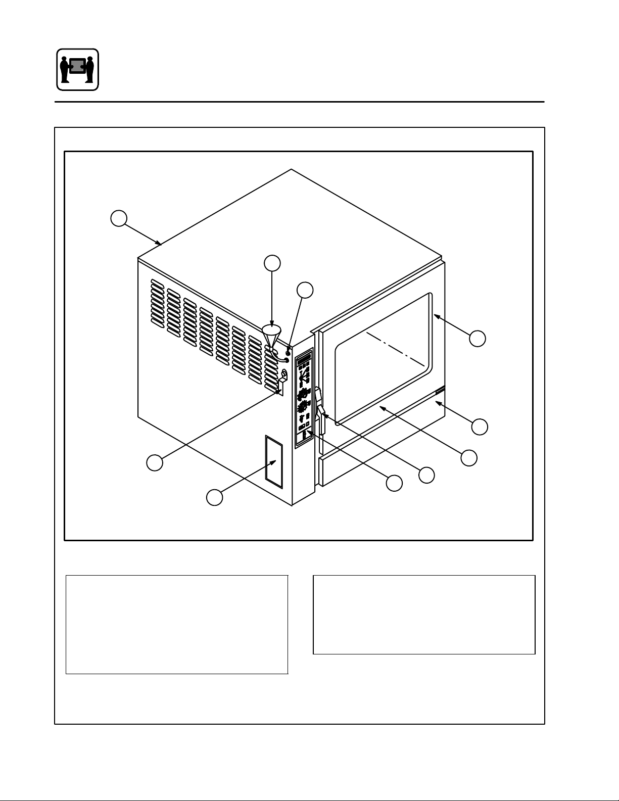
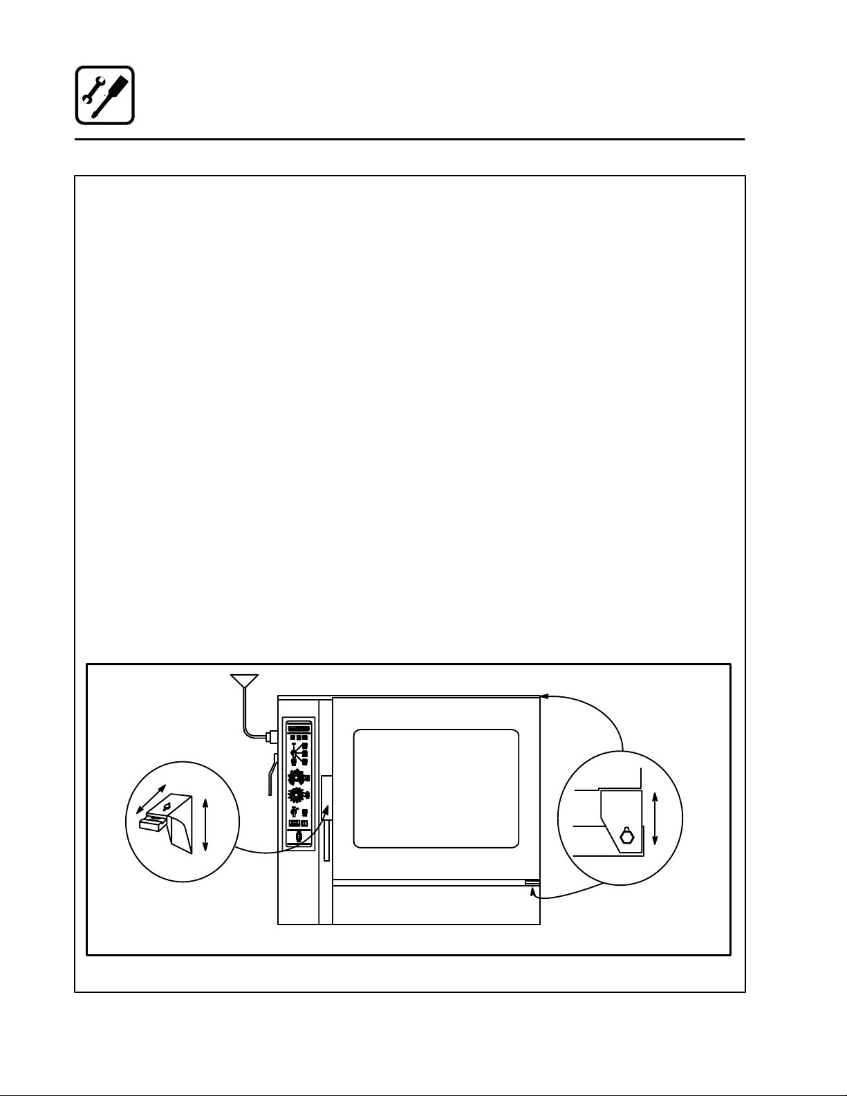
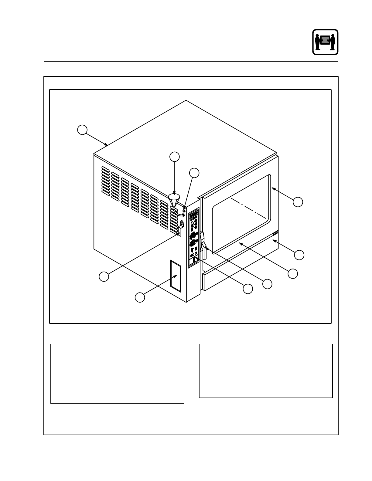
Oven Features
5
Standard Features
6
9
3
7
1 Control Panel
2 Oven Door
3 DripĂCollectorĂ(self draining)
4 Door Handle
5 VentĂ(not shown)
3
2
1
8
COSĆ8E Shown
4
Figure 1
6 Decalcifying Inlet & Funnel Assembly*
7 Decalcifying Valve Lever*
8 Fuses, Power Supply
9 Tilt Down Panel Screw
* only on COSĆ8E and BCSĆ8E
4
Page 9
Installation
y
Owner's Responsibilities
1. Oven(s) are uncrated, stacked (if applies) and
put in place.
NOTE: Refer to Leg Attachment and Stacking
information provided.
2. The owner/operator must have the following
plumbing and electrical requirements met and
installed.
NOTE: Refer to the Utility Connection inforĆ
mation provided.
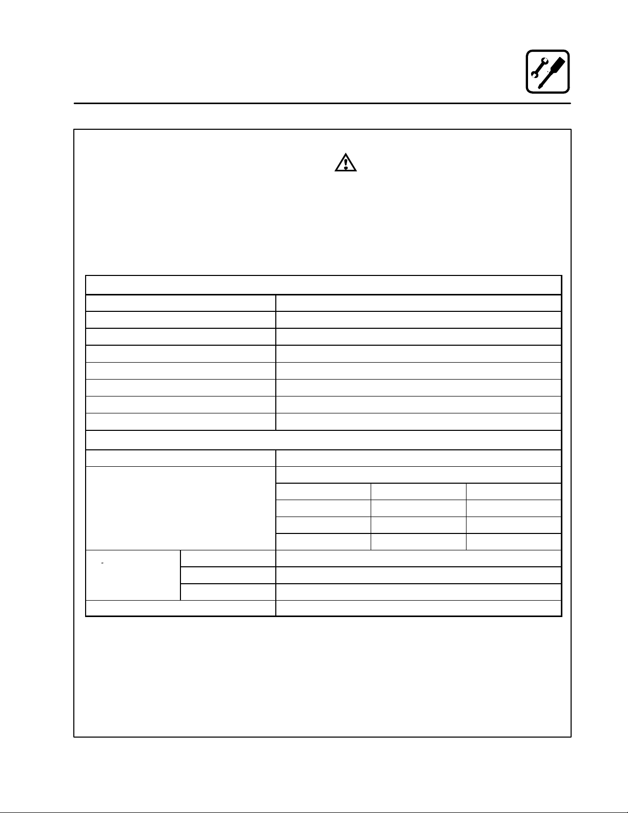
PLUMBING
Water
Building Water Pressure (min/max) 40 PSI min/50 PSI max
Cold Water Connection 3/4" Hose Fitting, 3/8" ID hose minimum
Hot Water Connection* 3/4" Hose Fitting*, 3/8" ID hose minimum
Pressure Regulator Setting 35 PSI Preset
Drainage Atmospheric Vented Drain
Drain Connection 2" Copper
Avg Water Drain Temp. 122_F (50_C)
WARNING!!
Improper installation, adjustment, alterĆ
ation service or maintenance can cause
property damage, injury or death. Read
the installation, operation and mainteĆ
nance instruction thoroughly before inĆ
stalling or servicing this equipment.
ELECTRICAL
Electrical* 18.4kw
Volt 3 Phase 1 Phase
208 52 89
240 45 77
480 23 N/A
By Mode
Blower Motor .5 hp / 0.5 kw
*Not applicable with COSĆ8EDS, BCSĆ8DS and CNVĆ8E
Steam 18.5kw
Hot Air 18.5kw
Combi 18.5kw
Amp/Line (max)
5
Page 10

Location
Installation
The well planned and proper placement of your
appliance will result in long term operator conveĆ
nience and satisfactory performance.
The following clearances must be maintained beĆ
tween the unit and any combustible or nonĆcomĆ
bustible construction.
D Oven body right side - 4" (10 cm)
D Oven body left side - 4" (10 cm) with casters
12" (30 cm) without
casters
D Oven body back - 4" (10 cm)
NOTE: For models with hose assemblies on the
back of the unit, the hose must be 4" (10
cm) from the wall.
If optional casters are not used, the following
clearances are recommended for service.
D Oven body left side - 12" (30 cm)
D Oven body back - 12" (30 cm)
Place the unit in an area which is free of drafts and
accessible for proper operation and servicing.
Keep the oven area free and clear of all combusĆ
tibles such as paper, cardboard, and flammable
liquids and solvents.
DO NOT place the oven on a curb base or seal to
the wall; either condition will prevent proper ventiĆ
lation to the blower motors. Slight unevenness can
be corrected with the adjustable legs.
Heat sources must not be located near the air
vents on the left hand side of the unit. Consult the
factory for an optional protective side heat shield
kit if a warm surface or water source is to the left
of the unit. If excessive ambient temperature or a
water source is present a heat shield must be addĆ
ed to the left hand side of the oven to protect the
unit from excessive heat or water
D COSĆ8E heat shield P/N R9048
D COSĆ8EDS heat shield P/N R9048
D BCSĆ8E heat shield P/N R9048
D BCSĆ8DS heat sheild P/N R9048
D CNVĆ8E heat shield P/N R9048
On all models, tripping the blower motor's thermal
overload device indicates an excessive ambient
temperature at the side of the oven. This must be
corrected to prevent permanent damage to the
oven. All motor bearings are permanently lubriĆ
cated by the manufacturer; there is no need for
additional lubrication during the operational lifeĆ
time of the motors.
6
Page 11
Installation
Agency Approvals
THE INSTALLATION INSTRUCTIONS CONĆ
TAINED HEREIN ARE FOR THE USE OF QUALIĆ
FIED INSTALLATION AND SERVICE PERSONNEL
ONLY. INSTALLATION OR SERVICE BY OTHER
THAN QUALIFIED PERSONNEL MAY RESULT IN
DAMAGE TO THE OVEN AND/OR INJURY TO
THE OPERATOR.
Qualified installation personnel are individuals, a
firm, a corporation, or a company which either in
person or through a representative are engaged
in, and are responsible for:
D The installation of electrical wiring from the elecĆ
tric meter, main control box or service outlet to
the electric appliance.
Qualified installation personnel must be experiĆ
enced in such work, be familiar with all precauĆ
tions required and have complied with all requireĆ
ments of state or local authorities having
jurisdiction.
U.S. and Canadian Installations
Reference: National Electrical Code, ANSI/NFPA
70-Latest Edition and/or Canadian Electrical
Code CSA C22.1 as applicable.
This equipment is to be installed in compliance
with the Basic Plumbing Code of the Building OffiĆ
cials and Code Administrators International Inc.
(BOCA) and the Food Service Sanitation Manual of
the Food and Drug Administration (FDA).
General Export Installations
Installation must conform with Local and National
installation standards. Local installation codes
and/or requirements may vary. If you have any
questions regarding the proper installation and/or
operation of your unit, please contact your local
distributor. If you do not have a local distributor,
please call Blodgett Combi at 0011Ć802Ć860Ć3700.
7
Page 12
Installation
Utility Connections
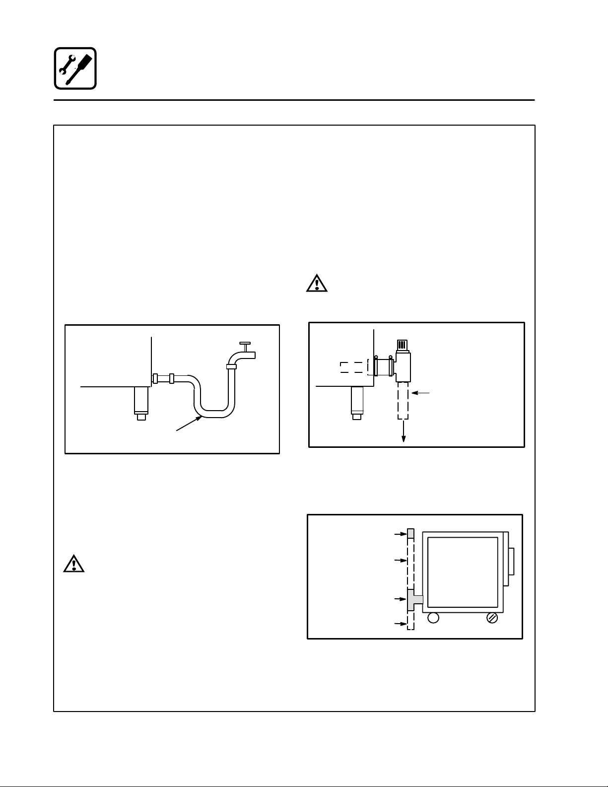
HOT AND COLD WATER CONNECTION
NOTE: Hot water maximizes steam production,
but is not required. Cold water may be supĆ
plied to both inlets if hot water is not availĆ
able. Hot water must not be applied to the
cold water inlet.
COSĆ8E and BCSĆ8E - Connect cold water hose
to the cold water (left) solenoid and hot water to
the hot water (right) solenoid. Use pressure hose
with 3/4" (1.9 cm) fittings and wall shut off valves
for service.
COSĆ8EDS, BCSĆ8DS and CNVĆ8E - Connect
the units to quality cold water via a pressure hose
with 3/4" (1.9 cm) couplings.
1/2" Appliance Hose
With 3/4" Hose Fittings
Figure 2
Water must meet the following minimum requireĆ
ments:
D Total Dissolved Solids (TDS) content will not exĆ
ceed 30 parts per million.
D Water PH must be 7.0 or higher
DRAIN CONNECTION
NOTE: Not applicable for CNVĆ8E convection oven.
A 2" (5 cm) copper pipe with standard drain pitch,
must be run to an open drain or connected to a
standpipe equipped with a vent.
NOTE: The waste water can also be directed to a
nearby floor drain. Flexible hose which alĆ
lows trapped water to accumulate in
sagged runs must be avoided.
WARNING!!
Failure to install the drain kit provided will
invalidate your warranty.
2" (5 cm) Drain
(Customer Supplied)
To Drain
Figure 3
A 24" (61 cm) long standpipe must be connected
to the DWV. This allows the escaping water vapor
to exit above the inlet louvers on the back panel.
Breather Vent
WARNING!!
The use of poor quality water will invaliĆ
date your warranty.
Plumber Installed
Connection
Tee, Hose and Clamps
Plumber Installed
Connection To Drain
Figure 4
8
Page 13
Installation
Utility Connections
STEAM CONNECTION
NOTE: COSĆ8EDS and BCSĆ8DS only.
Connect the appliance to a 200 psi maximum exĆ
ternal steam source per local or state codes. The
steam must be clean, potable and fit for human
consumption. Failure to connect this appliance to
a suitable steam source will revoke the approval of
NSF.
The appliance is equipped with an internal steam
pressure regulator set at 2 psi. Verify the regulator
is set to 2 psi prior to operating the appliance.
ELECTRICAL CONNECTION
Before making any electrical connections to these
units, check that the power supply is adequate for
the voltage, amperage, and phase requirements
stated on the rating name plate mounted on the
unit.
Wiring diagrams are located on the inside of the
louvered side panel.
NOTE: DISCONNECT THE POWER SUPPLY TO
THE UNIT BEFORE SERVICING!
U.S. and Canadian installation
All units, when installed, must be electrically
grounded in accordance with local codes or in the
absence of local codes, with the National Electrical
Code, ANSI/NFPA 70-Latest Edition and/or CanaĆ
dian Electrical Code CSA C22.1 as applicable.
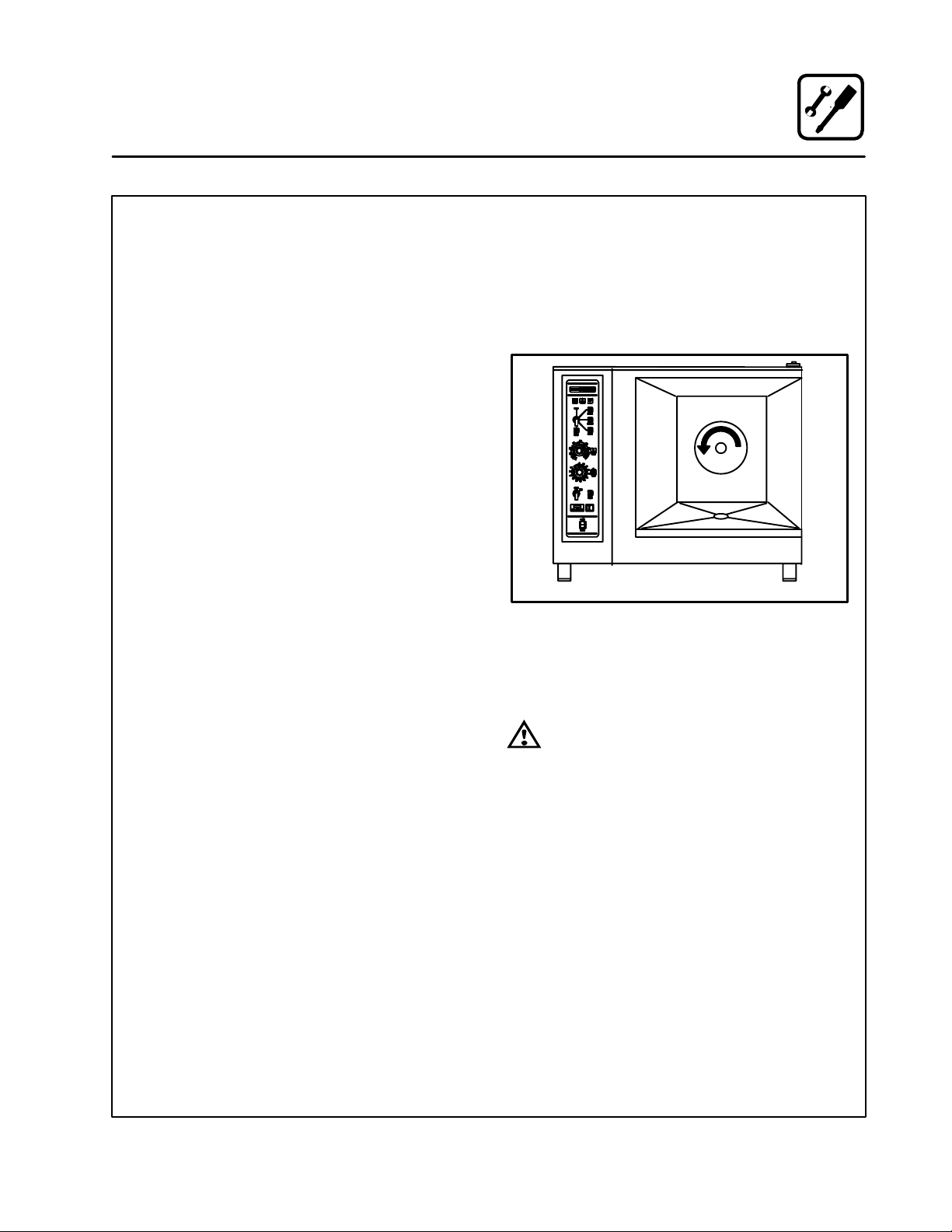
General Export Installations
CAUTION: on 480V units, the fan should be
checked to ensure the proper rotation after
connecting the appliance. See Figure 5. If the
fan turns in the wrong direction, the appliance
will not function properly and damage to the
unit can occur. Improper connection of the apĆ
pliance renders the warranty invalid.
Direction Of Fan Rotation
Figure 5
NOTE: ALL MANUAL RESETS SHOULD BE REĆ
STORED BEFORE CONNECTING POWER
TO THE APPLIANCE.
WARNING!!
Improper electrical installation will invaliĆ
date your warranty.
Installation must conform with Local and National
installation standards. Local installation codes
and/or requirements may vary. If you have any
questions regarding the proper installation and/or
operation of your unit, please contact your local
distributor. If you do not have a local distributor,
please call Blodgett Combi at 0011Ć802Ć860Ć3700.
9
Page 14
Installation
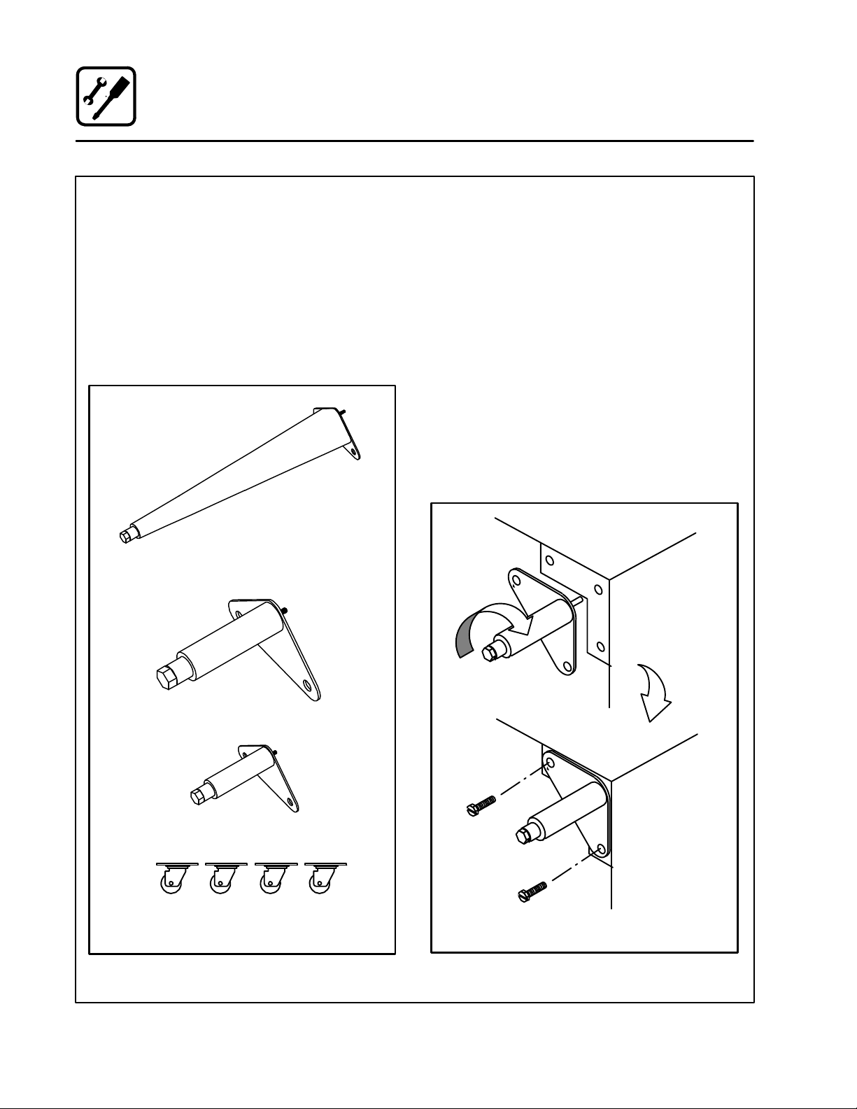
Optional Leg Attachment
LEG OPTIONS
Legs are available in 4" (10 cm), 6" (15 cm) āor ā25"
ā(64 cm) ālengths āāor āālow profile casters. The 6" legs
can be used on the lower section of a double
stacked unit. The 4" legs may be used with the opĆ
tional stands if additional height is required or
when mounting on a counter. The 25" legs are
used for a single oven located on the floor.
NOTE: For safety reasons, casters must not be
used with the 25" ā(64 cm) legs.
25I Adjustable Leg
LEG ATTACHMENT
NOTE: If low profile casters are used, install the
locking casters on the front of the oven.
The rear casters do not lock. Be sure the
locks are set on the front casters.
1. Align the threaded stud the each leg to the bolt
āholesā locatedāāā ināā ātheā āāunit'sā bottom ācorners.
Turn the legs clockwise and tighten to the
nearest full turn.
2. Align the leg plate holes with the bolt holes.
Secure with the two 1/2" bolts provided.
3. Tip the oven up on the legs. If ācastersā are
āused, checkā thatā the locksā areā setā on ātheā front
casters.
4. Except for units with casters, level the oven by
screwing the adjustable feet in or out as necĆ
essary.
6I Adjustable Leg
4I Leg
Low Profile Casters
Figure 6
6" (15 cm) Legs Shown
Figure 7
10
Page 15
Installation
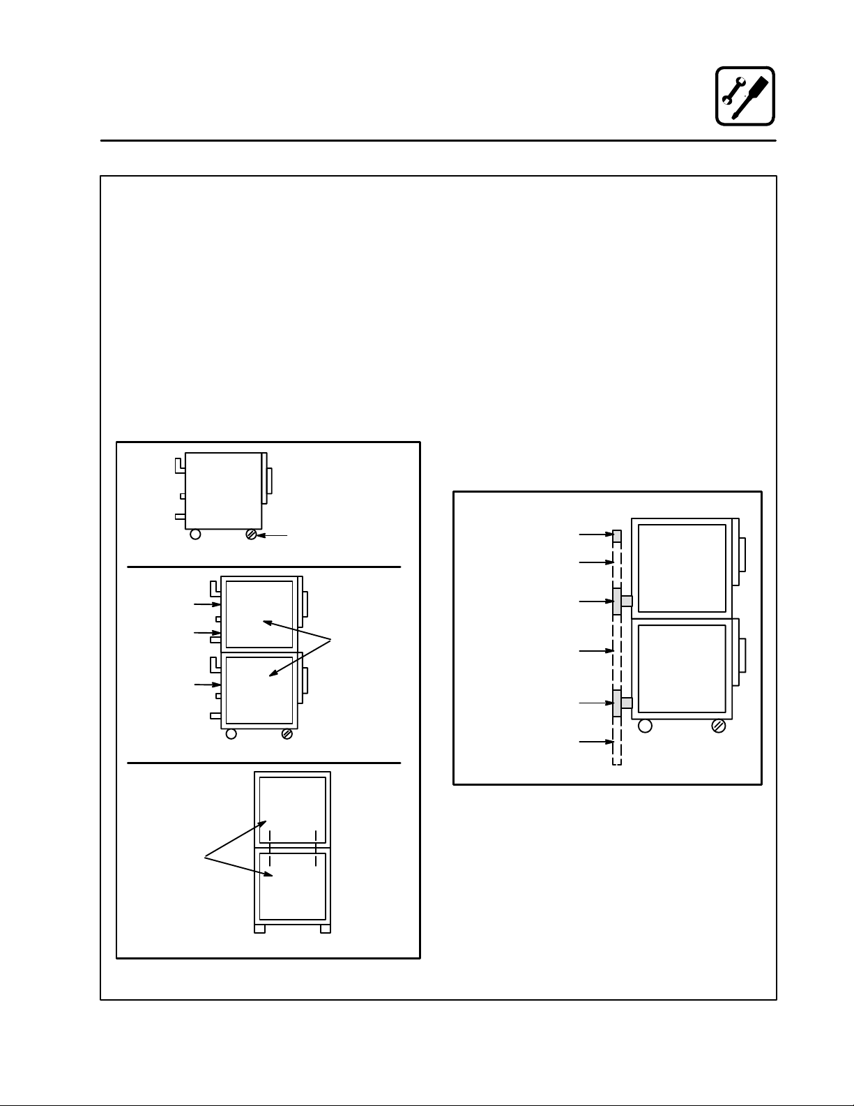
Stacking
STACKING
1. Install 6" (15 cm) legs or casters on the bottom
unit. If casters are used, the casters with
brakes must be located on the front of the
oven.
2. Remove the three screws from the top of the
bottom unit.
3. Lift and mount the upper unit onto the lower
unit. Flush the edges on all four sides. Remove
the side panel and body back of both units.
Remove the lower body back from the top
unit.
4. Bolt the upper and lower units together with
the .50Ć13 UNC bolts provided.
Do Not Remove
Body Top
Caster with brakes
Step 1
Remove
body back
Remove
lower body
back
Remove
body back
Remove
louvered
panel and
save screws
PLUMBING
NOTE: When stacking a CNVĆ8E with a COSĆ8E,
COSĆ8EDS or BCSĆ8E the drains must not
be manifolded together.
NOTE: The installation plumber is responsible for
connections between units and connecĆ
tion to the drain. Use a 24" section on the
top unit Tee to raise the breather vent. This
will prevent overflow if both units are flushĆ
ing simultaneously.
1. Attach the rubber couplings (included) to the
drain outlet of both units.
2. Install 2" copper pipe (not included) to the
floor drain.
3. Install suitable tubing to the floor drain from
the drip pan outlet on the rear of the unit.
Breather vent
Plumber installed
connection 24" long
Rubber coupling
Plumber installed
connection
Rubber coupling
Bolt through
holes closest
to oven center
Step 3
Step 4
Figure 8
Plumber installed
connection to drain
Figure 9
Rear of Units
11
Page 16
Installation
Final Check and Adjustments
BEFORE SWITCHING THE APPLIANCE ON
Before applying power to the unit for the first time,
check for the following conditions:
j All āelectricalā safety provisions have been adĆ
hered to and the electrical connections are
correct.
j Water is connected, turned on and all of the
connections are water tight.
NOTE: COSĆ8E and BCSĆ8E units only - The
first time the unit is turned on, or after the
unit has been OFF for 5 hours and then
turned on, āit āwill automatically flush the
steam generator for a period of 75 secĆ
onds. The steam generator will then fill to
the proper water level. The unit is now
ready for operation.
DOOR ADJUSTMENT
The door catch may be adjusted in two directions,
in and out, and up and down, using the following
procedure:
1. Adjust catch up and down by loosening the
two boltsā holdingā theā catch to the face of the
unit (A).
2. Make āadjustmentsā soā thatā theā leadingā face of
the catch is centered in the opening of the
handle assembly.
3. Tighten the bolts so that there is no further
movement.
4. Adjust catch in and out by loosening the bolt
on the top of the catch (B).
5. The āāadjustment āāface āāis āstepped āso āthat moveĆ
ment is limited with the bolt tightened properĆ
ly.
6. The āadjustment āis ācorrect āwhen āthe ādoor closes
firmly and no steam leaks from the gasket.
The hinges can also be adjusted as follows:
1. Be certain the catch is adjusted properly.
2. Adjustā hinges āso āthatā the door back and the
unit face are parallel (C).
3. The adjustment is correct when no steam
leaks through the gasket and the door is very
slightly compressing the gasket.
Oven
B
A
Door
COSĆ8E shown
Figure 10
12
C
Page 17
Installation
Final Check Lists
ELECTRICAL CONTROL COMPARTMENT
Applied voltage to unit voltage/phase suitable for
appliance specified.
j Remove side panel
j Adjust motor protector to maximum (480V only)
j Reset high limit thermostats
j Check fuses
j Reinstall side panel
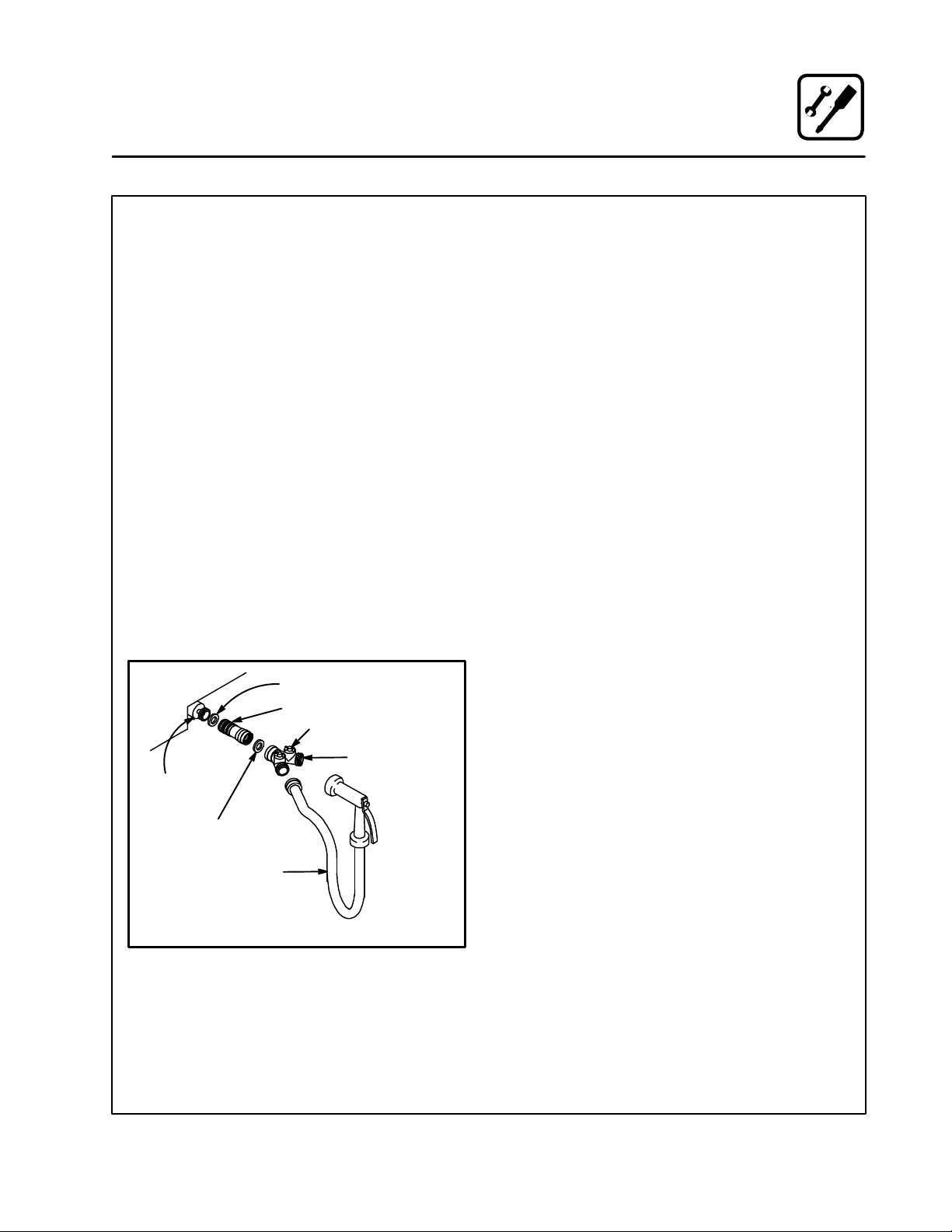
PLUMBING FINAL CHECK
j Incoming water pressure within 40 PSI (miniĆ
mum) Ć 50 PSI (maximum)
j Water solenoids are properly bracketed and
not leaking
j 24" atmospheric standpipe vent/drain properĆ
ly installed
j Water feed lines intact without leaks
j Water pressure regulators installed
j Spray hose connected properly
Washer
Regulator Assembly
Y" Fitting
Cold water supply
Fill
Solenoid
Washer
OVEN OPERATIONAL TESTS
NOTE: Checks to be made by customer or authoĆ
rized service agent.
Cool Down Mode (if applicable)
j Turn Switch to COOL DOWN position and
verify that the motor operates with the door
open.
Combi Mode (if applicable)
Turn to COMBI mode, set thermostat to 350_F
(177_C) and verify:
j Steam generator flushes and fills
j Steam generator preheats to 175_F (79_C)
then switches to hot air
j When hot air reaches 350_F (177_C) hot air
shuts off and steam comes on
Steam Mode (if applicable)
Remove control panel, turn to STEAM mode and
verify:
j Check timer operation in both positions
1. Set timer in position other than ON, timer
should count down
2. Set timer in ON position, oven should opĆ
erate continuously without timer
j Run light (power light) turns on
j Unit produces steam, window fogs, door seal
does not leak
j Quenching system working
Hose and Spray
Spray Hose Connection
Figure 11
Hot Air Mode (if applicable)
Turn to HOT AIR mode and set thermostat to
400_F (205_C) and verify:
j Heat demand light is on
j Oven is heating properly
j Heat lights shuts off at 400_F (205_C) and
oven maintains 400_F (205_C)
13
Page 18

Operation
Oven StartĆUp
STEAM MODE (if applicable)
NOTE: For direct steam units, skip steps 3-5.
1. Turn the mode selector switch to STEAM.
2. The green POWER Indicator lamp on the front
control panel lights.
3. The steam generator flushes and drain autoĆ
matically for 75 seconds if the unit has been off
for at least 5 hours.
4. The steam generator begins to fill. After two
minutes, the FILL indicator lamp on the front
control panel blinks. The convection blower
and POWER lamp turn off.
5. When the steam generator is filled to the propĆ
er level, the convection blower, interior lights
and POWER indicator lamp turn on.
6. Steam fills the cavity and is controlled by a
nonĆaccessible internal thermostat.
HOT AIR MODE (if applicable)
1. Turn the mode selector switch to Hot Air.
2. The green POWER Indicator lamp on the front
control panel lights.
3. Set the hot air thermostat to the desired temĆ
perature.
4. The thermostat lamp lights, indicating the cavĆ
ity temperature is below the desired set point.
5. When the cavity temperature reaches the deĆ
sired set point, the temperature indicator lamp
goes off. The convection blower continues to
run until the door is opened or the timer preset
time runs out.
COMBI MODE (if applicable)
NOTE: For direct steam units, skip steps 4-6.
1. Turn the mode selector switch to COMBI.
2. The green POWER indicator lamp on the front
control panel lights.
3. Set the Hot Air thermostat to the desired temĆ
perature.
4. The steam generator flushes and drain autoĆ
matically for 75 seconds if the unit has been off
for at least 5 hours.
5. The steam generator begins to fill. After two
minutes the FILL indicator lamp on the front
control panel blinks. The convection blower
and POWER lamp do not shut down.
6. When the steam generator comes up to a preĆ
determined temperature, the hot air thermoĆ
stat lamp illuminates, indicating the cavity
temperature is below the desired set point.
7. When the cavity temperature reaches the deĆ
sired set point, the temperature indicator lamp
goes off.
8. The steam and hot air burners toggle back
and forth responding to the thermostat set
points.
14
Page 19
Operation
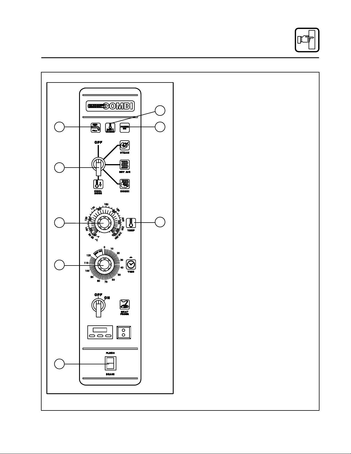
CombiĆOven/Steamer Standard Controls
CONTROLS IDENTIFICATION
1. LOW WATER FILL LIGHT - during the fill
cycle, this light remains on until the water in
2
1
4
7
3
65
the steam generator is at the proper level and
up to temperature. During normal operation the
light should not be on. If the light comes on,
check the water level in the steam generator.
NOTE: COSĆ8EDS, the direct steam unit,
does not have a low water fill light.
2. DON'T STEAM LIGHT - indicates the unit is
too hot to operate in the steam mode. Place
the unit in the Cool Down mode until the temĆ
perature is below 230_F (110_C) and open the
door. This light does not inhibit steam producĆ
tion.
3. POWER ON LIGHT - indicates the unit is in
Steam, Hot Air or Combi.
4. MODE SELECTOR SWITCH - turns power
to the oven on or off. Allows selection of
Steam, Hot Air, Combi or Cool Down Modes.
5. TEMPERATURE DIAL - used to set desired
cooking temperature.
6. HEATING INDICATOR LIGHT - lights when
the Hot Air heating is in operation.
7. TIMER DIAL - used to set desired cooking
time.
8. FLUSH/DRAIN SWITCH - used to flush/
drain the steam generator for decalcification.
NOTE: COSĆ8EDS, the direct steam unit,
does not have a flush/drain switch.
8
COSĆ8E with Meat Probe Shown
Figure 12
15
Page 20

Operation
CombiĆOven/Steamer Standard Controls
OPERATION
1. Turn the MODE SELECTOR Switch (4) to the
desired function.
The POWER ON Light (3) illuminates.
2. Set the TIMER (7) for the desired cooking time
or set it to STAY ON. The buzzer sounds and
the unit shuts off when the time has expired.
3. For the HOT AIR and COMBI modes, set the
TEMPERATURE Dial (5) to the desired cook
temperature. The HEATING INDICATOR Light
(6) illuminates and stays lit until the desired
temperature is reached. The temperature dial
does not operate during the STEAM portion of
the COMBI mode.
4. The selected mode operates automatically.
The temperature, time and mode can be alĆ
tered at any time during the cooking process.
The operation can be stopped by the use of
the Mode Selector Switch or by opening the
door.
5. At the end of the specified time period, the
6. To cool down the oven cavity, switch the
7. The mode selector switch is also the main
buzzer sounds and the appliance shuts off auĆ
tomatically. Move the TIMER (7) to the STAY
ON position to stop the buzzer and restart the
unit.
MODE SELECTOR Switch (4) to COOL
DOWN. In the Cool Down mode neither the
temperature dial or the timer will be operationĆ
al. The blower will function with the door open
or closed.
power switch. In the OFF position the apĆ
pliance is not operational.
16
Page 21

10
11
13
15
18
Operation
Optional CombiĆOven/Steamer Cook & Hold
CONTROLS IDENTIFICATION
1. LOW WATER FILL LIGHT - during the fill
cycle, this light remains on until the water in
the steam generator is at the proper level and
2
1
4
5
7
8
COSĆ8E Shown
3
6
9
12
14
16
17
up to temperature. During normal operation the
light should not be on. If the light comes on,
check the water level in the steam generator.
NOTE: COSĆ8EDS, the direct steam unit,
does not have a low water fill light.
2. DON'T STEAM LIGHT - when lit indicates
the unit is too hot to operate in the steam
mode.
3. POWER ON LIGHT - when lit indicates powĆ
er to the unit is turned on.
4. MODE SELECTOR SWITCH - controls powĆ
er to the oven and selection of steam, hot air
and combi modes. The convection fan runs
with the switch in steam, hot air, combi or cool
down.
5. TIME DISPLAY - gives cook time.
6. TIME ARROW KEYS - press to enter cook
time from 00:00 to 99:59.
7. TEMPERATURE DISPLAY - gives cook temĆ
perature.
8. HEAT LIGHT - when lit indicates hot air or
steam is in operation.
9. TEMPERATURE ARROW KEYS - press to
enter cook temperature from 120-212_F
(48-100_C) for steam and 140-500_F
(60-260_C) for hot air/combi.
10. STAGE ONE LED - when lit indicates operaĆ
tion or programming of stage one for the curĆ
rent product. Cook cycles may contain one or
two different stages.
11. ACTUAL TEMP KEY - press to display actual
oven/steamer temperature
12. STAGE TWO KEY - press to enter stage two
cook time and temperature.
13. PRODUCT KEYS - three programmable keys.
14. MANUAL PRODUCT KEY - default product
key used for manual and programmed cooking.
15. START KEY - press to begin a cook cycle.
16. STOP KEY - press to silence audible alarms
and pause or cancel cook cycles.
Figure 13
17
Page 22

Operation
Optional CombiĆOven/Steamer Cook & Hold
17. PROGRAM KEY - press to enter programĆ
ming mode and save programmed settings.
18. FLUSH/DRAIN SWITCH - Used to flush/
drain the steam generator for decalcification.
NOTE: COSĆ8EDS, the direct steam unit,
does not have a flush/drain switch.
MANUAL OPERATION
1. Turn the SELECTOR SWITCH (4) to the deĆ
sired mode. The LED above the manual key
lights.
2. Press the TEMPERATURE ARROW KEYS (9)
to set the stage one cook temperature.
3. Press the TIME ARROW KEYS (6) to set the
stage one cook time.
4. Press the STAGE TWO KEY (12).
NOTE: Stage two can be used for either a
hold mode or a second cook temperaĆ
ture. Example: Cook meats or poultry
at a low temperature for maximum
moisture retention, then set the secĆ
ond stage for browning. To use the
second stage for holding, you must
set an appropriate hold time for the
unit to count down from.
NOTE: If stage two is not required enter a
cook time of 00:00.
5. Press the TEMPERATURE ARROW KEYS (9)
to set the stage two cook temperature.
6. Press the TIME ARROW KEYS (6) to set the
stage two cook time.
7. Press the START KEY (15) to begin the cook
cycle. The STAGE ONE LED (10) lights. The
TIME DISPLAY (5) counts down the stage one
cook time.
If stage two is selected an alarm sounds at the
end of stage one. The time display counts
down the stage two cook time.
8. When all cook stages are complete the TIME
DISPLAY (5) flashes 00:00, the TEMPERAĆ
TURE DISPLAY (7) flashes 0 and an audible
alarm sounds. Press the STOP KEY (16) to siĆ
lence the alarm. The control maintains the
stage one cook temperature.
9. Turn the SELECTOR SWITCH (4) to OFF to
shut down the oven/steamer.
NOTE: Time and temperature settings may be
changed at any time during manual operaĆ
tion. Press the time arrow keys to change
the cook time. Press the temperature arĆ
row keys to change the cook temperature.
PROGRAMMED OPERATION
NOTE: See page 19 for programming instrucĆ
tions.
1. Turn the SELECTOR SWITCH (4) to the deĆ
sired mode.
2. Press the desired PRODUCT KEY (13). The
LED above the selected key lights.
3. Press the START KEY (15) to begin the cook
cycle. The STAGE ONE LED (10) lights. The
TIME DISPLAY (5) counts down the stage one
cook time.
NOTE: Press the STOP KEY (16) once to pause
an active stage one cycle. Press the
START KEY (15) to resume.
NOTE: Press the STOP KEY (16) twice to canĆ
cel an active stage one cycle.
4. An alarm sounds at the end of stage one The
time display counts down the stage two cook
time.
NOTE: Press the STOP KEY (16) once to canĆ
cel an active stage two cycle. Stage
two cycles cannot be paused.
5. When all cook stages are complete, the TIME
DISPLAY (5) flashes 00:00, the TEMPERAĆ
TURE DISPLAY (7) flashes 0 and an audible
alarm sounds. Press the STOP KEY (16) to siĆ
lence the alarm. The control maintains the
stage one cook temperature.
18
Page 23

Operation
Optional CombiĆOven/Steamer Cook & Hold
PROGRAMMING THE PRODUCT KEYS
NOTE: Each product key can hold two programs:
one for steam and one for hot air/combi. Hot
air programs can be used in combi.
1. Turn the SELECTOR SWITCH (4) to the deĆ
sired mode.
2. Press the desired PRODUCT KEY (13).
3. Press and hold the PROGRAM KEY (17) for
five seconds. The control beeps. The product
key LED and STAGE ONE LED (10) light.
4. Press the TEMPERATURE ARROW KEYS (9)
to set the stage one cook temperature.
5. Press the TIME ARROW KEYS (6) to set the
stage one cook time.
6. Press the STAGE TWO KEY (12).
NOTE: Stage two can be used for either a
hold mode or a second cook temperaĆ
ture. Example: Cook meats or poultry
at a low temperature for maximum
moisture retention, then set the secĆ
ond stage for browning. To use the
second stage for holding, you must
set an appropriate hold time for the
unit to count down from.
NOTE: If stage two is not required enter a
cook time of 00:00.
7. Press the TEMPERATURE ARROW KEYS (9)
to set the stage two cook temperature.
8. Press the TIME ARROW KEYS (6) to set the
stage two cook time.
9. Press and hold the PROGRAM KEY (17) to
save the program settings.
PROGRAMMING THE MANUAL KEY
NOTE: The manual key may be used for manual
cooking and programmed for two prodĆ
ucts, one for steam and one for hot air/comĆ
bi. Hot air programs can be used in combi.
1. Turn the SELECTOR SWITCH (4) to the deĆ
sired mode.
2. Press the MANUAL KEY (14). The LED above
the manual key lights.
3. Press the TEMPERATURE ARROW KEYS (9)
to set the stage one cook temperature.
4. Press the TIME ARROW KEYS (6) to set the
stage one cook time.
5. Press the STAGE TWO KEY (12).
NOTE: Stage two can be used for either a
hold mode or a second cook temperaĆ
ture. Example: Cook meats or poultry
at a low temperature for maximum
moisture retention, then set the secĆ
ond stage for browning. To use the
second stage for holding, you must
set an appropriate hold time for the
unit to count down from.
NOTE: If stage two is not required enter a
cook time of 00:00.
6. Press the TEMPERATURE ARROW KEYS (9)
to set the stage two cook temperature.
7. Press the TIME ARROW KEYS (6) to set the
stage two cook time.
8. Press and hold the PROGRAM KEY (17) to
save the program settings.
NOTE: Time and temperature settings may be
changed at any time during operation of a
programmed manual key. Press the time
arrow keys to change the cook time. Press
the temperature arrow keys to change the
cook temperature.
19
Page 24
Operation
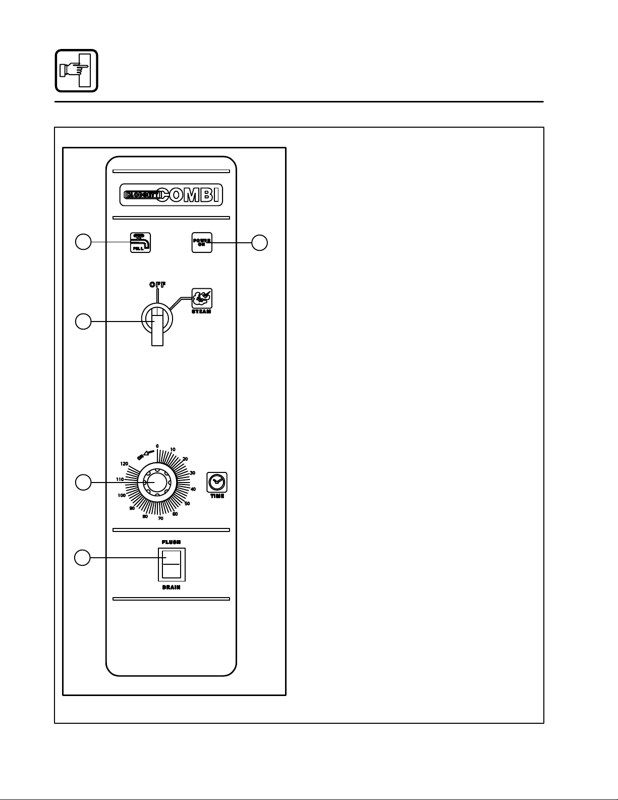
Convection Steamer Standard Controls
1
3
2
CONTROLS IDENTIFICATION
1. LOW WATER FILL LIGHT - during the fill
cycle, this light remains on until the water in
the steam generator is at the proper level and
up to temperature. During normal operation the
light should not be on. If the light comes on,
check the water level in the steam generator.
NOTE: The BCSĆ8DS direct steam unit does
not have a low water fill light
2. POWER ON LIGHT - when lit indicates powĆ
er to the unit is turned on.
3. MODE SELECTOR SWITCH - turns power
to the steamer on or off.
4. TIMER DIAL - used to set desired steam time.
5. FLUSH/DRAIN SWITCH - used to flush/
drain the steam generator during decalcificaĆ
tion.
NOTE: The BCSĆ8DS direct steam unit does
not have a flush/drain switch.
OPERATION
NOTE: Before the first use of the appliance, daily
or after the unit has been idle for 5 hours,
preheat with the STEAM function approxiĆ
mately 1Ć2 minutes.
1. Turn the SELECTOR SWITCH (3) to STEAM.
4
5
BCSĆ8E shown
2. Set āthe āTIMER ā(4)ā āfor ātheā desiredāā steam ātimeā
or set āit to STAYā āON. āThe āāābuzzer āāsounds āand
ātheā unitā āāshutsā off when the time has expired.
3. At āthe āend āof āthe āspecified time period, the
buzzer sounds andā theā appliance āshutās āāoff auĆ
tomatically.āā Move āāthe TIMER ā(4) to āthe āSTAYā
ONā position toāā stop the buzzer and restart the
unit.
4. Theā Mode Selector Switch is also the main
power switch. In the OFF position the
appliance is not operational.
Figure 14
20
Page 25

CONTROLS IDENTIFICATION
1. POWER ON LIGHT - when lit indicates powĆ
er to the unit is turned on.
2. SELECTOR SWITCH - allows selection of
Hot Air or Cool Down Mode.
3. TEMPERATURE DIAL - used to set desired
cooking temperature.
4. HEATING INDICATOR LIGHT - lights when
the Hot Air heating is in operation.
5. TIMER DIAL - used to set desired cook time.
Operation
Convection Oven Standard Controls
1
OPERATION
1. Turn the SELECTOR switch (2) to HOT AIR.
2. Load product into the oven when ready.
3. Turn the TEMPERATURE DIAL (3) to the deĆ
sired temperature.
4. Turn the TIMER DIAL (7) to the desired cook
time.
5. At the end of the specified time period, the
buzzer sounds and the appliance shuts off auĆ
tomatically. Move the timer to the STAY ON
position to stop the buzzer and restart the unit.
6. Turn the SELECTOR switch (2) to the COOLĆ
DOWN position.
2
3
5
4
21
Figure 15
Page 26

Operation
Optional Convection Oven Cook and Hold
CONTROLS IDENTIFICATION
1. POWER ON LIGHT - when lit indicates powĆ
2. MODE SELECTOR SWITCH - controls powĆ
1
3. TIME DISPLAY - gives cook time.
4. TIME ARROW KEYS - press to enter cook
2
3
5
6
8
9
11
13
4
7
10
12
14
15
5. TEMPERATURE DISPLAY - gives cook temĆ
6. HEAT LIGHT - when lit indicates hot air is in
7. TEMPERATURE ARROW KEYS - press to
8. STAGE ONE LED - when lit indicates operaĆ
9. ACTUAL TEMP KEY - press to display actual
10. STAGE TWO KEY - press to enter stage two
11. PRODUCT KEYS - three programmable
12. MANUAL PRODUCT KEY - default product
13. START KEY - press to begin a cook cycle.
14. STOP KEY - press to silence audible alarms
15. PROGRAM KEY - press to enter programĆ
er to the unit is turned on.
er to the oven and selection of hot air and cool
down modes. The convection fan runs with
the switch in hot air or cool down.
time from 00:00 to 99:59.
perature.
operation.
enter cook temperature from 140-500_F
(60-260_C).
tion or programming of stage one for the curĆ
rent product. Cook cycles may contain one or
two different stages.
oven temperature
cook time and temperature.
keys.
key used for manual and programmed cookĆ
ing.
and pause or cancel cook cycles.
ming mode and save programmed settings.
Figure 16
22
Page 27

Operation
Optional Convection Oven Cook & Hold
MANUAL OPERATION
1. Turn the SELECTOR SWITCH (4) to HOT AIR.
The LED above the manual key lights.
2. Press the TEMPERATURE ARROW KEYS (9)
to set the stage one cook temperature.
3. Press the TIME ARROW KEYS (6) to set the
stage one cook time.
4. Press the STAGE TWO KEY (12).
NOTE: Stage two can be used for either a
hold mode or a second cook temperaĆ
ture. Example: Cook meats or poultry
at a low temperature for maximum
moisture retention, then set the secĆ
ond stage for browning. To use the
second stage for holding, you must
set an appropriate hold time for the
unit to count down from.
NOTE: If stage two is not required enter a
cook time of 00:00.
5. Press the TEMPERATURE ARROW KEYS (9)
to set the stage two cook temperature.
6. Press the TIME ARROW KEYS (6) to set the
stage two cook time.
7. Press the START KEY (15) to begin the cook
cycle. The STAGE ONE LED (10) lights. The
TIME DISPLAY (5) counts down the stage one
cook time.
If stage two is selected an alarm sounds at the
end of stage one. The time display counts
down the stage two cook time.
8. When all cook stages are complete the TIME
DISPLAY (5) flashes 00:00, the TEMPERAĆ
TURE DISPLAY (7) flashes 0 and an audible
alarm sounds. Press the STOP KEY (16) to siĆ
lence the alarm. The control maintains the
stage one cook temperature.
9. Turn the SELECTOR SWITCH (4) to OFF to
shut down the oven.
NOTE: Time and temperature settings may be
changed at any time during manual operaĆ
tion. Press the time arrow keys to change
the cook time. Press the temperature arĆ
row keys to change the cook temperature.
PROGRAMMED OPERATION
NOTE: See page 24 for programming instructions.
1. Turn the SELECTOR SWITCH (4) to HOT AIR.
2. Press the desired PRODUCT KEY (13). The
LED above the selected key lights.
3. Press the START KEY (15) to begin the cook
cycle. The STAGE ONE LED (10) lights. The
TIME DISPLAY (5) counts down the stage one
cook time.
NOTE: Press the STOP KEY (16) once to pause
an active stage one cycle. Press the
START KEY (15) to resume.
NOTE: Press the STOP KEY (16) twice to canĆ
cel an active stage one cycle.
4. An alarm sounds at the end of stage one The
time display counts down the stage two cook
time.
NOTE: Press the STOP KEY (16) once to canĆ
cel an active stage two cycle. Stage
two cycles cannot be paused.
5. When all cook stages are complete, the TIME
DISPLAY (5) flashes 00:00, the TEMPERAĆ
TURE DISPLAY (7) flashes 0 and an audible
alarm sounds. Press the STOP KEY (16) to siĆ
lence the alarm. The control maintains the
stage one cook temperature.
23
Page 28

Operation
Optional Convection Oven Cook & Hold
PROGRAMMING THE PRODUCT KEYS
1. Turn the SELECTOR SWITCH (4) to HOT AIR.
2. Press the desired PRODUCT KEY (13).
3. Press and hold the PROGRAM KEY (17) for
five seconds. The control beeps. The product
key LED and STAGE ONE LED (10) light.
4. Press the TEMPERATURE ARROW KEYS (9)
to set the stage one cook temperature.
5. Press the TIME ARROW KEYS (6) to set the
stage one cook time.
6. Press the STAGE TWO KEY (12).
NOTE: Stage two can be used for either a
hold mode or a second cook temperaĆ
ture. Example: Cook meats or poultry
at a low temperature for maximum
moisture retention, then set the secĆ
ond stage for browning. To use the
second stage for holding, you must
set an appropriate hold time for the
unit to count down from.
NOTE: If stage two is not required enter a
cook time of 00:00.
7. Press the TEMPERATURE ARROW KEYS (9)
to set the stage two cook temperature.
8. Press the TIME ARROW KEYS (6) to set the
stage two cook time.
9. Press and hold the PROGRAM KEY (17) to
save the program settings.
PROGRAMMING THE MANUAL KEY
NOTE: The manual key may be used for manual
and programmed cooking.
1. Turn the SELECTOR SWITCH (4) to HOT AIR.
2. Press the MANUAL KEY (14). The LED above
the manual key lights.
3. Press the TEMPERATURE ARROW KEYS (9)
to set the stage one cook temperature.
4. Press the TIME ARROW KEYS (6) to set the
stage one cook time.
5. Press the STAGE TWO KEY (12).
NOTE: Stage two can be used for either a
hold mode or a second cook temperaĆ
ture. Example: Cook meats or poultry
at a low temperature for maximum
moisture retention, then set the secĆ
ond stage for browning. To use the
second stage for holding, you must
set an appropriate hold time for the
unit to count down from.
NOTE: If stage two is not required enter a
cook time of 00:00.
6. Press the TEMPERATURE ARROW KEYS (9)
to set the stage two cook temperature.
7. Press the TIME ARROW KEYS (6) to set the
stage two cook time.
8. Press and hold the PROGRAM KEY (17) to
save the program settings.
NOTE: Time and temperature settings may be
changed at any time during operation of a
programmed manual key. Press the time
arrow keys to change the cook time. Press
the temperature arrow keys to change the
cook temperature.
24
Page 29

Operation
Optional Meat Probe
NOTE: The meat probe is not available for the
Combi Convection Steamer.
CONTROLS IDENTIFICATION
1. MEAT PROBE SWITCH
Controls power to the meat probe.
2. MEAT PROBE CONTROL
Use to set the desired probe temperature. InĆ
dicates the actual temperature of the product
3. MEAT PROBE CONNECTOR
Receptacle for the plug in meat probe.
NOTE: For sanitation it is recommended that
the meat probe remain plugged into
the front panel receptacle at all times.
OPERATION
Measuring the product core temperatures during
long roasting periods is very practical. It is espeĆ
cially important for products such as Roast Beef to
reach a specific internal temperture.
Place the probe through to the middle of the prodĆ
uct's thickest section. Be sure the probe does not
touch any bone and the tip is not in a fat pocket.
These conditions can cause inaccurate readings.
1. Set the MODE SELECTOR Switch to the deĆ
sired function.
2. Turn the MEAT PROBE Switch (1) to ON.
3. To set the desired core temperature press the
blue SET BUTTON (4) on the MEAT PROBE
CONTROL (2).
Use the up arrow key (6) to increase the setĆ
point temperature. Use the down arrow key
(5) to decrease the setpoint temperature.
Press the set button again to store the setĆ
point.
4. Set the TIMER to STAY ON. The cooking proĆ
cess runs automatically.
When the selected core temperature is
reached, the buzzer will sound and the apĆ
pliance shuts off automatically.
The temperature and mode can by changed
at any time during the process.
5. Shut the appliance off by setting the mode
switch to OFF.
NOTE: When setting the internal temperature, be
sure to allow for carryĆover cooking after
the roast is removed from the oven
1
2
3
Figure 17
25
WATLOW
1
2
RDY
SET
4 5 6
Page 30
Maintenance
Spray Bottle Operating Procedure
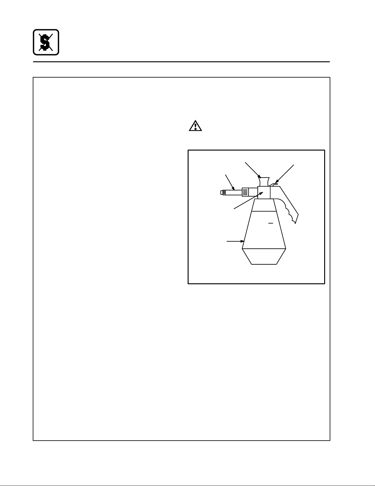
1. Unscrewāā ātheā āāsprayerāāā āhead āāāāandāāā āfillā āāāthe containĆ
er to the MAX mark. Screw the head assembly
āon āfirmlyā toā āensureā āan āāairtight seal. The liquid
must be clean and free from foreign matter. Do
not overfill Ć space must be left for compressĆ
ing air.
2. To build up pressure, pump approximately 20
full strokes when the container is filled with liqĆ
uid. The higher the pressure, the finer the
spray. If the container is only partially filled,ā
then āmoreā pumping āāis āārequired āto compress
the additional air space.
3. To spray, depress the trigger with your thumb.
4. After a period of spraying, the pressure will
drop. Restore the pressure by operating the
air pump.
5. Release pressure after use by inverting the
spray head and depressing the trigger or byā
slowly āunscrewing ā theā spray āhead assembly
āwhichā willā allow āairā toā escape āfrom around āāāthe
filling aperture.
6. Afterā use,ā rinse āthe āsprayā bottleā withā clean waĆ
ter and check that the hole in the nozzle is āperĆ
fectly āclean āand clear. Warm water (notā hot)ā
usedā withā aā household ādetergent is a useful
cleaning agent for this purpose.
NOTE: Further information can be found in the inĆ
struction leaflet supplied with your spray
bottle.
Service Parts:
Complete spray bottle P/N R0006
Spray nozzle repair kit P/N R6332
WARNING!!
Protective clothing and eye wear should
be worn while using cleaning agents.
Pressure Pump
Spray Head
Pump
MAX
Pressure
Vessel
Clean the pump 2 or 3 times per week with warm water
Spray Trigger
Figure 18
26
Page 31

Maintenance
Cleaning and Preventive Maintenance
CLEANING THE INTERIOR
Daily cleaning of the appliance is essential for sanĆ
itation and to ensure against operational difficulĆ
ties. Use an oven cleaning detergent in conjuncĆ
tion with the supplied spray bottle.
On stainless interiors, deposits of baked on splatĆ
ter, oil, grease or light discoloration āmay ābe āreĆ
moved āwith āa good non toxic industrial stainless
steel cleaner. Apply cleaners when the unit is cold
and always rub with the grain of the metal. The
racks, rack supports and the blower wheel may be
cleaned either in the unit or removed āand āsoaked
in a solution of ammonia and water.
NOTE: DO NOT use corrosive cleaners!
Oven/Steamers and Convection Steamers
1. Cool āāthe āappliance down to 140_F (60_C) or,
if the āunitāā has āābeenā āidle, āāturnā the steam modeā
onā foār 3 āto ā4ā minutesā inā order āāāto warm the interiĆ
or surfaces.
2. Fill āāāāātheāāā āsprayāāā ābottleā āāandāāā pump āāāairā āāintoāā āthe conĆ
tainer with the pressure pump.
3. Spray āāthe āinteriorā of āātheāā unitā with a cleaning soĆ
lution.
NOTE: Never spray water into the unit when
the temperature is above 212_F.
NOTE: Oven/Steamers - NEVER SPRAY WAĆ
TER IN THE UNIT AFTER USING THE
HOT AIR OR COMBI MODES.
4. Let āthe ācleanerā āworkāā for āā10ā toā 20 minutes withāāāāā
the āāāāunitā āāāāoff.āāā āForā āādifficult cleaning allow to work
over night.
5. Set the timer for 15 to 20 minutes. Turn ātheā
āmodeā āāselector switch to Steam. This will softĆ
en all burned on residue.
6. Rinseāā āāthe interiorā āāāwithāāāāā the hose and spray asĆ
sembly.
7. Setā āāātheā āāāmode āāāselectorāāā toā āāsteam āāāforā anotherā five
minutes to flush out the interior and remove all
detergent residue.
NOTE: The āinterior ācavity ā should ā never ā be
scoured or scraped.
Convection Ovens
1. Cool āāthe āoven down to 140_F (60_C).
2. Fill āāāāātheāāā āsprayāāā ābottleā āāandāāā pump āāāairā āāintoāā āthe conĆ
tainer with the pressure pump.
3. Spray āāthe āinteriorā of āātheāā ovenā with a cleaning
solution.
NOTE: Never spray water into the unit when
the temperature is above 212_F
4. Let āthe ācleanerā āworkāā for āā10ā toā 20 minutes withāāāāā
the āāāāovenā āāāāoff.āāā āForā āādifficult cleaning allow to work
over night.
5. Rinseāā āātheāāā āovenāāāāā interiorā āāāwithāāāāā the hose and
spray assembly.
NOTE: The āinterior ācavity ā should ā never ā be
scoured or scraped.
CLEANING THE EXTERIOR
Exteriors may be cleaned and kept in good condiĆ
tion with a stainless steel polish.
NOTE: DO NOT spray the outside of the appliance
with water.
PREVENTIVE MAINTENANCE
The best preventive maintenance measures are:
D the āāāproper āāinitial āāinstallation āāof āāthe equipment
D deliming the steam generator (if applicable)
D a program for routine cleaning.
These units requires no lubrication. Contact the
factory, a factory representative or a local Blodgett
Combi service company to perform maintenance
and repairs should they be required.
WARNING!!
Disconnect the appliance from the power
supply before servicing or cleaning.
27
Page 32

Maintenance
Decalcification
NOTE: This procedure applies to models COSĆ8E
and BCSĆ8E only.
1. Turn the Mode Selection Switch (1) to the
STEAM mode. Wait until steam is produced.
This will ensure that the water in the steam
generator is hot.
2. Turn the Mode Selection Switch (1) to the
COOL DOWN mode and leave the door open.
Let the oven compartment cool to 150_F
(66_C). This ensures that the Drain/Flush
switch will function in STEP 8.
3. Turn the Mode Selection Switch (1) to OFF.
4. In a suitable size container, mix together the
deliming solution and hot tap water. Refer to
the following chart for the proper mixture:
Deliming
Model
COSĆ8E 30 oz. 2Ć1/2 gallons
BCSĆ8E 30 oz. 2Ć1/2 gallons
NOTE: These volumes are approximate. You
may need slightly more or less hot waĆ
ter depending on your site.
5. Remove the Deliming Port Cap from the DeĆ
liming Inlet (5). Attach the supplied Funnel
and Hose Assembly (3) to the deliming inlet.
6. Open the Deliming Port Valve (2) and pour in
the deliming mixture. Stop pouring when the
funnel stops draining. This is the correct
amount for your site.
Solution Hot Tap Water
7. Shut the Deliming Port Valve (2). Screw on the
Deliming Port Cap. Let the mixture stand for 20
minutes. In areas of the country with hard waĆ
ter, allow the mixture to stand for 1 hour maxiĆ
mum.
8. Depress and hold the Drain/Flush Switch (4)
in the FLUSH position for 90 seconds. This
completes the deliming procedure.
3
2
1
5
open
close
4
Figure 19
28
Page 33

COSĆ8E, COSĆ8EDS, BCSĆ8E, BCSĆ8DS et CNVĆ8E
Appariels de Cuisson D'Électrique
Manuel D'Installation - Fonctionnement - Entretien
29
Page 34

Introduction
La ligne d'appareils de cuisson de Blodgett Combi
Depuis un certain temps le matériel de cuisson
commerciale est resté plus ou moins inchangé. Il
y a des bouilloires, des fours ouverts, des bonnes
vieilles cuisinières avec leurs régiments de casseĆ
roles et de nombreux autres appareils. Le résultat:
gaspillage de temps, excès de travail manuel, et
des processus de nettoyage interminables. Ces
quelques dernières années ont préparées la voie
pour une révolution dans l'équipement des cuiĆ
sines de restaurants et de collectivités. Blodgett
Combi est heureux de vous présenter trois nouĆ
veaux appareils de cuisson, parmi lesquels vous
trouverez certainement votre bonheur. La ligne de
Blodgett Combi comprend les appareils suivants:
D CombiĆconvection/étuve à vapeur Blodgett
D CombiĆfour à convection Blodgett
D CombiĆfour/étuve à vapeur Blodgett
Tous les appareils électroménagers de Blodgett
Combi améliore votre efficacité dans la cuisine
grâce aux éléments suivants :
D productivité augmentée
D une plus grande gamme de choix pour les menus
D un processus de nettoyage simplifié
Le processus de travail est simplifié puisque les
aliments sont préparés sur ou dans des pots et
des plats pour table chaude. La nourriture peut
être cuîte, rangée et transportée dans les mêmes
ustensiles. Des petites quantités d'aliments peuvĆ
ent être traitées efficacement; plats préparés et aliĆ
ments pratiques peuvent être réchauffés en quelĆ
ques minutes.
COMBIĆCONVECTION/ÉTUVE À VAPEUR
BLODGETT
La cuisson à la vapeur est un procédé bien connu
et fréquemment utilisé dans les restaurants et les
cuisines de collectivités. Avec le Combi étuve à vaĆ
peur Blodgett, il est maintenant possible de profitĆ
er des avantages de la cuisson à la vapeur, dont
certains sont le processus de travail est simplifié,
nourritures de haute qualité, et rétention des vitaĆ
mines.
Le Combi étuve à vapeur Blodgett existe en deux
modèles. Chacun d'eux possède un système de
production de vapeur différent.
D Le modéle BCSĆ8E possède un générateur de
vapeur incorporé qui se compose d'un pavillon
d'aspiration, d'un assemblage entonnoir et
d'un levier de soupape pour le détartrage.
D Le modéle BCSĆ8DS est un four à vapeur diĆ
recte, relié à une source de chaleur externe.
COMBIĆFOUR À CONVECTION BLODGETT
La cuisson dans un four à convection diffère de la
cuisson dans un four de cuisine ordinaire en ce
sens que de l'air chaud circule en permanence auĆ
tour de l'aliment cuit, sous l'effet d'un ventilateur
enfermé dans une enceinte spéciale. Le mouveĆ
ment continu de l'air, en éliminant constamment la
couche d'air froid qui se formerait autrement autoĆ
ur de l'aliment, permet la pénétration plus rapide
de la chaleur. Il en résulte un aliment de qualité
comparable à ceux préparés dans un four ordinĆ
aire, mais cuit à température inférieure et en moins
de temps.
30
Page 35

Introduction
La ligne d'appareils de cuisson de Blodgett Combi
COMBIĆFOUR/ÉTUVE À VAPEUR BLODGETT
Avec le FourĆétuve à Vapeur vous avez le choix
entre deux procédés de cuisson: À la vapeur et à
l'air chaud, soit...
D Séparèment
D En combinaison, ou
D En séquence vous pouvez utiliser deux ou trois
fonctions en séquence au cours d'un procesĆ
sus de cuisson. Nous appelons cela CombiĆvaĆ
peur et CombiĆau four.
Pour faciliter le fonctionnement vous pouvez choiĆ
sir entre trois modes:
Vapeur Air Chaud Combi
(Vapeur et
chaud)
En mode Vapeur vous pouvez:
DĂcuire à la vapeur DĂblanchir DĂpocher
DĂdécongeler DĂthermaliser
En mode Air chaud vous pouvez:
DĂrotir DĂcuire au four DĂbraiser
En mode Combinaison vapeur et air chaud vous
pouvez:
DĂdécongeler DĂrotir DĂthermaliser
DĂréchauffer DĂcuire au four DĂsous vide*
DĂapprêter* DĂcuisson et pause*
* avec commandes numériques en option
Le CombiĆfour/étuve à vapeur Blodgett existe en
deux modèles. Chacun d'eux possède un
système de production de vapeur différent.
D Le modéle COSĆ8E possède un générateur de
vapeur incorporé qui se compose d'un pavillon
d'aspiration, d'un assemblage entonnoir et
d'un levier de soupape pour le détartrage.
D Le modéle COSĆ8EDS est un four à vapeur diĆ
recte, relié à une source de chaleur externe.
31
Page 36

Introduction
Description de la ligne d'appareils de cuisson de Blodgett Combi
À PROPOS DE LA LIGNE COMBI
Les appareils du Combi sont des produits de qualĆ
ité, fabriqués avec des aciers inoxydables de haut
grade par une main d'oeuvre de première classe.
L'usage d'une isolation de haute qualité empêche
une radiation thermique excessive et économise
l'énergie.
Des pieds réglables, en option, adaptent facileĆ
ment sur les surfaces légèrement inégales et,
également. En option, des bâtis d'assise au sol
sont conçus pour être utilisés avec tous les
modêles de table.
CombiĆfour/étuve à vapeur Blodgett et
CombiĆconvection/étuve à vapeur Blodgett
Le système de commande à haute performance,
permet de profiter de tous les avantages d'une
étuve à vapeur de haute qualité par le simple
mouvement d'un interrupteur. Une vapeur fraîche
entre dans le four sans pression et circule à haute
vitesse. Ce procédé permet une cuisson rapide et
douce qui assure des nourritures de haute qualité
tout en offrant des méthodes pratiques de travail.
Un système éliminateur breveté garde l'air du l'apĆ
pareil propre. Les exhalaisons sont aspirées hors
de l'appareil, éliminées et sorties par l'intermédiĆ
aire du tube de condensation. Le système d'évaĆ
cuation est efficace dans tous les modes de cuisĆ
son et a pour résultat une meilleure qualité des
aliments sans transfert de goût. Le ventilateur qui
est protégé contre tout contact accidentel avec les
doigts est actionné par un moteur puissant et siĆ
lencieux. Le tube de condensation retire les excès
de vapeur de l'appareil. Condensation et eau perĆ
due qui sont le résultat de la cuisson étuvée et du
nettoyage s'écoulent continuellement.
UTILISATION
La porte du four pratique avec fenêtre a un large
rayon d'ouverture et une poignée qui fonctionne
facilement même avec des mains mouillées ou
graisseuses.
La facilité de fonctionnement est garantie par le
simple arrangement des commandes. Les symĆ
boles graphiques facilitent l'usage du four, même
par des employés de cuisine sans expérience. Les
modes vapeur, air chaud et combi peuvent être
choisis à partir d'un seul commutateur. Le mode
de refroidissement, permet à l'intérieur du four de
se refroidir rapidement que la porte soit ouverte ou
fermée.
Le nettoyage est minimal. L'intérieur est vaporisé
avec une solution de nettoyage pour enlever faĆ
cilement les croutes et les taches. Le four est conĆ
çu pour un entretien facile et il est soudé étanche
ce qui permet de rincer l'intérieur du four avec un
jet d'eau après le processus de nettoyage.
32
Page 37
Introduction
Caractéristiques
Caractéristiques standard
5
6
9
3
7
8
1 Panneau de Commande
2 Porte du four
3 Collecteur d'égouttement (autoĆpurge)
4 Poignée de la porte
5 Ventilation (pas montré)
COSĆ8E Montrer
Figure 1
3
2
1
4
6 Entrée de détartrage et assemblage
entonnoir*
7 Levier de la soupape de détartrage*
8 Fusibles, Connexion électrique
9 Vis du panneau inclinable
* COSĆ8E et BCSĆ8E seulement
33
Page 38

Installation
Responsabilités du propriétaire
1. Les fours sont sortis de leurs caisses d'embalĆ
lage, empilés (le cas échéant) et mis en place.
REMARQUE:Consultez les informations fourĆ
nies dans les sections Fixation
des pieds et Superposition.
2. Le propriétaire/utilisateur doit remplir les conĆ
ditions de plomberie et d'électricité suivantes.
REMARQUE:Consultez les informations fourĆ
nies dans la section BrancheĆ
ments utilitaires.
PLOMBERIE
Eau
Pression de l'eau (min/max) 50 PSI livres par pouce carré (345 kPa) par unité
Provision pour eau froide Raccord de tuyau de 3/4 po, 3/8 po de diamètre intérieur
(d.i) min
Provision pour eau chaude* Raccord de tuyau de 3/4 po, 3/8 po de diamètre intérieur
(d.i) min
Réglage du régulateur de pression 35 psi statique
Drainage Drain mis à l'air libre
Raccordement du drain 2 po en cuivre
Température moyenne de l'eau drainée A peu près 50_C (122_F)
AVERTISSEMENT!!
Une mauvaise installation, un mauvais réĆ
glage, l'apport de modifications inadéquĆ
ates ou un mauvais entretien de cet appaĆ
reil peuvent entraîner l'endommagement
du matériel ainsi que des blessures
graves, voire mortelles. Lisez soigneuseĆ
ment les instructions d'installation, d'utiĆ
lisation et d'entretien avant d'installer ou
de procéder à l'entretien de ces appaĆ
reils.
CARACTÉRISTIQUES ÉLECTRIQUES
d'électrique* 18.4kw
VAC 3f 1f
208 52 89
240 45 77
480 23 N/A
Par Mode
Moteur de Ventilateur .5 hp / 0.5 kw
*Ne s'applique pas aux modèles COSĆ8EDS, BCSĆ8DS et CNVĆ8E
Vapeur 18.5kw
Air Chaud 18.5kw
Combi 18.5kw
34
A/ligne (max.)
Page 39

Installation
Placement
Un emplacement correct et soigneusement prévu
pour l'appareil aura pour résultat, à long terme, une
utilisation pratique et un rendement satisfaisant.
Les espaces de dégagement ciĆdessous doivent
être prévus entre le four et toute construction
combustible ou non.
D Côté droit du four - 10 cm (4 po)
D Côté gauche du four-
10 cm (4 po) avec roulettes
30 cm (12 po) sans roulettes
D Arrière du four - 10 cm (4 po)
REMARQUE:Pour les modèles munis d'assembĆ
lages de tuyaux à l'arrière de l'appaĆ
reil, le tuyau doit se trouver à 6 po (15
cm) du mur.
Si les roulettes en option ne sont pas utilisées, les
dégagements qui suivent sont recommandés lors
de l'entretien.
D Côté gauche du four - 30 cm (12 po)
D Côté droit du four - 30 cm (2 po)
Placer le four dans une zone sans courants d'air
et accessible pour permettre son fonctionnement
et son entretien.
Garder la zone du l'appareil libre et dégagée de
toutes matières combustibles, telles que papiers,
cartons, liquides inflammables et solvants.
NE PLACEZ PAS l'appareil sur un socle courbé, et
ne le fixez pas au mur. Dans ces deux cas, les moĆ
teurs à soufflerie ne pourraient pas être convenĆ
ablement ventilés. Une petite dénivellation peut se
corriger avec les pieds réglables.
Les grilles d'aération situées du côté gauche le
l'appareil doivent être protégées de la chaleur, de
la vapeur et des sources d'eau. Consultez le fabriĆ
cant pour obtenir un bouclier thermique, en opĆ
tion, si la chaleur ou la vapeur ambiante affecte le
côté gauche de l'appareil.
D Bouclier thermique COSĆ8E P/N R9048
D Bouclier thermique COSĆ8EDS P/N R9048
D Bouclier thermique BCSĆ8E P/N R9048
D Bouclier thermique BCSĆ8DS P/N R9048
D Bouclier thermique CNVĆ8E P/N R9048
Sur tous les modèles : le déclenchement du disposiĆ
tif de surcharge thermique des moteurs à soufflerie
indique que la température ambiante à l'arrière du
four est trop élevée. Cette température doit être corĆ
rigée afin d'empêcher que le four ne soit irrémédiĆ
ablement endommagé. Tous les paliers de moteur
sont lubrifiés en permanence à l'usine; ils ne nécesĆ
sitent aucune lubrification supplémentaire pendant
la durée de vie opérationnelle des moteurs.
35
Page 40

Installation
Normes et Codes
LES CONSEILS D'INSTALLATION ET D'ENTREĆ
TIEN CONTENUS DANS CE MANUEL NE
S'ADRESSENT QU'Á UN PERSONNEL QUALIĆ
FIÉ. UN PERSONNEL NON QUALIFIE PEUT SE
BLES SER ET/OU ABÎMER LE FOUR LORS DE
SON INSTALLATION ET/OU SON ENTRETIEN.
Un personnel d'installation qualifié est représenté
soit par des personnes physiques, soit par un soĆ
ciété, une usine, une corporation qui en personne
ou par l'intermédiaire d'un représentant s'engage
à et est responsable de:
D l'installation du câblage électrique reliant le
compteur d'électricité, l'armoire électrique ou la
prise de courant à l'appareil électrique.
Le personnel d'installation qualifié doit être expériĆ
menté dans ce type de travail, s'être familiarisé
avec toutes les précautions requises et respecter
tous les réglements promulgués par les autorités
provinciales ou locales compétentes.
Installations aux ÉtatsĆUnis et au Canada
L'installation doivent être en accord avec les codes
locaux, ou en l'absence de codes locaux, avec le
Code Électrique National (National Electrical Code),
ANSI/NFPA 70-Dernière édition et/or Code ÉlectriĆ
que Canadien CSA C22.2 si applicable.
Cet équipement doit être installé en respectant les
normes du code de base de la plomberie des proĆ
fessionnels du bâtiment américain et du code inĆ
ternational des administrateurs (Basic Plumbing
Code of the Building Officials and Code AdminisĆ
trators International Inc (BOCA),) ainsi que celles
du manuel de l'hygiène de l'industrie de la reĆ
stauration du secrétariat américain aux produits alĆ
imentaires et pharmaceutiques [Food Service SanĆ
itation Manual of the Food and Drug Administration
(FDA)).
Installations des appareils exportés
L'installation doit suivre les normes locales et nationĆ
ales. Les codes d'installation et/ou les exigences
peuvent varier d'une localité à l'autre. Si vous avez
des questions portant sur l'installation et/ou l'utilisaĆ
tion adéquate de votre four Blodgett, veuillez conĆ
tacter votre distributeur local. Si aucun distributeur
local n'est situé dans votre localité, veuillez appeler
Blodgett Combi au 0011Ć802Ć860Ć3700.
36
Page 41

Installation
Branchement Utilitaires
D'EAU FROID ET CHAUD
REMARQUE:L'utilisation d'eau chaude maximise
la production de vapeur, mais elle
n'est pas obligatoire. Les deux enĆ
trées peuvent recevoir de l'eau froide
si l'eau chaude n'est pas disponible.
COSĆ8E et BCSĆ8E - L'eau froide est connectée
à l'électrovanne de régulation de pression
gauche. L'eau chaud est connectée à l'électroĆ
vanne de régulation de pression droit. Connectez
l'appareil à une entrée d'eau avec un tuyau de
pression muni d'un raccord de 3/4 po (1,9 cm).
Une vanne d'isolement doit être installée à côté du
four.
COSĆ8EDS, BCSĆ8DS and CNVĆ8E - Connectez
les appareils à de l'eau froide de qualité avec à un
tuyau de pression muni d'un raccord de 3/4 po.
BRANCHEMENT DU TUBE D'ÉCOULEMENT
REMARQUE:Ce n'est pas applicable por le modèle
CNVĆ8E.
Un tuyau de 5cm avec une pente de vidange stanĆ
dard doit aller jusqu'à un puisard ou être connecté
sur une colonne descendante équipée d'un évent.
REMARQUE:Les eaux perdues peuvent aussi être
dirigées vers un écoulement au sol
proche. Si un tuyau flexible est utilisé,
s'assurer qu'il n'a pas de longueur
pendant où les eaux usées peuvent
s'accumuler.
ATTENTION!
L'usage d'un purgeur sur la conduite sera
cause de refoulement de vidang.
2" (5 cm) Drain
(Customer Supplied)
Tuyau de l'appareil 12,7mm
avec raccords de 19mm
Figure 2
L'eau doit être conforme aux conditions requises
minimum suivantes:
D Total des solides en suspension (TDS) ne doit
pas dépasser 30 parties par million.
D Le pH de l'eau doit être 7,0 ou auĆdessus.
AVERTISSEMENT!!
L'usage d'eau de mauvaise qualité anĆ
nule la garantie.
To Drain
Figure 3
Un conduit de descente de 60 cm (24 po) de lonĆ
gueur doit être branché sur le tuyau d'évacuation.
Ceci permet aux vapeurs d'eau qui se dégagent
de sortir auĆdessus des ouïes qui sont sur le panĆ
neau arrière.
Orifice de Respiration
Branchement installé
par un plombier
T", Tuyau et brides
Branchement sur
écoulement, installé par
un plumbier
Figure 4
37
Page 42

Installation
Branchement Utilitaires
BRANCHEMENT DE LA VAPEUR
REMARQUE:COSĆ8EDS et BCSĆ8DS seulement.
Brancher l'appareil sur une source extérieure de
vapeur de 1375 kPa (200 PSI) maximum, en acĆ
cord avec les codes locaux ou de province. La vaĆ
peur doit être propre, potable, et bonne pour la
consommation alimentaire. Négliger de brancher
cet appareil sur une source de vapeur adéquate
révoquera l'approbation de NSF.
L'appareil est muni d'un régulateur de pression de
vapeur interne réglé à 2 psi. S'assurer que le
régulateur est bien réglé à 2 psi avant de faire
fonctionner l'appareil.
BRANCHEMENT D'ELECTRICITÉ
Avant toutes connexions électriques de ces unités,
vérifier que l'alimentation électrique est adéquate
pour le voltage, l'ampérage et la phase demandés
sur la plaque signalétique du constructeur qui est
montée sur l'unité.
Les diagrammes de câblage sont situés à l'intéĆ
rieur du panneau latéral à ouïes.
REMARQUE:DÉBRANCHER L'APPAREIL DE L'ALĆ
IMENTIATION ÉLECTRIQUE AVANT
LE SERVICE OUR LE NETTOYAGE.
Installations aux ÉtatsĆUnis et au Canada
L'installation doivent être en accord avec les codes
locaux, ou en l'absence de codes locaux, avec le
Code Électrique National (National Electrical Code),
ANSI/NFPA 70-Dernière édition et/or Code ÉlectriĆ
que Canadien CSA C22.2 si applicable.
Installations des appareils exportés
AVERTISSEMENT!!
480V modèles: s'assurer de la rotation
des éventailles. Voir le Figure 5. Si les
éventailles tournent dans la mauvaise diĆ
rection, il y aura possibilité d'endomager
le four. Si le four n'ai pas brancher propreĆ
ment, l'annulation de la garantie sera
omit.
Direction de l'éventaille
Figure 5
REMARQUE:TOUS LES RÈGLEMENT DE SÉCURIĆ
TÉ DEURAIS ÊTRE VÉRIFIER AVANT
DE BRANCHER LE COURANT À
L'APPAREIL.
AVERTISSEMENT!!
Une installation défectueuse invalide la
garantie.
L'installation doit suivre les normes locales et nationĆ
ales. Les codes d'installation et/ou les exigences
peuvent varier d'une localité à l'autre. Si vous avez
des questions portant sur l'installation et/ou l'utilisaĆ
tion adéquate de votre four Blodgett, veuillez conĆ
tacter votre distributeur local. Si aucun distributeur
local n'est situé dans votre localité, veuillez appeler
Blodgett Combi au 0011Ć802Ć860Ć3700.
38
Page 43

Installation
Fixation des pieds en Option
VARIATIONS DE PIEDS
Des pieds sont disponibles en des longueurs de
10,1 cm (4 po), 15,2 cm (6 po) ou 63,5 cm (25 po)
ou en roulettes de profil bas. Les pieds de 15,2 cm
sont utilisés sur le four inférieur d'une double unité
superposée. Les pieds de 10,1 cm sont utilisés du
montage du four sur un comptoir. Les pieds de 63,5
cm sont utilisés pour un four unique posé au sol.
REMARQUE:Pour des raisons de sécurité, les rouĆ
lettes ne doivent pas être utilisées
avec les pieds de 63,5 cm.
Pied Réglable de 63,5 cm
FIXATION DES PIEDS
REMARQUE:Si des roulettes de bas profil sont utiĆ
lisées, les installer en utilisant les rouĆ
lettes à freins. Les roulettes pour l'arĆ
rière du four n'ont pas de frein.
S'assurer que les freins sont bloĆ
qués sur les roulettes avant.
1. Aligner le goujon fileté de l'un des pieds avant
sur le trou de vis situé au coin inférieur de l'uniĆ
té. Tourner le pied dans le sens des aiguilles
d'une montre et serrer jusqu'au tour complet
suivant.
2. Aligner les trous de la plaque du pied sur les
trous de vis. Assujettir avec les deux boulons
de 12,7 mm (1/2 po) fournis.
3. Basculer le four sur les pieds avant qui vienĆ
nent d'être posés. Si des roulettes sont utiliĆ
sées, vérifier que les freins sont bloqués sur
les roulettes avant.
4. Sauf pour les unités avec roulettes, mettre le
four à niveau en vissant ou dévissant, suivant
besoin, la vis de mise à niveau du pied.
Pied Réglable de 15.2 cm
Pied Réglable de 10 cm
Roulettes de bas Profil
Figure 6
Pied 15.2 cm Montrer
Figure 7
39
Page 44

Installation
Superposition Ć Assemblage section double
SUPERPOSITION
1. Installer, au bas de l'unité, les pieds de 15,2
cm (6 po) ou les roulettes. Si des roulettes
sont utilisées, s'assurer que les roulettes avec
frein sont situées sur l'avant du four.
2. Enlever les trois vis situées auĆdessus de la
partie inférieure de l'appareil.
3. Soulever et placer l'unité supérieure sur l'unité
inférieure. Aligner les bords des quatre côtés.
Retirer le panneau du côté et l'arrière du corps
de chaque unité. Conserver les vis. Retirer la
partie inférieure de l'arrière du corps de l'unité
supérieure.
4. Visser ensemble l'unité inférieure et l'unité supéĆ
rieure à l'aide des boulons fournis .50Ć13 UNC.
Ne pas retirer le dessus
du four
Roulette avec frein
Etape 1
Retirer l'arrière
du corps
Retirer la partie
inférieure de l'arĆ
rière du corps
Retirer l'arrière
du corps
Retirer le
panneau à
ouïes et
conserver
les vis
PLOMBERIE
REMARQUE:NE PAS relier les drains ensemble
lorsque vous empilez un CNVĆ8E
avec un COSĆ8E, un BCSĆ8E ou un
COSĆ8EDS.
REMARQUE:Le plombier faisant l'installation est reĆ
sponsable pour le branchement à l'éĆ
coulement. Utiliser une section de 61
cm sur l'unité supérieure. Le T pour reĆ
monter l'orifice de respiration. Ceci
prévient le débordement si les deux
appareils évacuent simultanément.
1. Attacher les accouplements de caoutchouc
(inclus) à la sortie de purge des deux
appareils.
2. Installer un tuyau en cuivre de 5 cm (2 po) (non
compris) à la purge de la sole.
3. À l'aide d'un tube approprié, connectez l'éĆ
coulement au sol à la cuvette d'égouttement
située à l'arrière de l'appareil.
Orifice de respiration
Branchement de 61 cm
(24 po) installé par un
plombier
Accouplement en
caoutchouc
Branchement installé
par un plombier
Visser dans les
trous les plus
proches du
centre du four
Etape 3
Etape 4
Figure 8
Accouplement en
caoutchouc
Branchement vers
écoulement installé par
un plombier
Figure 9
(Arrière des
unités)
40
Page 45

Installation
Vérification finale et derniers réglages
AVANT DE METTRE L'APPAREIL EN MARCHE
Avant de mettre l'appareil sous tension pour la
première fois, vérifier les conditions suivantes:
j Tous les réglements de sécurité électrique ont
été appliqués et toutes les connexions électriĆ
ques sont correctes.
j L'eau est branchée, ouverte et tous les racĆ
cords sont étanches.
REMARQUE:COSĆ8E et BCSĆ8E seulement - La
première fois que l'unité est mise
sous tension, ou quand l'unité a été à
l'ARRÊT pendant 5 heures ou plus,
puis rallumée, elle vidange automatiĆ
quement le générateur de vapeur
pendant une période de 75 secĆ
ondes. Le générateur de vapeur se
remplit alors au niveau correct. L'uniĆ
té est alors prête pour fonctionner.
RÉGLAGE DE LA PORTE
Le loquet de la porte peut être réglé dans deux diĆ
rections, vers l'intérieur ou l'extérieur et vers le
haut ou le bas, en suivant le procédé ciĆdessous:
1. Régler le loquet vers le haut ou le bas en desĆ
serrant les deux vis qui tiennent le loquet sur
le devant de l'unité (A).
2. Faire ce réglage de façon à ce que la face
avant du loquet soit centrée dans l'ouverture
de l'assemblage de la poignée.
3. Resserrer les vis jusqu'à ce qu'il n'y ait plus de
mouvement.
4. Régler le loquet vers l'intérieur ou l'extérieur
en desserrant la vis qui est sur le dessus du loĆ
quet (B).
5. La face de réglage est à échelons et donc le
mouvement est limité quand la vis est corĆ
rectement serrée.
6. Le réglage est correct quand la porte ferme
serrée et qu'aucune vapeur ne s'échappe par
le joint.
Les charnières peuvent aussi être réglées comĆ
me suit:
1. S'assurer que le loquet est correctement ajusté.
2. Régler les charnières pour que l'intérieur de la
porte soit parallèle avec le devant de l'unité (C).
3. Le réglage est correct quand aucune vapeur
ne s'échappe par le joint.
Four
B
Porte
A
COSĆ8E Montrer
Figure 10
41
C
Page 46

Installation
Vérifications Finales
BOÎTIER DES COMMANDES ÉLECTRIQUES
Le voltage utilisé pour le voltage/phase de
l'appareil correspond à l'appareil qui a été
spécifié.
j Enlevez le panneau latéral
j Adjust motor protector to maximum (480V only)
j Réglez à nouveau les thermostats sur la limite
maximum
j Vérifiez les fusibles
j Remontez le panneau latéral
VÉRIFICATION FINALE DE LA PLOMBERIE
j La pression d'eau entrante doit se situer entre
40 PSI (minimum) 50 PSI (maximum)
j Les électrovannes d'eau sont correctement
encadrées et ne coulent pas
j Le tuyau cylindrique à l'air libre vidange/évent
de 24 po de dia. est correctement installé
j Les conduites d'alimentation en eau ne fuient pas
j Le régulateur de pression d'eau est installe.
j Le tuyau d'arrosage est correctement branché
Rondelle
Ensemble du régulateur
Raccord en "Y"
Alimentation en
Électrovanne de
remplissage
Rondelle
Tuyau et embout
d'arrosage
Le tuyau d'arrosage
Figure 11
eau froide
TESTS DE FONCTIONNEMENT DU FOUR
REMARQUE
REMARQUE:Ces vérifications doivent être effecĆ
tuées par le client ou par le prestatĆ
aire de services agréés.
Mode refroidissement (le cas échéant)
j Réglez l'interrupteur sur REFROIDISSEMENT
(COOL DOWN), et assurezĆvous que le moĆ
teur fonctionne lorsque la porte est ouverte.
Mode Combi (le cas échéant)
Mettez l'appareil en mode Combi, réglez le therĆ
mostat sur 177_C (350_F) et vérifiez que :
j Le générateur de vapeur se vide et se remplit
j Le générateur de vapeur préchauffe à 79°C
(175_F) puis passe en mode air chaud
j Lorsque l'air chaud atteint les 177_C (350_F),
sa production est remplacée par de la vapeur
Mode vapeur (le cas échéant)
Enlevez le panneau de commandes, réglez l'apĆ
pareil sur le mode VAPEUR (STEAM) et vérifiez :
j Chaque position du minuteur
1. Réglez le minuteur sur une position autre
que ON (MARCHE), il devrait entamer un
compte à rebours
2. Réglez le minuteur sur ON, le four devrait
fonctionner de façon continue sans minuteur.
j Le voyant marche s'allume
j L'appareil produit de la vapeur, les fenêtres
s'embuent, le dispositif d'étanchéité de la
porte ne fuit pas.
j Le système de refroidissement fonctionne
Mode Air chaud (le cas échéant)
Réglez le four sur AIR CHAUD (HOT AIR), réglez
le thermostat sur 205_C (400_F) et vérifiez si :
j L'indicateur de chauffage est allumé
j Le four chauffe de façon appropriée
j Le voyant indicateur de chauffage s'éteint
lorsque la température a atteint 205_C
(400_F) et si le four maintient une température
de 205_C (400_F).
42
Page 47

Utilisation
Mise en Marche du Four
MODE VAPEUR (si applicable)
REMARQUE:Pour les appareils à vapeur directe,
sautez les étapes allant de 3 à 5.
1. Tourner le sélecteur de mode sur la position
STEAM.
2. Le voyant indicateur marche marche (POWĆ
ER) s'allume sur le panneau de commande.
3. Le générateur de vapeur se vidange automatiĆ
quement pendant 75 secondes si l'unité a été
arrêtée pendant 5 heures ou plus.
4. Le générateur de vapeur commence à se remĆ
plir. Après 2 minutes, le voyant indicateur remĆ
plissage (FILL) sur le panneau de commande
commence à clignoter. La soufflerie de conĆ
vection ferment et le voyant indicateur marche
(POWER) s'éteint.
5. Quand le générateur de vapeur est plein jusĆ
qu'au bon niveau, la soufflerie de convection
se remet en marche, les et le voyant indicaĆ
teur marche (POWER) s'allument.
6. Très vite l'intérieur du four se remplit de vapeur
qui est contrôlée par un thermostat interne
nonĆaccessible.
MODE AIR CHAUD (si applicable)
1. Tourner le sélecteur de mode sur la position
HOT AIR.
2. Le voyant indicateur marche marche (POWĆ
ER) s'allume sur le panneau de commande.
3. Régler le thermostat de l'air chaud sur la temĆ
pérature désirée.
4. Le voyant du thermostat s'allume indiquant
que la température de l'intérieur du four est
auĆdessous du point de réglage.
5. Quand la température de l'intérieur du four atĆ
teint le point réglé désiré, le voyant indicateur
de température s'éteint. Le ventilateur à
convexion continue à fonctionner tant que la
porte est ouverte ou que le temps programmé
au minuteur n'est pas écoulé.
MODE COMBI (si applicable)
REMARQUE:Pour les appareils à vapeur directe,
sautez les étapes allant de 4 à 6.
1. Tourner le sélecteur de mode sur la position
COMBI.
2. Le voyant indicateur marche marche (POWĆ
ER) s'allume sur le panneau de commande.
3. Régler le thermostat de l'air chaud sur la temĆ
pérature désirée.
4. Le générateur de vapeur se vidange automatiĆ
quement pendant 75 secondes si l'unité a été
arrêtée pendant 5 heures ou plus.
5. Le générateur de vapeur commence à se remĆ
plir. Après 2 minutes, le voyant indicateur remĆ
plissage (FILL) sur le panneau de commande
commence à clignoter. La soufflerie de conĆ
vection pas ferment et le voyant indicateur
marche (POWER) pas s'éteint.
6. Une fois que le générateur de vapeur atteint
une température prédéterminée, le voyant du
thermostat d'air chaud s'allume, indiquant
que la température intérieure du four est auĆ
dessous du point de réglage.
7. Quand la température de l'intérieur du four atĆ
teint le point réglé désiré, le voyant indicateur
de température s'éteint.
8. Les brûleurs pour vapeur et air chaud passent
de l'un à l'autre en fonction des points de réĆ
glage du thermostat.
43
Page 48

Utilisation
CombiĆFour/Étuve à Vapeur Contrôles Standards
IDENTIFICATION DES CONTRÔLES
1. VOYANT INDICATEUR DE BAS NIVEAU
D'EAU - Lors du cycle de remplissage, cette
2
1
4
7
3
65
lumière reste allumée jusqu'à ce que l'eau
dans le générateur de vapeur atteigne la temĆ
pérature et le niveau adéquats. La lumière deĆ
vrait être éteinte lors du cours normal des opĆ
érations. Si elle s'allume, vérifiez le niveau
d'eau du générateur de vapeur.
REMARQUE:Le modèle à vapeur directe,
2. VOYANT PAS DE VAPEUR - Indique que la
température de l'appareil est trop élevée pour
pouvoir fonctionner en mode vapeur. SélecĆ
tionner le mode Refroidissement [Cool down]
jusqu'à ce que la température descende au
dessous de 110_C. Ce voyant n'empêche pas
la production de vapeur.
3. VOYANT DE MISE SOUS TENSION - IndiĆ
que que l'unité est en mode Vapeur [Steam],
Air chaud [Hot Air] ou Combi.
4. INTERRUPTEUR SELECTION DE MODE Permet de mettre en marche ou d'arrêter le
four, ainsi que de sélectionner les modes VaĆ
peur [Steam], Air chaud [Hot Air], Combi ou
Refroidissement [Cool down].
5. CADRAN DE TEMPÉRATURE - Sert à régler
la température de cuisson désirée.
6. VOYANT INDICATEUR DE CHAUFFAGE -
S'allume quand le chauffage par Air Chaud
est en marche.
7. CADRAN DE MINUTERIE - Utilisé pour régĆ
ler le temps de cuisson désiré.
8. INTERRUPTEUR PURGER/VIDANGER Utilisé lors de la purge/vidange du générateur
de vapeur durant la décalcarisation.
REMARQUE:Le modèle à vapeur directe,
COSĆ8EDS, n'a pas de voyant inĆ
dicateur de bas niveau d'eau.
COSĆ8EDS, n'a pas d'interrupteur
purger/vidanger.
8
COSĆ8E avec Sonde à Viande Montrer
Figure 12
44
Page 49

CombiĆFour/Étuve à Vapeur Contrôles Standards
UTILISATION
1. Régler l'INTERRUPTEUR SÉLECTEUR (4) sur
la position désirée.
Le voyant MISE SOUS TENSION (3) s'allume.
2. Régler la MINUTERIE (7) sur le temps de cuisĆ
son désiré ou sur MARCHE [STAY ON]. L'aĆ
larme retentit et l'unité s'éteint lorsque le délai
s'est écoulé.
3. Pour les modes AIR CHAUD [HOT AIR] et
COMBI, régler le bouton TEMPÉRATURE (5)
sur la température désirée. Le voyant INDICAĆ
TEUR DE CHALEUR (6) s'allume et reste allumé
jusqu'à ce que l'unité ait atteint la température
désirée. Le bouton de réglage de la tempéraĆ
ture ne fonctionne pas durant le laps de temps
VAPEUR [STEAM] du mode COMBI.
4. Le mode sélectionné fonctionne automatiqueĆ
ment. La température, la durée et le mode
peuvent être modifiés à tout moment durant le
processus de cuisson. Ce dernier peut être inĆ
terrompu en utilisant l'interrupteur Sélecteur
de mode ou en ouvrant la porte.
Utilisation
5. Lorsque le laps de temps spécifié s'est écouĆ
lé, l'alarme retentit et l'appareil s'éteint autoĆ
matiquement. Régler la MINUTERIE (7) sur
MARCHE [STAY ON] afin d'arrêter l'alarme et
de remettre l'unité en marche.
6. Pour refroidir la cavité du four, régler l'interrupĆ
teur SÉLECTEUR DE MODE (4) sur REFROIĆ
DISSEMENT [COOL DOWN]. Ni le bouton de
réglage de la température, ni la minuterie ne
fonctionne en mode REFROIDISSEMENT
[COOL DOWN]. Le ventilateur fonctionne que
la porte soit ouverte ou fermée.
7. L'interrupteur Sélecteur de mode est l'interĆ
rupteur principal de mise sous/hors tension.
Si cet interrupteur est sur OFF l'unité ne foncĆ
tionnera pas.
45
Page 50

Utilisation
CombiĆFour/Étuve à Vapeur Cuisson et Pause en Option
IDENTIFICATION DES CONTRÔLES
1. VOYANT INDICATEUR DE BAS NIVEAU
D'EAU - Lors du cycle de remplissage, cette
lumière reste allumée jusqu'à ce que l'eau
dans le générateur de vapeur atteigne la temĆ
pérature et le niveau adéquats. La lumière deĆ
vrait être éteinte lors du cours normal des opĆ
érations. Si elle s'allume, vérifiez le niveau
d'eau du générateur de vapeur.
REMARQUE:Le modèle à vapeur directe,
COSĆ8EDS, n'a pas de voyant inĆ
dicateur de bas niveau d'eau.
2. VOYANT PAS DE VAPEUR - Il s'allume quand
la température de l'appareil est trop élevée pour
pouvoir fonctionner en mode vapeur.
3. VOYANT DE MISE SOUS TENSION - Il s'alĆ
lume quand l'unité est sous tension.
4. SÉLECTEUR DE MODE - Il permet de mettre
en marche ou d'arrêter le four, ainsi que de
sélectionner les modes Vapeur [Steam], Air
chaud [Hot Air], Combi ou Refroidissement
[Cool down]. Lorsque le sélecteur est réglé
sur le mode Vapeur, Air chaud, Combi ou ReĆ
froidissement, le ventilateur se met en route.
5. CADRAN DE LA MINUTERIE - Indique le
temps de cuisson.
6. TOUCHE FLÉCHÉES DE LA MINUTERIE Appuyer sur ces touches afin d'entrer le
temps de cuisson, de 00:00 à 99:59.
7. CADRAN DE LA TEMPÉRATURE - Indique
la température de cuisson.
8. VOYANT INDICATEUR DE CHAUFFAGE -
Ce voyant s'allume quand le chauffage par air
chaud ou vapeur fonctionne.
9. TOUCHES FLÉCHÉES DE TEMPÉRATURE -
Appuyer sur ces touches afin d'entrer la temĆ
pérature de cuisson de 48_ à 100_C pour la
cuisson à la vapeur et 60_ à 260_C pour la
cuisson à Air chaud/Combi.
10. DIODE PREMIÈRE ÉTAPE - Cette diode
s'allume lors du fonctionnement ou de la proĆ
grammation de la première étape de cuisson
du produit. Les cycles de cuisson ont une ou
deux étapes.
1
4
5
7
8
10
11
13
15
18
2
3
6
9
12
14
16
17
COSĆ8E Montrer
Figure 13
46
Page 51

Utilisation
CombiĆFour/Étuve à Vapeur Cuisson et Pause en Option
11. TOUCHE DE TEMPÉRATURE VÉRITABLE -
Appuyer sur cette touche pour afficher la temĆ
pérature véritable du four /vapeur.
12. TOUCHE DEUXIEME ÉTAPE - Appuyer sur
cette touche pour entrer le temps de cuisson
et la température de la deuxième étape.
13. TOUCHES DE PRODUIT - Trois touches
programmables.
14. TOUCHE DE PRODUIT CUISSON MANĆ
UELLE - C'est la touche de produit par déĆ
faut, utilisée pour une cuisson manuelle et
programmée.
15. TOUCHE DÉMARRAGE - Appuyer sur cette
touche pour démarrer un cycle de cuisson.
16. TOUCHE ARRET - Appuyer sur cette touche
pour stopper les alarmes, arrêter momentanéĆ
ment le four ou annuler les cycles de cuisson.
17. TOUCHE DE PROGRAMMATION - AppuyĆ
er sur cette touche pour entrer le mode de proĆ
grammation et pour sauvegarder les paĆ
ramètres de programmation.
18. INTERRUPTEUR PURGER/VIDANGER Utilisé lors de la purge/vidange du générateur
de vapeur durant la décalcarisation.
REMARQUE:Le modèle à vapeur directe,
COSĆ8EDS, n'a pas d'interrupĆ
teur purger/vidanger.
FONCTIONNEMENT MANUELLE
1. Régler le SÉLECTEUR (4) sur le mode désiré.
La DIODE située auĆdessus de la touche CuisĆ
son manuelle s'allume.
2. Appuyer sur les TOUCHES FLÉCHÉES DE
TEMPÉRATURE (9) afin de régler la tempéraĆ
ture de cuisson de la première étape.
3. Appuyer sur les TOUCHES FLÉCHÉES DE LA
MINUTERIE (6) pour régler le temps de cuisĆ
son de la première étape.
4. Appuyez sur la TOUCHE DEUXIEME ÉTAPE
(12).
REMARQUE:On peut utiliser l'étape deux (2)
soit comme mode d'attente, soit
comme deuxième température
de cuisson. Pare exemple : Cuire
la viande ou la volaille à basse
température pour une rétention
maximale de l'humidité, puis régĆ
ler sur la seconde étape pour le
brunissement. Si vous souhaitez
utiliser la seconde étape comme
mode d'attente, vous devez régĆ
ler un temps d'attente approprié
à partir duquel l'appareil effecĆ
tuera le compte à rebours.
REMARQUE:Si une deuxième étape n'est pas
nécessaire, entrez 00:00 pour le
temps de cuisson.
5. Appuyer sur les TOUCHES FLÉCHÉES DE
TEMPÉRATURE (9) pour régler la tempéraĆ
ture de cuisson de la deuxième étape.
6. Appuyer sur les TOUCHES FLÉCHÉES DE LA
MINUTERIE (6) pour régler le temps de cuisĆ
son de la deuxième étape.
7. Appuyer sur la TOUCHE DÉMARRAGE (15)
pour démarrer le cycle de cuisson. La DIODE
PREMIERE ÉTAPE (10) s'allume. Le CADRAN
DE LA MINUTERIE (5) affiche le compte à reĆ
bours du temps de cuisson de la première
étape.
Si une deuxième étape a été sélectionnée,
une alarme retentit à la fin de la première
étape. Le cadran de la minuterie affiche alors
le compte à rebours du temps de cuisson de
la deuxième étape.
8. Lorsque toutes les étapes de cuisson sont terĆ
minées, LE CADRAN DE LA MINUTERIE (5)
affiche 00:00 en clignotant, le CADRAN D'AFĆ
FICHAGE DE LA TEMPÉRATURE (7) affiche 0
en clignotant et une alarme retentit. Appuyer
sur la TOUCHE ARRET (16) pour arrêter l'aĆ
larme. Le contrôle maintient la température de
cuisson de la première étape.
9. Régler le SÉLECTEUR (4) sur OFF pour
arrêter le four/vapeur.
REMARQUE:Le temps de cuisson et la température
choisis peuvent être modifiés à tout
moment durant l'opération manuelle
du four. Appuyer sur les touches fléĆ
chées de la minuterie pour changer le
temps de cuisson. Appuyer sur les
touches fléchées de température pour
modifier la température de cuisson.
47
Page 52

Utilisation
CombiĆFour/Étuve à Vapeur Cuisson et Pause en Option
FONCTIONNEMENT PROGRAMMÉ
REMARQUE:SRéférezĆvous à la page 49 pour les
instructions de programmation.
1. Régler le SÉLECTEUR (4) sur le mode désiré.
2. Appuyer sur la TOUCHE DE PRODUIT (13)
appropriée. La DIODE située au dessus de la
touche sélectionnée s'allume.
3. Appuyez sur la TOUCHE DÉMARRAGE (15)
pour démarrer le cycle de cuisson. La DIODE
PREMIERE ÉTAPE (10) s'allume. Le CADRAN
DE LA MINUTERIE (5) affiche le compte à reĆ
bours du temps de cuisson de la première
étape.
REMARQUE:Appuyer une fois sur la TOUCHE
ARRET (16) pour arrêter momenĆ
tanément la première étape d'un
cycle déjà entamé. Appuyer sur
la TOUCHE DÉMARRAGE (15)
pour redémarrer le cycle.
REMARQUE:Appuyer deux fois sur la
TOUCHE ARRET (16) pour annulĆ
er la première étape d'un cycle
déjà entamé.
4. Une alarme retentit pour annoncer la fin de la
première étape. Le Cadran de la minuterie afĆ
fiche le compte à rebours du temps de cuisĆ
son de la deuxième étape.
REMARQUE:Appuyer une fois sur le TOUCHE
ARRET (16) pour annuler la deuxĆ
ième étape d'un cycle déjà entaĆ
mé. Si la deuxième étape d'un
cycle est déjà entamée, ce derĆ
nier ne peut être interrompu moĆ
mentanément.
5. Lorsque toutes les étapes de la cuisson sont
achevées, le CADRAN DE LA MINUTERIE (5)
affiche 00:00 en clignotant, le CADRAN DE LA
TEMPÉRATURE (7) affiche 0 en clignotant et
une alarme retentit. Appuyer sur la TOUCHE
ARRET (16) pour arrêter l'alarme. Le contrôle
maintient la température de cuisson de la preĆ
mière étape.
PROGRAMMATION DES TOUCHES DE
PRODUITS
REMARQUE:Chaque touche de produit peut être
programmée pour deux programmes:
Vapeur et Air chaud/Combi. Les proĆ
grammes Air chaud peuvent être utiliĆ
sés en mode Combi.
1. Régler le SÉLECTEUR (4) sur le mode désiré.
2. Appuyer sur la TOUCHE DE PRODUIT (13)
appropriée.
3. Appuyer sur la TOUCHE DE PROGRAMMAĆ
TION (17) et maintenezĆla enfoncée pendant
cinq secondes. Le contrôle émet un signal soĆ
nore. La DIODE de la touche de produit et la
DIODE PREMIERE ÉTAPE (10) s'allument.
4. Appuyer sur les TOUCHES FLÉCHÉES DE
TEMPÉRATURE (9) pour régler la tempéraĆ
ture de cuisson de la premiére étape.
5. Appuyer sur les TOUCHES FLÉCHÉES DE LA
MINUTERIE (6) pour régler le temps de cuisĆ
son de la première étape.
6. Appuyer sur la TOUCHE DEUXIEME ÉTAPE (12).
REMARQUE:On peut utiliser l'étape deux (2)
soit comme mode d'attente, soit
comme deuxième température
de cuisson. Pare exemple : Cuire
la viande ou la volaille à basse
température pour une rétention
maximale de l'humidité, puis régĆ
ler sur la seconde étape pour le
brunissement. Si vous souhaitez
utiliser la seconde étape comme
mode d'attente, vous devez régĆ
ler un temps d'attente approprié
à partir duquel l'appareil effecĆ
tuera le compte à rebours.
REMARQUE:Si la deuxième étape de cuisson
n'est pas nécessaire, entrez
00:00 pour le temps de cuisson.
7. Appuyer sur les TOUCHES FLÉCHÉES DE
TEMPÉRATURE (9) pour régler la tempéraĆ
ture de cuisson de la deuxième étape.
8. Appuyer sur les TOUCHES FLÉCHÉES DE LA
MINUTERIE (6) pour régler le temps de cuisĆ
son de la deuxième étape.
9. Press and hold the TOUCHE DE PROĆ
GRAMMATION (17) et maintenezĆla enfoncée
pour sauvegarder les paramètres de proĆ
grammation.
48
Page 53

CombiĆFour/Étuve à Vapeur Cuisson et Pause en Option
PROGRAMMATION DE LA TOUCHE CUISSON MANUELLE
REMARQUE:La touche Cuisson manuelle peut
être utilisée pour la cuisson en mode
manuel et programmée pour deux
produits, Vapeur et Air chaud/Combi.
Les programmes Air chaud peuvent
être utilisés en mode Combi.
1. Régler le SÉLECTEUR (4) sur le mode désiré.
2. Appuyer sur la TOUCHE CUISSON MANĆ
UELLE (14). La DIODE située au dessus de la
touche Cuisson manuelle s'allume.
3. PAppuyer sur les TOUCHES FLÉCHÉES DE
TEMPÉRATURE (9) pour régler la tempéraĆ
ture de cuisson de la première étape.
4. Appuyer sur les TOUCHES FLÉCHÉES DE LA
MINUTERIE (6) pour régler le temps de cuisĆ
son de la première étape.
5. Appuyer sur la TOUCHE DEUXIEME ÉTAPE
(12).
REMARQUE:On peut utiliser l'étape deux (2)
soit comme mode d'attente, soit
comme deuxième température
de cuisson. Pare exemple : Cuire
la viande ou la volaille à basse
température pour une rétention
maximale de l'humidité, puis régĆ
ler sur la seconde étape pour le
REMARQUE:Si la deuxième étape de cuisson
6. Appuyer sur les TOUCHES FLÉCHÉES DE
TEMPÉRATURE (9) pour régler la tempéraĆ
ture de cuisson de la deuxième étape.
7. Appuyer sur les TOUCHES FLÉCHÉES DE LA
MINUTERIE (6) pour régler le temps de cuisĆ
son de la deuxième étape.
8. Appuyer sur la TOUCHE DE PROGRAMMAĆ
TION (17) et maintenezĆla enfoncée pour sauĆ
vegarder les paramètres de programmation.
REMARQUE:Le temps de cuisson et la température
Utilisation
brunissement. Si vous souhaitez
utiliser la seconde étape comme
mode d'attente, vous devez régĆ
ler un temps d'attente approprié
à partir duquel l'appareil effecĆ
tuera le compte à rebours.
n'est pas nécessaire, entrez
00:00 pour le temps de cuisson.
choisis peuvent être modifiés à tout
moment durant l'opération manuelle
du four. Appuyer sur les touches fléĆ
chées de la minuterie pour changer le
temps de cuisson. Appuyer sur les
touches fléchées de température pour
modifier la température de cuisson.
49
Page 54

Utilisation
CombiĆConvection/Étuve à Vapeur Contrôles Standards
IDENTIFICATION DES CONTRÔLES
1. VOYANT PAS DE VAPEUR - Lors du cycle de
remplissage, cette lumière reste allumée jusĆ
qu'à ce que l'eau dans le générateur de vaĆ
peur atteigne la température et le niveau adéĆ
quats. La lumière devrait être éteinte lors du
cours normal des opérations. Si elle s'allume,
1
3
2
vérifiez le niveau d'eau du générateur de vaĆ
peur.
REMARQUE:Le modèle à vapeur directe,
COSĆ8EDS, n'a pas de voyant inĆ
dicateur de bas niveau d'eau.
2. VOYANT DE MISE SOUS TENSION - Il s'alĆ
lume quand l'unité est sous tension.
3. INTERRUPTEUR SELECTION DE MODE -
Permet de mettre en marche ou d'arrêter le
four
4. CADRAN DE MINUTERIE - Utilisé pour régĆ
ler le temps de cuisson désiré.
5. INTERRUPTEUR PURGER/VIDANGER -
Utilisé lors de la purge/vidange du générateur
de vapeur durant la décalcarisation.
REMARQUE:Le modèle à vapeur directe,
COSĆ8EDS, n'a pas d'interrupĆ
teur purger/vidanger.
UTILISATION
4
5
BCSĆ8E Montrer
Figure 14
REMARQUE:Avant d'utiliser l'appareil pour la preĆ
mière fois, chaque jour ou chaque fois
que le étuve à vapeur est resté hors
fonction pendant 3 heures, préchauffer
avec la fonction VAPEUR pendant 1 à
2 minutes.
1. Régler l'INTERRUPTEUR SÉLECTEUR (3) sur
la position Vapeur [Steam].
2. Régler la MINUTERIE ā(4)ā sur le temps de fuĆ
mant désiré ou sur RESTE EN MARCHE. L'avĆ
ertisseur sonore se déclenche et l'unité
s'arrête quand le temps est terminé.
3. À la fin de la période de temps spécifiée, l'avĆ
ertisseur sonore se déclenche et l'appareil se
met automatiquement à l'arrêt. Placer le séĆ
lecteur de la minuterie ā(4) sur RESTE EN
MARCHE arrête l'avertisseur et remet l'unité
en marche.
4. Régler l'INTERRUPTEUR SÉLECTEUR (3) sur
la position arrête [OFF] pour arrêter l'unité.
50
Page 55

CombiĆFour à Convection Contrôles Standards
IDENTIFICATION DES CONTRÔLES
1. VOYANT MARCHE - Indique que l'appareil
est sous tension.
2. COMMUTATEUR SÉLECTEUR - Permet la
sélection des modes de Air Chaud ou RefroiĆ
dissement.
3. CADRAN DE TEMPÉRATURE - Sert à régler
la température de cuisson désirée.
4. VOYANT INDICATEUR DE CHAUFFAGE -
S'allume quand le chauffage par Air Chaud
est en marche.
5. CADRAN DE MINUTERIE - Utilisé pour régĆ
ler le temps de cuisson désiré.
UTILISATION
1. Tourner le COMMUTATEUR SÉLECTEUR (2)
sur la position AIR CHAUD.
2. Chargez l'aliment dans le four.
3. Tourner le CADRAN DE TEMPÉRATURE (3)
sur la température désirée.
4. Tourner le CADRAN DE MINUTERIE (7) sur le
temps de cuisson désiré.
5. À la fin de la période de temps spécifiée, l'avĆ
ertisseur sonore se déclenche et l'appareil se
met automatiquement à l'arrêt. Placer le CAĆ
DRAN DE MINUTERIE (7) sur RESTE EN
MARCHE arrête l'avertisseur et remet l'unité
en marche.
6. Tourner le COMMUTATEUR SÉLECTEUR (2)
sur la position REFROIDIR.
Utilisation
1
2
3
5
4
51
Figure 15
Page 56

Utilisation
CombiĆFour à Convection Cuisson et Pause en Option
DESCRIPTION DES COMMANDES
1. VOYANT DE MISE SOUS TENSION - Il s'alĆ
lume quand l'unité est sous tension.
2. SÉLECTEUR DE MODE - Il permet de mettre
en marche ou d'arrêter le four, ainsi que de
sélectionner les modes Air chaud [Hot Air] ou
1
2
3
5
6
8
9
11
13
4
7
10
12
14
15
Refroidissement [Cool down]. Lorsque le séĆ
lecteur est réglé sur le mode Air chaud ou ReĆ
froidissement, le ventilateur se met en route.
3. CADRAN DE LA MINUTERIE - Indique le
temps de cuisson.
4. TOUCHE FLÉCHÉES DE LA MINUTERIE -
Appuyer sur ces touches afin d'entrer le
temps de cuisson, de 00:00 à 99:59.
5. CADRAN DE LA TEMPÉRATURE - Indique
la température de cuisson.
6. VOYANT INDICATEUR DE CHAUFFAGE -
Ce voyant s'allume quand le chauffage par air
chaud fonctionne.
7. TOUCHES FLÉCHÉES DE TEMPÉRATURE
- Appuyer sur ces touches afin d'entrer la
température de cuisson de 60_ à 260_C.
8. DIODE PREMIÈRE ÉTAPE - Cette diode
s'allume lors du fonctionnement ou de la proĆ
grammation de la première étape de cuisson
du produit. Les cycles de cuisson ont une ou
deux étapes.
9. TOUCHE DE TEMPÉRATURE VÉRITABLE -
Appuyer sur cette touche pour afficher la temĆ
pérature véritable du four.
10. TOUCHE DEUXIEME ÉTAPE - Appuyer sur
cette touche pour entrer le temps de cuisson
et la température de la deuxième étape.
11. TOUCHES DE PRODUIT - Trois touches
programmables.
12. TOUCHE DE PRODUIT CUISSON MANĆ
UELLE - C'est la touche de produit par déĆ
faut, utilisée pour une cuisson manuelle et
programmée.
13. TOUCHE DÉMARRAGE - Appuyer sur cette
touche pour démarrer un cycle de cuisson.
Figure 16
52
Page 57

Utilisation
CombiĆFour à Convection Cuisson et Pause en Option
14. TOUCHE ARRET - Appuyer sur cette touche
pour stopper les alarmes, arrêter momentanéĆ
ment le four ou annuler les cycles de cuisson.
15. TOUCHE DE PROGRAMMATION - AppuyĆ
er sur cette touche pour entrer le mode de proĆ
grammation et pour sauvegarder les paĆ
ramètres de programmation.
FONCTIONNEMENT MANUELLE
1. Régler le SÉLECTEUR (4) sur le mode HOT
AIR. La DIODE située auĆdessus de la touche
Cuisson manuelle s'allume.
2. Appuyer sur les TOUCHES FLÉCHÉES DE
TEMPÉRATURE (9) afin de régler la tempéraĆ
ture de cuisson de la première étape.
3. Appuyer sur les TOUCHES FLÉCHÉES DE LA
MINUTERIE (6) pour régler le temps de cuisĆ
son de la première étape.
4. Appuyez sur la TOUCHE DEUXIEME ÉTAPE
(12).
REMARQUE:Stage two can be used for either
a hold mode or a second cook
temperature. Example: Cook
meats or poultry at a low temperĆ
ature for maximum moisture
retention, then set the second
stage for browning. To use the
second stage for holding, you
must set an appropriate hold time
for the unit to count down from.
REMARQUE:Si une deuxième étape n'est pas
nécessaire, entrez 00:00 pour le
temps de cuisson.
6. Appuyer sur les TOUCHES FLÉCHÉES DE LA
MINUTERIE (6) pour régler le temps de cuisĆ
son de la deuxième étape.
7. Appuyer sur la TOUCHE DÉMARRAGE (15)
pour démarrer le cycle de cuisson. La DIODE
PREMIERE ÉTAPE (10) s'allume. Le CADRAN
DE LA MINUTERIE (5) affiche le compte à reĆ
bours du temps de cuisson de la première
étape.
Si une deuxième étape a été sélectionnée,
une alarme retentit à la fin de la première
étape. Le cadran de la minuterie affiche alors
le compte à rebours du temps de cuisson de
la deuxième étape.
8. Lorsque toutes les étapes de cuisson sont terĆ
minées, LE CADRAN DE LA MINUTERIE (5)
affiche 00:00 en clignotant, le CADRAN D'AFĆ
FICHAGE DE LA TEMPÉRATURE (7) affiche 0
en clignotant et une alarme retentit. Appuyer
sur la TOUCHE ARRET (16) pour arrêter l'aĆ
larme. Le contrôle maintient la température de
cuisson de la première étape.
9. Régler le SÉLECTEUR (4) sur OFF pour
arrêter le four.
REMARQUE:Le temps de cuisson et la tempéraĆ
ture choisis peuvent être modifiés à
tout moment durant l'opération manĆ
uelle du four. Appuyer sur les touches
fléchées de la minuterie pour changĆ
er le temps de cuisson. Appuyer sur
les touches fléchées de température
pour modifier la température de cuisĆ
son.
5. Appuyer sur les TOUCHES FLÉCHÉES DE
TEMPÉRATURE (9) pour régler la tempéraĆ
ture de cuisson de la deuxième étape.
53
Page 58

Utilisation
CombiĆFour à Convection Cuisson et Pause en Option
PROGRAMMED OPERATION
REMARQUE:RéférezĆvous à la page 54 pour les inĆ
structions de programmation.
1. Régler le SÉLECTEUR (4) sur le mode HOT
AIR.
2. Appuyer sur la TOUCHE DE PRODUIT (13)
appropriée. La DIODE située au dessus de la
touche sélectionnée s'allume.
3. Appuyez sur la TOUCHE DÉMARRAGE (15)
pour démarrer le cycle de cuisson. La DIODE
PREMIERE ÉTAPE (10) s'allume. Le CADRAN
DE LA MINUTERIE (5) affiche le compte à reĆ
bours du temps de cuisson de la première
étape.
REMARQUE:Appuyer une fois sur la TOUCHE
ARRET (16) pour arrêter momenĆ
tanément la première étape d'un
cycle déjà entamé. Appuyer sur
la TOUCHE DÉMARRAGE (15)
pour redémarrer le cycle.
REMARQUE:Appuyer deux fois sur la
TOUCHE ARRET (16) pour annulĆ
er la première étape d'un cycle
déjà entamé.
4. Une alarme retentit pour annoncer la fin de la
première étape. Le cadran de la minuterie afĆ
fiche le compte à rebours du temps de cuisĆ
son de la deuxième étape.
REMARQUE:Appuyer une fois sur le TOUCHE
ARRET (16) pour annuler la deuxĆ
ième étape d'un cycle déjà entaĆ
mé. Si la deuxième étape d'un
cycle est déjà entamée, ce derĆ
nier ne peut être interrompu moĆ
mentanément.
5. Lorsque toutes les étapes de la cuisson sont
achevées, le CADRAN DE LA MINUTERIE (5)
affiche 00:00 en clignotant, le CADRAN DE LA
TEMPÉRATURE (7) affiche 0 en clignotant et
une alarme retentit. Appuyer sur la TOUCHE
ARRET (16) pour arrêter l'alarme. Le contrôle
maintient la température de cuisson de la preĆ
mière étape.
PROGRAMMATION DES TOUCHES DE
PRODUITS
1. Régler le SÉLECTEUR (4) sur le mode HOT
AIR.
2. Appuyer sur la TOUCHE DE PRODUIT (13)
appropriée.
3. Appuyer sur la TOUCHE DE PROGRAMMAĆ
TION (17) et maintenezĆla enfoncée pendant
cinq secondes. Le contrôle émet un signal soĆ
nore. La DIODE de la touche de produit et la
DIODE PREMIERE ÉTAPE (10) s'allument.
4. Appuyer sur les TOUCHES FLÉCHÉES DE
TEMPÉRATURE (9) pour régler la tempéraĆ
ture de cuisson de la premiére étape.
5. Appuyer sur les TOUCHES FLÉCHÉES DE LA
MINUTERIE (6) pour régler le temps de cuisĆ
son de la première étape.
6. Appuyer sur la TOUCHE DEUXIEME ÉTAPE
(12).
REMARQUE:On peut utiliser l'étape deux (2)
soit comme mode d'attente, soit
comme deuxième température
de cuisson. Pare exemple : Cuire
la viande ou la volaille à basse
température pour une rétention
maximale de l'humidité, puis régĆ
ler sur la seconde étape pour le
brunissement. Si vous souhaitez
utiliser la seconde étape comme
mode d'attente, vous devez régĆ
ler un temps d'attente approprié
à partir duquel l'appareil effecĆ
tuera le compte à rebours.
REMARQUE:Si la deuxième étape de cuisson
n'est pas nécessaire, entrez
00:00 pour le temps de cuisson.
7. Appuyer sur les TOUCHES FLÉCHÉES DE
TEMPÉRATURE (9) pour régler la tempéraĆ
ture de cuisson de la deuxième étape.
8. Appuyer sur les TOUCHES FLÉCHÉES DE LA
MINUTERIE (6) pour régler le temps de cuisĆ
son de la deuxième étape.
9. Appuyer sur la TOUCHE DE PROGRAMMAĆ
TION (17) et maintenezĆla enfoncée pour sauĆ
vegarder les paramètres de programmation.
54
Page 59

CombiĆFour à Convection Cuisson et Pause en Option
PROGRAMMATION DE LA TOUCHE CUISSON MANUELLE
REMARQUE:La touche Cuisson manuelle peut
être utilisée pour la cuisson en mode
manuel et programmée.
1. Régler le SÉLECTEUR (4) sur le mode HOT
AIR.
2. Appuyer sur la TOUCHE CUISSON MANĆ
UELLE (14). La DIODE située au dessus de la
touche Cuisson manuelle s'allume.
3. Appuyer sur les TOUCHES FLÉCHÉES DE
TEMPÉRATURE (9) pour régler le temps de
cuisson de la première.
4. Appuyer sur les TOUCHES FLÉCHÉES DE LA
MINUTERIE (6) pour régler le temps de cuisĆ
son de la première étape.
5. Appuyer sur la TOUCHE DEUXIEME ÉTAPE
(12).
REMARQUE:On peut utiliser l'étape deux (2)
soit comme mode d'attente, soit
comme deuxième température
de cuisson. Pare exemple : Cuire
la viande ou la volaille à basse
température pour une rétention
maximale de l'humidité, puis régĆ
ler sur la seconde étape pour le
brunissement. Si vous souhaitez
utiliser la seconde étape comme
REMARQUE:Si la deuxième étape de cuisson
6. Appuyer sur les TOUCHES FLÉCHÉES DE
TEMPÉRATURE (9) pour régler la tempéraĆ
ture de cuisson de la deuxième étape.
7. Appuyer sur les TOUCHES FLÉCHÉES DE LA
MINUTERIE (6) pour régler le temps de cuisĆ
son de la deuxième étape.
8. Appuyer sur la TOUCHE DE PROGRAMMAĆ
TION (17) et maintenezĆla enfoncée pour sauĆ
vegarder les paramètres de programmation.
REMARQUE:Le temps de cuisson et la tempéraĆ
Utilisation
mode d'attente, vous devez régĆ
ler un temps d'attente approprié
à partir duquel l'appareil effecĆ
tuera le compte à rebours.
n'est pas nécessaire, entrez
00:00 pour le temps de cuisson.
ture choisis peuvent être modifiés à
tout moment durant l'opération manĆ
uelle du four. Appuyer sur les touches
fléchées de la minuterie pour changĆ
er le temps de cuisson. Appuyer sur
les touches fléchées de température
pour modifier la température de cuisĆ
son.
55
Page 60

Utilisation
Sonde à Viande en Option
REMARQUE:Le Combi convection/étuve à vapeur
ne dispose pas de la fonction sonde
à viande.
IDENTIFICATION DES CONTRÔLES
1. INTERRUPTEUR DE LA SONDE À VIANDE
Contrôle la marche ou l'arrêt de la sonde à
viande.
2. CONTRÔLE DE LA SONDE À VIANDE
Sert à régler la température désirée de la
sonde. Indique la température réelle du proĆ
duit.
3. CONNECTEUR DE LA SONDE À VIANDE
Pris pour le branchement de la sonde à
viande.
REMARQUE:Pour des raisons d'hygiène il est
recommandé que la sonde à
viande reste toujours branchée
sur la prise du panneau avant.
UTILISATION
Pouvoir mesurer la température au coeur du proĆ
duit pendant les longues périodes de cuisson est
très pratique. Il est particulièrement important
pour des aliments tels que le Roast Beef d'atĆ
teindre une température interne spécifique.
Planter la sonde dans le milieu de la partie la plus
épaisse du produit. S'assurer que la sonde ne
touche pas d'os et que sa pointe n'est pas plantée
dans une poche de gras. Ces conditions pouvant
causer des lectures non précises.
1. Régler le COMMUTATEUR SÉLECTEUR sur la
fonction désirée.
2. Tourner l'INTERRUPTEUR DE LA SONDE À
VIANDE (1) sur MARCHE.
3. Pour régler la température à coeur désirée,
appuyer se le BOUTON DE RÊGLAGE (4) bleu
sur le CONTRÔLE DE LA SONDE À VIANDE
(2).
Utiliser la touche avec la fléche montante (6)
pour augmenter le point de réglage de la temĆ
pérature. Utiliser la touche avec la fléche desĆ
cendante (5) pour diminuer le point de réĆ
glage de la température.
Appuyer à nouveau sur bouton de réglage
pour entrer le point de réglage en mémoire.
4. Régler la MINUTERIE sur RESTE EN
MARCHE. Le processus de cuisson marche
automatiquement.
Quand la température à coeur choisie est atĆ
teinte, un ronfleur se fait entendre et l'appareil
s'arrête automatiquement.
La température et le mode peuvent être chanĆ
gés à tout moment en cours de cuisson.
5. Arrêter l'appareil en mettant tous les interrupĆ
teurs sur ARRÊT.
REMARQUE:Lors du réglage de la température inĆ
terne, être sûr de prévoir la continuaĆ
tion de cuisson après que le rôti est
sortit du four.
1
2
WATLOW
1
2
RDY
SET
4 5 6
Figure 17
3
56
Page 61

Entretien
Procédé de fonctionnement de la bouteille vaporisatrice
1. Dévisser la tête du vaporisateur et remplir la
bouteille jusqu'à la marque MAX. Revisser
fermement la tête en place pour assurer une
jointure étanche. Le liquide doit être clair et
propre de tous corps étrangers. Ne pas surĆ
emplir Ć il faut laisser un espace pour comĆ
presser l'air.
2. Pour établir la pression, quand le conteneur
est plein de liquide, pomper environ une vingĆ
taine de fois. Plus la pression est élévée plus
la pulvérisation est fine. Si la bouteille est
seulement partiellement remplie, il suffit de
pomper plus longtemps pour compresser l'éĆ
paisseur d'air suplémentaire.
3. Pour vaporiser, appuyer sur la détente avec le
pouce.
4. Après une période de vaporisation, la presĆ
sure descend. Remonter la pression en acĆ
tionnant la pompe à air.
5. Après usage, relâcher la pression en inverĆ
sant la tête du vaporisateur et en appuyant sur
la détente, ou en dévissant la tête lentement
pour laisser l'air s'échapper par l'ouverture de
remplissage.
6. Après usage, rincer la bouteille avec de l'eau
claire et vérifier que l'orifice de la buse est parĆ
faitement propre et sans obstruction. De l'eau
tiède (pas chaude) avec un détergent ménagĆ
er est un agent pratique pour ce nettoyage.
REMARQUE:Des informations supplémentaires
se trouvent sur le feuillet d'instrucĆ
tions qui est fournit avec la bouteille
vaporisatrice.
Pièces de rechange :
Vaporisateur complet réf. R0006
Kit de réparation de la
tête vaporisatrice réf. R6332
AVERTISSEMENT!!
Des vétements et des lunettes de sécurité
doivent être portés pendant l'usage de
produits de nettoyage.
Pompe de pression d'air Détente de
vaporisation
Tête
vaporisatrice
Pompe
MAX
Conteneur
sous pression
Nettoyer la pompe 2 ou 3 fois par semaine
avec de l'eau tiède
Figure 18
57
Page 62

Entretien
Entretien Préventif et Nettoyage
NETTOYAGE DE L'INTÉRIEUR
Un nettoyage quotidien de l'appareil est essentiel
pour des raisons d'hygiène et pour éviter des diffiĆ
cultés de fonctionnement. Utiliser un détergent
pour nettoyage de four en conjonction avec la
bouteille vaporisatrice fournie.
Sur les intérieurs en acier inoxydable, les résidus reĆ
cuits d'éclaboussures, d'huile, de graisse ou les déĆ
colorations légères peuvent être retirés avec un nonĆ
toxique nettoyeur industriel d'acier inoxydable.
Appliquer les produits de nettoyage quand le four
est froid et toujours frotter dans le sens du grain du
métal. Les grilles, leurs supports et la roue de soufĆ
flerie peuvent être nettoyés dans le four ou en les
sortant du four et en les faisant tremper dans une
solution d'ammoniaque et d'eau.
REMARQUE:NE PAS utiliser de produits corrosifs.
Four/étuve à Vapeur et Convection/Étuve à VaĆ
peur seulement
1. Laissez refroidir l'appareil jusqu'à une tempéĆ
rature de 60_C (140_F) ou, si l'appareil n'a
pas été utilisé, activez le mode vapeur jusqu'à
ce que de la buée recouvre la fenêtre.
2. Remplir la bouteille vaporisatrice et pomper
l'air dans le conteneur à l'aide de la pompe de
pression.
3. Vaporiser l'intérieur du four avec la solution de
nettoyage.
REMARQUE:Ne jamais vaporiser d'eau dans
l'unité quand sa température est
auĆdessus de 100_C.
REMARQUE:CombiĆfour/étuve à vapeur
Blodgett - NE JAMAIS VAPOĆ
RISER D'EAU DANS L'UNITÉ
APRES AVOIR UTILISÉ LES
MODES AIR CHAUD OU COMBI.
4. Laisser agir le produit de nettoyage pendant
10 à 20 minutes avec le four à l'arrêt
5. Régler la minuterie pour 15 ou 20 minutes.
Mettre le sélecteur de mode sur Vapeur. Ceci
ramollira les résidus recuits.
6. Rincez l'intérieur avec l'ensemble tuyau/bouĆ
teille vaporisatrice.
7. Régler le sélecteur de mode sur vapeur penĆ
dant cinq minutes pour purger l'intérieur du
four et retirer tous les résidus de détergent.
REMARQUE:L'intérieur du four ne doit jamais être
gratté ni décapé.
Four à Convection
1. Refroidir l'appareil à 60_C.
2. Remplir la bouteille vaporisatrice et pomper
l'air dans le conteneur à l'aide de la pompe de
pression.
3. Vaporiser l'intérieur du four avec la solution de
nettoyage.
REMARQUE:Ne jamais vaporiser d'eau dans
l'unité quand sa température est
auĆdessus de 100_C.
4. Laisser agir le produit de nettoyage pendant
10 à 20 minutes avec le four à l'arrêt.
5. Rincez l'intérieur du four avec l'ensemble tuyĆ
au/bouteille vaporisatrice.
REMARQUE:L'intérieur du four ne doit jamais être
gratté ni décapé.
NETTOYAGE DE L'EXTÉRIEUR
Les extérieurs peuvent être nettoyés et conservés
en bon état avec un nettoyeur d'acier inoxydable.
REMARQUE:L'extérieur de l'appareil ne doit pas
être vaporisé avec de l'eau.
ENTRETIEN PRÉVENTIF
Les meilleures mesures d'entretien préventif sont:
D une installation correcte de l'équipement
D deliming the steam generator (if applicable)
D un programme de nettoyage régulier
L'appareil ne nécessite aucune lubrification. Si
des réparations ou de la maintenance est nécessĆ
aire, prendre contact avec l'usine, avec le repréĆ
sentant de l'usine ou avec une entreprise de serviĆ
cel Blodgett Combi locale.
AVERTISSEMENT!!
Débrancher l'appareil de l'alimentation
électrique avant le service ou le nettoyage.
58
Page 63
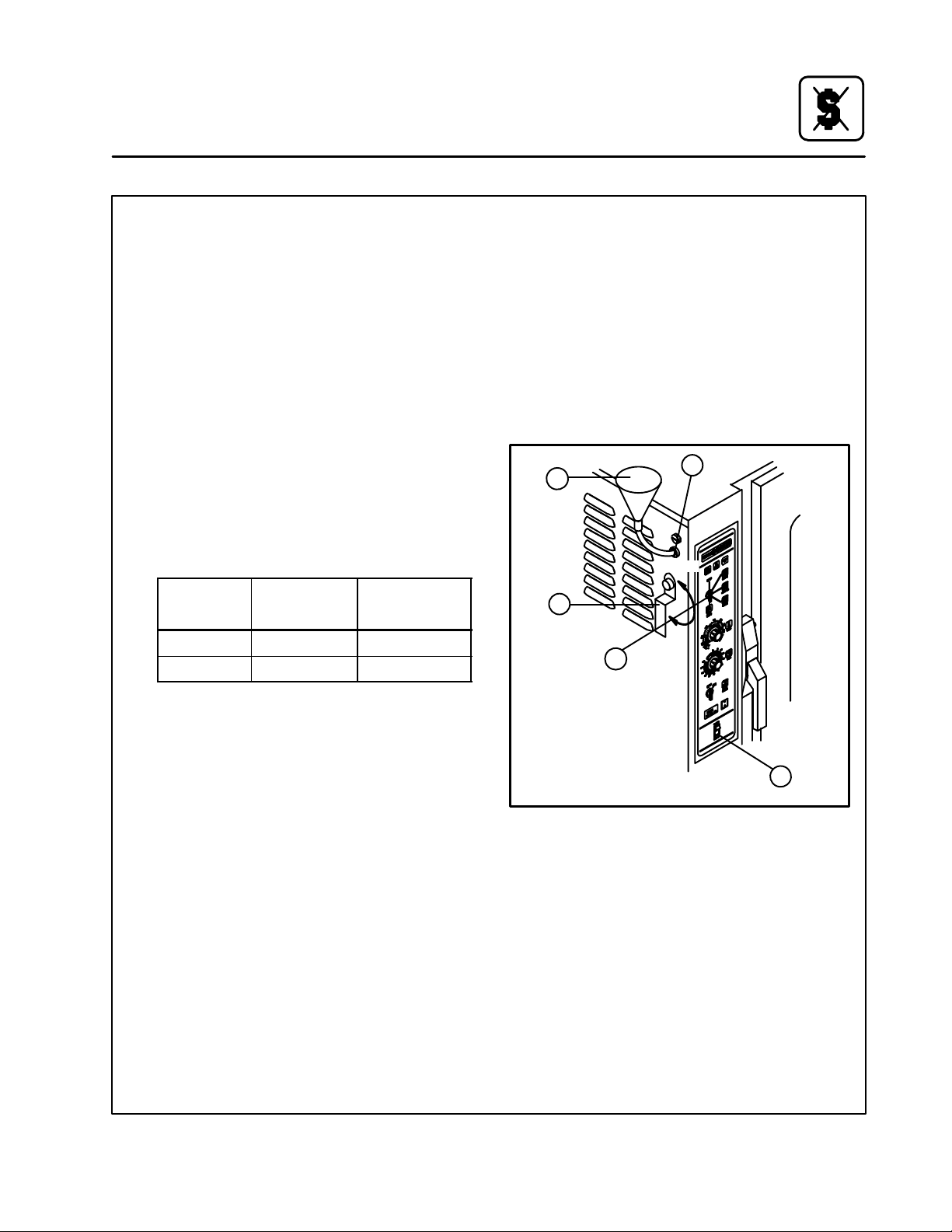
Entretien
Détartrage
REMARQUE:Cette procédure doit être utilisée
seulement avec les modèles COSĆ8E
et BCSĆ8E only.
1. Tourner le Commutateur de sélection de
mode (1) sur le mode VAPEUR. Attendre qu'il
y ait production de vapeur, ce qui assure que
l'eau dans le générateur de vapeur est
chaude.
2. Tourner le Commutateur de sélection de
mode (1) sur le mode REFROIDISSEMENT et
laisser la porte ouverte. Laisser le four se reĆ
froidir à 66_C, ce qui assure que l'interrupteur
Vidange/Chasse fonctionnera à l'ÉTAPE 8.
3. Tourner le Commutateur de sélection de
mode (1) sur ARRÊT.
4. Dans un récipient de bonne dimension, méĆ
langer la solution de détartrage et l'eau
chaude du robinet. Se reporter au tableau ciĆ
dessous pour connaître le bon dosage:
Solution
Modèle
COSĆ8E 888 ml 9.46 litres
BCSĆ8E 888 ml 9.46 litres
Détartrante
Eau chaude
du robinet
6. Ouvrir la vanne de l'orifice de détartrage (2) et
verser le mélange de détartrage. Arrêter de
verser quand l'entonnoir arrête d'absorber le
liquide. C'est la quantité correcte pour le site.
7. Fermer la vanne de l'orifice de détartrage (2).
Visser le bouchon de l'orifice de détartrage.
Laisser le mélange agir pendant 20 minutes.
Dans les zones d'eau dure, attendre 1 heure.
8. Enfoncer et tenir enfoncé l'interrupteur viĆ
dange/chasse (4) en position de CHASSE
pendant 90 secondes. Ceci complète le proĆ
cédé de détartrage.
3
2
1
5
ouvert
fermé
REMARQUE:Ces volumes sont approximatifs.
Vous pouvez avoir besoin de plus
ou moins d'eau chaude suivant le
site.
5. Retirer le bouchon de l'orifice de détartrage
(5). Attacher l'ensemble de l'entonnoir et du
tuyau (3) fournit, sur l'entrée de détartrage.
4
Figure 19
59
Page 64

INSERT
WIRING DIAGRAM
HERE
PLACEZ VOS
SCHÉMAS ÉLECTRIQUES
ICI
 Loading...