

Page 1

BCSĆ6
ELECTRIC COOKING APPLIANCES
INSTALLATION - OPERATION - MAINTENANCE
BLODGETT COMBI
www.blodgett.com
44 Lakeside Avenue, Burlington, Vermont 05401 USA Telephone (800) 331Ć5842, (802) 860Ć3700 Fax: (802)864Ć0183
PN R7701 Rev F (4/09)
E 2009 - Blodgett Combi
Page 2

A PERSONAL WORD
FROM BLODGETT COMBI
Congratulations on your purchase of a BLODGETT Combi appliance. We
firmly believe that your choice has been a wise one, and trust you will reĆ
ceive many years of excellent service from your new Combi.
You will find that cooking with Combi appliances saves time, labor and
extensive cleaning of both the kitchen and the unit.
With Combi appliances the quality, taste, consistency, and look of your
food are improved, thus endorsing the policy to which we've always adĆ
hered: For Better Cooking!"
Once you've had a chance to use your Combi, please tell us, your dealer
and colleagues about any creative and interesting applications you have
discovered; exchange ideas with other users. Be sure to advise us or
your dealer immediately should any mechanical or technical problems
be encountered (...we're here to help!) and above all Enjoy Cooking the
BLODGETT Combi Way!
For information on cooking, please refer to our separate cooking guide.
Page 3

IMPORTANT
WARNING: IMPROPER INSTALLATION, ADJUSTMENT,
ALTERATION, SERVICE OR MAINTENANCE CAN CAUSE
PROPERTY DAMAGE, INJURY OR DEATH. READ THE INĆ
STALLATION, OPERATING AND MAINTENANCE INĆ
STRUCTIONS THOROUGHLY BEFORE INSTALLING OR
SERVICING THIS EQUIPMENT
FOR YOUR SAFETY
Do not store or use gasoline or other flammable vapors or
liquids in the vicinity of this or any other appliance.
The information contained in this manual is important for the proper
installation, use, and maintenance of this oven. Adherence to these
procedures and instructions will result in satisfactory baking results
and long, trouble free service. Please read this manual carefully and
retain it for future reference.
Errors: Descriptive, typographic or pictorial errors are subject to correcĆ
tion. Specifications are subject to change without notice.
Page 4

Your Service Agency's Address:
Model:
Serial Number:
Your oven was installed by:
Your startĆup inspection service was
performed:
Date:
ASAP:
Page 5

Table of Contents
Introduction
The Convection Steamer 2. . . . . . . . . . . . . . . . . . . . . . . . . . . . . . . . . . . . . . . . . .
Description of the Convection Steamer 3. . . . . . . . . . . . . . . . . . . . . . . . . . . . . .
Steamer Features 4. . . . . . . . . . . . . . . . . . . . . . . . . . . . . . . . . . . . . . . . . . . . . . . .
Installation
Owner's Responsibilities 5. . . . . . . . . . . . . . . . . . . . . . . . . . . . . . . . . . . . . . . . . .
Location 6. . . . . . . . . . . . . . . . . . . . . . . . . . . . . . . . . . . . . . . . . . . . . . . . . . . . . . . .
Agency Approvals 7. . . . . . . . . . . . . . . . . . . . . . . . . . . . . . . . . . . . . . . . . . . . . . . .
Utility Connections 8. . . . . . . . . . . . . . . . . . . . . . . . . . . . . . . . . . . . . . . . . . . . . . .
Utility Connections 9. . . . . . . . . . . . . . . . . . . . . . . . . . . . . . . . . . . . . . . . . . . . . . .
Leg Attachment 10. . . . . . . . . . . . . . . . . . . . . . . . . . . . . . . . . . . . . . . . . . . . . . . . . .
Stacking 11. . . . . . . . . . . . . . . . . . . . . . . . . . . . . . . . . . . . . . . . . . . . . . . . . . . . . . . .
Adjustments 12. . . . . . . . . . . . . . . . . . . . . . . . . . . . . . . . . . . . . . . . . . . . . . . . . . . . .
Final Check Lists 13. . . . . . . . . . . . . . . . . . . . . . . . . . . . . . . . . . . . . . . . . . . . . . . . .
Operation
Standard Controls 14. . . . . . . . . . . . . . . . . . . . . . . . . . . . . . . . . . . . . . . . . . . . . . . .
Push Button Power Saver" Control 15. . . . . . . . . . . . . . . . . . . . . . . . . . . . . . . .
Maintenance
Spray Bottle Operating Procedure 16. . . . . . . . . . . . . . . . . . . . . . . . . . . . . . . . . .
Cleaning and Preventive Maintenance 17. . . . . . . . . . . . . . . . . . . . . . . . . . . . . .
Decalcification 18. . . . . . . . . . . . . . . . . . . . . . . . . . . . . . . . . . . . . . . . . . . . . . . . . . .
Page 6

Introduction
The Convection Steamer
Steaming āis āa wellĆknown cooking process freĆ
quently used in restaurant and institutional kitchĆ
ens. With the Blodgett Convection Steamer, it is
now possible to enjoy the many advantages of
steaming, some of which are:
Simplified Work Process
The work process is simplified since products are
prepared on or in steam table āpans āand trays.
Food can be cooked, stored, and transported with
āthe āsame āāpans. āSmall āamounts of product can be
processed efficiently; preĆcooked and conveĆ
nience foods can be rethermalized within minutes.
āMany frozen foods can be processed without preĆ
thawing. This flexibility in preparation reduces the
need for kettles and steam tables since there is no
need for large amounts of food to be kept warm for
long periods of time.
High Quality Foods
Today the improvement of food quality is more imĆ
portant than ever. With ātheā useāāā ofā steam,ā valuable
taste and aroma are preserved since steamed
foods retain their own natural taste. During the
steaming process foods retain the nutrients and
vitamins which are lost in water during boiling.
Therefore when compared, steamed foods have
much better color than foods that have been
boiled. āAlso,ā by using shallow containers the prodĆ
uct is not layered as deeply and mushing is
avoided.
Vitamin Retention
HOW STEAMING WORKS
The Blodgett Convection Steamer gently cooks
food using nonĆpressurized steam. Fresh steam is
directed into the unit from the generator. It is not
necessary to add water to foods during the steamĆ
ing process.
WHAT CAN BE STEAMED
Vegetables, side dishes, fish, meat, poultry, diet
foods, garnishes, dumplings, casseroles, meat
loaf, fruits, desserts and eggs.
In the Steam mode you can:
D steam
D defrost
D blanch
D poach
D rethermalize
In āthe āBlodgettā Convection Steamerā vitamins are not
destroyed. This is due to the shorter cooking times,
the use of less or little water and the use of a low temĆ
perature; slightly less than 212_F (100_C).
Firmness
With the use of steam, overcooking āisā notā a probĆ
lem and firmness can be individually controlled.
Simultaneously Steaming Different Foods
There is no flavor transfer when cookingā āwithā ātheā
āConvection Steamer. For this reason, various
types of food with different cooking times can be
loaded or removed at any point during the steamĆ
ing process.
2
Page 7

Introduction
Description of the Convection Steamer
ABOUT THE CONVECTION STEAMER
Blodgett Convection Steamers are quality proĆ
duced using highĆgrade stainless steel with first
class workmanship.
The high performance fresh steam generator with
its control system makes it possible to enjoy all of
the advantages of a high quality steamer at the
flick of a switch. Fresh steam enters the steamer
cavity without pressure and is circulated at high
speed. This process enables quick and gentle
cooking and ensures high quality food while proĆ
viding convenient working methods. The steam
generator is completely automatic and protected
from running dry.
A patented quench system keeps the air in the
steamer clean. Fumes are extracted from the
appliance, quenched, and directed out through
the condenser drain. This exhaust system results
in better quality foods and no flavor transfer. The
fan, which is guarded against accidental finger
contact, is driven by a quiet and powerful motor.
The condenser draws out excess steam from the
appliance. Condensation and waste water, which
result during steaming and cleaning, are continuĆ
ously drained.
The use of high quality insulation impedes excesĆ
sive heat radiation and saves energy.
The Convection Steamer has optional adjustable
legs which adapt easily to slightly uneven surfaces
and optional floor stands which are designed for
use with all of the tabletop models.
STEAMER OPERATION
The practical door, with a viewing window, has a
wide swing radius and handle which can be operĆ
ated easily, even with wet or greasy hands.
NOTE: Some models may be supplied with a solĆ
id door.
Ease of operation is guaranteed through the simĆ
ple arrangement of the controls. Graphic symbols
make the appliance easy for even inexperienced
kitchen staff to operate. Steam can be selected
with one switch.
The steamer is designed for easy care and is
welded water tight so that the internal cooking
cavity may be rinsed with a hose after the steam
cleaning process. For more detailed instructions
refer to the Maintenance section of this manual.
3
Page 8

Introduction
Steamer Features
7
Standard Features
8
10
3
9
2
1 Control Panel (standard control shown)
2 Power Connection
3 Steamer Door (glass door shown)
4 DripĂCollectorĂ(removableĂforĂcleaning)
5 Door Handle
4
5
6
1
Figure 1
6 Door Contact Switch
7 VentĂ(not shown)
8 Decalcifying Inlet & Funnel Assembly
9 Decalcifying Valve Lever
10 Tilt Down Panel Release Screw
4
Page 9

Installation
y
Owner's Responsibilities
1. Steamer(s) are uncrated, stacked (if applies)
and put in place.
NOTE: Please refer to Leg Attachment and
Stacking Addendum.
2. The owner/operator must have the following
plumbing and electrical requirements met and
installed.
NOTE: Refer to the Utility Connection inforĆ
mation provided.
PLUMBING
Water
Building Water Pressure (min/max) 40 PSI min / 50 PSI max
Cold Water Connection 3/4" Hose Fitting, 3/8" ID hose minimum
Water Regulator Setting 35 PSI static - preset
Drainage Atmospheric Vented Drain
WARNING!!
Improper installation, adjustment, alterĆ
ation service or maintenance can cause
property damage, injury or death. Read
the installation, operation and mainteĆ
nance instructions thoroughly before
installing or servicing this equipment.
Drain Connection 2" Copper
Avg Water Drain Temp. Approximately 122_F (50_C)
ELECTRICAL
Electrical 9.4 kw
Amp/line (max)
3
Volt
208 26 45
240 23 40
By
Mode
Blower Motor .33 HP / .4 kW
Steam 9kw
Hot Air 9kw
Combi 9kw
Phase
1
Phase
5
Page 10

Location
Installation
The well planned and proper placement of your
appliance will result in long term operator conveĆ
nience and satisfactory performance.
The following clearances must be maintained beĆ
tween the unit and any combustible or nonĆcomĆ
bustible construction.
D Steamer right side - 1" (2.54 cm)
D Steamer left side - 4" (10 cm) with casters
12" (30 cm) without casters
D Steamer back - 4" (10 cm)
NOTE: For models with hose assemblies on the
back of the unit, the hose must be 1" (2.54
cm) from the wall.
If optional casters are not used, the following
clearances are recommended for service.
D Steamer sides - 12" (30 cm)
D Steamer back - 12" (30 cm)
Place the unit in an area which is free of drafts and
accessible for proper operation and servicing.
Keep the oven area free and clear of all combusĆ
tibles such as paper, cardboard, and flammable
liquids and solvents.
DO NOT place the oven on a curb base or seal to
the wall; either condition will prevent proper ventiĆ
lation to the blower motors. Slight unevenness can
be corrected with the adjustable legs.
Heat sources must not be located near the air
vents on the left hand side of the unit. Consult the
factory for an optional protective side heat shield
kit if a warm surface or water source is to the left
of the unit. If excessive ambient temperature or a
water source is present a heat shield must be addĆ
ed to the left hand side of the oven to protect the
unit from excessive heat or water
D BCSĆ6 heat shield P/N R9047
On all models, tripping the blower motor's thermal
overload device indicates an excessive ambient
temperature at the side of the oven. This must be
corrected to prevent permanent damage to the
oven. All motor bearings are permanently lubriĆ
cated by the manufacturer; there is no need for
additional lubrication during the operational lifeĆ
time of the motors.
6
Page 11
Installation
Agency Approvals
THE INSTALLATION INSTRUCTIONS CONĆ
TAINED HEREIN ARE FOR THE USE OF QUALIĆ
FIED INSTALLATION AND SERVICE PERSONNEL
ONLY. INSTALLATION OR SERVICE BY OTHER
THAN QUALIFIED PERSONNEL MAY RESULT IN
DAMAGE TO THE STEAMER AND/OR INJURY TO
THE OPERATOR.
Qualified installation personnel are individuals, a
firm, a corporation, or a company which either in
person or through a representative are engaged
in, and responsible for:
D the installation of electrical wiring from the elecĆ
tric meter, main control box or service outlet to
the electric appliance.
Qualified installation personnel must be experiĆ
enced in such work, familiar with all precautions
required, and have complied with all requirements
of state or local authorities having jurisdiction.
U.S. and Canadian installations
All steamers, when installed, must be electrically
grounded in accordance with local codes, or in the
absence of local codes, with the National Electrical
Code, ANSI/NFPA 70-Latest Edition and/or CanaĆ
dian National Electric Code C22.2 as applicable.
Appliance is to be installed with backflow prevenĆ
tion in accordance with applicable federal, provĆ
ince and local codes.
General export installations
Installation must conform with Local and National
installation standards. Local installation codes
and/or requirements may vary. If you have any
questions regarding the proper installation and/or
operation of your Blodgett Convection Steamer,
please contact your local distributor. If you do not
have a local distributor, please call Blodgett Combi
at 0011Ć802Ć860Ć3700.
7
Page 12
Installation
Utility Connections
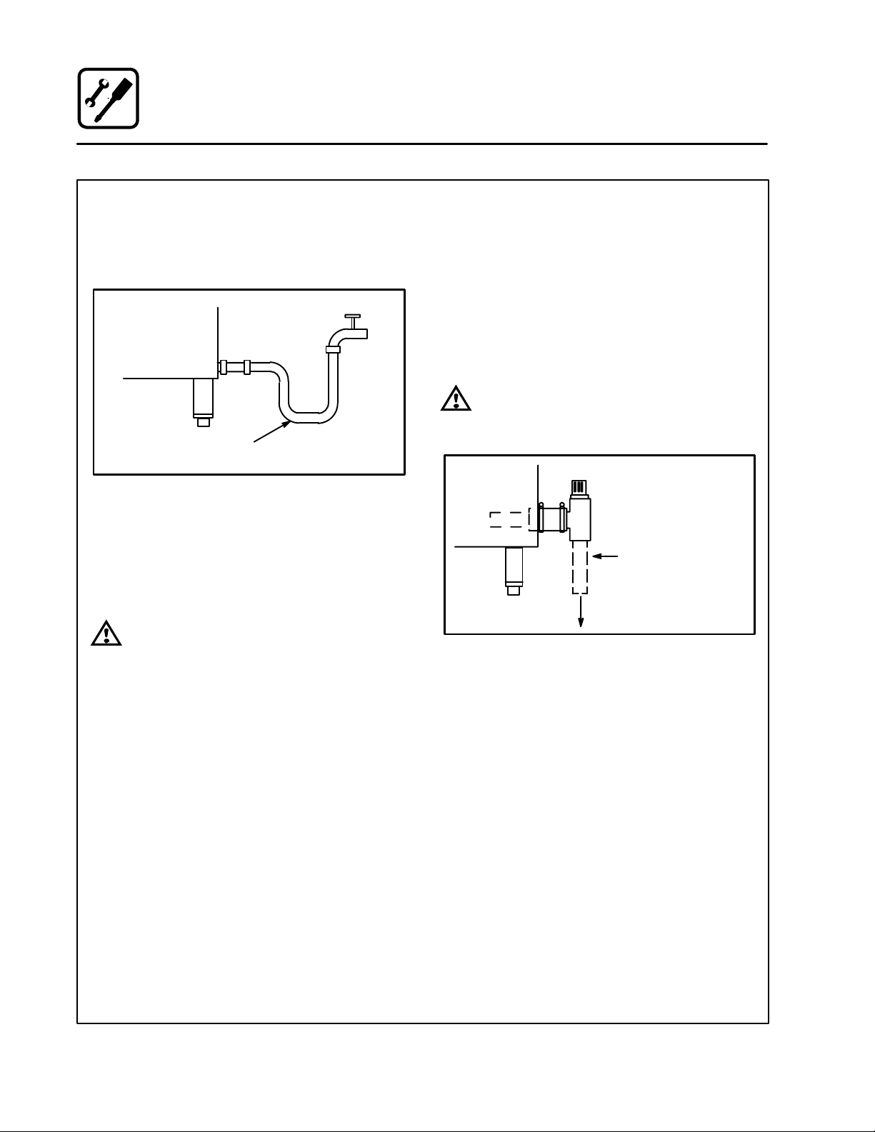
COLD WATER CONNECTION
Connect the appliance to quality water via a presĆ
sure hose with 3/4" couplings. A shut off valve is
to be provided adjacent to the steamer.
1/2" appliance hose
With 3/4" hose fittings
Figure 2
Water must meet the following minimum requireĆ
ments:
D Total Dissolved Solids (TDS) content will not exĆ
ceed 30 parts per million.
D Water PH must be 7.0 or higher
WARNING!!
The use of poor quality water will invaliĆ
date your warranty.
DRAIN CONNECTION
The Drain Vent assembly, included with the unit,
and a 2" (5 cm) copper pipe with standard drain
pitch, must be run to an open drain or connected
to a standpipe equipped with a vent.
NOTE: The waste water can also be directed to a
nearby floor drain. Flexible hose which alĆ
lows trapped water to accumulate in
sagged runs must be avoided.
WARNING!!
Failure to install the drain kit provided will
invalidate your warranty.
2" (5 cm) Drain
(Customer Supplied)
To Drain
Figure 3
8
Page 13
Installation
Utility Connections
ELECTRICAL CONNECTION
Before making any electrical connections to these
units, check that the power supply is adequate for
the voltage, amperage, and phase requirements
stated on the rating name plate mounted on the
right side of the unit.
Wiring diagrams are located on the inside of the
louvered side panel.
WARNING!!
Disconnect the power supply to the unit
before servicing.
U.S. and Canadian installations
All steamers, when installed, must be electrically
grounded in accordance with local codes, or in the
absence of local codes, with the National Electrical
Code, ANSI/NFPA 70-Latest Edition and/or CanaĆ
dian National Electric Code C22.2 as applicable.
General export installations
Installation must conform with Local and National
installation standards. Local installation codes
and/or requirements may vary. If you have any
questions regarding the proper installation and/or
operation of your unit, please contact your local
distributor. If you do not have a local distributor,
please call Blodgett Combi at 0011Ć802Ć860Ć3700.
NOTE: ALL MANUAL RESETS SHOULD BE REĆ
STORED BEFORE CONNECTING POWER
TO THE APPLIANCE.
WARNING!!
Improper installation will invalidate your
warranty.
9
Page 14

Installation
Leg Attachment
LEG VARIATIONS
Legs are available in 4" (101mm), 6" (152mm) āor
25" ā(635mm) ālengths āāor āālow profile casters. The 6"
legs are used on the lower section of a double
stacked unit. The 4" legs may be used with the opĆ
tional stands if additional height is required or
when mounting on a counter. The 25" legs are
used for a single unit located on the floor.
NOTE: For safety reasons, casters must not be
used with the 25" legs.
25" Adjustable Leg
LEG ATTACHMENT
NOTE: If low profile casters are used, install the
locking casters on the front of the oven.
The rear casters do not lock. Be sure the
locks are set on the front casters.
1. Align the threaded stud the each leg to the bolt
āholesā locatedāāā ināā ātheā āāunit'sā bottom ācorners.
Turn the legs clockwise and tighten to the
nearest full turn.
2. Align the leg plate holes with the bolt holes.
Secure with the two 1/2" bolts provided.
3. Tip the oven up on the legs. If ācastersā are
āused, checkā thatā the locksā areā setā on ātheā front
casters.
4. Except for units with casters, level the oven by
screwing the adjustable feet in or out as necĆ
essary.
6" Adjustable Leg
4" Leg
Low Profile Casters
Figure 4
6" (15 cm) Legs Shown
Figure 5
10
Page 15

1. Install the casters as directed.
2. Center āthe upper āunit on top of the lower secĆ
tion.
3. Remove āthe āscrews from the rear āaccess āpanĆ
el āand remove the access panel from the botĆ
tom unit.
4. Carefully āremove āthe āfan āāplug āand disasĆ
semble the steam vent.
NOTE: The fan plug connector can be easily
damaged
5. Alignā theā two rear bolt holes in the lower secĆ
tion with the two threaded holes in the upper
section.
6. Insertā a ābolt from the bottom up through each
of the two holes and tighten securely.
7. Reassemble the steam vent and reconnect
the fan plug. Reinstall the rear access panel
on the lower unit.
Installation
Stacking
Figure 6
11
Page 16
Installation
Adjustments
BEFORE SWITCHING THE APPLIANCE ON
Before applying power to the unit for the first time,
check for the following conditions:
j All āelectricalā safety provisions have been adĆ
hered to and the electrical connections are
correct.
j Water is connected, turned on and all of the
connections are water tight.
j The āāgrease āfilter āand āholder āare āin ātheir proper
positions.
j The āpanā holders are āinserted āinto the steamer
cavity.
WARNING!!
If the fan turns in the wrong direction, the
appliance will not function properly and
can be damaged.
NOTE: When the unit is turned on, or after it has
been OFF for 5 hours and then turned on,
āthe steam generator āautomatically flushes
for 75 seconds. The steam generator then
fills to the proper water level. The unit is
now ready for operation.
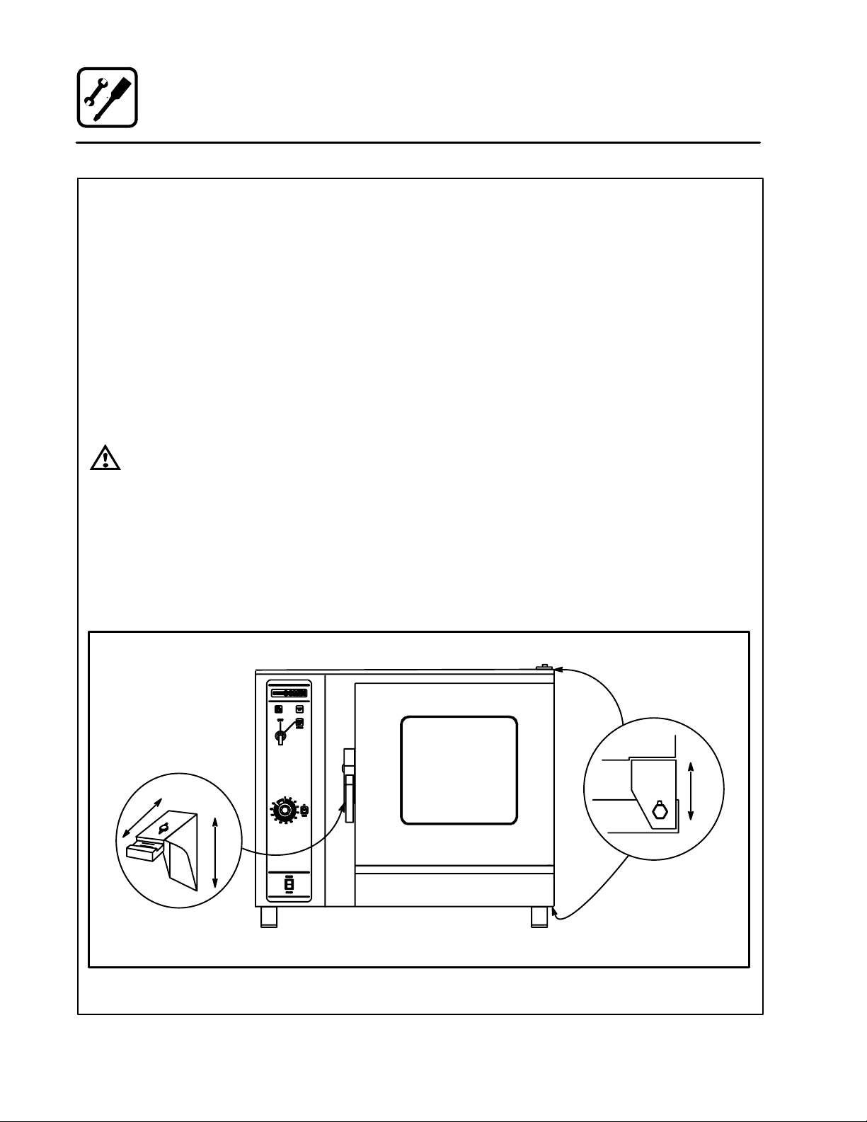
DOOR ADJUSTMENT
The door latch may be adjusted in two directions,
in and out, and up and down, using the following
procedure:
1. Adjust up and down by loosening the two boltsā
holdingā theā latch to the face of the unit (A).
2. Make āadjustmentsā soā thatā theā leadingā face of
the latch is centered in the opening of the hanĆ
dle assembly.
3. Tighten the bolts so that there is no further
movement.
4. Adjust in and out by loosening the bolt on top
of the latch (B).
5. The āāadjustment āāface āāis āstepped āso āthat moveĆ
ment is limited with the bolt tightened properly.
6. The āadjustment āis ācorrect āwhen āthe ādoor closes
firmly and no steam leaks from the gasket.
The hinges can also be adjusted as follows:
1. Be certain the latch is adjusted properly.
2. Adjustā hinges āso āthatā the door back and the
unit face are parallel (C).
3. The adjustment is correct when no steam
leaks through the gasket.
Steamer
C
B
A
Figure 7
12
Door
Page 17

Installation
Final Check Lists
ELECTRICAL CONTROL COMPARTMENT
Applied voltage to unit voltage/phase suitable for
appliance specified.
j Remove side panel
j Set motor protector (F2) to on position (480V
only)
j Adjust motor protector to maximum
j Reset high limit thermostat F6
j Check fuses
j Reinstall side panel
PLUMBING FINAL CHECK
j Incoming water pressure within 40 PSI (miniĆ
mum) - 50 PSI (maximum)
j Atmospheric vented drain in place
j Water solenoid properly bracketed and not
leaking
j Water feed lines intact without leaks
j Water pressure regulator is set to 35 psi
j Spray hose connected properly
STEAMER OPERATIONAL TESTS
NOTE: Checks to be made by customer or authoĆ
rized service agent.
Turn on STEAM mode and verify (control panel reĆ
moved):
j Check timer operation in all three positions
1. Set timer to OFF position, buzzer should
sound
2. Set timer in position other than OFF or
STAY ON, timer should count down
3. Set timer in STAY ON position, steamer
should operate continuously without timer
j Run light (power light) turns on
j Unit produces steam, window fogs, door seal
does not leak
j Quenching system working
Fill
Solenoid
Washer
Washer
Regulator Assembly
Y" Fitting
Cold water supply
Hose and Spray
Spray Hose Connection
Figure 8
13
Page 18

Operation
Standard Controls
1
3
CONTROLS IDENTIFICATION
1. LOW WATER FILL LIGHT - during the fill
cycle, this light remains on until the water in
the steam generator is at the proper level and
up to temperature. During normal operation the
light should not be on. If the light comes on,
2
check the water level in the steam generator.
2. POWER ON LIGHT - Indicates the unit is in
Steam mode.
3. MODE SELECTOR SWITCH - Turns power
to the steamer on or off. Allows selection of
steam mode.
4. TIMER DIAL - Used to set desired steam
time. Some models may be supplied with a
push button reset switch.
5. FLUSH/DRAIN SWITCH - Used to flush/
drain the steam generator during decalcificaĆ
tion.
OPERATION
1. Turn the mode selector switch to STEAM.
2. The green POWER Indicator lamp on the front
control panel lights.
3. The steam generator flushes and drain autoĆ
matically for 75 seconds if the unit has been off
4
5
for at least 5 hours.
4. The steam generator begins to fill. After two
minutes, the FILL indicator lamp on the front
control panel blinks. The convection blower
and POWER lamp turn off.
5. When the steam generator is filled to the propĆ
er level, the convection blower, interior lights
and POWER indicator lamp turn on.
6. Steam fills the cavity and is controlled by a
nonĆaccessible internal thermostat.
Figure 9
14
Page 19

Operation
Push Button Power Saver" Control
CONTROLS IDENTIFICATION
1. LOW WATER FILL LIGHT - during the fill
cycle, this light remains on until the water in
the steam generator is at the proper level and
up to temperature. During normal operation the
light should not be on. If the light comes on,
1
3
2
check the water level in the steam generator.
2. POWER ON LIGHT - Indicates the unit is in
Steam mode.
3. MODE SELECTOR SWITCH - Turns power
to the steamer on or off. Allows selection of
steam mode.
4. RESET PUSH BOTTON - Turns on steamer
when door is closed. Must be pushed to start
steamer every time the door is opened.
5. FLUSH/DRAIN SWITCH - Used to flush/
drain the steam generator during decalcificaĆ
tion.
4
5
OPERATION
1. Turn the mode selector switch to STEAM.
2. The green POWER Indicator lamp on the front
control panel lights.
3. With the door closed, push and release the
RESET button. The steamer comes one and
begins steaming.
4. Open the door to shut off the steamer.
Figure 10
15
Page 20

Maintenance
Spray Bottle Operating Procedure
1. Unscrewāā ātheā āāsprayerāāā āhead āāāāandāāā āfillā āāāthe containĆ
er to the MAX mark. Screw the head assembly
āon āfirmlyā toā āensureā āan āāairtight seal. The liquid
must be clean and free from foreign matter. Do
not overfill Ć space must be left for compressĆ
ing air.
2. To build up pressure, pump approximately 20
full strokes when the container is filled with liqĆ
uid. The higher the pressure, the finer the
spray. If the container is only partially filled,ā
then āmoreā pumping āāis āārequired āto compress
the additional air space.
3. To spray, depress the trigger with your thumb.
4. After a period of spraying, the pressure will
drop. Restore the pressure by operating the
air pump.
5. Release pressure after use by inverting the
spray head and depressing the trigger or byā
slowly āunscrewing ā theā spray āhead assembly
āwhichā willā allow āairā toā escape āfrom around āāāthe
filling aperture.
6. Afterā use,ā rinse āthe āsprayā bottleā withā clean waĆ
ter and check that the hole in the nozzle is āperĆ
fectly āclean āand clear. Warm water (notā hot)ā
usedā withā aā household ādetergent is a useful
cleaning agent for this purpose.
NOTE: Further information can be found in the inĆ
struction leaflet supplied with your spray
bottle.
Service Parts:
Complete spray bottle P/N R0006
Spray nozzle repair kit P/N R6332
WARNING!!
Protective clothing and eye wear should
be worn while using cleaning agents.
Pressure Pump
Spray Head
Pump
MAX
Pressure
Vessel
Clean the pump 2 or 3 times per week with warm water
Spray Trigger
Figure 11
16
Page 21

Maintenance
Cleaning and Preventive Maintenance
CLEANING THE INTERIOR
Daily cleaning of the appliance is essential for sanĆ
itation and to ensure against operational difficulĆ
ties. Use an oven cleaning detergent in conjuncĆ
tion with the supplied spray bottle.
On stainless interiors, deposits of baked on splatĆ
ter, oil, grease or light discoloration āmay ābe āreĆ
moved āwith āa good non toxic industrial stainless
steel cleaner. Apply cleaners when the unit is cold
and always rub with the grain of the metal. The
racks, rack supports and the blower wheel may be
cleaned either in the unit or removed āand āsoaked
in a solution of ammonia and water.
NOTE: DO NOT use corrosive cleaners!
1. Cool āāthe āappliance down to 140_F (60_C) or,
if the āunitāā has āābeenā āidle, āāturnā the steam modeā
onā foār 3 āto ā4ā minutesā inā order āāāto warm the interiĆ
or surfaces.
2. Fill āāāāātheāāā āsprayāāā ābottleā āāandāāā pump āāāairā āāintoāā āthe conĆ
tainer with the pressure pump.
3. Spray āāthe āinteriorā of āātheāā unitā with a cleaning soĆ
lution.
NOTE: Never spray water into the unit when
the temperature is above 212_F.
4. Let āthe ācleanerā āworkāā for āā10ā toā 20 minutes withāāāāā
the āāāāunitā āāāāoff.āāā āForā āādifficult cleaning allow to work
over night.
5. Set the timer for 15 to 20 minutes. Turn ātheā
āmodeā āāselector switch to Steam. This will softĆ
en all burned on residue.
6. Rinseāā āāthe interiorā āāāwithāāāāā the hose and spray asĆ
sembly.
7. Setā āāātheā āāāmode āāāselectorāāā toā āāsteam āāāforā anotherā five
minutes to flush out the interior and remove all
detergent residue.
NOTE: The āinterior ācavity ā should ā never ā be
scoured or scraped.
CLEANING THE EXTERIOR
Exteriors may be cleaned and kept in good condiĆ
tion with a stainless steel polish.
NOTE: DO NOT spray the outside of the appliance
with water.
PREVENTIVE MAINTENANCE
The best preventive maintenance measures are:
D the āāāproper āāinitial āāinstallation āāof āāthe equipment
D deliming the steam generator (if applicable)
D a program for routine cleaning.
These units requires no lubrication. Contact the
factory, a factory representative or a local Blodgett
Combi service company to perform maintenance
and repairs should they be required.
WARNING!!
Disconnect the appliance from the power
supply before servicing or cleaning.
17
Page 22

Maintenance
Decalcification
1. Turn the Mode Selection Switch (1) to the
STEAM mode. Wait until steam is produced.
This will ensure that the water in the steam
generator is hot.
2. Turn the Mode Selection Switch (1) to the
COOL DOWN mode and leave the door open.
Let the oven compartment cool to 150_F
(66_C). This ensures that the Drain/Flush
switch will function in STEP 8.
3. Turn the Mode Selection Switch (1) to OFF.
4. In a suitable size container, mix together the
deliming solution and tap water. Refer to the
following chart for the proper mixture:
Deliming
Model
BCSĆ6 12 oz. 3 quarts
NOTE: These volumes are approximate. You
may need slightly more or less water
depending on your site.
5. Remove the Deliming Port Cap from the DeĆ
liming Inlet (5). Attach the supplied Funnel
and Hose Assembly (3) to the deliming inlet.
6. Open the Deliming Port Valve (2) and pour in
the deliming mixture. Stop pouring when the
funnel stops draining. This is the correct
amount for your site.
Solution Tap Water
7. Shut the Deliming Port Valve (2). Screw on the
Deliming Port Cap. Let the mixture stand for 20
minutes. In areas of the country with hard waĆ
ter, allow the mixture to stand for 1 hour maxiĆ
mum.
8. Depress and hold the Drain/Flush Switch (4)
in the FLUSH position for 90 seconds. This
completes the deliming procedure.
3
open
2
close
1
4
Figure 12
18
Page 23

INSERT
WIRING DIAGRAM
HERE
 Loading...