

Blizzard Snowplow 760HD Installation And Owner's Manual

April 1, 2006
Lit. No. B64090, Rev. 00
Models 760LT, 760HD, 800HD & 860HD
Installation Instructions & Owner's Manual
Read this manual before operating or servicing
snowplow.
This document supersedes all editions with an earlier date.
CAUTION

PREFACE
Congratulations on purchasing the finest straight blade
snowplow available! BLIZZARD® straight blades are
clearing new trails for innovative design, rugged
durability, quality craftsmanship and superior
performance. Our exclusive products are
manufactured and tested in Michigan’s Upper
Peninsula, the snow capital of the Midwest. With an
annual snowfall averaging over 250" we couldn’t
imagine building snow removal products anywhere
else!
April 1, 2006 2 Lit. No. B64090, Rev. 00

TABLE OF CONTENTS
Preface ....................................................................... 2
Safety Information ...................................................... 4
Operation ................................................................... 7
Unpacking & Inspection.............................................. 8
Torque Specifications ................................................. 9
Moldboard & A-Frame Assembly .............................. 11
Electrical & Hydraulic Systems ................................. 16
General System Schematics.............................. 16
Hydraulic Guide ................................................. 17
Electrical Installation – Snowplow Side .............. 18
Electrical Schematics – Snowplow Side ............ 19
Electrical Installation – Vehicle Side .................. 22
Electrical Schematics – Vehicle Side ................. 25
POWER HITCH™ System Instructions .................... 29
Testing Your Snowplow ............................................ 30
Headlight Aiming ...................................................... 32
Maintenance ............................................................. 33
Technical Specifications ........................................... 34
Troubleshooting........................................................ 35
Notes ........................................................................ 37
Parts Lists................................................................. 38
Moldboard & Wing Parts – All Models................ 38
A-Frame & Pivot Beam Parts – All Models ......... 40
Power Unit Parts – All Models............................ 42
Lights, Draw Latch & Control Parts – All Models . 44
Harnesses, Accessories & Kits – All Models ...... 46
Notes ........................................................................ 51
Lit. No. B64090, Rev. 00 3 April 1, 2006
SAFETY
SAFETY DEFINITIONS
WARNING
Indicates a potentially hazardous situation,
that if not avoided, could result in death or
serious personal injury.
CAUTION
Indicates a potentially hazardous situation
that, if not avoided, may result in minor or
moderate injury. It may also be used to alert
against unsafe practices.
NOTE: Indicates a situation or action that can lead
to damage to your snowplow and vehicle or other
property. Other useful information can also be
described.
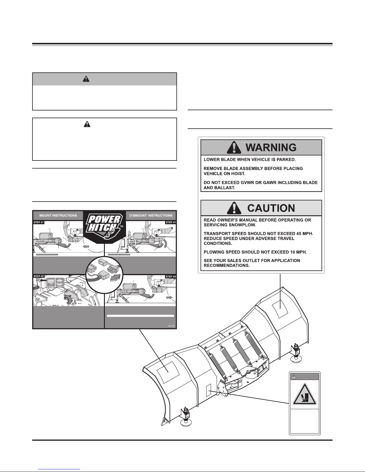
CONNECT/DISCONNECT
Power Hitch Switch
CAUTION: KEEP FINGERS AWAY!
• Kickstand should be in the lowered position.
• Slowly drive vehicle forward until the push beam receiver
mount points contact the A-frame mount bushings.
• Turn POWER HITCHOPERATION switch (on plow control)
to the "ON" position.
• Connect plow and vehicle electrical harnesses.
• Pull A-frame latch lock pin out and lower the latch over the draw pin.
• Push and hold the CONNECT/DISCONNECT switch upward. The Power Hitch
will engage the back of the push beam and pull the plow into the push beam
receiver mount points on the vehicle.
• Insert both hitch pins and secure each with a hair pin cotter.
• Lower Power Hitch to relieve tension on the A-frame latch. Raise the A-frame
latch into its locked position. Raise plow to the full up position.
• Raise kickstand until it locks into place. The plow is now properly mounted.
Push Beam
Receiver
Mount Points
Undercarriage
Adjustable
Kickstand
A-Frame Latch
Rotates Clockwise
And Hooks Onto
Draw Pin
Push Beam
Power
A-frame
Hitch
Mount Bushing
POWER HITCH RAISES BEHIND UNDERCARRIAGE PUSH BEAM.
A-Frame
Latch
Lock Pin
A-Frame
Latch
Slowly Move
Vehicle Forward
Draw
Pin
Connect electrical harness
plugs to mount plow and
disconnect plugs prior
CAUTION: KEEP FINGERS AWAY!
to dismounting plow
• Push and hold the CONNECT/DISCONNECT switch downward. The Power
Hitch will disengage from behind the undercarriage push beam and lower.
CAUTION:
• Disconnect plow and vehicle electrical harnesses. Install weather caps.
• Turn SYSTEM POWER (on plow control) to the "OFF" position.
• Slowly back vehicle away from plow.
CONNECT/DISCONNECT
Power Hitch Switch
Adjustable
Kickstand
Power
POWER HITCH LOWERS FROM UNDERCARRIAGE PUSH BEAM.
• With the plow fully raised, lower the kickstand.
• Lower plow on a flat, level surface. Turn vehicle ignition off.
• Remove hitch pins from the A-frame and undercarriage.
• Turn vehicle ignition on.
• Verify POWER HITCH OPERATION switch (on plow control)
is in the "ON" position.
CONNECT/DISCONNECT
Power Hitch Switch
Adjustable
Kickstand
KEEP FINGERS AWAY FROM PLOW & TRUCK MOUNTING POINTS!
Hitch
Slowly Back
Vehicle Away
Power
Hitch
WARNING/CAUTION & INSTRUCTION
LABELS
Become familiar with and inform users about the
warning and instruction labels on the back of the
blade.
NOTE: If labels are missing or cannot be read, see
your sales outlet.
April 1, 2006 4 Lit. No. B64090, Rev. 00
WARNING
Crush
hazard.
Keep feet
clear.
SAFETY
SAFETY PRECAUTIONS
Improper installation and operation could cause
personal injury, and/or equipment and property
damage. Read and understand labels and the Owner's
Manual before installing, operating or making
adjustments.
WARNING
Lower blade when vehicle is parked.
Temperature changes could change hydraulic
pressure, causing the blade to drop
unexpectedly or damaging hydraulic
components. Failure to do this could result in
serious personal injury.
WARNING
You can die or be seriously injured. Keep
hands and feet away from hitch mechanism
and snowplow blade when operating the
POWER HITCH™ arm. The action of the arm
moves the snowplow toward the vehicle and
into position for proper attachment.
CAUTION
Read Owner's Manual before operating or
servicing snowplow.
CAUTION
Transport speed should not exceed 45 mph.
Reduce speed under adverse travel conditions.
CAUTION
Plowing speed should not exceed 10 mph.
CAUTION
See your BLIZZARD® outlet for application
recommendations.
CAUTION
To prevent accidental movement of the blade,
always turn the ON/OFF switch to OFF whenever
the snowplow is not in use. The control indicator
light (touchpad only) will turn off.
WARNING
The driver shall keep bystanders clear of the
blade when it is being raised, lowered or
angled. Do not stand between the vehicle and
the blade or within 8 feet of a moving blade. A
moving or falling blade could cause personal
injury.
WARNING
Do not exceed GVWR or GAWR including the
blade and ballast. The rating label is found on
the driver-side vehicle door cornerpost.
WARNING
Remove blade assembly before placing vehicle
on hoist.
HYDRAULIC SAFETY
WARNING
Hydraulic fluid under pressure can cause skin
injection injury. If you are injured by hydraulic
fluid, get medical attention immediately.
• Always inspect hydraulic components and hoses
before using. Replace any damaged or worn parts
immediately.
• If you suspect a hose leak, DO NOT use your
hand to locate it. Use a piece of cardboard or
wood.
FUSES
The electrical and hydraulic systems contain several
automotive blade-style fuses. If a problem should occur
and fuse replacement is necessary, the replacement
fuse must be of the same type and amperage rating as
the original. Installing a fuse with a higher rating can
damage the system and could start a fire.
Lit. No. B64090, Rev. 00 5 April 1, 2006

SAFETY
PERSONAL SAFETY
• Remove ignition key and put the vehicle in park or
in gear to prevent others from starting the vehicle
during installation or service.
• Wear only snug-fitting clothing while working on
your vehicle or snowplow.
• Do not wear jewelry or a necktie, and secure long
hair.
• Wear safety goggles to protect your eyes from
battery acid, gasoline, dirt and dust.
• Avoid touching hot surfaces such as the engine,
radiator, hoses and exhaust pipes.
• Always have a fire extinguisher rated BC handy,
for flammable liquids and electrical fires.
FIRE AND EXPLOSION
WARNING
Gasoline is highly flammable and gasoline
vapor is explosive. Never smoke while working
on vehicle. Keep all open flames away from
gasoline tank and lines. Wipe up any spilled
gasoline immediately.
BATTERY SAFETY
CAUTION
Batteries normally produce explosive gases
which can cause personal injury. Therefore, do
not allow flames, sparks or lit tobacco to come
near the battery. When charging or working
near a battery, always cover your face and
protect your eyes, and also provide ventilation.
Batteries contain sulfuric acid which burns
skin, eyes and clothing.
Disconnect the battery before removing or
replacing any electrical components.
NOISE
Airborne noise emission during use is below 70 dB(A)
for the snowplow operator.
Be careful when using gasoline. Do not use gasoline
to clean parts. Store only in approved containers away
from sources of heat or flame.
VENTILATION
WARNING
Vehicle exhaust contains lethal fumes.
Breathing these fumes, even in low
concentrations, can cause death. Never
operate a vehicle in an enclosed area without
venting exhaust to the outside.
April 1, 2006 6 Lit. No. B64090, Rev. 00
OPERATION
Your snowplow is the most advanced and versatile
straight blade on the market. The easy-to-use controls
allow you to automatically adjust the plow blade into an
infinite number of plowing positions. Review the
illustrations below for instruction on maneuvering your
snowplow.
A.
B.
A. Lowered or Float Position
Pushing the joystick forward, toward the
"Lower/Float" designation on the label, or pushing
the "D" button on the touchpad will lower your
straight blade to the ground. Pushing and
momentarily holding the control in this position will
allow the snowplow to "float", or follow the contour
of the ground when moving forward or backward.
B. Raised Position
Pulling the joystick back, toward the "Raise"
designation on the label, or pushing the "U" button
on the touchpad will lift your straight blade off of
the ground. To stop raising the plow, simply return
the joystick to its "neutral", or center, position or
release the touchpad button. The snowplow has
reached its maximum raised position when the
blade stops lifting.
C. Angled Right Position
To angle your straight blade to the right, position
the joystick toward the "R" on the label or push the
"R" button on the touchpad. To stop angling the
plow, return the joystick to its "neutral" or center
position or release the touchpad button. The
snowplow has reached its maximum angled
position when the blade stops moving to the right
side.
C.
D.
D. Angled Left Position
To angle your straight blade to the left, position the
joystick toward the "L" on the label or push the "L"
button on the touchpad. To stop angling the plow,
return the joystick to its "neutral" or center position
or release the touchpad button. The snowplow has
reached its maximum angled position when the
blade stops moving to the left side.
NOTE: To prevent premature failure of the power
contactor (solenoid), return the joystick to its
neutral (center) position or release the touchpad
button immediately after the blade reaches the
limit of any position. Continuing to hold the control
after the blade has reached the limit of movement
in any position will reduce the life of the solenoid.
Lit. No. B64090, Rev. 00 7 April 1, 2006

UNPACKING & INSPECTION
Blizzard Model 800 HD
060216650000B0800
Serial
Number
Model
Your BLIZZARD® straight blade has been packaged to
withstand transit and weather related damage. Fully
inspect all components upon receipt of your plow. In
the event of shipping damage or missing parts,
immediately contact our Customer Service
Department at 1-888-680-8600.
Begin unpacking and inspection in the following order:
1. Remove the shipping document from the end
panel of the pallet wrap. Retain all documentation
for your records.
2. All wood framing and polyethylene material should
be removed from the pallet for easy access to the
snowplow.
3. Due to the odd shaped components and size of
several assembly parts, various cable ties and
corrugated material are used for scratch
resistance and package orientation. Please
remove these items prior to assembly.
4. Place the main blade assembly on a flat, level
surface.
Serial Number Labels
The serial number label on the back of the blade
(driver side) contains important information about the
snowplow. The serial number is displayed directly
above the bar code, and the model information is
above the serial number. The first six digits in the
serial number represent the manufacture date of the
snowplow. This date is formatted "yymmdd", in the
example below, the manufacture date would be
February 16, 2006. A similar label can also be found
on the hydraulic unit. The manufacture date is, again,
the first six digits of the serial number. Be sure to note
both serial numbers in the area at the bottom of the
preceding column.
Once you have inspected all parts and removed all
packaging materials, your snowplow is ready to be
fully assembled.
Retain this information for your records.
Date of Purchase: ___________________________
Dealer/Distributor: __________________________
Dealer Phone Number: _______________________
Snowplow Serial Number: ____________________
Hydraulic Pump Serial Number: _______________
April 1, 2006 8 Lit. No. B64090, Rev. 00

TORQUE SPECIFICATIONS
TORQUE CHART
CAUTION
Read instructions before assembling.
Fasteners should be finger tight until
instructed to tighten according to the torque
chart. Use standard methods and practices
when attaching snowplow including proper
personal protective safety equipment.
Grade Identification for J429–Grade 5 Bolt Grade Identification for J429–Grade 8 Bolt
SAE J429 Grade 5 Torque Values SAE J429 Grade 8 Torque Values
Nominal
Thread Size
1/4-20 2,000 6 ft-lbs 8 ft-lbs 1/4-20 2,850 9 ft-lbs 12 ft-lbs
5/16-18 3,350 13 ft-lbs 18 ft-lbs 5/16-18 4,700 18 ft-lbs 25 ft-lbs
3/8-16 4,950 23 ft-lbs 31 ft-lbs 3/8-16 6,950 32 ft-lbs 44 ft-lbs
7/16-14 6,800 37 ft-lbs 50 ft-lbs 7/16-14 9,600 53 ft-lbs 70 ft-lbs
1/2-13 9,050 57 ft-lbs 75 ft-lbs 1/2-13 12,800 80 ft-lbs 107 ft-lbs
9/16-12 11,600 82 ft-lbs 109 ft-lbs 9/16-12 16,400 115 ft-lbs 154 ft-lbs
5/8-11 14,500 113 ft-lbs 151 ft-lbs 5/8-11 20,300 159 ft-lbs 211 ft-lbs
3/4-10 21,300 200 ft-lbs 266 ft-lbs 3/4-10 30,100 282 ft-lbs 376 ft-lbs
7/8-9 29,435 321 ft-lbs 430 ft-lbs 7/8-9 41,550 454 ft-lbs 606 ft-lbs
1-8 38,600 482 ft-lbs 640 ft-lbs 1-8 54,540 680 ft-lbs 900 ft-lbs
Clamp Loads
(lbs)
Tightening Torque Tightening Torque
"Lubricated" "Dry"
Nominal
Thread Size
Clamp Loads
(lbs)
"Lubricated" "Dry"
Grade Identification for Metric–Grade 8.8 Bolt Grade Identification for Metric–Grade 10.9 Bolt
Metric Class 8.8 Torque Values Metric Class 10.9 Torque Values
Diameter
(mm)
5 1,389 3 ft-lbs 5 ft-lbs 5 1,987 5 ft-lbs 7 ft-lbs
6 1,965 6 ft-lbs 8 ft-lbs 6 2,812 8 ft-lbs 11 ft-lbs
7 2,826 10 ft-lbs 13 ft-lbs 7 4,044 14 ft-lbs 19 ft-lbs
8 3,579 14 ft-lbs 19 ft-lbs 8 5,121 20 ft-lbs 27 ft-lbs
10 5,672 28 ft-lbs 37 ft-lbs 10 8,116 40 ft-lbs 53 ft-lbs
12 8,243 49 ft-lbs 65 ft-lbs 12 11,796 70 ft-lbs 92 ft-lbs
14 11,246 77 ft-lbs 103 ft-lbs 14 16,092 111 ft-lbs 148 ft-lbs
16 15,882 125 ft-lbs 167 ft-lbs 16 21,970 173 ft-lbs 231 ft-lbs
18 19,423 172 ft-lbs 229 ft-lbs 18 26,868 238 ft-lbs 317 ft-lbs
20 24,784 244 ft-lbs 325 ft-lbs 20 34,284 338 ft-lbs 450 ft-lbs
Clamp Loads
(lbs)
Tightening Torque Tightening Torque
"Lubricated" "Dry"
Diameter
(mm)
Clamp Loads
(lbs)
"Lubricated" "Dry"
Lit. No. B64090, Rev. 00 9 April 1, 2006

Turns Size
N/A -02 6-7
N/A -03 8-9
2 -04 11-12
2 -05 14-15
1-1/2 -06 18-20
1-1/2 -08 36-39
1-1/2 -10 57-63
1-1/4 -12 79-88
1 -14 94-103
1 -16 108-113
1 -20 127-133
1 -24 158-167
1 -32 245-258
Size
-02 6-7
-03 8-10
-04 13-15
-05 17-21
-06 22-25
-08 40-43
-10 43-57
-12 68-75
-14 90-99
-16 112-123
-20 146-200
-24 154-215
-32 218-290
Ft-lbs
min.max
Ft-lbs
min.max
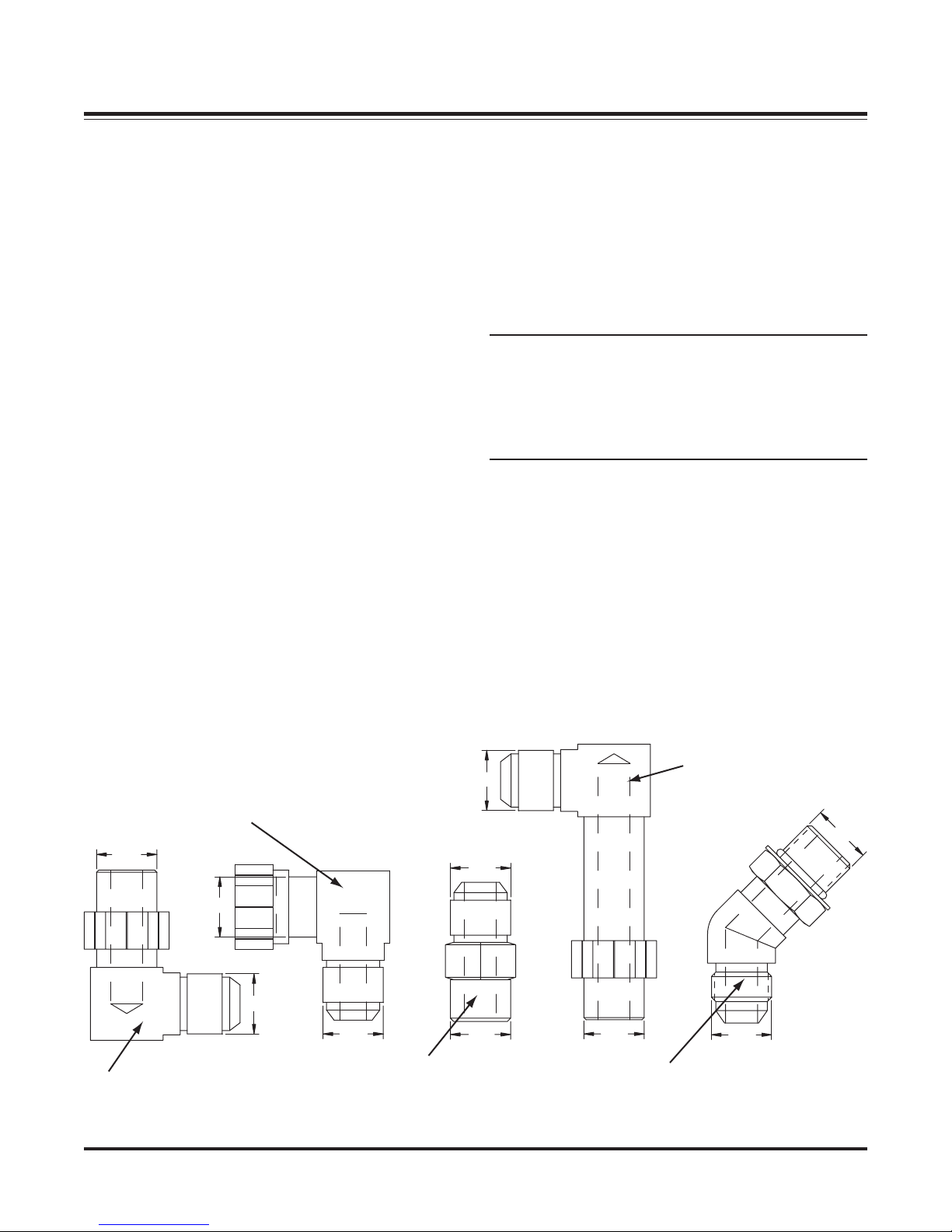
Assembly Steps
1. Verify the port, o-ring, sealing surfaces and threads are clean and free of damage.
2. Lubricate the threads and the o-ring with 10W hydraulic oil.
3. For an adjustable O.R.B., completely back off the lock nut and washer.
4. Hand tighten the fitting until it contacts the port spotface. Point the elbow or tee in the desired direction
and hold.
5. Torque to specification.
NOTE: Torque values specified are for threads lubricated with 10W hydraulic oil.
TORQUE SPECIFICATIONS
37° JIC Flare Torque Values
Assembly Steps
1. Make sure the tubing and threads are clean.
2. Lubricate the threads with 10W hydraulic oil.
3. Hand tighten the nut/sleeve to approx. 30 in-lbs.
4. Make alignment marks on the nut and fitting.
5. Tighten to turn or torque specification.
6. When fully tightened, make a 2
NOTE: Torque values specified are for threads lubricated with 10W hydraulic oil.
Over tightening will reduce the clamping force resulting in loss of seal and reduction of flow.
O-Ring Boss Torque Values
nd
set of alignment marks at the fully tighten positioned.
April 1, 2006 10 Lit. No. B64090, Rev. 00
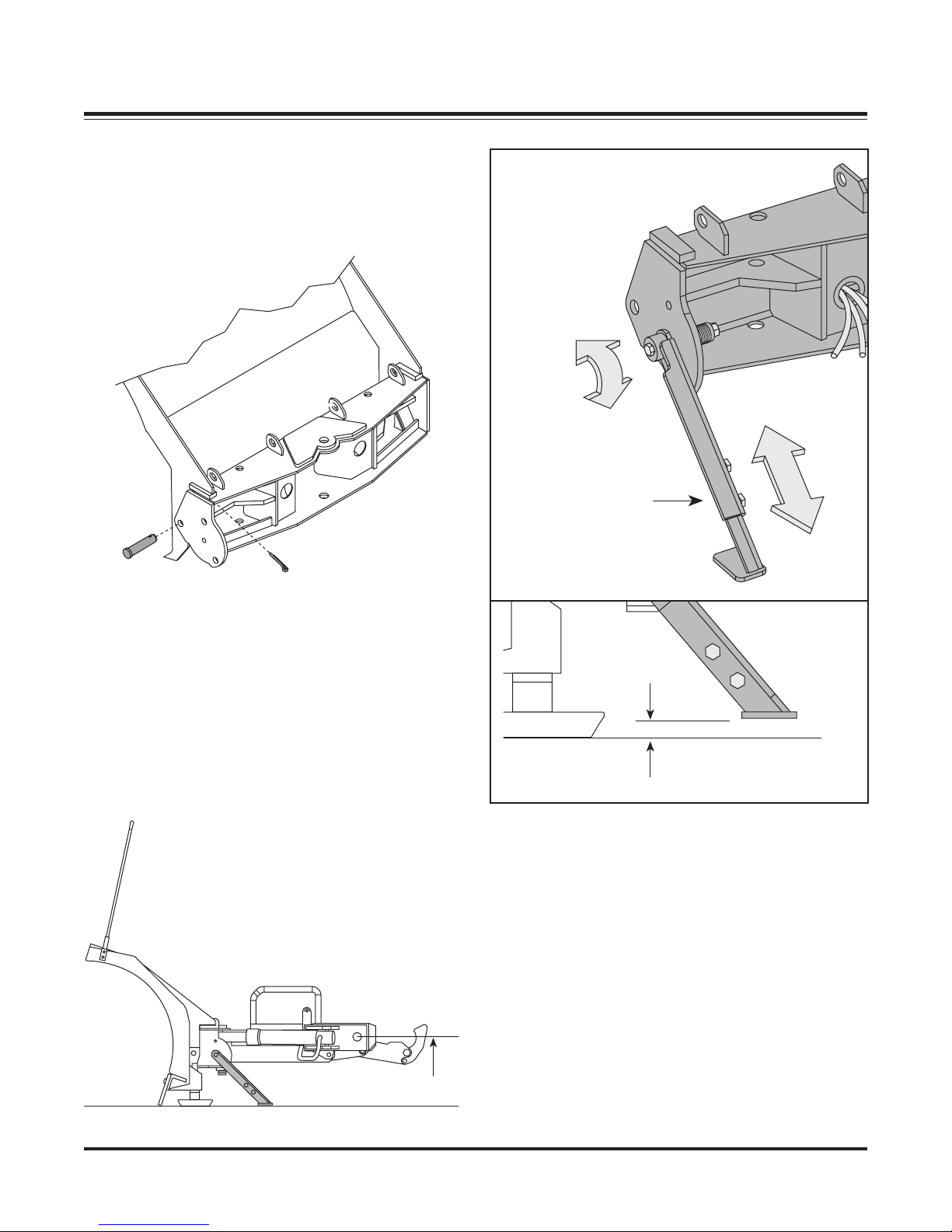
MOLDBOARD & A-FRAME ASSEMBLY
1. Position the pivot beam and A-frame near the
connecting points at the rear of the blade between
the two center support ribs. Insert one
3/4" DIA. x 3" clevis pin through each mounting
hole and secure with 1/4" DIA. x 1-1/2" cotter pin.
Spring Loaded
Adjustable
Pivot Beam
Kickstand
2. Mount the kickstand to the end of the pivot beam
(driver side) using the 1/2"-13 x 4-1/2" bolt
provided. The spring, bushing and locknut are
located on the inside of the pivot beam. Review
the diagrams below and to the right. To pivot the
kickstand, pull the spring loaded leg out and rotate
it until the pin locks into place. Adjust the foot on
the stand arm so that the foot is 1/8" from the
ground when the A-frame is level and the A-frame
mount points are 12-1/2" from the ground. Tighten
both of the locknuts on the kickstand.
1/8" Ground
Clearance
Lit. No. B64090, Rev. 00 11 April 1, 2006
12-1/2"
MOLDBOARD & A-FRAME ASSEMBLY
3. Position each angle cylinder with the rod end of
the cylinder in the pivot beam and the hydraulic
hose port facing away from the A-frame. Secure
the cylinder to the pivot beam with a 3/4" x 5"
clevis pin (B41051) and a 1/4" x 1-1/2" cotter pin
(B61357). Extend each cylinder rod until the
cylinder base mounting hole aligns with the hole
on the A-frame angle cylinder bracket. Insert
another clevis pin and secure it with a cotter pin.
4. Remove the dust cap from both of the hydraulic
angle cylinder ports and attach one
9/16"-18 x 9/16"-18 90° adjustable elbow O.R.B.
adapter (B60005) to each port. Each adapter
should be angled toward the top of the moldboard.
Connect one 3/8" x 24" hydraulic hose (B60091)
to each angle cylinder adapter. Be careful not to
over tighten the hose connections. Route both
hoses over the TOP of each cylinder. This will
prevent them from hanging or being pinched.
Tighten fittings and hoses per torque chart.
5. Remove the plastic dust caps from the hydraulic
lift cylinder ports. Attach one 9/16"-18 x 9/16"-18
45° adjustable elbow O.R.B. adapter (B60272) to
the driver’s side port (base end) and one
9/16"-18 x 9/16"-18 male O.R.B. connector
adapter (B60007) to the passenger’s side port
(rod end). Once the adapters have been installed
on the cylinder, connect the hydraulic hoses.
Tighten fittings and hoses per torque chart.
NOTE: Position the 45° fitting in the cylinder port
so that the hoses install directly in the center of
the A-frame access holes. A hose installed too
close to the edge of the opening may work itself
free with the operation of the lift cylinder and/or
movement of the plow.
The 45° adapter receives a 3/8" x 17" hydraulic
hose (B60273). Connect the 45° angle on the
hose to the hydraulic adapter on the cylinder. The
male connector adapter receives a 3/8" x 15"
hydraulic hose (B60274). Connect the 45° end of
the hose to the hydraulic adapter on the cylinder.
Both hoses should be routed through the
triangular openings in the A-frame. Tighten fittings
and hoses per torque chart.
9/16
- Manifold Port #2
B60006
- Manifold Ports #3 & 4
B60072
9/16
9/16
B60005
- Manifold Port #1
9/16
9/16
9/16
B60007
- Manifold Ports #3 & 4
- Lift Cylinder Rod End
9/16
9/16
9/16
B60272
- Lift Cylinder Base End
9/16
- Angle Cylinders
April 1, 2006 12 Lit. No. B64090, Rev. 00
MOLDBOARD & A-FRAME ASSEMBLY
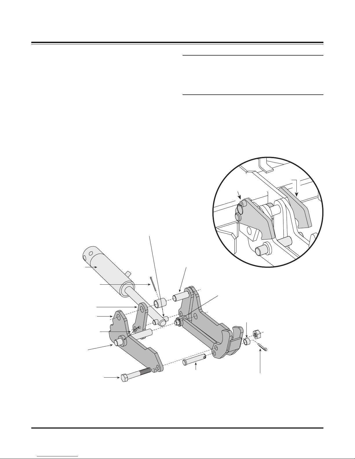
6. Remove the draw latch mount pin, spacer & cotter
pin from the draw latch assembly. By removing
this pin, the inner draw latch plates can swing free.
Remove the inner draw latch plate lift cylinder
mount pin. Position the plates on either side of the
lift/lower cylinder rod and insert the pin through the
plates and cylinder rod. With the cylinder
connected to the inner draw latch plates, rotate
the draw latch assembly toward the draw latch
mount holes on the A-frame. Align the holes in the
outer draw latch plate with those of the inner draw
latch plates and the A-frame.
Inner Draw Latch Plate
Lift Cylinder Mount Pin
3/4" x 2-1/2" or
5/8" x 2-3/8" (760LT only)
NOTE: The A-frame latch, located at the rear/center
of the A-frame, should be raised up to insert the
draw latch mount pin. Pull the A-frame latch pull
pin out and rotate the latch counterclockwise if it
is locked into position.
Secure the assembly to the A-frame by replacing
the draw latch mount pin, spacer and cotter pin.
Reset the A-frame latch so the A-frame latch pull
pin locks into place.
A-Frame
A-Frame
Latch Lock Pin
Latch
Hydraulic
Lift/Lower Cylinder
3/16" x 2-1/2"
Cotter Pin
Inner Draw Latch Plate
Outer Draw Latch Plate
3/16" x 2-1/2"
Cotter Pin
Draw Pin
1" x 6-1/2" or
1" x 5-5/8" for 760LT only
Hex Head Cap Screw
3/4"-10 x 4-1/2" or
3/4"-10 x 4" for 760LT only
Draw Latch Mount Pin
1" x 4-21/32" or
1" x 3-7/8" (760LT only)
Draw Latch Arm Pivot Pin
3/4" x 2-1/2" or
3/4" x 2-3/8" for 760LT only
1" O.D. x 25/32" I.D. x 5/8"
Clevis Pin
3/4" x 3-41/64" or
3/4" x 3-7/16" for 760LT only
Spacer
1/4" x 1-1/2"
Cotter Pin
Lit. No. B64090, Rev. 00 13 April 1, 2006
MOLDBOARD & A-FRAME ASSEMBLY
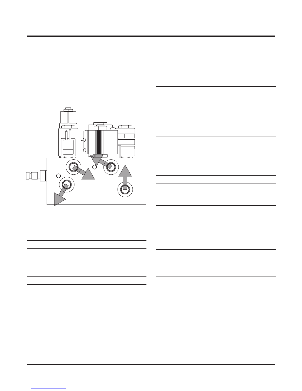
7. Assemble the manifold. The manifold, pump and
coil harness have been connected at the factory;
however, the manifold contains several
components that you will need to install prior to
securing the assembly to the A-frame. Each of the
hose ports on the manifold is covered with stretch
wrap. Remove the wrap and install the appropriate
fitting in its respective port. Tighten fittings and
hoses per torque chart.
32
1
4
8. Align the mount holes in the pump with the holes
in the hinged bracket, located on the A-frame.
NOTE: Before mounting the pump, angle the
hinged bracket as needed and tighten the bracket
hardware to lock it in place.
Secure with 3/8"-16 x 3/4" hex head cap screw and
3/8" flat washer through the top mount hole in the
bracket and into the pump. Insert 3/8"-16 x 1-3/4"
threaded stud with 3/8"-16 locknut through the
bottom mount hole in the bracket and into the pump.
The threaded stud should bottom out in the pump.
NOTE: When installing the manifold between the
mount brackets on the A-frame, hold the manifold
at the sides of the block. Never handle the
manifold by coils. Doing so can cause a solenoid
cartridge to bend, causing the cartridge to stick
when activated.
NOTE: A medium strength thread-locking
compound should be used on both of the pump
mount fasteners.
NOTE: The arrows shown on the manifold
illustration indicate the direction the 90° adapters
should be positioned to receive the hydraulic
hoses.
NOTE: DO NOT let any foreign objects enter into
the open ports. The valves can become
contaminated and greatly hinder the plow’s
performance. Torque to proper specifications.
NOTE: All ports are identified by a stamped
number on the manifold. The numbers also
identify the hydraulic functions, which can be
referenced on the label under the hydraulic pump
and manifold cover.
9. Connect the hydraulic hoses to their respective
adapters on the manifold. Hose P/N B60091
Ports #1 & #2, Hose P/N B60273 Port #3 and
Hose P/N B60274 Port #4. Tighten hoses per
torque chart.
NOTE: Both lift cylinder hoses should be routed
through the triangular openings in the A-frame.
Position these hoses over the A-frame angle and to
their respective manifold ports.
April 1, 2006 14 Lit. No. B64090, Rev. 00
MOLDBOARD & A-FRAME ASSEMBLY
10. Secure the manifold to the A-frame. Remove the
washers, split lock washers and cap screws from
the manifold and align the mount holes with the
A-frame brackets. Properly replace and tighten all
hardware.
Apply
Thread-Locking
Compound
11. Hook each extension spring to the receiving holes
on the pivot beam and attach the opposite end of
the spring to its respective spade bolts. Install the
spade bolts through the extension spring mounting
angle on the top rear of the blade. Secure each
spade bolt by placing one 5/8" flat washer on the
bolt and thread one 5/8"-11 nylon insert lock nut.
Tighten each lock nut until a piece of paper can
pass between the 3rd & 4th coils on the spring.
Apply
Thread-Locking
Compound
NOTE: A medium strength thread-locking
compound should be used to secure the manifold
mount fasteners.
12. Install the blade guides at each end of the
moldboard. Insert the cap screw through the holes
at the top of the wing reinforcement rib. Tighten all
screws with locknuts.
Lit. No. B64090, Rev. 00 15 April 1, 2006
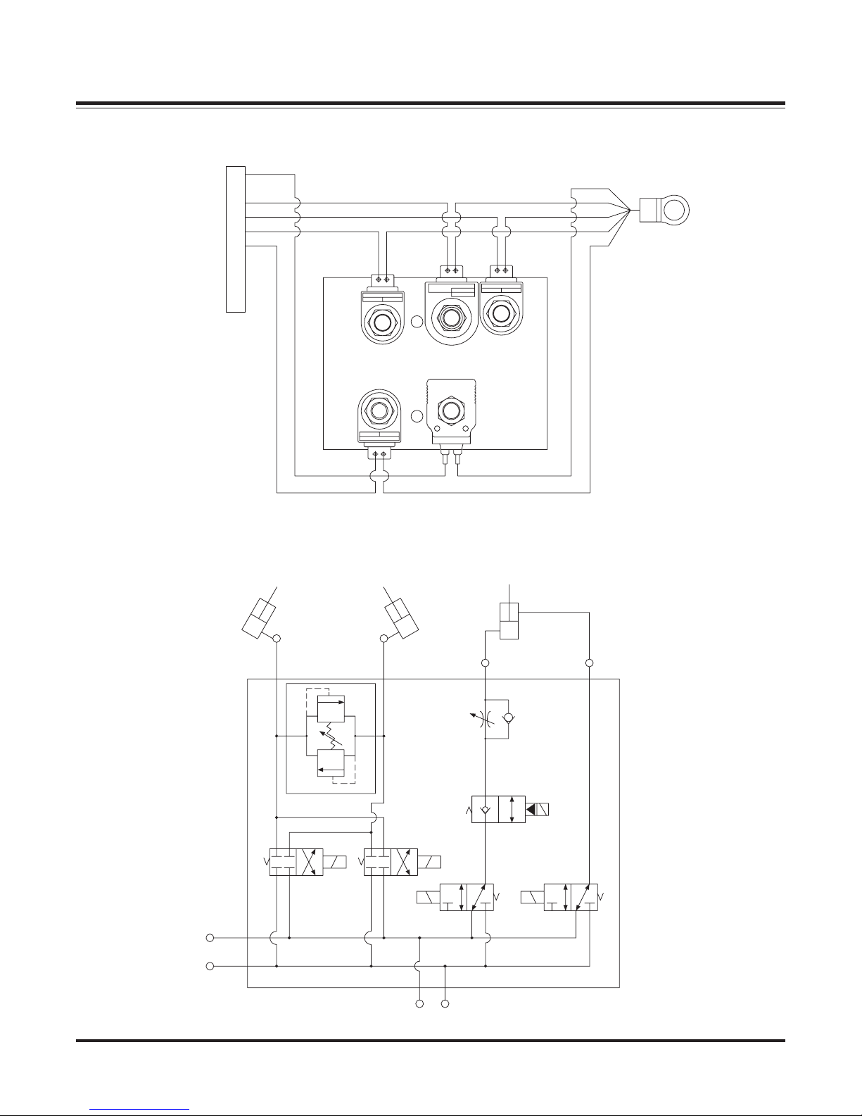
GENERAL SYSTEM SCHEMATICS
B60270 ELECTRICAL SCHEMATIC
S5
A
B
S6
C
S8
D
S4
E
S3
F
G
H
J
K
S4
S6
S8
S3
S5
B60270 HYDRAULIC SCHEMATIC
RIGHT ANGLE
LEFT ANGLE
1
3000 PSI
2
RV
3
RAISE
LIFT CYL.
LOWER
FC
4
TGP
PGP
April 1, 2006 16 Lit. No. B64090, Rev. 00
S3
S4
T1 P1
S5
S6
S8
 Loading...