

Page 1
Blizzard Lighting, LLC
www.blizzardlighting.com
Waukesha, WI USA
Copyright (c) 2015
Page 2

TABLE OF CONTENTS
Laser Blade™ G 1
1. Getting Started 3
What’s In The Box? 3
Getting It Out Of The Box 3
Powering Up! 3
Getting A Hold Of Us 3
Safety Instructions (Don’t Stick Your Hand In The Toaster!) 4
2. Meet The Laser Blade™ G 5
Main Features 5
DMX Quick Reference 5
The Laser Blade™ G Pin-up Picture 6
3. Setup 7
Fuse Replacement 7
Connecting A Bunch Of Laser Blade™ G Fixtures 7
Data/DMX Cables 7
Cable Connectors 8
3-Pin??? 5-Pin??? Huh? 8
Take It To The Next Level: Setting up DMX Control 8
Fixture Linking (Master/Slave Mode) 9
Mounting/Rigging 9
4. Operating Adjustments 10
Navigating The Control Panel 10
Control Panel Menu Structure 11
DMX Mode 11
Set The Starting DMX Address 11
Working Mode Settings 11
DMX, Auto, & Sound Active Mode 11
Slave Mode 11
Mirror Symmetry Mode 12
Running Mode Settings 12
Graphic Mode Settings 12
Speed Settings 12
DMX Channel Values In-Depth 13
Troubleshooting 14
5. Appendix 15
A Quick DMX Lesson 15
Keeping Your Laser Blade™ G As Good As New 16
Returns (Gasp!) 16
Shipping Issues 16
Tech Specs 17
Laser Blade™ G User Manual Rev. A © Copyright 2015 Blizzard Lighting, LLC
Page 2
Page 3

1. GETTING STARTED
What’s In The Box?
• 1 x Laser Blade™ G Moving Head Fixture
• 1 x Ever-So-Handy Power Cord
• This Lovely User Manual
Getting It Out Of The Box
Congratulations! You are ready to put on a totally stellar green laser light show with your
way cool, super-sharp moving head Laser Blade™ G! So now that you’ve got your new
Laser Blade™ G (or hopefully, GEEZ!), you should carefully unpack the box and check the
contents to ensure that all parts are present and in good condition. If anything looks as if it
has been damaged in transit, notify the shipper immediately and keep the packing material
for inspection. Again, please save the carton and all packing materials. If a xture must
be returned to the factory, it is important that the xture be returned in the original factory
box and packing.
Powering Up!
All xtures must be powered directly off a switched circuit and cannot be run off a
rheostat (variable resistor) or dimmer circuit, even if the rheostat or dimmer
channel is used solely for a 0% to 100% switch.
AC Voltage Switch - Not all xtures have a voltage select switch, so please verify that the
xture you receive is suitable for your local power supply. See the label on the xture or
refer to the xture’s specications chart for more information. A xture’s listed current
rating is its average current draw under normal conditions. Check the xture or device
carefully to make sure that if a voltage selection switch exists that it is set to the correct
line voltage you will use.
Warning! Verify that the voltage select switch on your unit matches the line
voltage applied. Damage to your xture may result if the line voltage applied does
not match the voltage indicated on the voltage selector switch. All xtures must
be connected to circuits with a suitable Ground (Earthing).
Getting A Hold Of Us
If something happens goes wrong, please visit www.blizzardlighting.com/
support and open a support ticket. We’ll be happy to help, honest.
Blizzard Lighting
N24 W23750 Watertown Rd. Suite B
Waukesha, WI 53188 USA
www.blizzardlighting.com
Disclaimer: The information and specications contained in this document are subject
to change without notice. Blizzard Lighting™ assumes no responsibility or liability for any
errors or omissions that may appear in this user manual. Blizzard Lighting™ reserves the
right to update the existing document or to create a new document to correct any errors
or omissions at any time. You can download the latest version of this document from www.
blizzardlighting.com.
Author: Date: Last Edited: Date:
J. Thomas 11/16/2015 J. Thomas 11/16/2015
Laser Blade™ G User Manual Rev. A © Copyright 2015 Blizzard Lighting, LLC
Page 3
Page 4
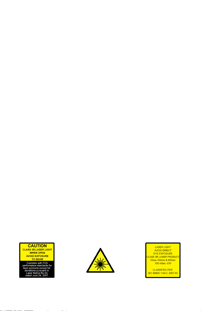
LASER SAFETY REQUIREMENTS
Lasers are one of the coolest effects available, and when they are used appropriately, they will be fun, legal and harmless. To make sure that is the case...
• Always set up and install all laser effects so that all laser light is at least 3 me-
ters (9.8 feet) above the oor on which people can stand.
• After setting up, and before public use, test laser to ensure proper function. Do
not use if any defect is detected. Do not use if laser emits only one or two laser
beams rather than dozens/hundreds, as this could indicate damage to the diffraction grating optic, and could allow emission of higher laser levels above Class
3R.
• NEVER point lasers at people or animals. Never look into the laser aperture or
laser beams.
• NEVER point lasers in areas in which people can potentially get exposed, such
as uncontrolled balconies, etc.
• NEVER point lasers at highly reective surfaces, such as windows, mirrors and
shiny metal. Even laser reections can be hazardous.
• NEVER point a laser at aircraft, this is a federal offense!
• NEVER point un-terminated laser beams into the sky.
• NEVER expose the output optic (aperture) to cleaning chemicals.
• NEVER use laser if the laser appears to emit only one or two beams.
• NEVER use the laser if the housing is damaged, the housing is open, or if the
optics appear damaged in any way.
• NEVER open the laser housing. The high laser power levels inside of the pro-
tective housing can start res, burn skin and will cause instant eye injury.
• NEVER leave this device running unattended.
The operation of a class 3R laser show is only allowed if the show is controlled
by a skilled and well-trained operator, familiar with the data from this manual.
The legal requirements for using laser entertainment products vary from country
to country. The user is responsible for the legal requirements at the location/
country of use.
Laser Blade™ G User Manual Rev. A © Copyright 2015 Blizzard Lighting, LLC
Page 4
Page 5
2. MEET THE LASER BLADE™ G
MAIN FEATURES
• 50mW, 532nm green DPSS CLASS 3R fat beam laser
• 15KPPS galvo scanners
• Moving head features 540º pan & 270º tilt
• 133 built-in geometric gures, 14 animations, & 76 beam patterns
• Easy-to-use 4-button LCD control panel menu
• Built-in auto-beam, auto-animation and sound-activate programs
• 2 animations in one frame can be operated separately via DMX
• Perfect for venues, large and small
• Ready to use right out of the box
ADDITIONAL FEATURES
• Rugged and well-built (It hits the gym regularly)
• Lightweight and easily portable
• Clamp mounting bracket included
• IEC power input connector
• Easy-to-use 4-button LCD control panel
• 3-pin DMX input and output
DMX Quick Reference
Channel 18-Channel
1 Mode Selection, DMX/Auto/Sound
2 Pan
3 Tilt
4 Vertical Speed (Slow <--> Fast)
5 Group 1, Pattern Selection
6 Group 1, OFF/ON
7 Group 2, Pattern Selection
8 Group 2, OFF/ON
9 2 Groups Animation
10 Moving-X
11 Moving-Y
12 X-Axis Rotation
13 Y-Axis Rotation
14 Rotation
15 Zoom In/Out
16 Sine Wave Fluctuation
17 Fluctuation Speed
18 Auto Dot (Slow <--> Fast)
Laser Blade™ G User Manual Rev. A © Copyright 2015 Blizzard Lighting, LLC
Page 5
Page 6

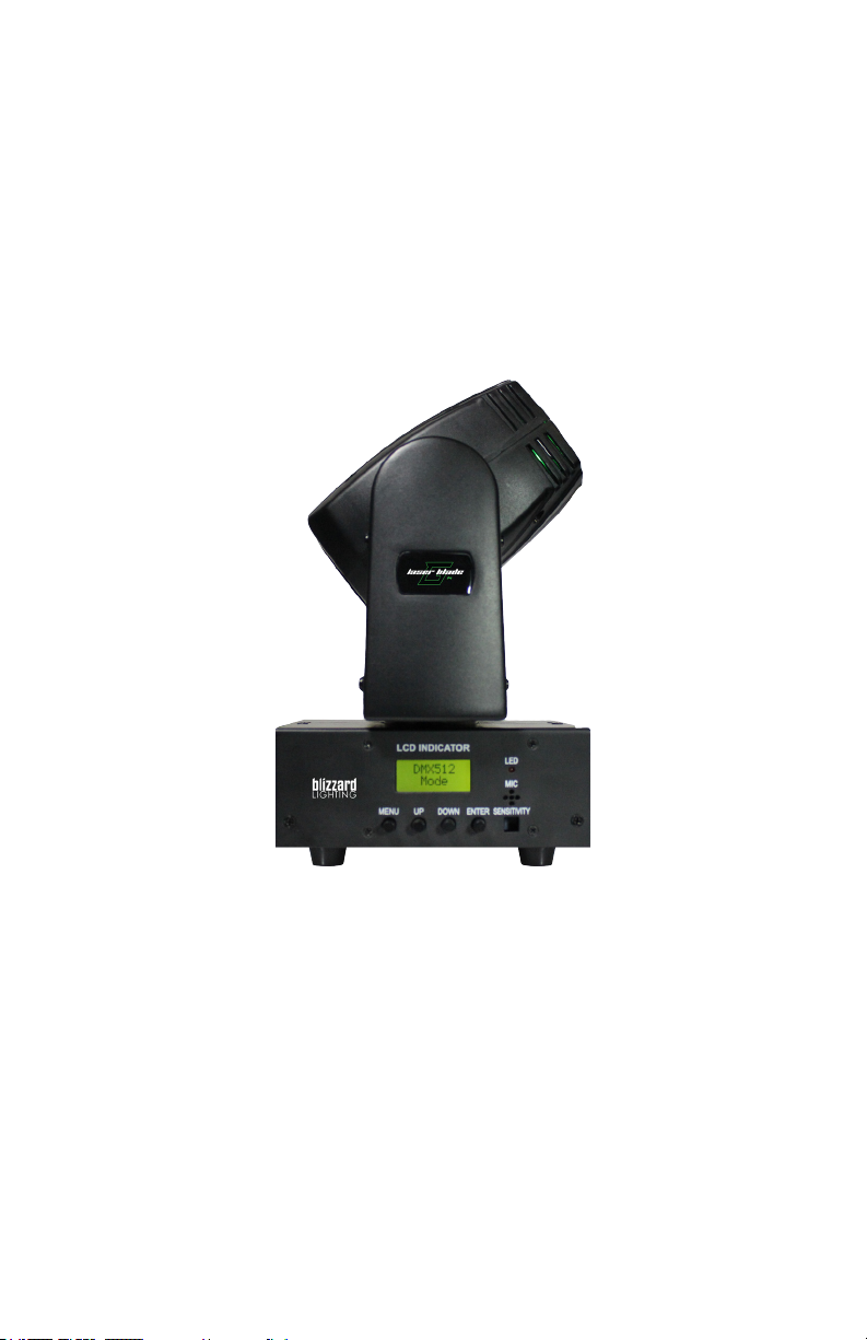
Figure 1: The Laser Blade™ G Pin-Up Picture
Head/Arms
Base
4-Button
LCD Control
Panel
Figure 2: The Rear Connections
Laser Output
(Aperture)
DMX Signal
Indicator
Microphone
Mic Sensitivity
Adjustment
DMX Input
AC Power
Input
DMX Output
Power
Switch
Laser Blade™ G User Manual Rev. A © Copyright 2015 Blizzard Lighting, LLC
Page 6
Page 7

3. SETUP
Fuse Replacement
With a at head screwdriver, wedge the
fuse holder out of its housing. Remove the
damaged fuse from its holder and replace
with exact same type fuse (2A, 250V).
Insert the fuse holder back in its place and
reconnect power.
Connecting A Bunch of Laser Blade™ G Fixtures
You will need a serial data link to run light shows using a DMX-512
controller or to run shows on two or more xtures set to sync in master/slave operating mode. The combined number of channels required
by all the xtures on a serial data link determines the number of xtures the data link can support.
Fixtures on a serial data link must be daisy chained in one single line.
Also, connecting more than 32 xtures on one serial data link without
the use of a DMX optically-isolated splitter may result in deterioration
of the digital DMX signal.
The maximum recommended cable-run distance is 500 meters (1640
ft). The maximum recommended number of xtures on a serial data
link is 32 xtures.
Data/DMX Cabling
To link xtures together you’ll need data cables. You should use data-
grade cables that can carry a high quality signal and are less prone to
electromagnetic interference.
For instance, Belden© 9841 meets the specications for EIA RS-485
applications. Standard microphone cables will “probably” be OK, but
note that they cannot transmit DMX data as reliably over long distances. In any event, the cable should have the following characteristics:
2-conductor twisted pair plus a shield
Maximum capacitance between conductors – 30 pF/ft.
Maximum capacitance between conductor & shield – 55 pF/ft.
Maximum resistance of 20 ohms / 1000 ft.
Nominal impedance 100 – 140 ohms
Laser Blade™ G User Manual Rev. A © Copyright 2015 Blizzard Lighting, LLC
Page 7
Page 8

Cable Connectors
Cables must have a male XLR connector on one end and a female XLR
connector on the other end. (Duh!)
CAUTION: Do not allow contact between the common and the x-
ture’s chassis ground. Grounding the common can cause a ground
loop, and your xture may perform erratically. Test cables with an
ohm meter to verify correct polarity and to make sure the pins are not
grounded or shorted to the shield or each other.
3-Pin??? 5-Pin??? Huh?!?
If you use a controller with a 5 pin DMX output connector, you will need to use a 5 pin to 3 pin adapter.
They are widely available over the internet and from specialty retailers If you’d like to build your own, the
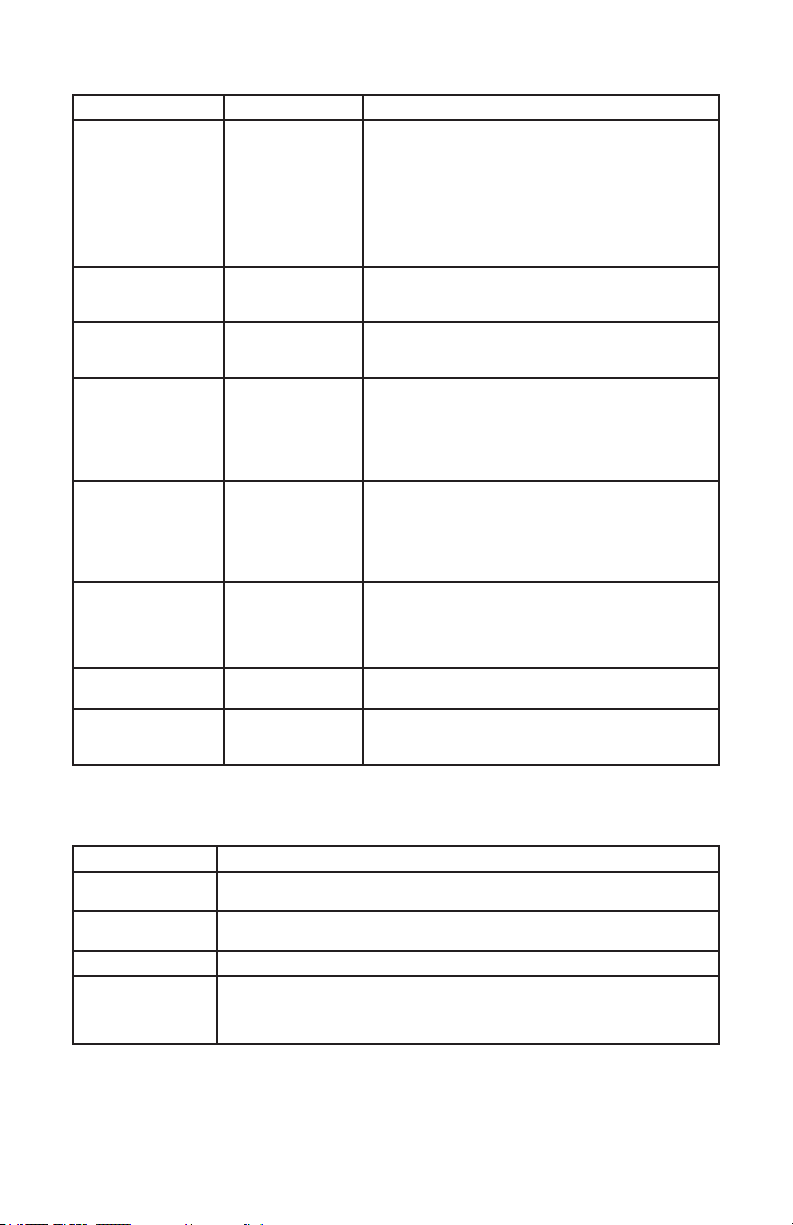
chart below details a proper cable conversion:
Conductor 3-Pin Female
(Output)
5-Pin Male
(Input)
Ground/Shield Pin 1 Pin 1
DMX Data (-) Pin 2 Pin 2
DMX Data (+) Pin 3 Pin 3
Not Used. No Connection. No Connection.
Not Used. No Connection. No Connection.
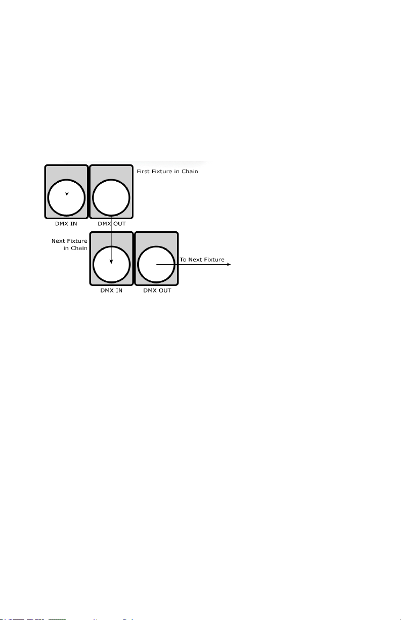
Take It To The Next Level: Setting Up DMX Control
Step 1: Connect the male connector of the
DMX cable to the female connector (output)
on the controller.
Step 2: Connect the female connector of the
DMX cable to the rst xture’s male connector (input). Note: It doesn’t matter which
xture address is the rst one connected.
We recommend connecting the xtures in
terms of their proximity to the controller,
rather than connecting the lowest xture
number rst, and so on.
Step 3: Connect other xtures in the chain
from output to input as above. Place a DMX
terminator on the output of the nal xture
to ensure best communication.
Laser Blade™ G User Manual Rev. A © Copyright 2015 Blizzard Lighting, LLC
Page 8
Page 9
Fixture Linking (Master/Slave Mode)
1. Connect the (male) 3 pin connector side of the
DMX cable to the output (female) 3 pin connector of
the rst xture.
2. Connect the end of the cable coming from the
rst xture which will have a (female) 3 pin connector to the input connector of the next xture con-
sisting of a (male) 3 pin connector. Then, proceed
to connect from the output as stated above to the
input of the following xture and so on.
A quick note: Often,
the setup for MasterSlave and Standalone
operation requires that
the rst xture in the
chain be initialized for
this purpose via either
settings in the control
panel or DIP-switches.
Secondarily, the xtures
that follow may also require a slave setting.
Check the “Operating Adjustments” section in this manual for com-
plete instructions for this type of setup and conguration.
Mounting & Rigging
This xture may be mounted in any SAFE position provided there is
enough room for ventilation.
It is important never to obstruct the fan or vents pathway. Mount the
xture using a suitable “C” or “O” type clamp. The clamp should be
rated to hold at least 10x the xture’s weight to ensure structural sta-
bility. Do not mount to surfaces with unknown strength, and ensure
properly “rated” rigging is used when mounting xtures overhead.
Adjust the angle of the xture by loosening both knobs and tilting the
xture. After nding the desired position, retighten both knobs.
• When selecting installation location, take into consideration lamp
replacement access (if applicable) and routine maintenance.
• Safety cables MUST ALWAYS be used.
Laser Blade™ G User Manual Rev. A © Copyright 2015 Blizzard Lighting, LLC
Page 9
Page 10

4. OPERATING ADJUSTMENTS
The Control Panel
All the goodies and different modes possible with the Laser Blade™
G are accessed by using the control panel on the front of the xture.
There are 4 control buttons below the LED display which allow you to
navigate through the various control panel menus.
<MENU>
Is used to navigate to the previous higher-level menu item.
<UP>
Scrolls through menu items and numbers in ascending order.
<DOWN>
Scrolls through menu items and numbers in descending order.
<ENTER>
Is used to select and conrm/store the current selection.
The Control Panel LED Display shows the menu items you select from
the menu map on page #11. When a menu function is selected, the
display will show immediately the rst available option for the selected
menu function. To select a menu item, press <ENTER>.
Use the <UP> and <DOWN> buttons to navigate the menu options.
Press the <ENTER> button to select the menu function currently displayed, or to enable a menu option. To return to the previous option or
menu, press the <MENU> button.
Laser Blade™ G User Manual Rev. A © Copyright 2015 Blizzard Lighting, LLC
Page 10
Page 11

Control Panel Menu Structure
Address <ENTER> To choose a DMX address from 001-512
Work Mode Set Auto Auto run mode
Sound Sound active mode
DMX DMX mode
Slave Slave mode
X Mirror Set Yes/No X mirror symmetry (reverse) on/off
Y Mirror Set Yes/No Y mirror symmetry (reverse) on/off
X Run Set Run <ENTER>
Stop X Position (+/-) 1 <ENTER>
Y Run Set Run <ENTER>
Stop X Position (+/-) 1 <ENTER>
Graph Mode Set <ENTER> <UP/DOWN> to choose beams/animations
Speed Set <ENTER> <UP/DOWN> to increase/decrease speed
DMX Mode
Allows the unit to be controlled by any universal DMX controller.
Set the Starting DMX Address:
The default mode for the xture is DMX, so the rst menu item that you can edit is
the starting DMX address.
1.) Navigate the menu using the <UP/DOWN> buttons until you reach Address.
2.) Push the <ENTER> button.
3.) Use the <UP/DOWN> buttons to select a DMX channel from 001-512.
4.) Press the <ENTER> button to conrm.
Working Mode Settings:
Set the xture to run in DMX, Auto, Sound Active, and Slave Modes
1.) Navigate the menu using the <UP/DOWN> buttons until you reach Work
Mode Set.
2.) Push the <ENTER> button.
3.) Use the <UP/DOWN> buttons to select either DMX, Auto, or Sound. Then
press the <ENTER> button to conrm.
Slave Mode
1.) Daisy chain the xtures DMX in/out. The 1st xture will be the master xture.
2.) On xtures you want to set as slave xtures, navigate the menu(s) using the
<UP/DOWN> buttons until you reach Work Mode Set.
3.) Push the <ENTER> button.
4.) Use the <UP/DOWN> buttons to reach Slave. Then press <ENTER>.
Laser Blade™ G User Manual Rev. A © Copyright 2015 Blizzard Lighting, LLC
Page 11
Page 12

Mirror Symmetry Mode:
Reverse/ip the output of either X, Y, or both.
1.) Navigate the menu using the <UP/DOWN> buttons until you reach either X
Mirror Set or Y Mirror Set.
2.) Push the <ENTER> button.
3.) Use the <UP/DOWN> buttons to select Yes to enable, or No to disable.
4.) Press the <ENTER> button to conrm.
Running Mode Settings:
Fine tune the position of either X, Y, or both.
1.) Navigate the menu using the <UP/DOWN> buttons until you reach either X
Run Set or Y Run Set.
2.) Push the <ENTER> button.
3.) Use the <UP/DOWN> buttons to select Run for default, or Stop to adjust
incremental positioning.
4.) Press the <ENTER> button to conrm.
Graphic Mode Settings:
Set the xture to display graphic beams or animations.
1.) Navigate the menu using the <UP/DOWN> buttons until you reach Graph
Mode Set.
2.) Push the <ENTER> button.
3.) Use the <UP/DOWN> buttons to select Beam Show, or Animal Show to
adjust incremental positioning.
4.) Press the <ENTER> button to conrm.
Speed Settings:
Used to adjust the speed settings.
1.) Navigate the menu using the <UP/DOWN> buttons until you reach Speed
Set.
2.) Push the <ENTER> button.
3.) Use the <UP/DOWN> buttons to adjust incremental speed settings.
4.) Press the <ENTER> button to conrm.
Laser Blade™ G User Manual Rev. A © Copyright 2015 Blizzard Lighting, LLC
Page 12
Page 13

DMX Values In-Depth (19-Channel Mode)
Channel Value What It Does
1
2 000 <--> 255 Pan (0 <--> 540°)
3 000 <--> 255 Tilt (0 <--> 270°)
4 000 <--> 255 Vertical Speed (slow <--> fast)
5
6
7
8
9
10
000 <--> 063
064 <--> 127
128 <--> 191
192 <--> 255
000 <--> 001
002 <--> 220
221 <--> 227
228 <--> 229
230 <--> 231
232 <--> 233
234 <--> 235
236 <--> 237
238 <--> 239
240 <--> 241
242 <--> 243
244 <--> 245
246 <--> 247
248 <--> 249
250 <--> 251
252 <--> 255
000 <--> 015
016 <--> 255
000 <--> 028
029 <--> 255
000 <--> 015
016 <--> 255
000 <--> 020
021 <--> 041
042 <--> 062
063 <--> 083
084 <--> 104
105 <--> 125
126 <--> 146
147 <--> 167
168 <--> 188
189 <--> 209
210 <--> 230
231 <--> 251
252 <--> 255
000 <--> 127
128 <--> 160
162 <--> 192
193 <--> 224
225 <--> 239
240 <--> 247
248 <--> 255
Run Mode
No function (laser is off)
Sound active mode
Auto mode
DMX mode
Group 1, Pattern Selection
No function (laser is off)
133 geometric animations
Screen theme animation
Wedding y wing to wing animation
Halloween theme animation 1
Halloween theme animation 2
Congratulations theme animation
Christmas theme animation
Happy birthday theme animation
Lightning
Pole dance
Dancing
Musical notes
Fish big splash
Trees
Drum beating
Group 1 On/Off
Laser off
Laser on
Group 2, Pattern Selection
No function (laser is off)
76 kinds of beam patterns
Group 2 On/Off
Laser off
Laser on
Dual Group Animations
Single animation (group 1)
X mirror symmetry
Y mirror symmetry
X/Y mirror symmetry, simultaneously
Zoom In/Out, mirror symmetry
Group 2 pattern left/right moving, group 1 stationary
Group 2 pattern zoom in/out, group 1 stationary
Group 2 pattern rotate, group 1 stationary
Rotation mirror symmetry
Group 1 no Y moving, group 2 no X moving
Group 1 no X/Y moving, but group 2 X/Y moving
Group 1 no Y dimmer, group 2 no X dimmer
Group 1 no X moving, group 2 no Y moving
Moving X
Manual to left/right moving
Auto to left moving
Auto to right moving
Auto to left/right moving
Jumping
Rhombus shape moving
Top left/right moving
Laser Blade™ G User Manual Rev. A © Copyright 2015 Blizzard Lighting, LLC
Page 13
Page 14
DMX Values In-Depth (19-Channel Mode), Continued
Channel Value What It Does
11
12
13
14
15
16
17
18
000 <--> 127
128 <--> 160
162 <--> 192
193 <--> 224
225 <--> 231
232 <--> 239
240 <--> 247
248 <--> 255
000 <-> 127
128 <-> 255
000 <-> 127
128 <-> 255
000 <--> 127
128 <--> 159
160 <--> 191
192 <--> 223
224 <--> 255
000 <--> 127
128 <--> 159
160 <--> 191
192 <--> 223
224 <--> 255
000 <--> 063
064 <--> 127
128 <--> 191
192 <--> 255
000 <--> 255
000 <-> 063
064 <-> 255
Moving Y
Manual to up/down moving
Auto to down moving
Auto to up moving
Auto to up/down moving
Circle shape moving
Sine shape moving
Square shape moving
Bottom corner up/down moving
X-Axis Rotation
Manual Position
Auto Position Spin
X-Axis Rotation
Manual Position
Auto Position Spin
Rotation
Manually rotation
Auto clockwise rotation
Auto counter clockwise rotation
Clock pendulum effect
Ellipse shape rotation
Zoom
No Function
Manual zoom(+/-)
Auto zoom(+)
Auto zoom(-)
Auto zoom(+/-)
Sine Wave Fluctuation
No Function
X uctuation
Y uctuation
X/Y uctuation
Fluctuation Speed
Speed adjustment (slow <-- fast)
Drawing
Manual Draw
Auto Draw (slow <--> fast)
Troubleshooting
Symptom Solution
Fixture Auto-Shut
Off
No Light Output Check to ensure xture is operating under correct mode, IE DMX/Etc., if ap-
No Power Check fuse, AC cord and circuit for malfunction.
Fixture Not Responding / Responding
Erratically
please open a support ticket at www.blizzardlighting.com/support.
Laser Blade™ G User Manual Rev. A © Copyright 2015 Blizzard Lighting, LLC
Please check the power supply, the input voltage and the fuse.
plicable.
Make sure all connectors are seated properly and securely.
Use Only DMX cables and/or check cables for defects.
Install a Terminator.
Reset xture(s).
If your problem isn’t listed, or if problems persist,
Page 14
Page 15

5. APPENDIX
A Quick Lesson On DMX
DMX (aka DMX-512) was created in 1986 by the United States Institute for Theatre
Technology (USITT) as a standardized method for connecting lighting consoles to lighting
dimmer modules. It was revised in 1990 and again in 2000 to allow more exibility. The
Entertainment Services and Technology Association (ESTA) has since assumed control over
the DMX512 standard. It has also been approved and recognized for ANSI standard clas-
sication.
DMX covers (and is an abbreviation for) Digital MultipleXed signals. It is the most common
communications standard used by lighting and related stage equipment.
DMX provides up to 512 control “channels” per data link. Each of these channels was originally intended to control lamp dimmer levels. You can think of it as 512 faders on a lighting
console, connected to 512 light bulbs. Each slider’s position is sent over the data link as an
8-bit number having a value between 0 and 255. The value 0 corresponds to the light bulb
being completely off while 255 corresponds to the light bulb being fully on.
DMX data is transmitted at 250,000 bits per second using the RS-485 transmission standard over two wires. As with microphone cables, a grounded cable shield is used to prevent
interference with other signals.
There are ve pins on a DMX connector: a wire for ground (cable shield), two wires for
“Primary” communication which goes from a DMX source to a DMX receiver, and two wires
for a “Secondary” communication which goes from a DMX receiver back to a DMX source.
Generally, the “Secondary” channel is not used so data ows only from sources to receivers. Hence, most of us are most familiar with DMX-512 as being employer over typical
3-pin “mic cables,” although this does not conform to the dened standard.
DMX is connected using a daisy-chain conguration where the source connects to the input
of the rst device, the output of the rst device connects to the input of the next device,
and so on. The standard allows for up to 32 devices on a single DMX link.
Each receiving device typically has a means for setting the “starting channel number” that
it will respond to. For example, if two 6-channel xtures are used, the rst xture might
be set to start at channel 1 so it would respond to DMX channels 1 through 6, and the next
xture would be set to start at channel 7 so it would respond to channels 7 through 12.
The greatest strength of the DMX communications protocol is that it is very simple and
robust. It involves transmitting a reset condition (indicating the start of a new “packet”),
a start code, and up to 512 bytes of data. Data packets are transmitted continuously. As
soon as one packet is nished, another can begin with no delay if desired (usually another
follows within 1 ms). If nothing is changing (i.e. no lamp levels change) the same data will
be sent out over and over again. This is a great feature of DMX -- if for some reason the
data is not interpreted the rst time around, it will be re-sent shortly.
Not all 512 channels need to be output per packet, and in fact, it is very uncommon to nd
all 512 used. The fewer channels are used, the higher the “refresh” rate. It is possible to
get DMX refreshes at around 1000 times per second if only 24 channels are being transmitted. If all 512 channels are being transmitted, the refresh rate is around 44 times per
second.
In summary, since its design and evolution in the 1980’s DMX has become the standard
for lighting control. It is exible, robust, and scalable, and its ability to control everything
from dimmer packs to moving lights to foggers to lasers makes it an indispensable tool for
any lighting designer or lighting performer.
Laser Blade™ G User Manual Rev. A © Copyright 2015 Blizzard Lighting, LLC
Page 15
Page 16

Keeping Your Laser Blade™ G As Good As New
The xture you’ve received is a rugged, tough piece of pro lighting equipment, and as long as you take care of it, it will take care of you. That said, like
anything, you’ll need to take care of it if you want it to operate as designed.
You should absolutely keep the xture clean, especially if you are using it in an
environment with a lot of dust, fog, haze, wild animals, wild teenagers or spilled
drinks.
Cleaning the optics routinely with a suitable glass cleaner will greatly improve
the quality of light output. Keeping the fans free of dust and debris will keep
the xture running cool and prevent damage from overheating.
In transit, keep the xtures in cases. You wouldn’t throw a prized guitar,
drumset, or other piece of expensive gear into a gear trailer without a case,
and similarly, you shouldn’t even think about doing it with your shiny new light
xtures.
Common sense and taking care of your xtures will be the single biggest thing
you can do to keep them running at peak performance and let you worry about
designing a great light show, putting on a great concert, or maximizing your client’s satisfaction and “wow factor.” That’s what it’s all about, after all!
Returns (Gasp!)
We’ve taken a lot of precautions to make sure you never even have to worry
about sending a defective unit back, or sending a unit in for service. But, like
any complex piece of equipment designed and built by humans, once in a while,
something doesn’t go as planned. If you nd yourself with a xture that isn’t
behaving like a good little xture should, you’ll need to obtain a Return Authori-
zation (RA).
Don’t worry, this is easy. Just go to our website and open a support ticket at
www.blizzardlighting.com/support, and we’ll issue you an RA. Then, you’ll need
to send the unit to us using a trackable, pre-paid freight method. We suggest
using USPS Priority or UPS. Make sure you carefully pack the xture for transit,
and whenever possible, use the original box & packing for shipping.
When returning your xture for service, be sure to include the following:
1.) Your contact information (Name, Address, Phone Number, Email address).
2.) The RA# issued to you
3.) A brief description of the problem/symptoms.
We will, at our discretion, repair or replace the xture. Please remember that
any shipping damage which occurs in transit to us is the customer’s responsibility, so pack it well!
Shipping Issues
Damage incurred in shipping is the responsibility of the shipper, and
must be reported to the carrier immediately upon receipt of the items.
Claims must be made within seven (7) days of receipt.
Laser Blade™ G User Manual Rev. A © Copyright 2015 Blizzard Lighting, LLC
Page 16
Page 17

Tech Specs!
Weight & Dimensions
Length 7.1 inches (180 mm)
Width 5.5 inches (140 mm)
Height 10.6 inches (270 mm)
Weight 6.7 lbs (3 kg)
Power
Operating Voltage 110-250VAC, 50-60 Hertz
Fuse 2A 250V
Power Consumption 20W
Light Source
Laser Fat beam 50mW 532nm green DPSS
Scanner 15kpss high-speed optical scanner
Laser Class Class 3R
Thermal
Max. Operating Temp. 104 degrees F (40 degrees C) ambient
Control
Protocol USITT DMX-512
DMX Channels 18-channel
Input 3-pin XLR Male
Output 3-pin XLR Female
Other Operating Modes
Sound Active, Auto-Beam, Auto-Animation,
DMX512, Master/Slave
Other Information
Frowny wink wins for most confusing emoji ;(
Warranty 2-year limited warranty
Laser Blade™ G User Manual Rev. A © Copyright 2015 Blizzard Lighting, LLC
Page 17
Page 18

This page intentionally left blank.
Page 19

This page intentionally left blank.
Page 20
Enjoy your product!
Our sincerest thanks for your purchase!
--The team @ Blizzard Lighting
 Loading...