

Page 1
Blizzard Lighting, LLC
www.blizzardlighting.com
Waukesha, WI USA
Copyright (c) 2016
Page 2

TABLE OF CONTENTS
Kryo.Morph™ Moving Head 1
1. Getting Started 3
What’s In The Box? 3
Getting It Out Of The Box 3
Powering Up! 3
Getting A Hold Of Us 3
Safety Instructions (Don’t Stick Your Hand In The Toaster!) 4
2. Meet The Kryo.Morph™ 5
Main Features 5
Additional Features 5
DMX Quick Reference 5
The Kryo.Morph™ Pin-up Picture 6
3. Setup 7
Fuse Replacement 7
Connecting A Bunch Of Kryo.Morph™s 7
Data/DMX Cables 7
Cable Connectors 8
3-Pin??? 5-Pin??? Huh? 8
Take It To The Next Level: Setting up DMX Control 8
Fixture Linking (Master/Slave Mode) 9
Mounting/Rigging 9
Mounting Points 10
Clamp Mounting 11
Changing The Lamp 12
Lamp Adjustment 13
4. Operating Adjustments 14
The Control Panel 14
Control Panel Menu Structure 15
DMX Channel Values In-Depth 17
Gobo Replacement 23
Troubleshooting 23
5. Appendix 24
A Quick DMX Lesson 24
Keeping Your Kryo.Morph™ As Good As New 25
Returns (Gasp!) 25
Shipping Issues 25
Tech Specs 26
Dimensional Drawings 27
Kryo.Morph™ User Manual - Rev. A (c) 2016 Blizzard Lighting, LLC
Page 2
Page 3

1. GETTING STARTED
What’s In The Box?
• 1 x Kryo.Morph™ 10R Beam/Wash/Spot
• A sweet set of mounting brackets
• A groovy power cord
• This lovely user manual
Getting It Out Of The Box
Congratulations on purchasing the Kryo.Morph™, the most far-out moving head in the
galaxy with mind-blowing 3-in-1 beam/spot/wash capabilities! Now that you’ve got your
Kryo.Morph™ (or hopefully, Morphs!) you should carefully unpack the box and check the
contents to ensure that all parts are present and in good condition. If anything looks as if it
has been damaged in transit, notify the shipper immediately and keep the packing material
for inspection. Again, please save the carton and all packing materials. If a xture must
be returned to the factory, it is important that the xture be returned in the original factory
box and packing.
Powering Up!
All xtures must be powered directly off a switched circuit and cannot be run off a
rheostat (variable resistor) or dimmer circuit, even if the rheostat or dimmer
channel is used solely for a 0% to 100% switch.
AC Voltage Switch - Not all xtures have a voltage select switch, so please verify that the
xture you receive is suitable for your local power supply. See the label on the xture or
refer to the xture’s specications chart for more information. A xture’s listed current
rating is its average current draw under normal conditions. Check the xture or device
carefully to make sure that if a voltage selection switch exists that it is set to the correct
line voltage you will use.
Warning! Verify that the voltage select switch on your unit matches the line
voltage applied. Damage to your xture may result if the line voltage applied does
not match the voltage indicated on the voltage selector switch. All xtures must
be connected to circuits with a suitable Ground (Earthing).
Getting A Hold Of Us
If something is wrong, please just visit our website at www.blizzardlighting.com/
support and open a support ticket. We’ll be happy to help, honest.
Blizzard Lighting
N24 W23750 Watertown Rd Suite B
Waukesha, WI 53188 USA
www.blizzardlighting.com
414-395-8365
Disclaimer: The information and specications contained in this document are subject
to change without notice. Blizzard Lighting™ assumes no responsibility or liability for any
errors or omissions that may appear in this user manual. Blizzard Lighting™ reserves the
right to update the existing document or to create a new document to correct any errors
or omissions at any time. You can download the latest version of this document from www.
blizzardlighting.com.
Author: Date: Last Edited: Date:
J. Thomas 1/31/2016 J. Thomas 2/8/2016
Kryo.Morph™ User Manual - Rev. A (c) 2016 Blizzard Lighting, LLC
Page 3
Page 4

SAFETY INSTRUCTIONS
• This xture falls under protection class I, this xture must be earthed!
• This product is intended for indoor use only.
• Make sure that you are connecting to the proper voltage, and that the line voltage you are
connecting to is not higher than that stated on the decal or rear panel of the xture.
• Avoid direct eye exposure to the light source while it is on.
• To prevent risk of re or shock, do not expose xture to rain or moisture.
• The minimum distance between light output and the illuminated surface must be more
than 10 meters (32.8 FT).
• Do not touch the device’s housing bare hands during its operation (housing becomes hot).
Allow the xture to cool approximately 20 minutes.
• If the xture has been exposed to drastic temperature uctuation (e.g. after transporta-
tion), do not switch it on immediately. The arising condensation water might damage your
device. Leave the device switched off until it has reached room temperature.
• During the initial start-up some smoke or smell may arise. This is a normal process and
does not necessarily mean that the device is defective.
• The lamp has to be replaced when it is damaged or deformed due to the heat. Fast on-offcycles (e.g. 10 min. on/10 min. off) will reduce lamp life.
• Always disconnect the xture from AC power before cleaning, removing or installing the
fuses, or any part.
• For replacement use lamps and fuses of same type and rating only.
• Make sure there are no ammable materials close to the unit while operating.
• The unit must be installed in a location with adequate ventilation, at least 20in (50cm)
from adjacent surfaces. Be sure that no ventilation slots are blocked.
• ALWAYS secure xture using a safety chain. Use its carrying handles while transporting.
• DO NOT operate at ambient temperatures higher than 104°F (40°C).
• In the event of a serious operating problem, stop using the unit immediately. NEVER try
to repair the unit by yourself. Repairs carried out by unskilled people can lead to damage.
• NEVER connect the device to a dimmer pack.
• Make sure the power cord is never crimped or damaged.
Caution! There are no user serviceable parts inside the unit. Do not open the
housing or attempt any repairs yourself. In the unlikely event your unit may
require service, please contact us at www.blizzardlighting.com/support.
Kryo.Morph™ User Manual - Rev. A (c) 2016 Blizzard Lighting, LLC
Page 4
Page 5

2. MEET THE KRYO.MORPH™ MOVING HEAD
MAIN FEATURES
• 280W Beam/Wash/Spot 3-in-1 Moving Head
• HRI 280W discharge lamp light source
• Smooth dimmer from 0 - 100%
• Control channels: 13/16/24-channel
• Pan: 540°/tilt: 270°, 8/16-bit
• Color wheel: 13 dichroic lters + white
• Rotating gobo wheel: 9 indexable and replaceable slot-n-lock glass gobos +open
• Static gobo wheel: 10 metal gobos & 4 beam reducers
• 8-facet circular bidirectional prism with speed control
• 6-facet linear bidirectional prism with speed control
• Frost effect: separate, variable
• Strobe effect with variable speed (up to 15 ashes/sec.)
• 8/16-bit motorized zoom and focus
• LCD touch screen + 4-button control menu
• Pan/tilt-lock mechanism
ADDITIONAL FEATURES
• Protocol: USITT DMX-512
• DMX Channels: 13/16/24-channel
• Operating modes: standalone, master/slave, auto, sound active
• Dual quarter-turn “OMEGA” clamp brackets
• PowerCon™ compatible in power connector
• Internal fan cooling system
DMX QUICK REFERENCE - 13/16/24-CHANNEL MODES
Channel Defe 13-channel Small 16-channel Standard 24-channel
1 Color Wheel Pan Pan
2 Shutter/Strobe Tilt Fine Pan
3 Dimmer Pan/Tilt Speed Tilt
4 Gobo 1 (Fixed) Macro Function Fine Tilt
5 Prism Color Wheel Pan/Tilt Speed
6 Prism Rotation Reserved Macro Function
7 Gobo 2 (Rotating) Gobo 1 (Fixed) Color Wheel
8 Frost Gobo 2 (Rotating) Reserved
9 Focus Gobo Rotation Reserved
10 Pan Prism Gobo 1 (Fixed)
11 Fine Pan Prism Rotation Gobo 2 (Rotating)
12 Tilt Frost Gobo Rotation
13 Fine Tilt Zoom Reserved
14 -- Focus Prism
15 -- Shutter/Strobe Prism Rotation
16 -- Dimmer Frost
17 -- -- Zoom
18 -- -- Fine Zoom
19 -- -- Focus
20 -- -- Fine Focus
21 -- -- Reserved
22 -- -- Shutter/Strobe
23 -- -- Dimmer
24 -- -- Reserved
Kryo.Morph™ User Manual - Rev. A (c) 2016 Blizzard Lighting, LLC
Page 5
Page 6
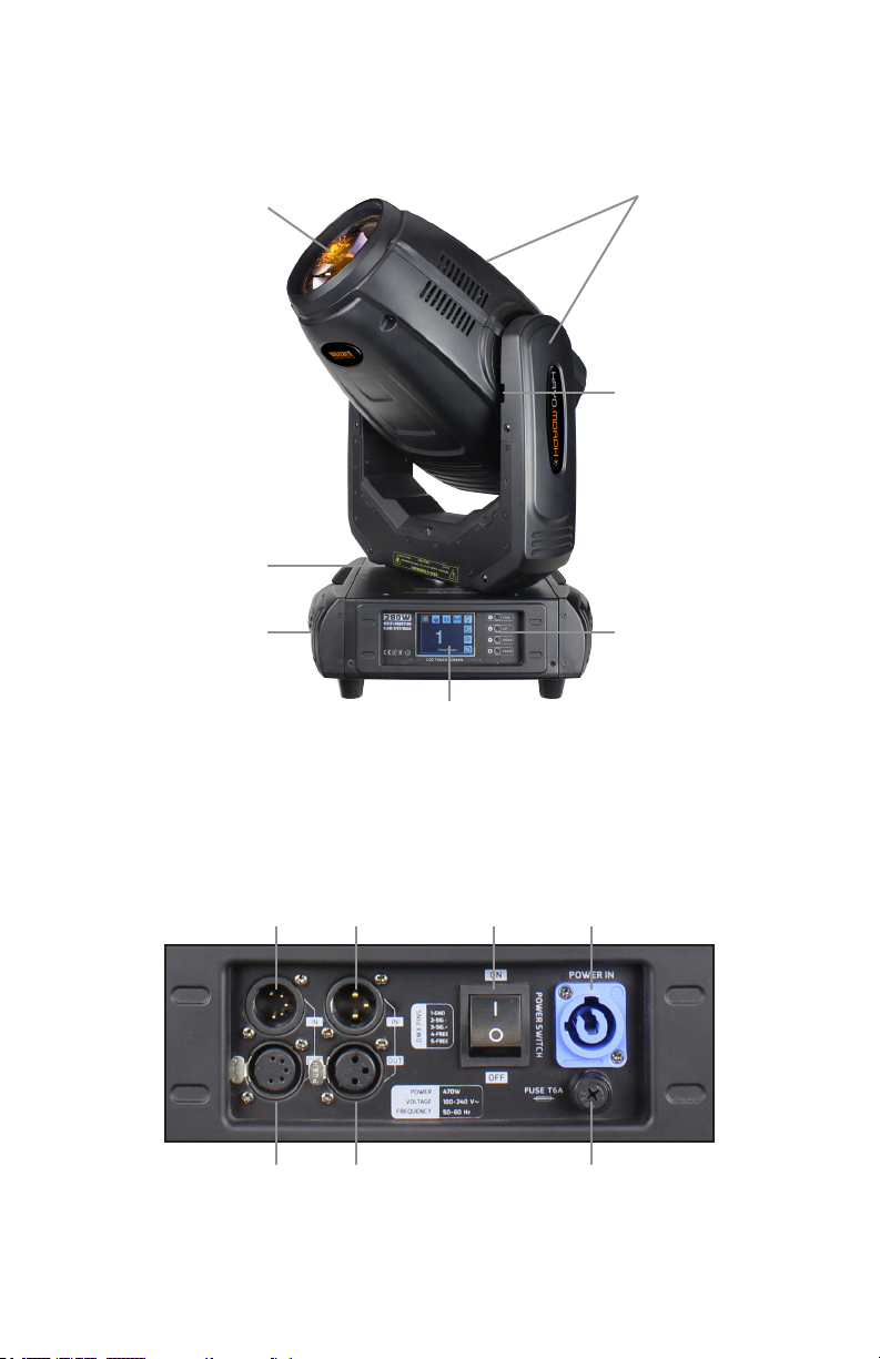
Figure 1: The Kryo.Morph™ Pin-Up Picture
HRI 280W
Discharge
Lamp
*The pan and tilt
lock latches should
be in their locked
positions during
transportation.
Move these
latches to their
unlocked positions
before operating
the xture.
Pan
Lock
Carry
Handle
Touchscreen LCD Display
Figure 2: The Rear Connections
Head/Arms
Tilt
Lock
Control
Buttons
In
3-Pin
DMX
In
3-Pin
DMX
Out
Page 6
Power
Switch
Power
Input
Fuse Holder
5-Pin
DMX
5-Pin
DMX
Out
Kryo.Morph™ User Manual - Rev. A (c) 2016 Blizzard Lighting, LLC
Page 7

3. SETUP
Fuse Replacement
With a phillips head screwdriver, unscrew the fuse holder out of its
housing. Remove the damaged fuse from its holder and replace with
exact same type of fuse. Reattach the fuse holder, and then reconnect
power.
Connecting A Bunch of Kryo.Morph™ Fixtures
You will need a serial data link to run light shows using a DMX-512
controller or to run shows on two or more xtures set to sync in master/slave operating mode. The combined number of channels required
by all the xtures on a serial data link determines the number of xtures the data link can support.
Fixtures on a serial data link must be daisy chained in one single line.
Also, connecting more than 32 xtures on one serial data link without
the use of a DMX optically-isolated splitter may result in deterioration
of the digital DMX signal. The maximum recommended cable-run distance is 500 meters (1640 ft). The maximum recommended number of
xtures on a serial data link is 32 xtures.
Data/DMX Cabling
To link xtures together you’ll need data cables. You should use data-
grade cables that can carry a high quality signal and are less prone to
electromagnetic interference.
For instance, Belden© 9841 meets the specications for EIA RS-485
applications. Standard microphone cables will “probably” be OK, but
note that they cannot transmit DMX data as reliably over long distances. In any event, the cable should have the following characteristics:
2-conductor twisted pair plus a shield
Maximum capacitance between conductors – 30 pF/ft.
Maximum capacitance between conductor & shield – 55 pF/ft.
Maximum resistance of 20 ohms / 1000 ft.
Nominal impedance 100 – 140 ohms
Kryo.Morph™ User Manual - Rev. A (c) 2016 Blizzard Lighting, LLC
Page 7
Page 8
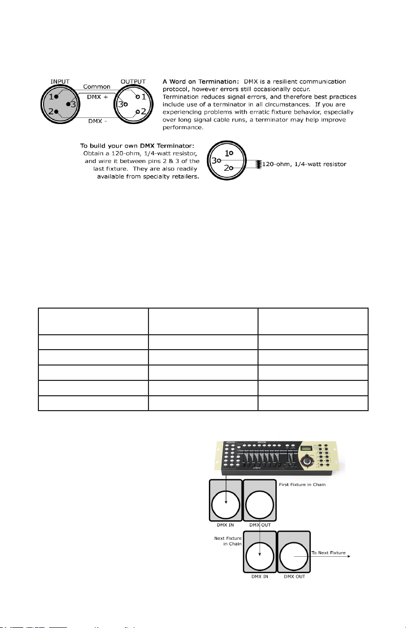
Cable Connectors
Cables must have a male XLR connector on one end and a female XLR
connector on the other end. (Duh!)
CAUTION: Do not allow contact between the common and the x-
ture’s chassis ground. Grounding the common can cause a ground
loop, and your xture may perform erratically. Test cables with an
ohm meter to verify correct polarity and to make sure the pins are not
grounded or shorted to the shield or each other.
3-Pin??? 5-Pin??? Huh?!?
If you use a controller with a 5 pin DMX output connector, you will need to use a 5 pin to 3-pin adapter.
They are widely available over the internet and from specialty retailers If you’d like to build your own, the
chart below details a proper cable conversion:
Conductor 3-Pin Female
(Output)
5-Pin Male
(Input)
Ground/Shield Pin 1 Pin 1
DMX Data (-) Pin 2 Pin 2
DMX Data (+) Pin 3 Pin 3
Not Used. No Connection. No Connection.
Not Used. No Connection. No Connection.
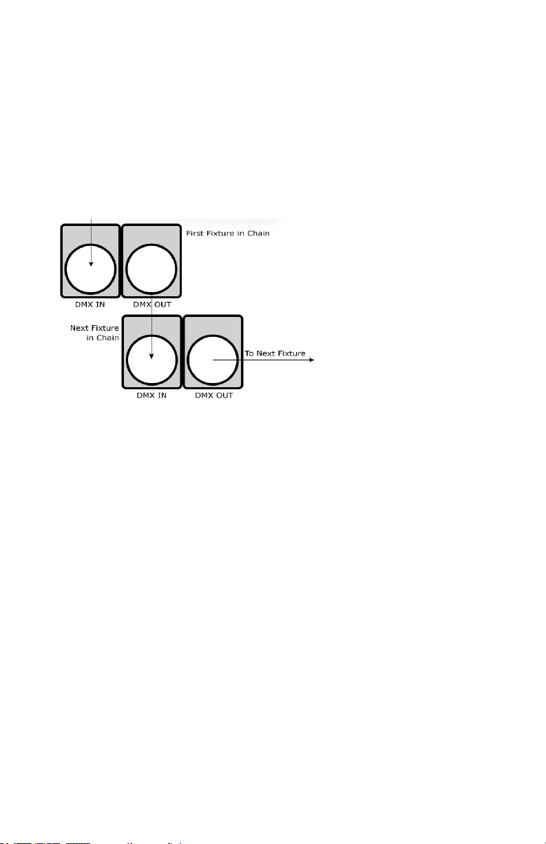
Take It To The Next Level: Setting Up DMX Control
Step 1: Connect the male connector of the
DMX cable to the female connector (output)
on the controller.
Step 2: Connect the female connector of the
DMX cable to the rst xture’s male connector (input). Note: It doesn’t matter which
xture address is the rst one connected.
We recommend connecting the xtures in
terms of their proximity to the controller,
rather than connecting the lowest xture
number rst, and so on.
Step 3: Connect other xtures in the chain
from output to input as above. Place a DMX
terminator on the output of the nal xture
to ensure best communication.
Kryo.Morph™ User Manual - Rev. A (c) 2016 Blizzard Lighting, LLC
Page 8
Page 9
Fixture Linking (Master/Slave Mode)
1. Connect the (male) 3/5-pin connector side of the
DMX cable to the output (female) 3/5-pin connector
of the rst xture.
2. Connect the end of the cable coming from the
rst xture which will have a (female) 3/5-pin connector to the input connector of the next xture
consisting of a (male) 3/5-pin connector. Then, proceed to connect from the output as stated above to
the input of the following xture and so on.
A quick note: Often,
the setup for MasterSlave and Standalone
operation requires that
the rst xture in the
chain be initialized for
this purpose via either
settings in the control
panel or DIP-switches.
Secondarily, the xtures
that follow may also require a slave setting.
Check the “Operating Adjustments” section in this manual for com-
plete instructions for this type of setup and conguration.
Mounting & Rigging
This xture may be mounted in any SAFE position provided there is
enough room for ventilation.
It is important never to obstruct the fan or vents pathway. Mount the
xture using a suitable “C” or “O” type clamp. The clamp should be
rated to hold at least 10x the xture’s weight to ensure structural sta-
bility. Do not mount to surfaces with unknown strength, and ensure
properly “rated” rigging is used when mounting xtures overhead.
Adjust the angle of the xture by loosening both knobs and tilting the
xture. After nding the desired position, retighten both knobs.
• When selecting installation location, take into consideration lamp
replacement access (if applicable) and routine maintenance.
• Safety cables MUST ALWAYS be used.
• Never mount in places where the xture will be exposed to rain,
high humidity, extreme temperature changes or restricted ventilation.
Kryo.Morph™ User Manual - Rev. A (c) 2016 Blizzard Lighting, LLC
Page 9
Page 10

Mounting Points
Overhead mounting requires extensive experience, which includes
calculating working load limits, knowledge of the installation material
being used, and periodic safety inspection of all installation material
and the xture. If you lack these qualications, do not attempt the
installation yourself. Improper installation can result in bodily injury.
Caution!
Please be aware, you should have a qualied electrician performing all
of your electrical connection needs. Better safe than sorry!
Be sure to complete all rigging and installation procedures before
connecting the main power cord to the appropriate wall outlet.
Kryo.Morph™ User Manual - Rev. A (c) 2016 Blizzard Lighting, LLC
Page 10
Page 11

Clamp Mounting
This xture provides a mounting bracket assembly that secures the
bottom of the base, the “Omega Brackets,” and the safety cable
rigging point together. When mounting this xture to truss, be sure to
secure an appropriately rated clamp to the omega bracket using an
M10 screw tted through the center hole of the “omega bracket”.
1.) Clamp
1
2.) Omega Bracket
3.) ¼ Turn Quick Lock Fasteners
2
3
Securing the Fixture
Regardless of the rigging option you choose for your xtures always be
sure to secure your xture with a safety cable. Be sure to only use the
designated rigging point found on the underside of the base assembly
for the safety cable. Never secure a safety cable to a carrying handle.
Kryo.Morph™ User Manual - Rev. A (c) 2016 Blizzard Lighting, LLC
Page 11
Page 12

Changing The Lamp
DANGER: Install the lamp with the xture unplug from mains!
WARNING: Do not touch the lamp’s envelope with bare hands. Should this
happen, clean the bulb with a cloth soaked in alcohol and dry it.
1.) First disconnect the xture from mains and allow it to cool for at least 20
minutes.
Phillips
Head
Screw
Phillips
Head
Screw
Lamp Compartment Cover
(rear side of the head)
Phillips
Head
Screw
Phillips
Head
Screw
2.) Remove the lamp compartment cover from the rear side of the head by taking out the 4 phillips head screws that hold it in place.
3.) Remove both electrical fastons from the at blades of the lamp.
4.) Holding the lamp by its ceramic base, carefully pull it outwards until it snaps
free from the spring locks that hold it in place, and remove the old lamp from
the compartment.
5.) Holding the new lamp by its ceramics base, insert it into the lamp compartment until it snaps into place (held by the spring locks).
Note: Do not install a lamp with a higher wattage!
A lamp like this will generate temperatures this xture is not designed for.
Damages caused by non-observance are not subject to warranty.
6.) Slide both fastons onto the new lamp blades
7.) Reinstall the lamp compartment cover.
Never operate this xture without the lamp!
Do not operate this xture without the lamp cover!
Kryo.Morph™ User Manual - Rev. A (c) 2016 Blizzard Lighting, LLC
Page 12
Page 13

Lamp Adjustment
The lamp holder is aligned at the factory. Due to differences between lamps,
ne adjustment may improve light performance. This
xture is designed to make horizontal (left and right)
ne adjustments.
1.) Connect the xture to the mains, switch on the
lamp, open shutter and dimmer, set zoom and focus
(static gobo wheel and rotating gobo wheel should be
set at zero), and check the image on the wall.
Image on the wall
2.) The hot spot should be fairly centered within the
circle of light that is projected on the wall.
Centered lamp
3.) If needed, the lamp needs to move into the direction of shifted hot spot.
Move the lamp
to the right
Loosen
Hex
Screw
Edge of
Lamp
Holder
Loosen
Hex
Screw
Lamp Compartment:
Move the lamp
to the left
Loosen
Hex
Screw
Edge of
Lamp
Holder
Loosen
Hex
Screw
4.) Disconnect the xture from mains, and remove the lamp compartment
cover (see page 12).
5.) Loosen (but do not remove) the 4 hex screws that secure the lamp holder.
6.) Place a at head screwdriver on the left or right edge of the lamp holder,
and gently push the horizontally sliding lamp holder to the left or right to make
any ne adjustments, then re-tighten the hex screws.
7.) Reinstall the lamp compartment cover, connect the xture to the mains and
check if the adjustment has been correctly made. To adjust again, disconnect
the xture from mains and repeat.
Kryo.Morph™ User Manual - Rev. A (c) 2016 Blizzard Lighting, LLC
Page 13
Page 14

4. OPERATING ADJUSTMENTS
The Control Panel
All the goodies and different modes possible with the Kryo.Morph™ are ac-
cessed by using the control panel on the front of the xture. In addition to the
on-screen touch sensitive menu icons, there are 4 control menu buttons to the
right of the LCD display which allow you to navigate through the various control
panel menus.
<FUNC>
Is used to return to the main menu navigation screen.
<UP>
Scrolls through menu items and numbers in ascending order.
<DOWN>
Scrolls through menu items and numbers in descending order.
<ENTER>
Is used to select and conrm/store the current selection.
The control panel LCD display shows the menu items you select from the menu
map on pages 15-16. On the home screen there are 8 icons to choose from,
Feature Settings, Manual, System Info, Display Settings, Lamp Settings, Rotate Display, Language, and Back to Home icons.
The 4 corresponding buttons are <FUNC>, <UP>, <DOWN>, and <ENTER>.
Press the <ENTER> button once from startup to reach the home screen, use
the <UP/DOWN> buttons to scroll through the menu, press <ENTER> for the
sub menu to make changes or touch the icon on the screen.
Kryo.Morph™ User Manual - Rev. A (c) 2016 Blizzard Lighting, LLC
Page 14
Page 15

Control Panel Menu Structure
Icon Level 1 Level 2 Level 3
FEATURES SETTING Run Mode DMX / Wire (slave) / Auto
ChanMode DEFE (13-channel mode)
SMAL (16-channel mode)
STAN (20-channel mode)
X Reverse ON/OFF
Y Reverse ON/OFF
X. Angle 540
XY Fback ON/OFF
SignalClear ON/OFF
Full Color ON/OFF
Shortcut ON/OFF
RST.
SAVE
ESC
ADV. Zero. Set
Chan. Def.
Fact. Set
Use. Mang.
ESC
UNLOCK PassWord1 (0-255)
PassWord2 (0-255)
KEY
ESC
Passwords:
Zero. Set/Chan. Def. 1,0
Fact. Set 1,2
Use. Mang. 3,4
MANUAL REST (reset) ALL MOTOR (Yes/No)
PART MOTOR (Yes/No)
XY MOTOR (Yes/No)
TEST RUN AUTO
SOUND
ESC
SMULATE DMX (Add value
to the DMX channels)
CH1-CH32 (0-255)
ESC
Kryo.Morph™ User Manual - Rev. A (c) 2016 Blizzard Lighting, LLC
Page 15
Page 16

Control Panel Menu Structure (continued)
Icon Level 1 Level 2 Level 3
SYSTEM INFO DMX VALUE CH1-CH32(0-255)
ESC
OTHER INFO Run Time (0-9999)
Run Count (0-9999)
Fan 1 (0-9999)
Fan 2 (0-9999)
Temp 1 (0-100)
Temp 2 (0-100)
ESC
ERROR INFO Color
RotGobos
FixeGobo
Plane
Tilt
RotGobos1
Prism
Effect
Prism.R
Effect.R
Zoom
Focus
ESC
DISPLAY SETTINGS Brightness Level 1-7
LightDelay 10Sec/20Sec/30Sec/On
Menuback 10Sec/20Sec/30Sec/Off
Flicker ON/OFF
Save
ESC
LAMP SETTINGS Default ON/OFF
Manual ON/OFF
Electronic ON/OFF
ESC
ROTATE DISPLAY Change orientation of
LANGUAGE Chinese/English
the display
BACK Back to LOGO screen
Kryo.Morph™ User Manual - Rev. A (c) 2016 Blizzard Lighting, LLC
Page 16
Page 17

DMX Values In-Depth (16/24-Channel Mode)
Standard
Mode: 24ch
1 1 000 <--> 255 Pan
2 -- 000 <--> 255 Fine Pan
3 2 000 <--> 255 Tilt
4 -- 000 <--> 255 Fine Tilt
5 3 000 <--> 255 Pan/Tilt Speed
6 4
7 5
8 -- -- Reserved
9 6 -- Reserved
Compact
Mode: 16ch
Value What It Does
000 <--> 049
050 <--> 059
060 <--> 069
070 <--> 079
080 <--> 089
090 <--> 099
100 <--> 109
110 <--> 119
120 <--> 129
130 <--> 139
140 <--> 149
150 <--> 189
190 <--> 199
200 <--> 209
210 <--> 229
230 <--> 239
240 <--> 255
0
9
18
27
37
46
55
64
73
82
91
101
110
119
128 <--> 129
130 <--> 134
135 <--> 138
139 <--> 143
144 <--> 147
148 <--> 152
153 <--> 157
158 <--> 161
162 <--> 166
167 <--> 171
172 <--> 176
177 <--> 180
181 <--> 185
186 <--> 189
190 <--> 215
216 <--> 217
218 <--> 243
244 <--> 249
250 <--> 255
Macro Function
Blank
Pan/Tilt Speed Mode
Pan/Tilt Time Mode
Blackout while pan/tilt moves
Disabled blackout while pan/tilt moves
Blackout while color wheel moves
Disabled blackout while color wheel moves
Blackout while gobo wheel moving
Disabled blackout while gobo wheel moves
Lamp On, reset all (except pan/tilt)
Pan/Tilt Reset
Effects Reset
Blank
Light Reset
Blank
Lamp Off By Controller
Blank
Color Wheel (continual positioning)
White
Deep Red
Deep Blue
Yellow
Green
Magenta
Azure
Red
Deep Green
Amber
Blue
Orange
Cooling
Fluorescent Blue
White
Color Wheel (positioning by color)
Crimson
Deep Blue
Yellow
Green
Magenta
Azure
Red
Deep Green
Amber
Blue
Orange
Cooling
Fluorescent Blue
Forwards rainbow effect (fast <--> slow)
No Rotation
Backwards rainbow effect (slow <--> fast)
Random color selection by sound control
Random color selection by audio control
Kryo.Morph™ User Manual - Rev. A (c) 2016 Blizzard Lighting, LLC
Page 17
Page 18

DMX Values In-Depth (16/24-Channel Mode), continued
Standard
Mode: 24ch
10 7
11 8
Compact
Mode: 16ch
Value What It Does
000 <--> 003
004 <--> 009
010 <--> 015
016 <--> 021
022 <--> 027
028 <--> 033
034 <--> 039
040 <--> 045
046 <--> 051
052 <--> 057
058 <--> 063
064 <--> 069
070 <--> 075
076 <--> 087
088 <--> 095
096 <--> 103
104 <--> 111
112 <--> 119
120 <--> 127
128 <--> 135
136 <--> 143
144 <--> 151
152 <--> 159
160 <--> 167
168 <--> 175
176 <--> 183
184 <--> 199
200 <--> 201
202 <--> 221
222 <--> 223
224 <--> 243
244 <--> 249
250 <--> 255
000 <--> 004
005 <--> 007
008 <--> 010
011 <--> 013
014 <--> 016
017 <--> 019
020 <--> 022
023 <--> 025
026 <--> 028
029 <--> 031
032 <--> 034
035 <--> 037
038 <--> 040
041 <--> 043
044 <--> 046
047 <--> 049
050 <--> 052
053 <--> 055
056 <--> 059
060 <--> 067
068 <--> 075
076 <--> 083
084 <--> 091
092 <--> 099
100 <--> 107
108 <--> 115
116 <--> 123
124 <--> 129
Static Gobo Wheel
Open
Gobo 1
Gobo 2
Gobo 3
Gobo 4
Gobo 5
Gobo 6
Gobo 7
Gobo 8
Gobo 9
Gobo 10
Beam reducer 1
Beam reducer 2
Beam reducer 3
Gobo 1 Shake (slow <--> fast)
Gobo 2 Shake (slow <--> fast)
Gobo 3 Shake (slow <--> fast)
Gobo 4 Shake (slow <--> fast)
Gobo 5 Shake (slow <--> fast)
Gobo 6 Shake (slow <--> fast)
Gobo 7 Shake (slow <--> fast)
Gobo 8 Shake (slow <--> fast)
Gobo 9 Shake (slow <--> fast)
Gobo 10 Shake (slow <--> fast)
Beam reducer 1
Beam reducer 2
Beam reducer 3
Open
Forwards gobo wheel rotation (fast <--> slow)
No rotation
Backwards gobo wheel rotation (slow <--> fast)
Random gobo selection by audio control
Auto random gobo (fast <--> slow)
Rotating Gobo Wheel
Blank
Gobo 1
Gobo 2
Gobo 3
Gobo 4
Gobo 5
Gobo 6
Gobo 7
Gobo 8
Gobo 9
Gobo 1
Gobo 2
Gobo 3
Gobo 4
Gobo 5
Gobo 6
Gobo 7
Gobo 8
Gobo 9
Gobo 1 Shake
Gobo 2 Shake
Gobo 3 Shake
Gobo 4 Shake
Gobo 5 Shake
Gobo 6 Shake
Gobo 7 Shake
Gobo 8 Shake
Gobo 9 Shake
*Set indexing
on channel 12/9
*Set rotation on
channel 12/9
*Set indexing on
channel 12/9
(slow <--> fast)
Kryo.Morph™ User Manual - Rev. A (c) 2016 Blizzard Lighting, LLC
Page 18
Page 19

DMX Values In-Depth (16/24-Channel Mode), continued
Standard
Mode: 24ch
11 8
12 9
13 -- -- Reserved
14 10
15 11
16 12 000 <--> 064
17 13
18 --
19 14
20 --
Compact
Mode: 16ch
Value What It Does
130 <--> 137
138 <--> 145
146 <--> 153
154 <--> 161
162 <--> 169
170 <--> 177
178 <--> 185
186 <--> 193
194 <--> 199
200 <--> 201
202 <--> 221
222 <--> 223
224 <--> 243
244 <--> 249
250 <--> 255
000 <--> 127
128 <--> 177
178 <--> 203
204 <--> 255
000 <--> 019
020 <--> 049
050 <--> 075
076 <--> 105
106 <--> 127
128 <--> 135
136 <--> 143
144 <--> 151
152 <--> 159
160 <--> 167
168 <--> 175
176 <--> 183
184 <--> 191
192 <--> 199
200 <--> 207
208 <--> 215
216 <--> 223
224 <--> 231
232 <--> 239
240 <--> 247
248 <--> 255
000 <--> 127
128 <--> 191
192 <--> 193
194 <--> 255
065 <--> 255
000 <--> 255
000 <--> 255
000 <--> 255
000 <--> 255
Static Gobo Wheel (continued)
Gobo 1 Shake
Gobo 2 Shake
Gobo 3 Shake
Gobo 4 Shake
Gobo 5 Shake
Gobo 6 Shake
Gobo 7 Shake
Gobo 8 Shake
Gobo 9 Shake
Open
Forwards gobo wheel rotation (fast <--> slow)
No rotation
Backwards gobo wheel rotation (slow <--> fast)
Random gobo selection by audio control
Auto random gobo (fast <--> slow)
Gobo Rotation
Indexing
Backwards gobo rotation (slow <--> fast)
Stop
Forwards gobo rotation (fast <--> slow)
Prism
Open
6-facet linear rotating prism
6-facet circular rotating prism
8-facet linear rotating prism
8-facet circular rotating prism
Macro function 1
Macro function 2
Macro function 3
Macro function 4
Macro function 5
Macro function 6
Macro function 7
Macro function 8
Macro function 9
Macro function 10
Macro function 11
Macro function 12
Macro function 13
Macro function 14
Macro function 15
Macro function 16
Prism Rotation
Index
Forward prism rotation (fast <--> slow)
No rotation
Backward prism rotation (slow <--> fast)
Frost
Open
Frost (0% <--> 100%)
Zoom
From maximum to minimum beam angle
Zoom - Fine
Fine zooming
Focus
Continuous adjustment (far <--> near)
Focus - Fine
Fine focusing
*Set rotation on
channel 12/9
(slow <--> fast)
Kryo.Morph™ User Manual - Rev. A (c) 2016 Blizzard Lighting, LLC
Page 19
Page 20

DMX Values In-Depth (16/24-Channel Mode), continued
Standard 24ch Small 16ch Value What It Does
21 -- -- Reserved
000 <--> 031
032 <--> 063
064 <--> 095
22 15
23 16
24 -- -- Reserved
096 <--> 127
128 <--> 143
144 <--> 159
160 <--> 191
192 <--> 223
224 <--> 255
000 <--> 255
Shutter/Strobe
Shutter closed
Shutter open
Strobe effect (slow <--> fast)
Strobe open
Closing pulse in sequences (fast <--> slow)
Opening pulse in sequences (slow <--> fast)
Shutter open
Random strobe effect (slow <--> fast)
Shutter open
Dimmer
Dimmer intensity (0% <--> 100%)
DMX Values In-Depth (13-Channel Mode)
Defe 13-ch Value What It Does
0
9
18
27
37
46
55
64
73
82
91
101
110
119
128 <--> 129
1
2
130 <--> 134
135 <--> 138
139 <--> 143
144 <--> 147
148 <--> 152
153 <--> 157
158 <--> 161
162 <--> 166
167 <--> 171
172 <--> 176
177 <--> 180
181 <--> 185
186 <--> 189
190 <--> 215
216 <--> 217
218 <--> 243
244 <--> 249
250 <--> 255
000 <--> 031
032 <--> 063
064 <--> 095
096 <--> 127
Color Wheel (continual positioning)
White
Deep Red
Deep Blue
Yellow
Green
Magenta
Azure
Red
Deep Green
Amber
Blue
Orange
Cooling
Fluorescent Blue
White
Color Wheel (positioning by color)
Crimson
Deep Blue
Yellow
Green
Magenta
Azure
Red
Deep Green
Amber
Blue
Orange
Cooling
Fluorescent Blue
Forwards rainbow effect (fast <--> slow)
No Rotation
Backwards rainbow effect (slow <--> fast)
Random color selection by sound control
Random color selection by audio control
Shutter/Strobe
Shutter closed
Shutter open
Strobe effect (slow <--> fast)
Strobe open
Kryo.Morph™ User Manual - Rev. A (c) 2016 Blizzard Lighting, LLC
Page 20
Page 21

DMX Values In-Depth (13-Channel Mode), continued
Defe 13-ch Value What It Does
128 <--> 143
2
3
4
5
144 <--> 159
160 <--> 191
192 <--> 223
224 <--> 255
000 <--> 255
000 <--> 003
004 <--> 009
010 <--> 015
016 <--> 021
022 <--> 027
028 <--> 033
034 <--> 039
040 <--> 045
046 <--> 051
052 <--> 057
058 <--> 063
064 <--> 069
070 <--> 075
076 <--> 087
088 <--> 095
096 <--> 103
104 <--> 111
112 <--> 119
120 <--> 127
128 <--> 135
136 <--> 143
144 <--> 151
152 <--> 159
160 <--> 167
168 <--> 175
176 <--> 183
184 <--> 199
200 <--> 201
202 <--> 221
222 <--> 223
224 <--> 243
244 <--> 249
250 <--> 255
000 <--> 019
020 <--> 049
050 <--> 075
076 <--> 105
106 <--> 127
128 <--> 135
136 <--> 143
144 <--> 151
152 <--> 159
160 <--> 167
168 <--> 175
176 <--> 183
184 <--> 191
192 <--> 199
200 <--> 207
208 <--> 215
216 <--> 223
224 <--> 231
232 <--> 239
240 <--> 247
248 <--> 255
Closing pulse in sequences (fast <--> slow)
Opening pulse in sequences (slow <--> fast)
Shutter open
Random strobe effect (slow <--> fast)
Shutter open
Dimmer
Dimmer intensity (0% <--> 100%)
Static Gobo Wheel
Open
Gobo 1
Gobo 2
Gobo 3
Gobo 4
Gobo 5
Gobo 6
Gobo 7
Gobo 8
Gobo 9
Gobo 10
Beam reducer 1
Beam reducer 2
Beam reducer 3
Gobo 1 Shake (slow <--> fast)
Gobo 2 Shake (slow <--> fast)
Gobo 3 Shake (slow <--> fast)
Gobo 4 Shake (slow <--> fast)
Gobo 5 Shake (slow <--> fast)
Gobo 6 Shake (slow <--> fast)
Gobo 7 Shake (slow <--> fast)
Gobo 8 Shake (slow <--> fast)
Gobo 9 Shake (slow <--> fast)
Gobo 10 Shake (slow <--> fast)
Beam reducer 1
Beam reducer 2
Beam reducer 3
Open
Forwards gobo wheel rotation (fast <--> slow)
No rotation
Backwards gobo wheel rotation (slow <--> fast)
Random gobo selection by audio control
Auto random gobo (fast <--> slow)
Prism
Open
6-facet linear rotating prism
6-facet circular rotating prism
8-facet linear rotating prism
8-facet circular rotating prism
Macro function 1
Macro function 2
Macro function 3
Macro function 4
Macro function 5
Macro function 6
Macro function 7
Macro function 8
Macro function 9
Macro function 10
Macro function 11
Macro function 12
Macro function 13
Macro function 14
Macro function 15
Macro function 16
Kryo.Morph™ User Manual - Rev. A (c) 2016 Blizzard Lighting, LLC
Page 21
Page 22

DMX Values In-Depth (13-Channel Mode), continued
Defe 13-ch Value What It Does
6
7
8 000 <--> 064
9
10 000 <--> 255 Pa n
11 000 <--> 255 Fine Pan
12 000 <--> 255 Tilt
13 000 <--> 255 Fine Tilt
000 <--> 127
128 <--> 191
192 <--> 193
194 <--> 255
000 <--> 004
005 <--> 007
008 <--> 010
011 <--> 013
014 <--> 016
017 <--> 019
020 <--> 022
023 <--> 025
026 <--> 028
029 <--> 031
032 <--> 034
035 <--> 037
038 <--> 040
041 <--> 043
044 <--> 046
047 <--> 049
050 <--> 052
053 <--> 055
056 <--> 059
060 <--> 067
068 <--> 075
076 <--> 083
084 <--> 091
092 <--> 099
100 <--> 107
108 <--> 115
116 <--> 123
124 <--> 129
065 <--> 255
000 <--> 255
Prism Rotation
Index
Forward prism rotation (fast <--> slow)
No rotation
Backward prism rotation (slow <--> fast)
Rotating Gobo Wheel
Blank
Gobo 1
Gobo 2
Gobo 3
Gobo 4
Gobo 5
Gobo 6
Gobo 7
Gobo 8
Gobo 9
Gobo 1
Gobo 2
Gobo 3
Gobo 4
Gobo 5
Gobo 6
Gobo 7
Gobo 8
Gobo 9
Gobo 1 Shake
Gobo 2 Shake
Gobo 3 Shake
Gobo 4 Shake
Gobo 5 Shake
Gobo 6 Shake
Gobo 7 Shake
Gobo 8 Shake
Gobo 9 Shake
Frost
Open
Frost (0% <--> 100%)
Focus
Continuous adjustment (far <--> near)
Kryo.Morph™ User Manual - Rev. A (c) 2016 Blizzard Lighting, LLC
Page 22
Page 23

Gobo Replacement
1) Remove the gobo cover by removing the four screws on the top of the xture head.
2) Remove the slot-n-lock gobo from the gobo wheel by lifting up slightly and sliding it out.
3) Using a small tool, pry the tension ring from the gobo holder.
4) Remove the old gobo, insert the new gobo, and replace in the reverse steps of removal.
Troubleshooting
Symptom Solution
Fixture Auto-Shut
Off
Beam is Dim Check optical system and clean excess dust/grime. Also ensure that
No Light Output Check to ensure xture is operating under correct mode, IE sound
No Power Check fuse, AC cord and circuit for malfunction.
Blown Fuse Check AC cord and circuit for damage, verify that moving parts are
Slow Movement Check that speed channels are set appropriately.
No Response to
Audio
Fixture Not
Responding /
Responding Erratically
Fixture Moving
On Its Own
Check the fan in the xture. If it is stopped or moving slower than
normal, the unit may have shut itself off due to high heat. This is to
protect the xture from overheating. Clear the fan of obstructions,
or return the unit for service.
the 220V/110V switch is in the correct position, if applicable.
active/auto/DMX/Etc., if applicable.
not restricted and that unit’s ventilation is not obstructed
Verify that the xture is in “Sound Active” mode.
Adjust Audio Sensitivity, If Applicable.
Make sure all connectors are seated properly and securely.
Use Only DMX Cables.
Install a Terminator.
Check all cables for defects.
Reset xture(s).
Verify proper mode of operation. Is the xture in “Auto” mode?
please open a support ticket at www.blizzardlighting.com/support.
If your problem isn’t listed, or if problems persist,
Kryo.Morph™ User Manual - Rev. A (c) 2016 Blizzard Lighting, LLC
Page 23
Page 24

5. APPENDIX
A Quick Lesson On DMX
DMX (aka DMX-512) was created in 1986 by the United States Institute for Theatre
Technology (USITT) as a standardized method for connecting lighting consoles to lighting
dimmer modules. It was revised in 1990 and again in 2000 to allow more exibility. The
Entertainment Services and Technology Association (ESTA) has since assumed control over
the DMX512 standard. It has also been approved and recognized for ANSI standard clas-
sication.
DMX covers (and is an abbreviation for) Digital MultipleXed signals. It is the most common
communications standard used by lighting and related stage equipment.
DMX provides up to 512 control “channels” per data link. Each of these channels was originally intended to control lamp dimmer levels. You can think of it as 512 faders on a lighting
console, connected to 512 light bulbs. Each slider’s position is sent over the data link as an
8-bit number having a value between 0 and 255. The value 0 corresponds to the light bulb
being completely off while 255 corresponds to the light bulb being fully on.
DMX data is transmitted at 250,000 bits per second using the RS-485 transmission standard over two wires. As with microphone cables, a grounded cable shield is used to prevent
interference with other signals.
There are ve pins on a DMX connector: a wire for ground (cable shield), two wires for
“Primary” communication which goes from a DMX source to a DMX receiver, and two wires
for a “Secondary” communication which goes from a DMX receiver back to a DMX source.
Generally, the “Secondary” channel is not used so data ows only from sources to receivers. Hence, most of us are most familiar with DMX-512 as being employer over typical
3-pin “mic cables,” although this does not conform to the dened standard.
DMX is connected using a daisy-chain conguration where the source connects to the input
of the rst device, the output of the rst device connects to the input of the next device,
and so on. The standard allows for up to 32 devices on a single DMX link.
Each receiving device typically has a means for setting the “starting channel number” that
it will respond to. For example, if two 6-channel xtures are used, the rst xture might
be set to start at channel 1 so it would respond to DMX channels 1 through 6, and the next
xture would be set to start at channel 7 so it would respond to channels 7 through 12.
The greatest strength of the DMX communications protocol is that it is very simple and
robust. It involves transmitting a reset condition (indicating the start of a new “packet”),
a start code, and up to 512 bytes of data. Data packets are transmitted continuously. As
soon as one packet is nished, another can begin with no delay if desired (usually another
follows within 1 ms). If nothing is changing (i.e. no lamp levels change) the same data will
be sent out over and over again. This is a great feature of DMX -- if for some reason the
data is not interpreted the rst time around, it will be re-sent shortly.
Not all 512 channels need to be output per packet, and in fact, it is very uncommon to nd
all 512 used. The fewer channels are used, the higher the “refresh” rate. It is possible to
get DMX refreshes at around 1000 times per second if only 24 channels are being transmitted. If all 512 channels are being transmitted, the refresh rate is around 44 times per
second.
In summary, since its design and evolution in the 1980’s DMX has become the standard
for lighting control. It is exible, robust, and scalable, and its ability to control everything
from dimmer packs to moving lights to foggers to lasers makes it an indispensable tool for
any lighting designer or lighting performer.
Kryo.Morph™ User Manual - Rev. A (c) 2016 Blizzard Lighting, LLC
Page 24
Page 25

Keeping Your Kryo.Morph™ As Good As New
The xture you’ve received is a rugged, tough piece of pro lighting equipment, and as long as you take care of it, it will take care of you. That said, like
anything, you’ll need to take care of it if you want it to operate as designed.
You should absolutely keep the xture clean, especially if you are using it in an
environment with a lot of dust, fog, haze, wild animals, wild teenagers or spilled
drinks.
Cleaning the optics routinely with a suitable glass cleaner will greatly improve
the quality of light output. Keeping the fans free of dust and debris will keep
the xture running cool and prevent damage from overheating.
In transit, keep the xtures in cases. You wouldn’t throw a prized guitar,
drumset, or other piece of expensive gear into a gear trailer without a case,
and similarly, you shouldn’t even think about doing it with your shiny new light
xtures.
Common sense and taking care of your xtures will be the single biggest thing
you can do to keep them running at peak performance and let you worry about
designing a great light show, putting on a great concert, or maximizing your client’s satisfaction and “wow factor.” That’s what it’s all about, after all!
Returns (Gasp!)
We’ve taken a lot of precautions to make sure you never even have to worry
about sending a defective unit back, or sending a unit in for service. But, like
any complex piece of equipment designed and built by humans, once in a while,
something doesn’t go as planned. If you nd yourself with a xture that isn’t
behaving like a good little xture should, you’ll need to obtain a Return Authori-
zation (RA).
Don’t worry, this is easy. Just go to our website and open a support ticket at
www.blizzardlighting.com/support, and we’ll issue you an RA. Then, you’ll need
to send the unit to us using a trackable, pre-paid freight method. We suggest
using USPS Priority or UPS. Make sure you carefully pack the xture for transit,
and whenever possible, use the original box & packing for shipping.
When returning your xture for service, be sure to include the following:
1.) Your contact information (Name, Address, Phone Number, Email address).
2.) The RA# issued to you
3.) A brief description of the problem/symptoms.
We will, at our discretion, repair or replace the xture. Please remember that
any shipping damage which occurs in transit to us is the customer’s responsibility, so pack it well!
Shipping Issues
Damage incurred in shipping is the responsibility of the shipper, and
must be reported to the carrier immediately upon receipt of the items.
Claims must be made within seven (7) days of receipt.
Kryo.Morph™ User Manual - Rev. A (c) 2016 Blizzard Lighting, LLC
Page 25
Page 26

Tech Specs!
Weight & Dimensions
Width 15.3 inches (388 mm)
Depth 10.6 inches (269 mm)
Height 23.4 inches (594 mm)
Weight 15.5 lbs (34.2 kg)
Power
Operating Voltage 100-240VAC, 50-60 Hz (autoranging)
Fuse 5A 250V
Power Consumption 365W, 3.12A, PF: .99
Light Source
Lamp HRI 280W discharge lamp
Optical
Beam Angle 2.5°-10° beam application, 5°–20° spot application
Beam mode narrow: 132,811 lux @ 5M
Beam mode wide: 46,094 lux @ 5M
Spot mode narrow: 76,955 lux @ 5M
Spot mode wide: 6,588 lux @ 5M
Luminous Intensity
Gobo Size 14.75mm (external dimensions), 13mm (inner dimensions)
Movement Range
Pan 540°
Tilt 270°
Wash mode narrow: 12,420 lux @ 5M
Wash mode wide: 3,707 lux @ 5M
Thermal
Max. Operating Temp. 104 degrees F (40 degrees C) ambient
Control
Protocol USITT DMX-512
DMX Channels 13/16/24-channel
Input 3-pin XLR Male
Output 3-pin XLR Female
Other Information
The best thing about telepathy is... I know, right?
Warranty 2-year limited warranty.
DISCLAIMER:
The power connector tted to the xture and xture cord are designed for compatibility with products
manufactured by Neutrik AG, Neutrik USA and their related entities, however they are not manufactured
by, afliated with or endorsed by Neutrik AG, Neutrik USA, or any related entity. Neutrik® and
powerCON® are registered trademarks of Neutrik AG.
Kryo.Morph™ User Manual - Rev. A (c) 2016 Blizzard Lighting, LLC
Page 26
Page 27

Dimensional Drawings
12.9” (326 mm)
23.4” (594 mm)
8.3“ (209 mm)
4.6“ (117 mm)
12.9” (326 mm)
10.6” (269 mm)
Kryo.Morph™ User Manual - Rev. A (c) 2016 Blizzard Lighting, LLC
Page 27
Page 28

Enjoy your product!
Our sincerest thanks for your purchase!
--The team @ Blizzard Lighting
 Loading...