

Blitz GHUSLE, GWSK 2, GWS 2, GWUS 2, GWSKT Operating Instructions And Spare Parts List
...
Operating Instructions and Spare Parts
Rev. 0 126867 06/2018
Type
Serial number
Date
List for Suspended Pit Jacks
Original Operating Instructions in German
Series:
GHUSE / GHUSLE
Series:
GWS 2 / GWUS 2
Series:
GWSK 2 / GWSKT / GWSKTA
Series:
GH / GHL – GHS / GHSL
GHUS / GHUSL / GHUST
GHSP / GHLP
GHUSP / GHUSLP / GHUSTP
Series:
GHUSKTP
Series:
Blitz S 15 Vario
Operating Instructions for Suspended Jacks
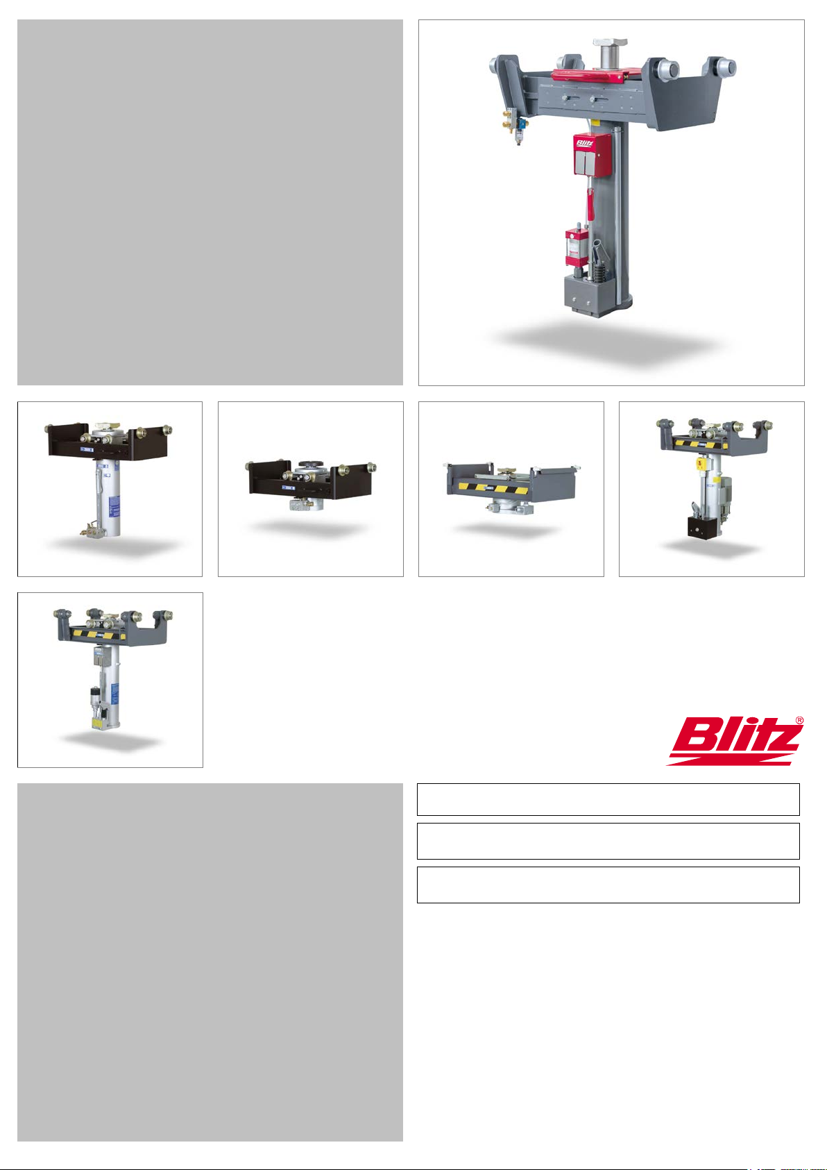
Component overview for all series
[1]
Tilt protection bar
[2]
Control elements
[3]
Drain valve
[10]
[4]
Manual pump
[9]
[5]
Oil drain plug load stroke
[8]
[7]
[1]
[6]
Compressed air supply
[2]
[7]
Oil dipstick load stroke
[3]
[8]
Oil drain plug retrieval
[11] [4]
[9]
Oil dipstick retrieval
[10]
Piston rod
[5]
[11] Cover
Series:
GHUSE
H
P
E
E
Concerning these operating instructions
These operating instructions apply to several series with three different construction methods:
Hydraulic (-pneumatic) construction
Pneumatic construction
Electrohydraulic construction
• Pictures or text sections marked with the symbols shown above only apply to the jacks of the respective construction.
• Position numbers [1] in the operating instructions always refer to the pictures shown here and the component
overview.
• Cross-references () must be taken into consideration.
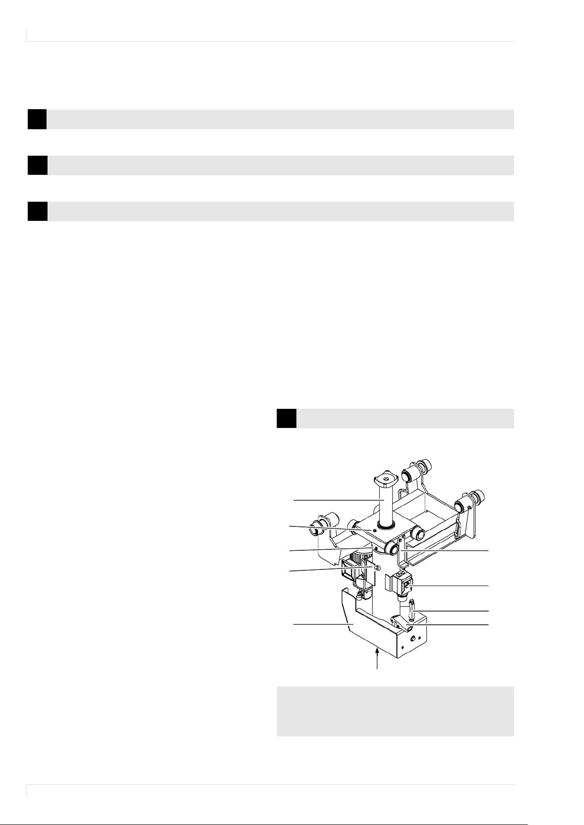
Overview of the Series
The overview shows a variant of each series.
2
/GHUSLE
Operating Instructions for Suspended Jacks
[10]
[1]
[10]
[1]
[2]
[3]
[2]
[6]
[6]
Series:
GWS 2
Series:
GWSK 2
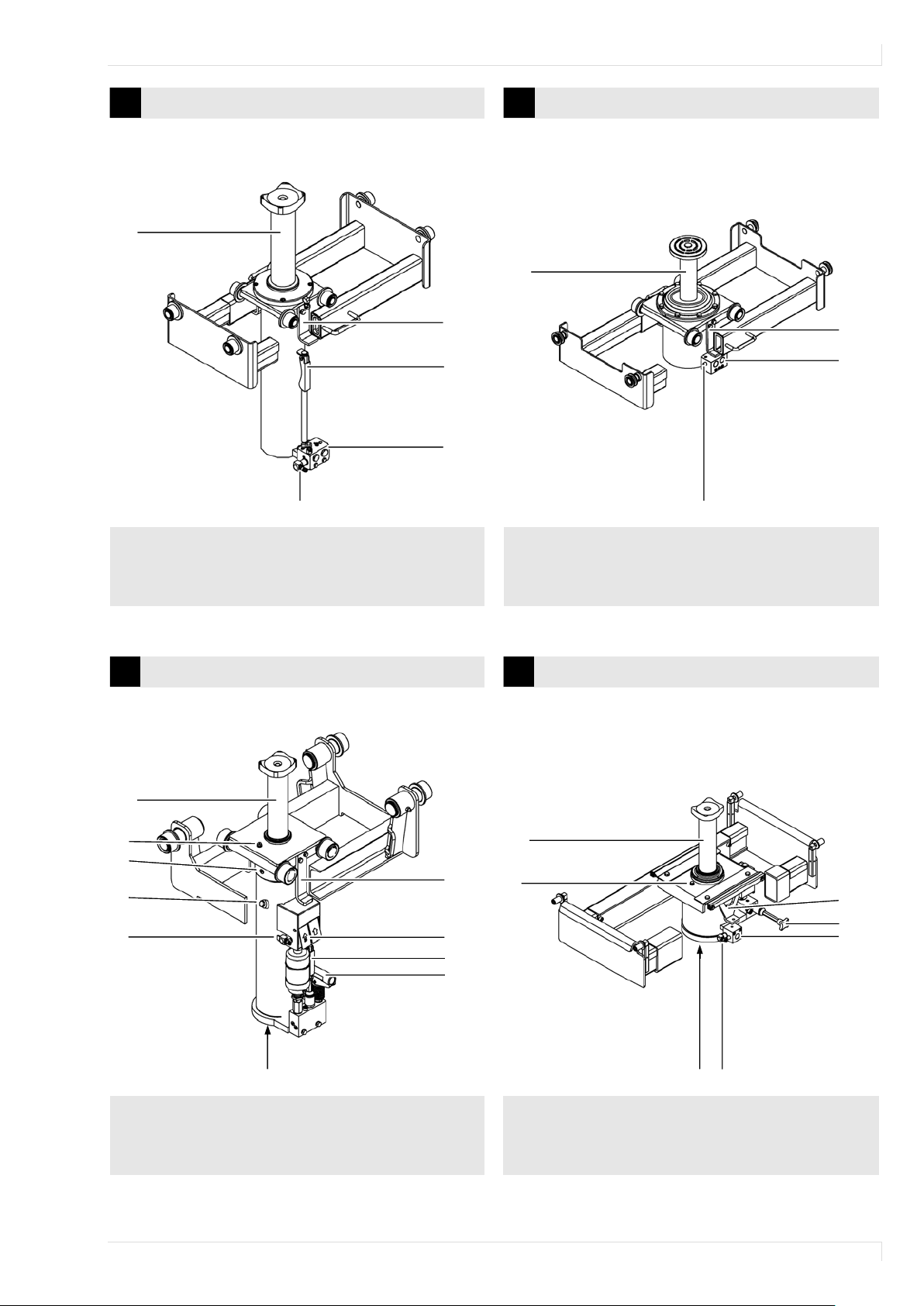
[10]
[9]
[8]
[10]
[7]
[1]
[7]
[1]
[6]
[2]
[3]
[2]
[3]
[4]
[5]
[5] [6]
Series:
GH/GHL
GHUS/GHUSL/GHUST
GHSP/GHLP
Series:
GHUSKTP
P
P
H
H
GWUS 2
GWSKT GWSKTA
GHS/GHSL
GHUSP/GHUSLP/GHUSTP
3
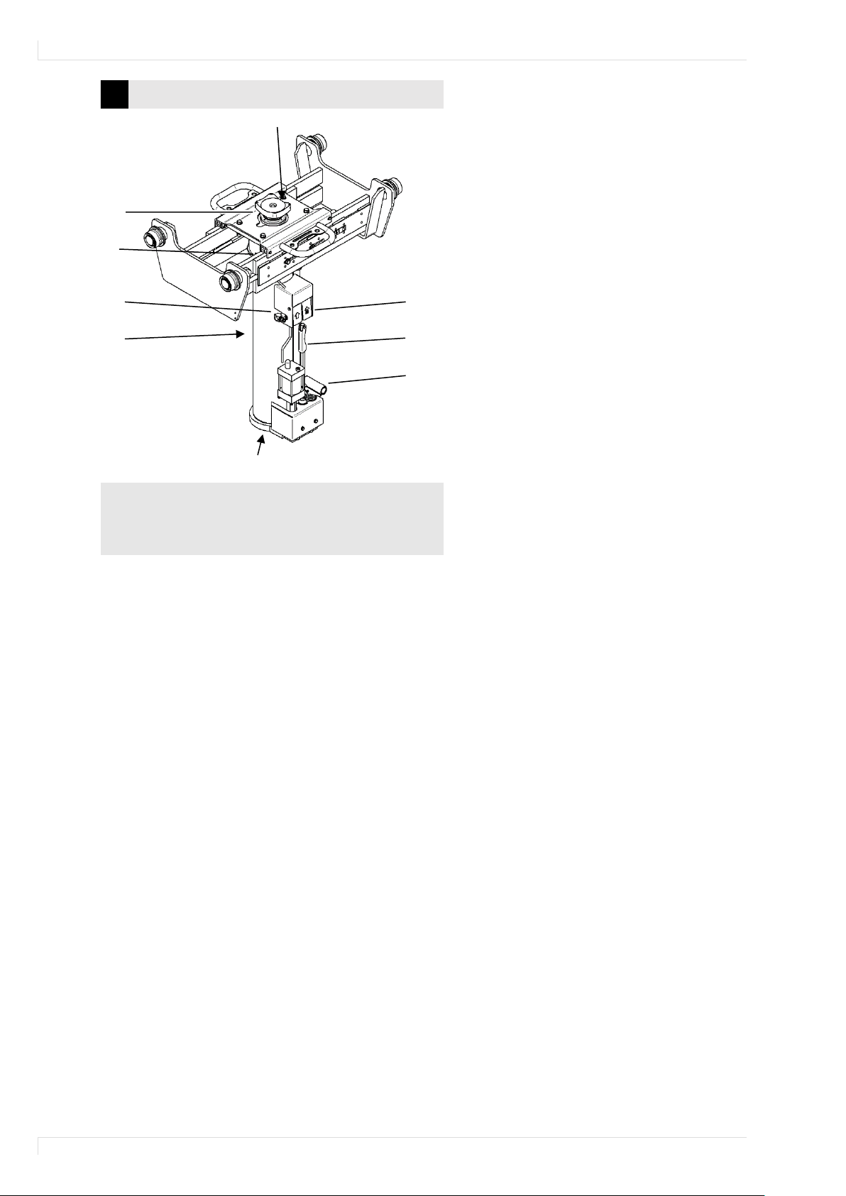
Operating Instructions for Suspended Jacks
[9]
[10]
[8]
[6]
[2]
[7]
[3]
[4]
[5]
Series:
Blitz S 15
H
Vario
4

Operating Instructions for Suspended Jacks
Table of Contents
1 Basic Safety Instructions ........................................................................................................ 6
1.1 Intended Use ................................................................................................................................................. 6
1.2 Basic Measures ............................................................................................................................................ 6
1.3 Safety-relevant Components ...................................................................................................................... 6
1.4 Explanation of Notes ................................................................................................................................... 6
2 Storage ......................................................................................................................................... 6
3 Technical Data ........................................................................................................................... 7
4 Transport, Installation and Assembly ................................................................................. 8
4.1 Make the Lifting Cylinder ready for Operation ........................................................................................ 8
4.2 Install and assemble Jack .......................................................................................................................... 9
4.3 Compressed Air Supply ............................................................................................................................ 12
4.4 Electrical Connection ................................................................................................................................ 12
5 Commissioning ........................................................................................................................ 12
6 Operation ................................................................................................................................... 12
6.1 Load Handling Device ............................................................................................................................... 12
6.2 Supporting Bridges and Trestles............................................................................................................. 13
6.3 Hazard Statements .................................................................................................................................... 14
6.4 Lift, lower and transport Loads ................................................................................................................ 15
7 Maintenance and Repair ....................................................................................................... 16
7.1 Maintenance Intervals ............................................................................................................................... 16
7.2 Perform Function Test............................................................................................................................... 16
7.3 Check Compressed Air Supply ................................................................................................................ 16
7.4 Top up Anti-Rust Oil .................................................................................................................................. 17
7.5 Check the Hydraulic Oil Level .................................................................................................................. 17
7.6 Perform Safety Test ................................................................................................................................... 17
7.7 Changing the Hydraulic Oil ...................................................................................................................... 18
7.8 Replacing Hydraulic Hoses ...................................................................................................................... 18
7.9 Drain the Condensate ............................................................................................................................... 18
7.10 Bleed the Jack ............................................................................................................................................ 18
7.11 Clean or replace the Pneumatic Control Valve ..................................................................................... 19
7.12 Replace Hydraulic Block .......................................................................................................................... 19
8 Troubleshooting ...................................................................................................................... 20
9 Decommissioning and Disposal ......................................................................................... 20
10 EC – Declaration of Conformity .......................................................................................... 21
11 Spare Parts Lists ..................................................................................................................... 22
5

Operating Instructions for Suspended Jacks
H
E
P
1 Basic Safety Instructions
1.1 Intended Use
The jack is intended exclusively for partially lifting vehicles and for transporting vehicle parts
(engine, transmission). Any other use there of shall be considered as not intended use.
Always secure lifted vehicles with supporting bridges/A-frames.
1.2 Basic Measures
The lift may be used only by workshop personnel with corresponding training.
Work on electric, hydraulic, and pneumatic systems may be performed only by specialists.
Observe the operating instructions.
Always keep the operating instructions available at the place of use.
Observe all safety and danger notes on the lift and keep them legible.
The workshop operator must insure that all safety regulations are observed by the workshop
personnel.
Technological modifications of the lift are not permitted.
The operating instructions are a part of the product and must be handed over to a succeeding
user.
Observe the maintenance intervals.
1.3 Safety-relevant Components
• Hydraulic pressure limiting valve
• Hydraulic lowering brake valve
• Tilt protections [1] on the lifting cylinder
• Pull-out safety devices at the undercarriage ( 4.2, Positions A)
• Pressure limiting valve
• Throttle valve
• Tilt protections [1] on the lifting cylinder
• Pull-out safety device at the undercarriage ( 4.2, Positions A)
1.4 Explanation of Notes
DANGER
Risk of death and severe injury
Measures
WARNING
Risk of injury and material damage
Measures
CAUTION
Property damage
Measures
2 Storage
Store the jack in a dry place protected from the weather at an ambient temperature of -10 °C to +50
°C. Contact the manufacturer if storing for more than 6 months.
6

Operating Instructions for Suspended Jacks
GH/GHL, GHS/GHSL,
GHUS/GHUSL/GHUST, GHSP/GHLP,
GHUSP/GHUSLP/SHUSTP
GHUSE/GHUSLE
Blitz S
15
VarioFit
Load capacity
t 4 6
10
15
16
20
30
15
Operating pressure pneumatically
bar
10
10
10
10
10
Operating pressure hydraulically
bar
80
120
199
235
130
Oil capacity container 1
l 5 5 5 5
12
Oil capacity container 2
L
1.2
1.2
1.2
1.3
2.1
2.1
2.1
1.6
Lifting height (L models)
mm
600 (800)
Max lowering speed at rated load
m/s
0.15
GWS 2
GWUS 2
GWSKT
GWSKTA
Load capacity
t 2 3/2.5
4/3.5
2/1.5
3/2.5
Operating pressure pneumatically
bar
12
10
14 8 10
Lifting height
mm
500
420
420
285
345
Max lowering speed at rated load
m/s
0.15
0.15
GHUSKTP
Load capacity
t
4/4
6/6
10/10
12/12
14/14
Operating pressure pneumatically
bar
10
10
10
10
10
Operating pressure hydraulically
Bar
70
105
175
210
245
Oil capacity container
l
4.1
4.1
4.1
4.1
4.1
Lifting height
mm
330
Max lowering speed at rated load
m/s
0.15
H
E
P
H
3 Technical Data
7
Operating Instructions for Suspended Jacks
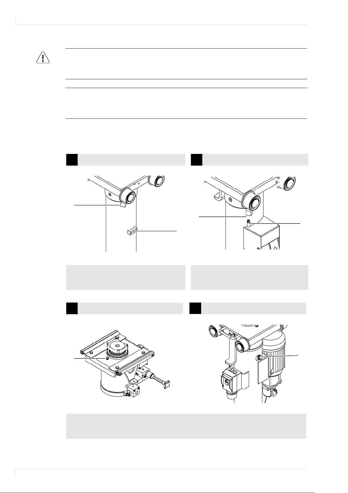
B
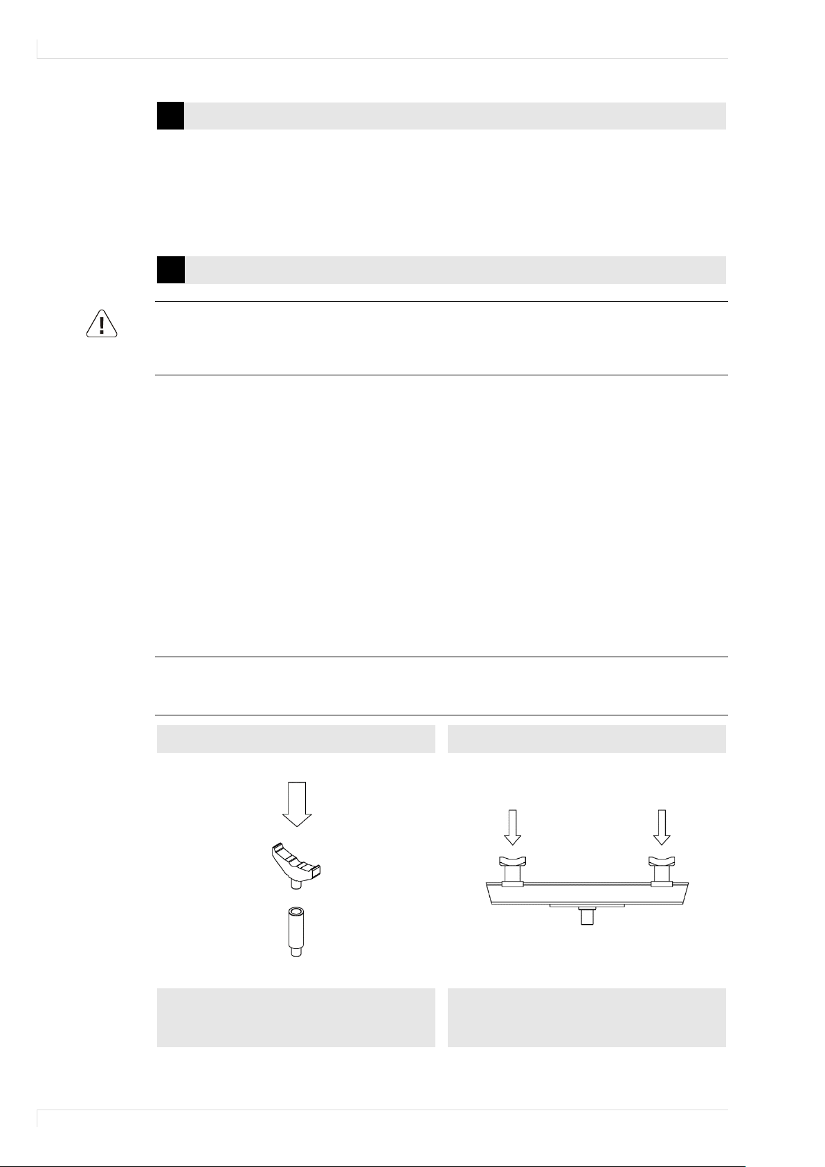
Remove cap A.
Remove cap A.
D
Replace cap D with the supplied ventilation screw.
H
H
H
E
4 Transport, Installation and Assembly
DANGER
Risk of death and severe injury from improper transport
Always transport the lift table with suitable hoisting and transport devices (e.g. forklift or crane).
Never stay under suspended loads.
Safety notes
Hoist the jack at viable spots only.
Move the lifting cylinder horizontally and with the operating elements at the top.
Secure moving and loose parts.
4.1 Make the Lifting Cylinder ready for Operation
Note variants of the hydraulic construction.
Without operating elements
With operating elements
A
In addition, replace cap B with the supplied
ventilation screw.
A
For jacks with retrieval, connect hose C.
C
D
8
Operating Instructions for Suspended Jacks
A
B
Insert undercarriage in rails.
undercarriage and replace the tilt protection bracket on both sides.
4.2 Install and assemble Jack
WARNING
Risk of injury and material damage by crashing jacks
Install jack only on level and solid ground, which has the necessary load-bearing capacity.
Use jack only on load-bearing and parallel rails.
Safety notes
Use jack only with castors that fit the rails.
Only use the jack in the workshop pit or lift for which it was made.
If the distance between the rails of vehicle lifts (e.g. scissor lifts) changes due to alternating load,
additional fuses need to be requested from the manufacturer.
There are five types of undercarriages:
• Undercarriages with sliding axles (adjustable)
• Undercarriages with telescopic carriers (adjustable)
• Single-piece undercarriages (rigid)
• Two-piece undercarriages (rigid)
• Transverse and height-adjustable undercarriages
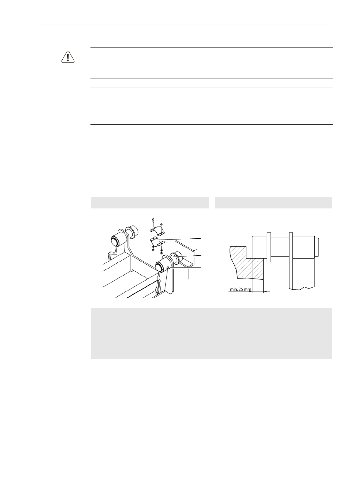
Undercarriages with sliding axles
Standard castors
C
Pull out sliding axes B evenly and set the track width.
Tighten set threaded pins C.
Check the secure support of the castors (standard castors min. 25 mm) over the entire length of
the rails.
Adjust enclosed clamping collars A and attach externally to sliding axles B.
Dismantle the tilt protection bracket [1] on the lifting cylinder, insert the lifting cylinder into the
9
Operating Instructions for Suspended Jacks
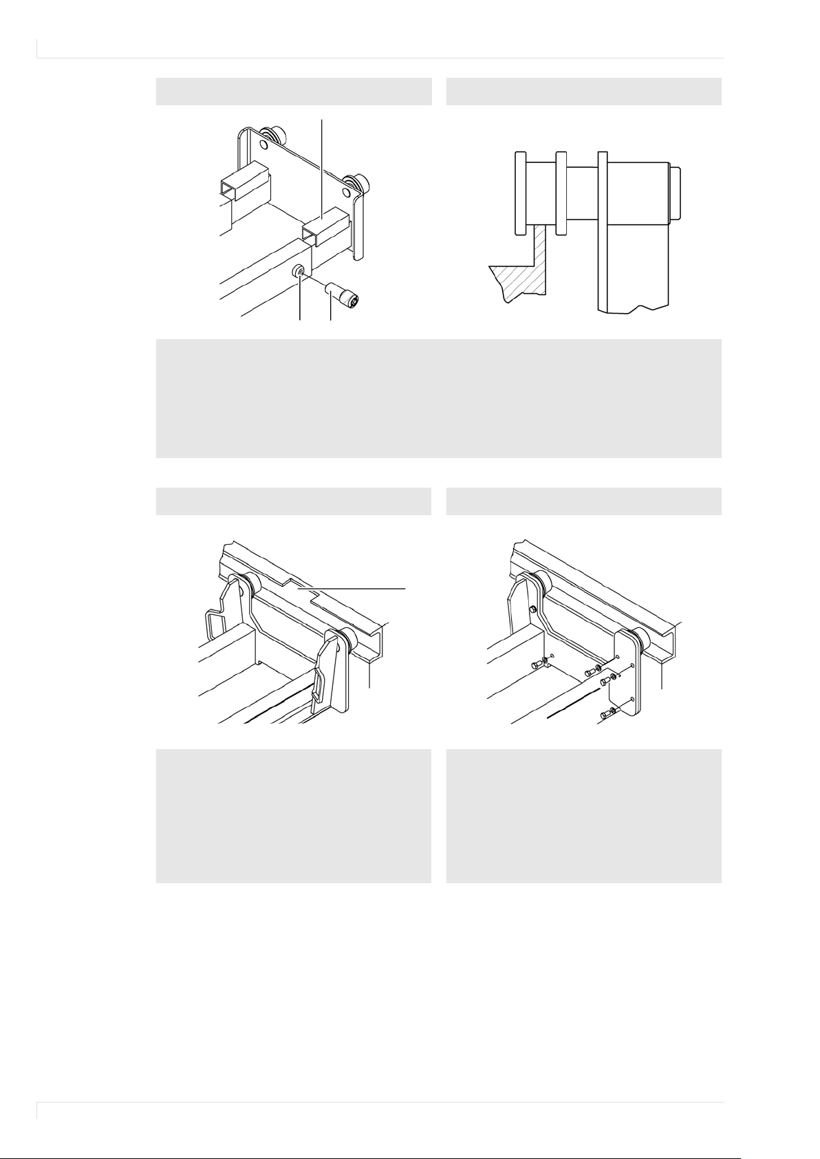
Undercarriages with telescopic carriers
C
B
A
Insert undercarriage in rails and set track width.
undercarriage and replace the tilt protection bracket on both sides.
Single
Two
E
Insert undercarriage via installation opening E
Dismantle the tilt protection bracket [1] on the
protection bracket on both sides.
Insert undercarriage components in rails and
Dismantle the tilt protection bracket [1] on the
protection bracket on both sides.
Remove threaded pins A and drill hole B to 8 mm.
Install threaded pins A with thread outwards and tighten.
Check the secure support of the castors (standard castors min. 25 mm) over the entire length of
the rails.
Adjust and place U profiles C.
Dismantle the tilt protection bracket [1] on the lifting cylinder, insert the lifting cylinder into the
-piece undercarriages
-piece undercarriages
Special castors
10
into rails.
Check the secure support of the castors
(standard castors min. 25 mm) over the entire
length of the rails.
lifting cylinder, insert the lifting cylinder into
the undercarriage and replace the tilt
firmly connect with enclosed screws.
Check the secure support of the castors
(standard castors min. 25 mm) over the entire
length of the rails.
lifting cylinder, insert the lifting cylinder into
the undercarriage and replace the tilt
Operating Instructions for Suspended Jacks
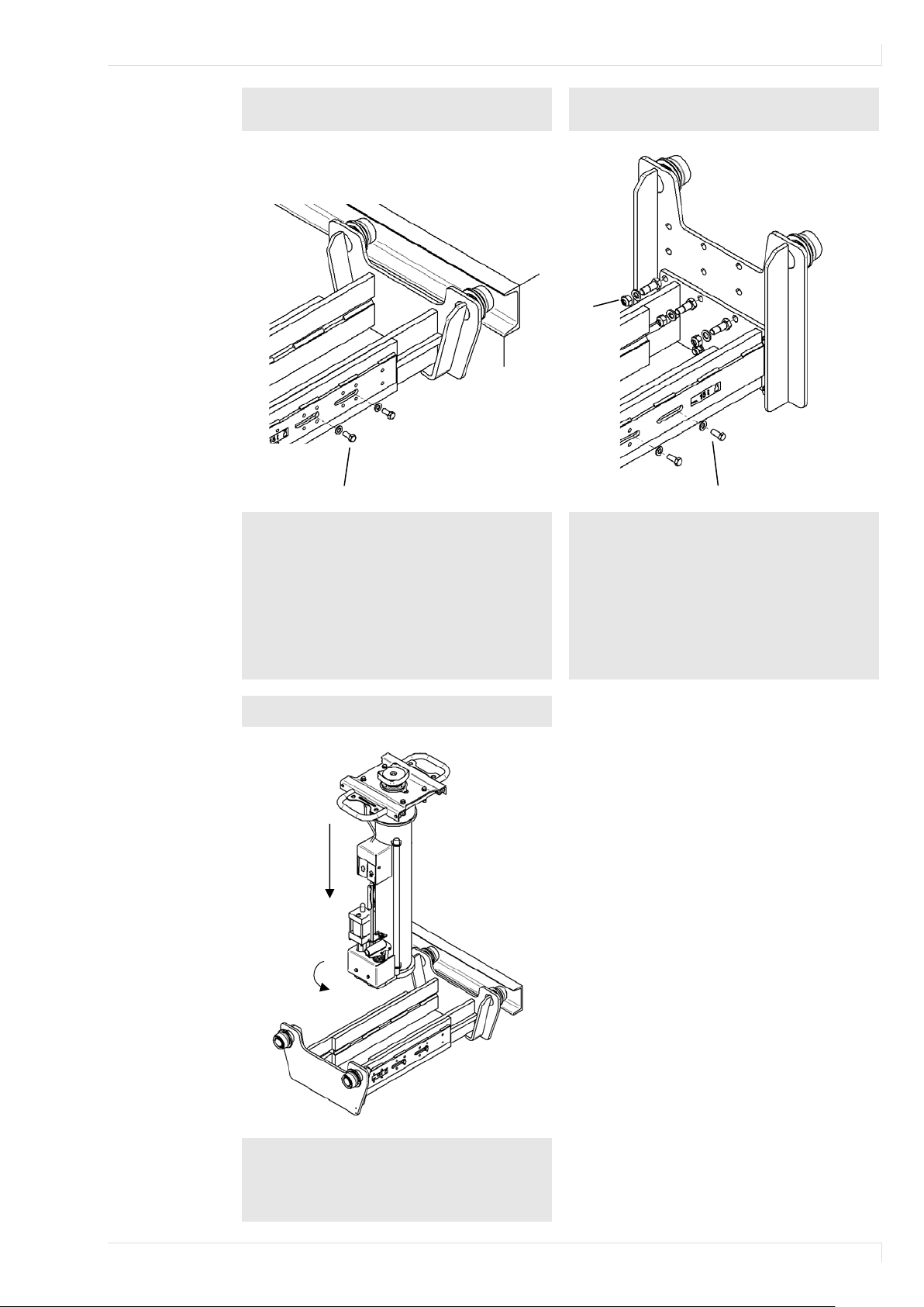
Transverse and height
undercarriage
B
A A
Insert undercarriage in rails and set track
Secure the undercarriage width with screws A
Screw side plates to desired height on the
cure the undercarriage width with screws A
(2 pcs. per side) to 30 Nm.
Lift the jack into the undercarriage and lower
Set jack down on the undercarriage
A
B
Transversely adjustable undercarriage
width.
Check the secure support of the castors
(standard castors min. 25 mm) over the entire
length of the rails.
(2 pcs. per side) to 30 Nm.
-adjustable
undercarriage.
Tighten all screws B with a torque wrench to
80 Nm.
Insert undercarriage in rails and set track
width.
Check the secure support of the castors over
the entire length of the rails.
Se
Transversely adjustable undercarriage
it (A) until the operating element [2] is just
below the guide rails
Turn the jack 90° (B)
11
Operating Instructions for Suspended Jacks
Support plate and extension
Traverse
Lift vehicles at one point.
Carefully lift vehicles at two points.
H
E
4.3 Compressed Air Supply
The compressed air supply must be provided via a maintenance unit consisting of water separator
and pressure reducer. Attach the maintenance unit directly to the jack.
• Supply pressure: max. 10 bar
4.4 Electrical Connection
WARNING
Risk of injury and material damage due to electric shock
The electrical connection and the protective measures in force in the country are to be installed
and checked by a specialist.
The electrical connection must consist of a cable with a five-pin CEE coupling 16 A, which is
connected to a 400V/50Hz mains. A motor-protective circuit-breaker of 3.8 A must be present.
The manufacturer recommends a suitable cable suspension.
5 Commissioning
Before first operation:
Connect compressed air supply or electrical connection to the jack.
Check the hydraulic oil level. ( 7.5)
Perform the safety test. ( 7.6)
6 Operation
6.1 Load Handling Device
Safety notes
Do not stack extensions.
Always use the manufacturer’s original load handling devices with suitable spigots.
12
Operating Instructions for Suspended Jacks
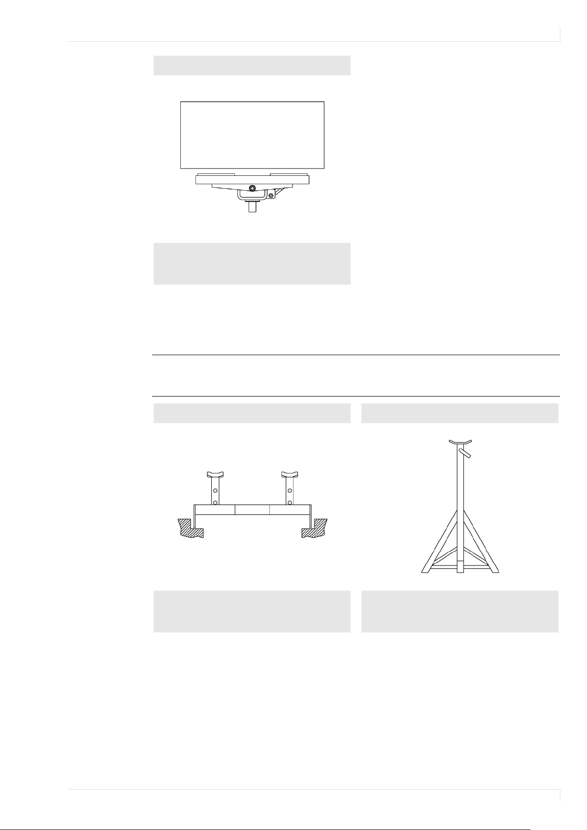
Remove, install and transport vehicle parts
Trestle
For use in workshop pits.
For use on workshop floors,
e.g. under lifts.
Transmission plate
safely.
For poorly accessible load application points on the vehicle use special support plates and an
extension, if necessary. For more information on all load handling devices, contact the manufacturer.
6.2 Supporting Bridges and Trestles
Safety notes
Ensure the secure support of the supporting bridges/trestles over the entire length of the
workshop pit or workshop floors.
Supporting bridge
For more information on all load handling devices, contact the manufacturer.
13
Operating Instructions for Suspended Jacks
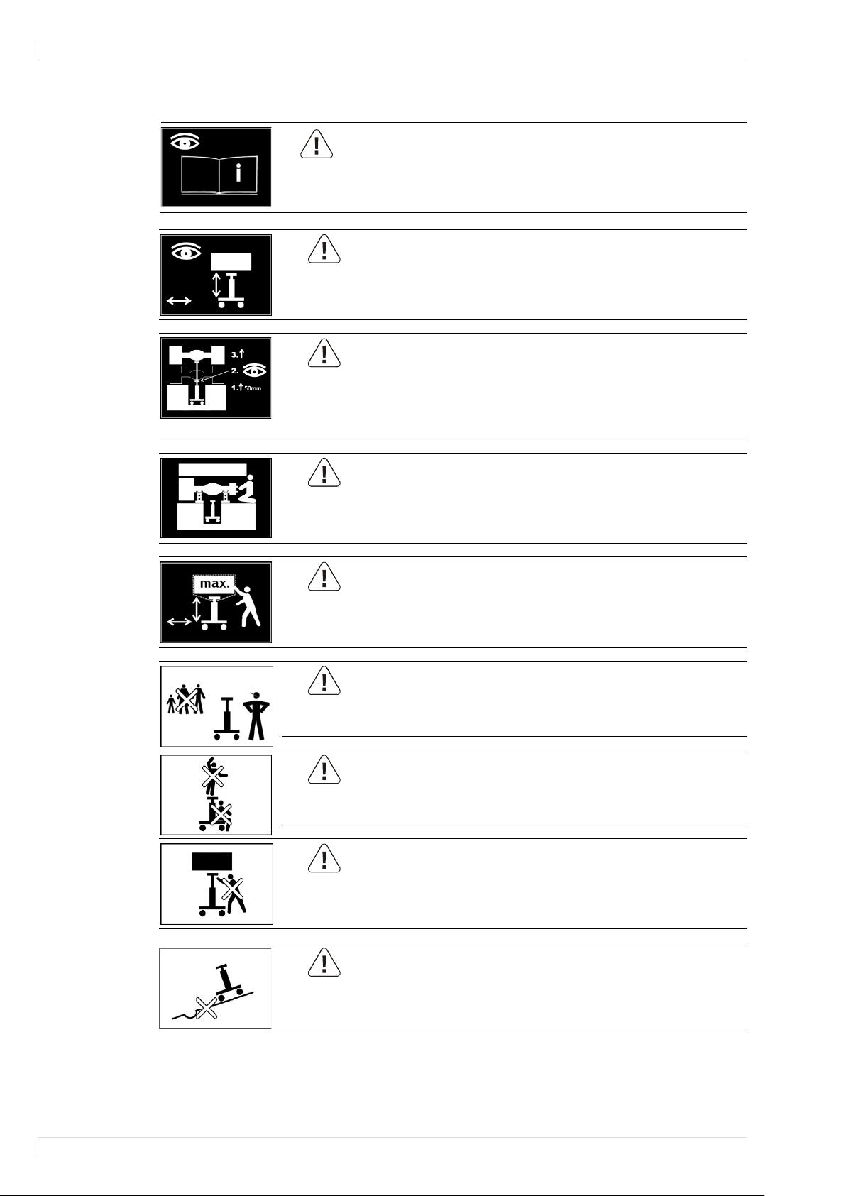
6.3 Hazard Statements
Observe the operating instructions.
Operate the lift only when there is no risk for persons.
Always observe lifting and lowering movements.
Use the lift only in a safety-technologically correct condition.
The safe vehicle support should always be checked after briefly lifting it.
Always use suitable load handling devices.
Attach load handling devices only to horizontal, level and load-bearing
Load application points, which are specified by the vehicle manufacturer.
Always secure lifted vehicles with supporting bridges/A-frames.
Do not exceed the max. load-bearing capacity of the lift.
Secure the vehicle part with chains or belts.
Transport vehicle parts only in lowered condition.
The lift may be used only by workshop personnel with corresponding training.
Lifting of persons and climbing onto the lift and the load are not permitted.
Never stay under suspended loads.
Use jack only on level and firm ground.
CAUTION
DANGER
DANGER
DANGER
DANGER
CAUTION
CAUTION
CAUTION
CAUTION
14
 Loading...