

Page 1

VELOCITY POWER
ACTIVE SUBWOOFER
XLc 200 A
Operating and Installation Instructions
Page 2

Page 3

INTRODUCTION
Proper system planning is vital in order to maximize the
device’s performance and road safety. Plan your installation carefully to avoid compromising performance reliability of the system. Consult an authorized Blaupunkt
dealer for installation or reparation. Read the manual
carefully before operating the device for the rst time.
Safety Notes
Ensure to follow below safety notes during installation
and wiring connection : -
•
Disconnect the negative terminal of the battery.
Refer to the safety notes of vehicle manufacturer.
Ensure positions of the holes are nowhere near the
•
vehicle component to avoid any damage during
drilling.
Incorrect installation may result in malfunc-
•
tion of the device or the car sound system.
Installation and Connection Instructions
•
Select a dry and well-ventilated location to
install the device.
•
The device must not be installed on the rear
shelf, rear seats or exposed locations.
•
The installation location must be suitable for
screw holes and have stable ground support.
Intergrated Fuse
•
The integrated fuse in the device protects
the output voltage and the entire electrical
system in case of malfunction. Do not replace
damaged fuse with higher current.
Switching On/O
•
This device will automatically turn on if audio
signal is detected. The device will also automatically turn o if audio signal is received.
Disclaimer
•
In no event shall Blaupunkt be liable for any
direct, indirect, punitive, incidental, special
consequential damages, to property or life,
improper storage, whatsoever arising out of
or connected with the use or misuse of our
products.
•
USA & CANADA : Product not intended for
sale in the United States and Canada. If
purchased in the U.S. or Canada, this product
is purchased as-is. No warranty, express or
implied is provided in the U.S. and Canada.
Remote Control
1.
Set the GAIN to 200mV (Min), PHASE to NORM., LOW
PASS FILTER to Center before turning on the device.
Set the Bass/Treble of head unit to zero. Set volume
to lower level.
2.
Gradually increase GAIN until the desired sound
eect is achieved or until the sound distribution in
the vehicle is even.
3.
Avoid setting volume of the head unit and GAIN too
high to prevent sound distortion. Ensure speakers
are functioning well to avoid sound distortion too.
4.
Then adjust the LOW PASS FILTER (L.P.F.) to the
desired frequency.
5.
Changing the LPF will change the sound output of
the subwoofer. Continue to adjust GAIN, LPF and
volume until the desiredsetting is found.
6.
Play the music from the head unit while sitting at the
driver and switch between NORM and REV to select
the desired sound output setting. The ideal PHASE
is subjective and varies from one vehicle to another,
depending on the location of the device and the
acoustic characteristics of the vehicle interior.
Recycling and Disposal
Do not dispose of your old unit in the
household trash!
Use the return and collection systems
available to dispose of the old device.
This manual may be updated from time to time without
any notice.
1
Page 4

SPECIFICATION
Subwoofer
Speaker Size : 203mm Dual Voice Coil
•
Voice Coil Size : 49.55mm
•
Impedance : (4.0 + 4.0)ohms
•
Cone Composition : Fiberglass
•
Magnet Type : Ferrite
•
Enclosure Housing Material : Aluminium
•
Enclosure Dimension (LxWxH) : 488 x 251 x 260mm
•
Enclosure Net Weight : 11kg
•
Accessories
Fastener Tapes x2 Screws (M3x6) x2
Remote Controller x1
Amplier
Amplier Technology : Class D
•
Normal Output Power (RMS) : 200W
•
Max. Output Power : 380W
•
Sensitivity (In Car/1W) : 85dB
•
Signal / Noise Ratio (dB) : >90dB
•
Frequency Response : 20Hz-150Hz
•
Low Pass Filter (LPF) : 50Hz-150Hz
•
Voltage : 10V – 14.4V
•
Phase Switch : 0 deg / 180 deg
•
Automatic On/O (Hi & Lo) : High Level Only
•
Screws (M5x10) x4 Screws (M4x20) x4
Cable Holder Bar x1 Mounting Brackets x4
(45 x 22 x 6mm)
4.5m DC Cord x1 Wiring Hardness x1
2
Page 5
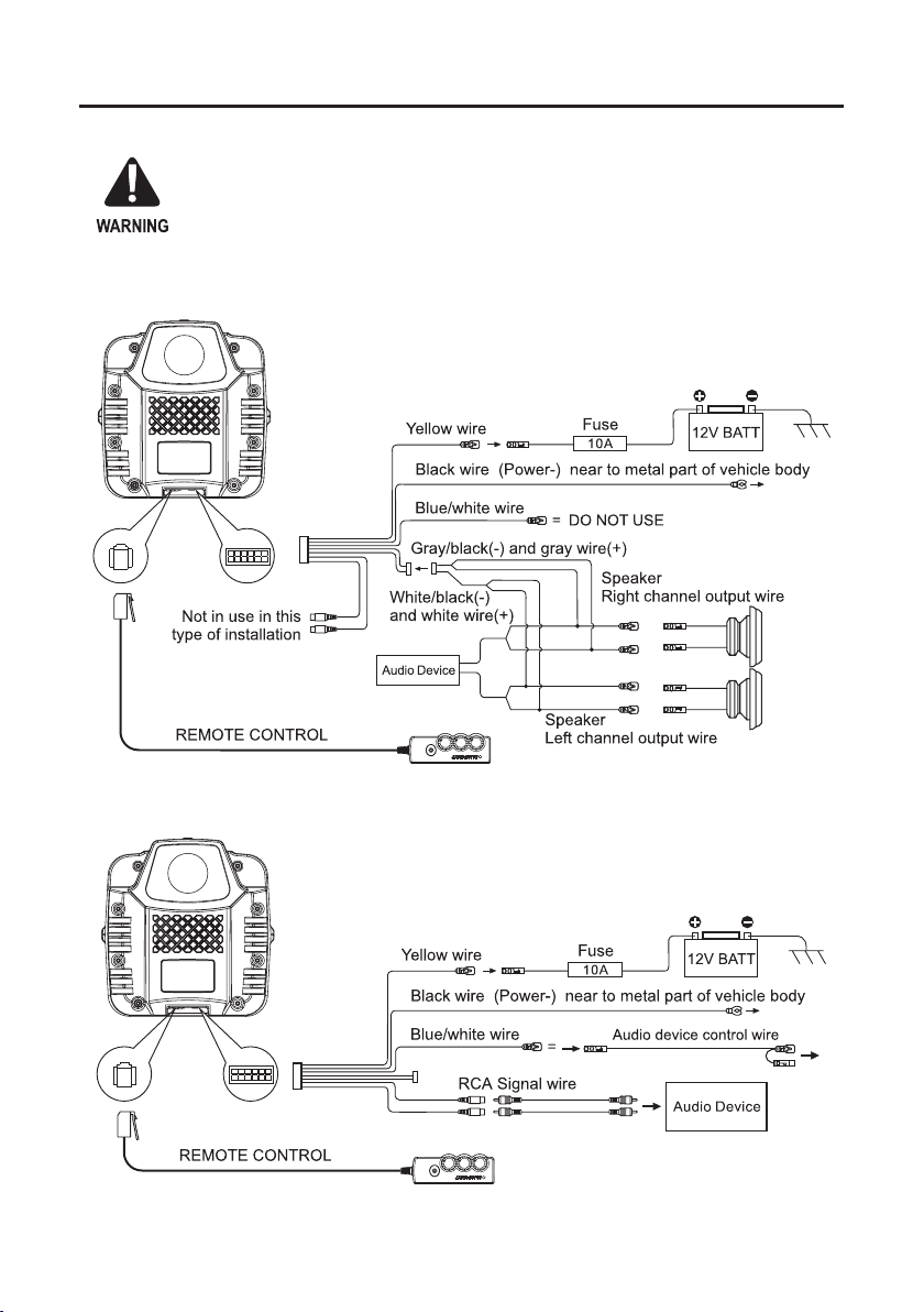
WIRING DIAGRAM
Use the supplied cable and wire harness to connect the outputs correctly by referring to Diagram 1 & Diagram 2.
If your are using only the Low level (RCA) inputs, you must connect the remote wire from the
subwoofer to the system’s head unit so subwoofer will turn on and o with the system. If you will be
using the speaker-level outputs from your head unit, you do not need to connect the remote output.
The subwoofer’s speaker-level inputs will sense voltage on the speaker wires and the subwoofer will
turn itself on. Use only one of the audio inputs, otherwise, it may lead to audio interference.
Diagram 1 (High Level Input)
Diagram 2 (Low Level RCA Input)
3
Page 6

INSTALLATION
Cable Holder Bar
Select an ideal installation location to install the subwoofer. It can be installed by using fastner tapes or mounting
brackets.
a)
Fastener Tapes
Place the fastener tapes on the bottom of the subwoofer and x it on the oor.
b)
Mounting Brackets
Fix the attached mounting brackets to the bottom of the subwoofer by using four (M5x10) screws. Then, mark the
tapping screw’s position on the oor and drill the holes to x the subwoofer by using four (M4x20) screws.
a
b
4
Page 7

TROUBLESHOOTING
If any of the following problem occur, please resort to Troubleshooting for the possible solutions. Consult Blaupunkt
authorized dealer if problem persist.
Problems
Amplier power up
failure
No sound output
Low sound output
Buzzing noise
Squealing noise
interference
Distorted sound output
Amplier temperature
increased
Engine noise (static
sound) interference
Engine noise (alternator
whine) interference
Solutions
Examine if the ground connection is intact.
Examine if remote input has at least 5V DC.
Ensure supplied voltage is minimum 12V.
Examine if fuse is broken and replace if necessary.
Restart the device if protection LED light is on.
Examine fuses and replace if necessary.
Examine ground connection is intact.
Examine if remote input has at least 5V DC.
Examine if RCA audio cables are connected to the right inputs.
Examine if speaker wiring is intact.
Reset Level Control.
Examine the Crossover Control setting.
Observe if the device is still producing noise after turning on and o the amplier.
If yes, examine if the cables are correctly connected and if the cables and radio
are in good condition. Repair or replace if the cables or the radio are not in good
condition.
Ensure RCA connections are properly connected.
Ensure input level of the device matches the signal level of the head unit.
Always set the input level to the lowest.
Examine if crossover frequency is set correctly.
Examine if speaker wire had short-circuit.
Examine the minimum speaker impedance for the amp models is correct.
Ensure good air ventilation around the device. Add external cooling fan if necessary.
Usually caused by poor RCA cable quality, which release noise. Use only the best
quality cables, and route them away from power cables.
Examine if RCA cable are nowhere near or attached to the vehicle chassis.
Examine if head unit is properly connected to the wires.
Page 8

Designed and engineered by Blaupunkt Competence Centre
1 113 20 013 02 01
 Loading...