

Page 1
High-Power
FM/A
/Cassette Receiver with
AutoradiolCassette A
uissance a
Receptor FM/AM/Reproductor de Cassette de
Cartitula Desmontable
R&dio FWAWV’Toca-Fitas
Pot&Ma
Robert Bosch Corporation
Sales
Group-
Blaupunkt Division
2800 South 25th Avenue
Broadview, Illinois 60153
288E8240
corn
F
de
Alta
Face
Alta
Potencia y con
Page 2
FCC WARNING
The equipment has been tested and found to comply with the
protectlon against harmful interference In a resldentlal Installatton This equtpment generates, uses, and can radiate radio frequency energy, and, If not Installed and used
accordance with Instructions. may cause harmful Interference with radio communlcatlons However, there IS no guarantee that radio Interference
lnstallatlon If this equipment does cause harmful Interference to radio or televlslon reception, which can be determlned by turning the equipment off and on, the user IS encouraged
to consult the dealer or an experienced
You are cautroned that any changes or modlflcatlons not expressly approved In this manual could
radloflV technuan
Ikmtts
for help
for a Class Et
device,
pursuant to Pad 15 of the FCC Rules These llmlts are destgned to prowde reasonable
WIII
not occur In particular
void
your authority to operate
th!s equpment.
tn
OWNER’S RECORD
The model and warranty, numbers are located on the top of the unit. Record the serial number in the space provided below. Refer to these numbers whenever you call upon your
Blaupunkt dealer regarding this product.
WarrantyNumber_~ ~~~ _
~.
._~~
FEATURES
Congratulations on your purchase of this Blaupunkt FM/AM/Cassette
player provide the ultimate In sound reproduction
*
Tuner Features:
-
ORC IV Tuner
-
12
FM16
AM Presets
Travelstore FM/AM
-
Automatic and Manual Tuning
Your unit’s detachable front faceplate makes the unit useless to would-be thieves.
l Cassette Features:
-
Autoreverse Cassette Mechanism
-
True Fast-Forward/Rewind
-
Hard Permalloy Tape Head
Receiver
Its Optimum Fteceptlon Control (ORC IV)
*
Audio Features:
-
4 x 30 Watt Max. Integrated
Amplifier
-
Volume/Balance/Fader Controls
-
Adjustable Turn-On Volume-Level
-
Separate Bass and Treble Controls
qlartz
FM and AM Tuner and high-quality, cassette tape
l General Features:
-
Detachable Faceplate for Security
-
Switchable Clock/Function LCD Display
-
Quick-Connect Wire Harness
-
176 x 50 x 153.5 mm (7 x 2 x 6 in.)
DIN Chassis
-
Snap-In DIN Sleeve 8 Mounting Hardware
PRECAUTIONS
*
If your vehtcle was parked In direct sunlight resulting In a conslderable rise tn temperature InsIde the
off before operatlnq your
*
If no power
l
If
l You are cautioned
*
If you have any questlons or problems concerning your unit that are not covered in this manual, please contact your Blaupunkt dealer.
conne&bn
no sound comes from the speakers of a two-speaker system, set the fader control to the center position.
urxt.
is supplied to the unit. check the connections first. If everything is in order, check the fuse.
tha,t
any changes or modifications not expressly approved in this manual could void your warranty.
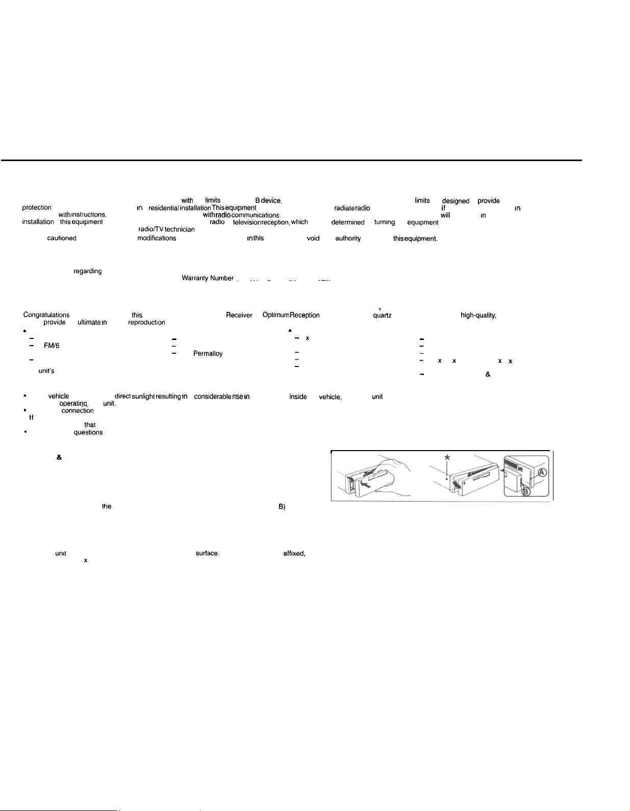
DETACHABLE FACE
Detaching & Attaching the Face: The face of this unit can be detached and taken with you to prevent
it from being stolen.
Detaching the Face: Before detaching the face, be sure to press the PWR Button first. Then press the
REL (Release) Button and detach the face by gently pulling it off as illustrated.
Note: Do not pull it straight out from the chassis. Be sure not to drop the face when detaching it from
the chassis.
Attaching the Face: Apply the right hand side of the face to the chassis by sliding (part B) of the face to (part A) at the front of the chassis. Gently push the left side of the face
against the front of the chassis until it snaps into place.
Note: Make sure that the face is inserted right side up. Do not press against the display window. Do not press hard against the face when attaching it to the chassis, it may be easily
attached with gentle pressure. Do not expose the face to direct sunlight, heat sources such as hot air ducts or leave it in a humid place. Never leave it on the dash board of a vehicle
parked in direct sunlight. where there may be a considerable rise in temperature inside the vehicle.
Affixing Faceplate For Retail Display: The faceplate can be affixed to the unit’s chassis, which is desirable for a retail display, for example. This should only be done in situations
where the
the small bolt (M2.6 x 10) from hardware pack and drive it into the upper hole at the front of the left side of the chassis using a Phillips screwdriver. The bolt will self-thread the hole.
(See above’)
untt
can be accessed from behind the mounting
suriace.
Once the faceplate is afflxed. the release keys cannot be used to remove the chassis. To affix faceplate, obtain
vehcle.
allow the unit to cool
1
Page 3

ELECTRICAL CONNECTIONS AND INSTALLATION
dl~?#&‘zO!
be glad you did!
GENERAL
-
If you’re not confident that you can install the unit correctly, have it installed by a qualified Blaupunkt installation technician.
l
Use this unit only with negative ground 12 Volt (11-16 Volt) direct current (DC).
l
Be
l
If you use the unit’s connector with or without an adapter, make sure that function of the leads (wires) of the connector match the function of the leads in the mating connectors!
l
If your vehicle’s radio wire harness is not compatible with this unit’s harness connector, you can either a. buy an adapter harness at a car audio store -or- b. cut off the unit’s
-
We recommend making and testing all electrical connections before installing the unit.
-
Connect the leads (wires) according to instructions and diagram below unless the speaker’s or amplifier’s manual states that this is O.K.
ELECTRICAL CONNECTION INSTRUCTIONS - ff vou cannot use
1
2.
3
4
5.
6
7
6
9.
10. Attach the faceplate and test the unit.
Once the
SPEAKER
l
Connecting the Speaker Leads
To prevent short circuits or serfous damage to
*
Connect the speaker leads only as indicated in the wiring diagram.
*
Only
-
The unit’s internal amplifier is designed to handle a
l
*
DON’T connect the left and right speaker leads to each other or to the same speakers,
*
DON’T connect the front and rear speaker leads to each other or to the same speakers.
l
l
l
Addlng CD Changer: You can easily play compact discs through this unit by adding the Blaupunkt CDC-RF6
Compact Disc Changer. The space-saving CDC-RF6 easily plugs into the unit’s antenna jack and comes complete with its
own commander control. See your Blaupunkt dealer for details!
To avoid the aggravation of costly mistakes and serious damage that could make you feel this way, please carefully read all of the instructions before you begin. You’ll
RECOMMENDATfONS
sure to detach the faceplate before you start to connect or install the unit.
connector and use a different type of connection.
Disconnect the vehicle battery’s negative
Connect speakers following the guidelines in the SPEAKER CONNECTION section below.
Connect the black (power ground) lead to a grounded metal
common
groundrng
Connect the yellow (constant power) input lead to a source of constant battery power, preferably a terminal to an appropriate slot in the fuse box.
Connect the red (turn-on power) input lead only after the other leads are connected. Be sure to connect the red lead to a positive (+) 12 Volt power terminal that is energized only
when the Ignition key is set to the on position or accessory position,
Cover the ends of any unused leads with electrical tape. This will prevent them from touching the
Reconnect the vehicle’s battery.
Verifv that no fuses have blown,
Plug’the
connectrons
CONNECTtONS
You can connect a speaker (regular, co-axial or
to simply as “speaker”) to each of the units’ four pairs of speaker leads,
point, preferably a non-painted surface under the instrument panel.
harness
Into
the
umt
have been successfully made, you can
terminal
before making connections.
trt-axial
speakers or component speaker system, all hereafter referred
the unit
rrsn sponknrs lhnt hnvn irnpodnncn
the head unit’s stated power level.
DON’T connect two speakers to a single pair of speaker leads (“in parallel”) unless both speakers each have at least 6
ohms impedance.
DON’T connect the negative speaker leads to each other.
DON’T connect the positive speaker leads to each other.
DON’T connect any active speakers (with built-in
rntings of 4 ohms or higher and have power-handling capabilities greater than
4-ohm
amplifiersjto
the unit’s connector with or
part
on the vehicle. We recommend grounding all audio system black ground leads (head unit, CD changer, etc.) to a
begin
to
rnstall
the
unit.
and/or
speakers:
load on each pair of speaker leads.
the speaker leads,
without an
adapter.
vehicle
or each other and causing a shod-circuit and damage to the radio or vehicle.
6-Disc
Page 4

INSTALLATION
Recommendations
l
Carefully choose the mounting location so that the unit won’t interfere with normal driving.
Avord
mounting locations where the unit would be subject to high temperatures, such as from direct sunlight or hot air from the heater, or
l
vibration.
l
The illustration below shows a typical installation, however, you may need to adjust the installation, depending on the unit. If you have questions or need additional installation
hardware, consult your
l
Make sure the unit is firmly anchored (preferably at both front and back)
and does not vibrate.
Mounting the Unit in a Japanese
You
may have
In
thus
Removing the Unit
Use the Release Keys as shown below. Keep them in a safe place in case you need them
,.
In
me
dtffrculty mountrng
case, consult your Blaupunkt dealer.
tuture.
Elaupunkt
dealer.
Car
this unit in some Japanese cars
Mounting The Unit In Most Dashboards
Install the Sleeve in the dashboard.
1
Select and bend the appropriate tabs to hold the sleeve firmly in place.
2
A.B.Attach the Mounting Strap to the underside of the dashboard, using screw.
3
Anach the back of the unit to the mounting strap using the support stem bolt and hardware,
Bend these tabs
I
I
where it would subject to dust, dirt or excessive
MAINTENANCE
Fuse Replacement
When
replacrng
supplred
the fuse, be sure to use one with the correct amperage.
for
thus unrt.
as
thus
could cause
malfunctron
and
serious
whrch
damage to the
will be stated on the fuse case. Never use a fuse that has a stated amperage exceeding the one
unrt.
SPECIFICATIONS
Audio Power
Power Output end Total Harmonic Distortion: 10 watts per channel
total
Othefipe&!cati.oqe
Tuner
FM
Tuning Range:
lntennedrate
FM Mono
Selectivity:
Signal-to-Noise Ratio:
Harmonic distortion at 1
Separation:
Frequency Response:
AM
Tuning Range:
Seek lo
Seek
lntermedrate
SIgnal-to-Noise Ratro
Des!gn and
Soecifications
harmonrc drstortron.
Frequency:
Sensrtrvrtv:
’
sensrtivrty
sensrtivrty:
Frequency:
Specifications
87.5 - 108.0 MHz
07.5
-
107.9 MHz
10.7 MHz
18
dBf
75 dB at 400
65 dB (stereo), 70 dB (mono)
0.7% (stereo), 0.5% (mono)
kHz:
30
dB
30-l 5,000 Hz f 3
531-l ,602
530-1.710
55
35
450
45
subject to change wrthoui
dBuV
dBpV
kHz
dB
kHz
kHz
kHz
dB
nobce.
mrnimum
continuous average output into 4 ohms, 4 channels driven, from
Audio
Speaker Impedance:
Maximum Amp Power:
RMS Power:
Bass Control:
Treble Control:
Cassette
Signal-to-Noise Ratio:
Tape Wow and Flutter:
Tape Frequency Response:
General
Dimensions
Mass.
Power Requirement (neg.
Operating Temperature:
Suppked
(w/o
projecting parts/controls):
Accessones:
grnd.):
4-0
ohms
30 Watts x 4 (at 4 ohms)
lOWattsx4
ilOdB@ 100Hz
ilOdB@
53
dB
0.10%
50-15.000 Hz f 3
170 x 50 x 153.5 mm
7 x 2 x 6 in.
Approx. 1.4 kg (3.0 lb.)
12 V DC car battery
15°F to
12o”F,
l
Unit
l
Mounting Hardware
l
Owner’s Manual in English, French, Spanish and Portuguese
10kHz
dB
-10°C to 50°C
30-15000
Hz with no more than 1%
l
Faceplate
. DIN Sleeve
Page 5

INSTRUCTIONS - GENERAL OPERATION
“Press” means momenfaly press of less than l/Z second
Turning Unit 0”
Vehicle
lg”,f,on must
Turning Unit Off
Press the PWR
Volume
Press + or - to
level IS
tndrcafed
press the other
You can the” gradually
easy
Adjustable Turn-On Volume
Flrsf adfusf
Press and hold the PWR
turn-on volume level is
memorized level, eve” i! the unit was fumed
However, If the volume 8s fumed
0” volume level. the volume will be at the lower level when the unit is turned back on.
Setfing the Clock
Turn the unit
(The display
seconds.) Once the clock stalls blinking. Press the A Button to set the hour, and press
the V
Button
you
can
press the BND Burton.) Press the AUD Button again to activate the clock.
Changing the Information Displayed
*
To change the dlspfsy priority in the radio mode from
clock, press the AUD Button lor two seconds. The display priority changes.
l To change the display temporarily in the radio mode from
function to clock, press and release the AUD Button: After five seconds, the display
changes back to the
Bass and Treble
Press and release as many times as needed AUD
more to
reach the Treble mode. The level is
Buffon or-Button to
Bsla”cs
Press AUD
Display Wtndow
Button to
Fader
Press AUD Button as needed to select the Fader mode The level ot output for front and
back speakers IS lnduxfed I” the
rear
speaker output Press the - Button to decrease the front speaker output
*
Five seconds
the volume
You
can also
alfer FADER t” the AUD Button cycle
AfJD Baton
*
Pressing and
*
Temporary Display Change(s). Bass, Treble, Balance, Fader, Volume.
*
Pressmg the AUD Button for two Seconds changes the display priority between clock
and funchon.
* Pressmg
*
While I” any AUD
volume adjustment mode and priorlfy display.
be on To fur”
Buffon to turn
qutckly tncrease
I” the
Display Wmdow
part
ol the
the volume lo the (maximum) volume level desired when the unit is fumed on.
memonzed.
0”.
Press the
wll
change
to set the minutes. (To change the minute indicator to the nearest hour
priorafy
increase or decrease the level.’
Button
as needed to select the Balance mode The balance IS
Press the + Button to
increase
the
raghf
affer
you complete your adjustments, the
mcde
and fhe
press and release AUD as needed to
Summary
releasing
the AUD Button for tour seconds accesses the time adjustment
mode,
unlf
on. press PWR
the
umf
off
or decrease the volume to the
buffon
adjust
Button
alfer
dlsplav
the AUD Button accesses these modes in this succession:
it no button is pressed for five seconds, the unit returns to the
To make a
before the volume level
the volume I”
for more than
When the unit is fumed on. the volume will be at the
off
when
the
AU0
Button for
two seconds. Ignore this and continue to hold for two more
Information.
speaker
low
fncrease
oulpuf to
Dasplay Wmdow
wll reverl back to the
Buffon
dewed
ftne adfusfmenfs
elfher
of1
volume level is lower than the stored
indlcafed
the
dwppears
dIrecton,
two
seconds. The unit turns
while the volume was at a higher level.
seconds until the clock starts blinking.
cloCk to luncfion 01
Buffon to
I” the Display Window. Press
the letf speaker
desired
level
Press the + Buffo” to decrease the
unit
Driorlfv
ret&” to iOLUME, which
level The volume
to the volume level,
from the
prease
function
lndlcafed
or press the
dwplay
adfusfmenf
oft
and the
function
maklng
CloCk to
select the Bass mode, once
output
*
*
wll automatically
display, clock or function.
appears
mode.
or
return to
Tum-
(:OO).
the
I” the
-
RADIO OPERATION
Band
Selection
Press the BND
Automatic Stereo/Mono Reception Adjustment
When a” FM stereo program with a signal strength of at least 50 dBf is tuned in the
slereo ~“alcator ( a )
and
co”veRs to the
Display
Automatic Seek Tuning
Select the
station. To stop seeking and return to the
the A or V buttons. If the frequency is already stored on a preset button on the active
band, the preset number will appear briefly.
Manual Tuning
Select the desired band. To begin manual tuning, press and hold the A 01 V buffon lot
0.5 seconds. Four seconds after you complete your adjustments, the Tuning Controls
(A V) Buttons revert to Seek Tuning. II the frequency is already stored on a preset button
on
the active band, the preset number will appear brielly.
Travelstore
This
SfafKms.
Select the dewed band. The” press BND Button again
Beginning
stations with strong signals. Once completed. the
trequency.
Selecting Preset Stations
to
Choose the desired band using the BND Button. Press the preset
desired station.
Manually Storing Individual Presets
1. Tune in the desired station using seek 01 manual tuning.
2. Press the preset
confl[m that the station is stored, the audio mutes femporanly. the frequency blinks in
the display. and the preset number appears briefly.
+
CASSETTE PLAYER OPERATION
Casseffe Tape Play:
. Insert casseffe
the tape exposed is lacing to the right side and
the tape prior to insertion.
*
The insertion of the casseffe will automatically override the radio, and the cassette will
begin to play. When the casseffe deck is being used, the display will indicafe which
direction the tape is going.
. The tape wll continue to play until ejected
Autoreverse Tape Function
. Automatic: When the end 01 the tape (side A or B, program 1 or 2) is reached, the
tape will automatically reverse direction and play the other side of the tape.
*
Manual: To reverse tape direction
Buttons. The change in direcfiw and I” tape program will be
Fast Winding of Tape
No matter which side 01 the tape that is playing:
*
To fast-forward the tape. press the FF Button. The direction
the fast-forwarding.
. To fast-rewnd the fape, press the FR Buffo”. The
oppos~fe
Ejecting The Tape
Press the Cassette
Buff~n
as needed to access the
_
“01s~.
feature allows you to automatically store 6 receivable FM and 6 receivable AM
which IS espeaally handy when you travel lo a different reception area.
appears I” the
the
unlf aufomaf~cally
monaural
dewed
band. Press and release the A or V buffon to seek the next receivable
wifh
fhe last station
lnfo
arrow blinks to
blends the signals, ekmlnaflng the
or “mono”
mcde
recetved
button
on which you want to
Cassette
Door.
conilrm
the last-rewnding.
Eject Button to ejecf the
deswd
band, FMI FMII or AM
Display WIndow
The slereo symbol
prewusly
the unit automatically scans the band for
Note: Make
after
dung
playback, press
tape. The radio will play.
r........ ~~
II the rw,
b,ereo
program IS
“we
and gradually
WIII disappear from
tuned frequency, press the other
for
2
seconds.
unit
returns to
the
previously-tuned
buffo”
store
the station for 2 seconds. To
sure
that the side of
that
all slack has bee” removed from
which the radio will play.
direcflon
the
the
PROG (Program)
conlwmed
arrow
wll blink to
arrow stays on and the
_I~.
that has the
casseffe
in the Display.
the
conlirm
v,ea~
the
with
ot
six
TROUBLESHOOTING GUIDE
The
fOffOw+“g check Will aSSlSf I”
operaflng procedures.
General
NO sound.
lndicsfions do not appear on the
display window.
Radio reception -(Make sure the antenna is connected. extended, and dry inside)
Preset
s1a1ions
are not receivable.
Automatic tuning is not possible.
Travelstore leature does not complete
storing of six stations.
If
the above
For dealer referral or product brochure call 1-600-950-2526
menffoned SOIUIIO”S
Trouble
Trouble
the
COrreCtlO” of mOSf
do “of help to lmpmve the
problems which you may encounter wfh your unit. Before gang through the check list below,
I
*
Adjust the volume wlfh the + button.
*
With a P-speaker system. set the fader control to the center position.
*
Remove the front panel and clean the connectors wfh a
mofon -- NOT a
*
The broadcast is too weak.
*
The broadcast IS
*
Not enough broadcast frequencies are
s~fuaf~o”.
side-to-side mof,on
too
weak.
consult your neatest
-->
Use manual tuning.
recewable.
Blaupunkt
Cause/Sofuffon
cotton
swab and
isopropyl
Cause/Solution
dealer or I” the USAcall l-600-266-2528
refer
back to the
alcohol (90% or
higher)
connection a”d
wfh a” !“Iouf
 Loading...