

Page 1

Page 2

1
Page 3

2
TABLE OF CONTENTS
Monitor overview . . . . . . . . . . . . . . 3
IR remote control overview . . . . . . . 5
Notes for the user . . . . . . . . . . . . 6
Precautionary measures . . . . . . . . . 6
Safety notices . . . . . . . . . . . . . 6
Supplied parts . . . . . . . . . . . . . . 7
Installing the monitor . . . . . . . . . 8
Installing the monitor (mechanical) . . 8
Cables . . . . . . . . . . . . . . . . . . . . . . 9
Operation . . . . . . . . . . . . . . . . . 10
Controlling the interior lighting
(monitor) . . . . . . . . . . . . . . . . . . . 10
Opening the monitor . . . . . . . . . . . 10
Adjusting the position of the
monitor . . . . . . . . . . . . . . . . . . . . 11
Closing the monitor . . . . . . . . . . . 11
Powering on the monitor . . . . . . . . 11
OSD menu . . . . . . . . . . . . . . . . . . 12
IR headphones IVHS-01
(accessory) . . . . . . . . . . . . . . . . . 12
Changing the light bulb . . . . . . . . . 13
Changing the battery in the
remote control . . . . . . . . . . . . . . . 13
Specifications . . . . . . . . . . . . . . 14
IVMR-7002P . . . . . . . . . . . . . . . . 14
IVMR-1042P . . . . . . . . . . . . . . . . 14
English
Page 4
3
MONITOR OVERVIEW (IVMR-7002P Shown)
1 2 3 4
5
10
7
6 8
9
1 11
13
14
12
*Note: Buttons 6-9 are located on
the right side of the display screen
on Model IVMR-1042P.
*
Page 5

Lights on the main unit
Light switch ON
Monitor latch
Vehicle interior lighting switch
Infrared receiver for IR remote
control IVRC-06
Infrared transmitter for IR
headphones IVHS-01 (accessory)
Control button
Navigate in the OSD menu
Control button
Navigate in the OSD menu
Control button MENU
See Instructions / OSD menu
On/off button for the monitor
LCD screen
Extension cable (13 pin)
Adapter cable RCA/jack (13 pin)
Red wire = +12V Ignition
Black wire = Ground
Red RCA plug = Audio In (R)
White RCA plug = Audio In (L)
Yellow RCA plug = Video In
Blue phono plug =
IR pass through
for Blaupunkt DVD
players (DVDME2, DVD-ME3 &
DVD-ME R).
Cable for the interior lighting
(3 wires)
Red wire = Constant +12V
White wire = To the door switch
(Negative Door
Trigger)
Black wire = Ground
AUX Input (use for games)*
Red RCA = Audio IN (R)
White RCA = Audio IN (L)
Yellow RCA = Video IN
*Note: Press TV/Video button on
the remote to switch between AV1
and AUX.
1
2
3
4
5
6
7
8
9
10
11
12
13
14
4
MONITOR OVERVIEW
English
11
Page 6

POWER
On/off button for the monitor.
TV/VIDEO
Input selector: switch between
AV1 and AUX.
VOL arrow button /
(Not used)
MUTE
CH arrow button /
(Not used)
MENU
See Instructions / OSD menu
Battery compartment
15
16
17
18
19
20
21
5
IR REMOTE CONTROL OVERVIEW
15 16 17 18
19
20
21
Page 7

6
NOTES FOR THE USER
Thank you for choosing a Blaupunkt
product. We hope you enjoy using this
new piece of equipment. Please read
these operating instructions before
using the equipment for the first
time.
Precautionary measures
Please observe all the warning
notices, precautionary measures and
maintenance tips contained in these
operating instructions so as to extend
the life of your monitor.
Warning
Video products should never be in
view of the driver. Operation of Video
within view of the driver is illegal.
• Do not place the monitor in the
following positions:
1. Positions in which it could restrict
the driver’s view.
2. Positions in which it could
become a danger to safety (e.g.
hand brake, steering wheel,
gearshift lever and airbag).
• Only operate the device with the
recommended voltage supply of
12 V direct current.
• Do not attempt to open or dismantle
the monitor, since you could suffer
an electric shock as a result.
• Avoid using the monitor in
environments where it is subjected
to dust, dirt or moisture.
• Do not install the monitor in places
where it is subjected to direct
sunlight.
Blaupunkt recommends having all your
video products installed by an
authorized dealer.
Safety notices
Please observe the following safety
notices during installation and while
making the connections.
- Disconnect the negative and positive
terminals of the battery.
- When doing so, please observe the
safety notices provided by the
vehicle manufacturer.
- Before drilling the holes necessary
for mounting the equipment and for
laying cables, please make sure that
concealed cables, the fuel tank and
fuel lines cannot be damaged in the
process!
English
Page 8

7
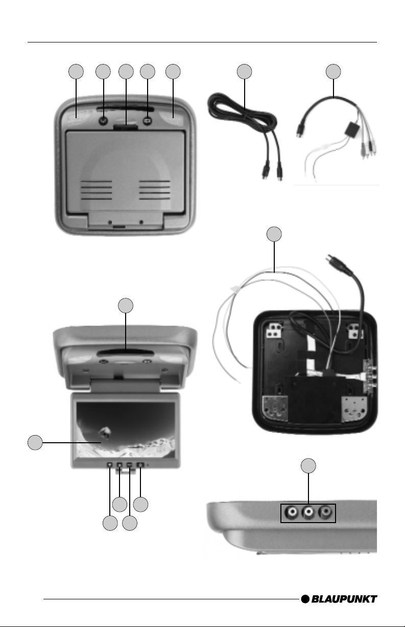
SUPPLIED PARTS
The monitor is supplied with all the
parts listed below. Please check that
the range of parts supplied with your
device is complete. If one of the listed
parts is missing, please contact your
dealer immediately.
• Monitor (including mounting plate
and screws)
• Remote control IVRC-06 with
battery
• 5 m long, 13-pin extension cable
• Connection adapter
(13-pin RCA/jack)
• Operating instructions
Page 9

8
INSTALLING THE MONITOR
Installing the monitor
(mechanical)
Select a suitable position for secure
installation of the monitor:
• The device must not distract the
driver or restrict the driver’s view.
• The ability to enter and get out of the
vehicle must not be impeded.
• The device must not be installed in
such a way that could prevent the
other vehicle components from
functioning properly (e.g. sliding
sunroof).
• Make sure that the device is installed
in a safe and secure position and
that it cannot become detached in
the event of an emergency stop.
• Do not attach the device merely to
the roof liner.
• If you need to drill additional holes,
make sure you do not drill through
the sheet metal of the vehicle’s roof.
• Avoid using the monitor over a
longer period of time while the
engine is off in order to prevent the
battery from becoming discharged.
English
Screws for securing the
mounting plate
Screws for securing the
ceiling-mounted monitor
Page 10

9
INSTALLING THE MONITOR
Interior lighting connection
(3 wires)
Red wire = Constant +12V
White wire = To the door switch
(Negative Door
Trigger)
Black wire = Ground
Warning notice: The operating voltage
cable must be protected with at least a
1.5 A fuse.
Monitor connection (13 pin)
Use the extension cable and the
plug-in adapter cable to connect to
the 12 V supply voltage and an
external video/DVD device:
Red wire = +12V Ignition
Black wire = Ground
Red RCA plug = Audio In (R)
White RCA plug = Audio In (L)
Yellow RCA plug = Video In
Blue phono plug =
IR pass through for
Blaupunkt DVD
players (DVD-ME2,
DVD-ME3 & DVDME R).
Cables
Extension cable
(13 pin)
Adapter cable
11 12
Interior
Lighting
Connection
System
Cable
11
12
Page 11

10
OPERATION
Controlling the interior
lighting (monitor)
There are two switches for the lights:
ON and interior lighting
ON :
This button is used to switch the lights
on/off.
Interior lighting :
If activated, the lights only come on
when the vehicle’s doors are opened.
Opening the monitor
• Push the monitor release latch
to flip down the LCD display.
English
3
2 4
2 4
3
Page 12

11
OPERATION
Adjusting the position of the
monitor
Closing the monitor
Pull the display screen towards you
and up into its base, until it snaps
securely into the locking/releasing
mechanism.
Powering on the monitor
Press the power-on button on the
main unit or the button on the
remote control to switch the monitor
on/off.
9
15
7
6 8
9
15 16 17 18
19
20
21
Page 13

12
OPERATION
OSD menu
Operation
• Press the MENU button on the
display or the MENU button on
the remote control to open the OSD
menu.
• Use the arrow buttons / or
to select the options. After you
press the MENU button or
you can use the arrow buttons to
change the settings.
• Select the "EXIT" option to close
the OSD menu again.
IVMR-7002P OSD Menu
• ZOOM (picture size)
Change the picture height/width
- FULL
- NORMAL
- WIDE
• BRIGHTNESS: To adjust the
brightness
• CONTRAST: To adjust the contrast
• COLOR: To adjust the color
• TINT: To adjust the picture shade
(only for NTSC)
• REVOLVE: To revolve the screen
display
- LEFT - RIGHT:
Mirror horizontally
- UP - DOWN:
Mirror vertically
• RESET PICTURE:
To reset the configured parameters
to the factory default settings.
• EXIT:
To close the OSD menu
IVMR-1042P OSD Menu
• BRIGHTNESS: To adjust the
brightness
• CONTRAST: To adjust the contrast
• COLOR: To adjust the color
• TINT: To adjust the picture shade
(only for NTSC)
• SHARPNESS: To adjust the
sharpness value
• RESET PICTURE: To reset the
configured parameters to the factory
default settings.
• EXIT: To close the OSD menu
IR Headphone IVHS-01
(Optional accessory)
The IR transmitter window must
not be covered up when using the IR
headphones IVHS-01 (Optional
accessory).
Part Number: 7 607 003 590
English
8
8
6
7
20
20
20
ZOOM
BRIGHTNESS
CONTRAST
COLOR
TINT
REVOLVE LEFT-RIGHT
UP-DOWN
RESET PICTURE
EXIT
BRIGHTNESS
CONTRAST
COLOR
TINT
SHARPNESS
RESET PICTURE
EXIT
5
Page 14

13
OPERATION
Changing the dome light
• Detach the monitor from the ceiling
plate (4 screws).
• Remove the 3 screws of the metal
cover (see picture below).
• Take out the old bulb.
•
Put in a new bulb (12 Volts, 3 Watts).
• Reinstall the monitor.
Light bulb specifications
Diameter: 8 mm
Length: 28 mm
Voltage: 12 Volts, 3 Watts
Changing the battery in the
remote control
• Push the button on the battery
compartment to the right
(see A below).
• Pull the battery compartment out
of the remote control (see B below).
• Change the 3 Volt battery
(CR 2025).
Screws for securing the
ceiling-mounted monitor
Metal cover Bulb
21
21
B
A
21
Page 15

14
SPECIFICATIONS
Model IVMR-7002P IVMR-1042P
TFT-LCD Size 7.0" (12.7 cm) 10.4" (26.4 cm)
Aspect Ratio 16:9 4:3
Open to Close 0° to 180° 0° to 180°
Dome Light Yes Yes
Screen Size 7.0" (12.7 cm) 10.4" (26.5 cm)
Pixel Format (WxRGBxH, pixels) 480 x 3 (RGB) x 234 640 x 3 (RGB) x 480
Contrast Ratio 150:1 200:1
Signal System NTSC NTSC
Power Supply 10.0V…16.0V 10.0V…16.0V
Video Input Level Composite Video 0.7Vpp,75 Ohm Composite Video 0.7Vpp,75 Ohm
Audio Input Level 0-0.3 Vrms 0-0.3 Vrms
Operating Temp -20° to +70° C 0° to +50° C
Storage Temp -30° to +85° C -20° to +60° C
Display Method TFT active matrix LCD TFT active matrix LCD
Viewing Area (WxH,mm) 154.08 x 86.58 211.2 x 158.4
Viewing Angle left-right 60°/60° 40°/40°
Viewing Angle top-bottom 60°/30° 20°/25°
Brightness 400 cd/m2 250 cd/m2
Monitor Dimension (WxHxD, mm) 166 x 100 x 6.79 265.0 x 188.8 x 12max
Connector 13 pin DIN cable 13 pin DIN cable
Response Time (msec) 50 40
English
Page 16

Robert Bosch Corporation
Sales Group - Blaupunkt Division
2800 S. 25th Avenue, Broadview, Illinois 60155 U.S.A.
www.blaupunktusa.com
Copyright 2004 by the Robert Bosch Corporation
No portion of this work may be reproduced in any form
without the written consent of the Robert Bosch Corporation Printed in Korea (5/04)
 Loading...