

Page 1
Amplifi er
GTA 480
7 607 792 118
www.blaupunkt.com
Page 2

GTA 480
ENGLISH
Warranty
We provide a manufacturer guarantee for our products
bought within the European Union. You can view the
warranty terms at www.blaupunkt.de or request them
directly from:
Blaupunkt GmbH
Hotline
Robert-Bosch-Str. 200
D-31139 Hildesheim, Germany
Recommendation:
The performance of an amplifi er can only be as good
as its installation. A correct installation increases the
overall performance of your car sound system. The GTA
amplifi er should be installed by a trained person. If you
would to install it yourself, please read these installation
instructions very carefully and allow yourself suffi cient
time for the installation.
In conclusion, allow us a few words about the topic of
health protection:
During the playback of music in your vehicle, please
consider that continuous sound-pressure levels above
100 dB can lead to permanent damages to the human ear
and even to loss of hearing. Using today's high-performance systems and loudspeaker confi gurations allows for
reaching sound-pressure levels above 130 dB.
Safety notes
Please observe the following safety notes
during the installation and connection.
- Disconnect the negative pole of the battery!
Observe the safety notes of the vehicle manufacturer.
- When you drill holes, ensure that you do not damage any vehicle components.
- The cross section of the plus and minus cable may
not be less than 6 mm
- Use cable glands for holes with sharp edges.
- An incorrect installation can result in malfunctions
of the electronic vehicle systems or your car sound
system.
Installation and connection instructions
With respect to accident safety, the GTA 480 must be
secured in a professional way.
When selecting the installation location, select a dry
location that offers suffi cient air circulation for cooling
the amplifi er.
2
(5 A.W.G.).
The GTA 480 must not be installed on rear shelves, rear
seats or other locations that are open to the front.
The installation location must be suitable to accept the
accompanying screws and provide a fi rm support.
The amplifi er power cable must be fi tted with a fuse no
more than 30 cm (1,18") from the battery to protect the
vehicle battery in case of a short circuit between power
amplifi er and battery. The fuse of the amplifi er protects
only the amplifi er, not the vehicle battery.
Use loudspeakers with 2-4 Ω impedance (see table or
installation drawing). Observe the maximum power
handling capacity (music output). Do not connect loudspeakers to earth, use only the referenced terminals.
Amplifi er GTA 480
The amplifi er is suitable for connecting a car sound
system with cinch connections.
For the connection to car sound systems with
ISO connection, use Blaupunkt ISO cinch adapters
(7 607 893 093 or 7 607 855 094).
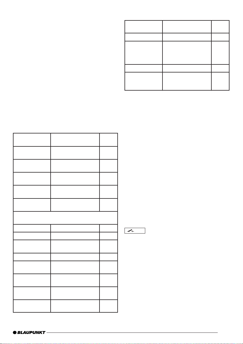
Application options and loudspeaker connection:
Quadro mode
Max. power
Stereo mode
Max. power
Quadro mode
Max. power
Quadro mode
RMS power
Stereo mode
RMS power
Quadro mode
RMS power
RMS power in accordance with CEA-2006
(< 1% dist. / +14.4V)
Frequency response
Signal-to-noise ratio
Signal-to-noise ratio
Distortion factor
(RMS)
Stability
Input sensitivity
Input sensitivity
Direct Aux IN
Low pass fi lter
(Low Pass)
4 x 160 watts / 4 Ω Fig. 4
2 x 425 watts / 4 Ω Fig. 5
4 x 210 watts / 2 Ω Fig. 4
4 x 75 watts / 4 Ω Fig. 4
2 x 210 watts / 4 Ω Fig. 5
4 x 10⁵ watts / 2 Ω Fig. 4
10 Hz - 35.000 Hz
> 95 dB @ RMS
power
> 80 dB @ 1 W /
1 kHz
< 0.03 %
2 Ω (4 Ω in bridged
mode)
0.3 - 8 V
0.3 V
50 - 250 Hz
2
Page 3

GTA 480
High pass fi lter
(High Pass)
Bass boost
Inputs
Outputs
Dimensions
W x H x D (mm)
W x H x D (")
50 - 250 Hz
0 to +12 dB
4x RCA, gold-plated
4x HighLevel speakers
2x Direct Aux Inputs,
3.5 mm (0,35")
stereo
4x Loudspeakers,
gold-plated
352.5 x 53 x 268.5
13.9 x 2.1 x 10.6
Plus / minus connection
- We recommend a minimum cross section of 6 mm
(5 A.W.G.).
- Route commercially available plus cables to the battery and connect via fuse holder.
- Use cable glands for holes with sharp edges.
- Securely fasten commercially available minus cables
to a noise-free earth point (chassis screw, chassis
metal) (not to the minus pole of the battery).
- Scrap the contact surfaces of the earth point until
they are bright and grease with graphite grease.
2
Integrated fuses (Fuse)
The fuses integrated in the amplifi er (Fuse) protect the
power amplifi er and the entire electrical system in case
of an error. If a replacement fuse is used, never bridge
fuses or replace them with a type with higher current.
Connection examples
Connection of the voltage supply ..................fi g. 2
Connection to car sound system
with cinch output ..........................................fi g. 3
Loudspeaker connections ............................fi g. 4/5
Direct Aux Input.............................................fi g. 6, 6a
High-Input ......................................................fi g. 7
+12V
Remote connection of the amplifi er with switchable +12 V
voltage source.
This allows the amplifi er to be switched on and off using
the on/off-switch of the radio device.
Direct Aux Input Connection
Connection options if the car radio has no AUX
input or if the AUX input is already connected
You can directly connect various AF sources (such
as an MP3 player or mobile navigation system) via
a 3.5 mm (0,35") jack plug optionally to the Direct
Aux Input. All signal sources will then be heard simultaneously and their volume must be adjusted
on the respective source device.
Note:
All AF sources must be set to Off during installation and connection!
Installing the jack-plug cable
Please use our 5 m (16.4 ft.) jack-plug cable (Or-
der No. 7 607 001 525) to make the connection.
A special feature is that it has its own On/Off
switch.
Switch position is OFF (•):
During installation and de-installation and when
no AF source is connected.
Switch position is ON (I / II):
Only after an AF source has been connected.
Caution:
When making the connection, always set the vol-
ume control to minimum and switch off the amplifi er.
Level control
The Level control is used to adjust the input sensitivity
of the power amplifi er to the output voltage of your car
sound system preamplifi er output.
The adjustment range is from 0.3 V to 8 V.
If a car sound system of a third party manufacturer is
connected, the input sensitivity must be adjusted corresponding to the manufacturer data.
A few important explanations in this context:
By turning the control clockwise, the input sensitivity of
the amplifi er and, therefore, also the volume increases.
However, this is not a volume control; no further amplifi er output can be achieved in the end position, even if it
may sound like that at the beginning. The system merely
increases the volume faster if the volume control of the
car sound system is turned up.
High-level inputs
The amplifi er is equipped with high-level inputs to permit
connection to radios without preamp outputs (Fig. 7).
This enables direct connection to be made to the radio’s
loudspeaker output.
Loudspeaker connections
(If the amplifi er is to be jumpered, continue with the section "Bridged loudspeaker connections" at this point).
As with every audio component, the correct polarisation of amplifi er and loudspeakers is of essentially
importance for a good bass response. For this reason,
ensure that the positive (+) connection of the amplifi er
3
Page 4

GTA 480
is connected with the positive connection (+) of the
loudspeaker; the same applies to the negative (-) connections. In addition, the left amplifi er channel must
be connected with the left loudspeaker and the right
amplifi er channel with the right loudspeaker.
Bridged loudspeaker connections
The GTA amplifi er can also be bridged for a mono
confi guration. This allows the amplifi er to be used for
one or several subwoofers or mid-range drivers. In this
confi guration, the amplifi er combines the right and left
channel to a single-channel output (mono output).
Note:
The amplifi er can add the right and left signal information only if the right as well as the left RCA connection
were carried out.
Caution:
In a bridge circuit, the amplifi er load must be 4 ohm
or higher. A lower load leads to an overheating or
switch-off of the amplifi er and can cause permanent
damages.
Adjusting the type and range of the frequency
crossovers
With the GTA 480, the type of frequency crossover (i.e.
"Low Pass" or "Hi-Pass") and the desired entry frequency
can be adjusted. For example, if a pair of subwoofers is to
be connected, the low-pass settings shown are required
(Fig. 3). The entry frequency is dependent upon the
frequency range of the loudspeakers (see recommended
frequency range of the loudspeakers).
High-Pass
At a setting of 250 Hz, the amplifi er has a frequency
range of 250 Hz to 35.000 Hz.
Red LED:
Output stage is electronically switched off due to an
error.
Recycling and disposal
Please use the return and collection systems
available to dispose of the product.
Subject to changes.
中文
保修
我們為在歐盟內購買的產品提供製造商保修。您可以訪問
www.blaupunkt.de 查看保修條款,或從以下地址直接索
取:
Blaupunkt GmbH
Hotline
Robert-Bosch-Str. 200
D-31139 Hildesheim, Germany
建議:
放大器的性能直接受到其安裝的影響。正確的安裝可提高您
的汽車音響系統的整體性能。GTA 放大器應該由接受過培訓
的人員進行安裝。如果希望自己安裝,請仔細閱讀這些安裝
說明,並要用充足的時間進行安裝。
最後,我們要談談健康保護的話題:
在裝置中播放音樂期間,請注意聲壓級持續高於 100 分貝可
能對人耳造成永久損失甚至失聰。使用今天的高性能系統和
揚聲器配置,可將聲壓級達到 130 分貝以上。
Low-pass frequency control
This control is active if the switch is in the position
"Low-Pass", and allows for setting the desired entry
frequency.
Example:
At a setting of 150 Hz, the amplifi er has a frequency
range of 10 Hz to 150 Hz.
Bass boost
The bass boost control is used to adjust the bass response of the amplifi er.
The adjustment range is from 0 dB to +12 dB.
Power-on indicator (POWER / PROTECTION)
Green LED:
Output stage on, regular operating status.
4
安全說明
請在安裝和連接期間遵循以下安全說明。
- 將電池的負極斷開!
遵守裝置製造商的安全說明。
- 鑽孔時,請確保不要損壞任何裝置元件。
- 正負極連接線的交接部分面積不能小於 6 平方毫米
(5 A.W.G.)。
- 對於具有尖銳邊緣的線孔要使用電纜襯墊。
- 安裝不正確可能導致電子車輛系統或汽車音響系統工作
不正常。
安裝與連接說明
為了防止出現意外的安全問題,必須以專業方式對 GTA 480
進行安全保護。
選擇安裝位置時,請選擇通風條件良好的乾燥位置,以冷
卻放大器。
Page 5
GTA 480
GTA 480 一定不能安裝在後備箱、後排座位或其他向前開
的位置。
安裝位置必須適合,以便使用隨附的螺絲進行緊固,從而提
供穩固的支撐。
放大器電源電纜必須在電池端配備不長於 30 釐米 (1.18")
的保險絲,以在電源放大器與電池間出現短路的情況下保
護車輛電池。放大器的保險絲僅保護放大器,而不會保護
車輛電池。
使用阻抗為 2-4 歐姆的揚聲器(請參見規格表或安裝圖示)。
遵守最大功率處理能力(音樂輸出)要求。不要將揚聲器接
地,僅使用推薦的終端裝置。
放大器 GTA 480
本放大器適合使用 Cinch 連接來連接到汽車音響系統。
對於使用 ISO 連接來連接到汽車音響系統的情況,請使用
Blaupunkt ISO Cinch 適配器 (7 607 893 093 或 7 607
855 094)。
應用選項和揚聲器連接:
四聲道模式
最大功率
立體聲模式
最大功率
四聲道模式
最大功率
四聲道模式
RMS 功率
立體聲模式
RMS 功率
四聲道模式
RMS 功率
符合 CEA-2006 的 RMS 功率
(<1 % dist./ +14.4 伏)
頻響
信噪比
信噪比
畸變因數 (RMS) < 0.03%
穩定性
輸入敏感度
輸入敏感度
(直接 Aux 輸入)
低通濾波器
(低通)
4 x 160 瓦 / 4 歐姆 圖 4
2 x 425 瓦 / 4 歐姆 圖 5
4 x 210 瓦 / 2 歐姆 圖 4
4 x 75 瓦 / 4 歐姆 圖 4
2 x 210 瓦 / 4 歐姆 圖 5
4 x 10⁵ 瓦 / 2 歐姆 圖 4
10 赫茲 - 35,000 赫茲
> 95 分貝 @ RMS 功率
> 80 分貝 @ 1 瓦 /
1 千赫茲
2 歐姆 (在橋接模式中為
4 歐姆)
0.3 - 8 伏
0.3 伏
50-250 赫茲
高通濾波器
(高通)
低音增強
輸入
輸出
尺寸
W x H x D (毫米)
W x H x D (英寸)
50-250 赫茲
0 至 +12 分貝
4x RCA,鍍金
4x 高級揚聲器
2x 直接 Aux 輸入,3.5
毫米 (0.35") 立體聲
4x 揚聲器,鍍金
352.5 x 53 x 268.5
13.9 x 2.1 x 10.6
正極/負極連接
- 我們建議最小交接面積為 6 平方毫米 (5 A.W.G.)。
- 通過保險絲座將商用正極接線纜連接到電池。
- 對於具有尖銳邊緣的線孔要使用電纜襯墊。
- 將商用負極連接線纜安全地固定到無噪音的接地點(底
盤螺絲、底盤金屬)(不是電池的負極)。
- 對接地點的接觸面進行拋光,直到表面光亮為止,並使
用石墨潤滑劑進行潤滑處理。
集成保險絲
放大器中集成的保險絲可在出現錯誤的情況下保護功率放大
器和整個電子系統。如果要使用其他保險絲進行替換,一定
不要橋接保險絲,或使用允許更高電流的類型進行替換。
連接示例
電源連接......................................................................... 圖 2
使用 Cinch 輸出連接到汽車音響系統 ....................圖 3
揚聲器連接 ....................................................................圖 4/5
直接 Aux 輸入 ............................................................... 圖 6, 6a
高保真輸入 ....................................................................圖 7
+12V
使用可切換的 +12 伏電壓電源的放大器遠端連接。
通過使用無線收音機裝置的開關開啟和關閉放大器。
高保真輸入
放大器配備了高保真輸入端子,可在不使用前置放大輸出的
情況下連接到無線收音機(圖 7)。
通過採用這種方式,就可以直接連接到無線收音機的揚聲
器輸出。
5
Page 6

GTA 480
直接 Aux 輸入連接
汽車收音機沒有
的連接選項
可以通過使用 3.5 毫米 (0.35") 插頭將各種 AF 音源
(如 MP3 播放器或移動導航系統)直接連接到直接
Aux 輸入。隨後將同時聽到所有信號源,其音量必須在
各自的源裝置上進行調整。
注意 :
在安裝和連接期間,必須將所有 AF 音源設置為關閉!
安裝插頭線
請使用我們提供的 5 米(16.4 英尺)插頭線(定購編號
7 607 001 525)進行連接。
此插頭線具有特殊的功能,即自身帶有 On/Off 開關。
開關位置為 OFF (•) :
安裝和拆卸期間以及沒有連接 AF 音源時。
開關位置為 ON (I / II) :
僅在連接了 AF 音源之后
警告 :
進行連接時,請始終將音量設置為最小,並關閉放大
器。
AUX
輸入或
AUX
輸入已經連接情況下
級別控制
級別控制用於調整功率放大器對您的汽車音響系統前置放大
器輸出的輸入敏感度。
調整範圍從 0.3 伏到 8 伏。
如果連接的是第三方製造商的汽車音響系統,必須調整輸入
敏感度,以與製造商數據相對應。
此外,放大器左聲道必須與左側揚聲器連接,放大器右聲道
必須與右側揚聲器連接。
橋接揚聲器連接
GTA 放大器還可以進行橋接,以用於單聲道配置。這樣就可
以將放大器用於一個或多個低音炮或中頻激勵器。在這種配
置中,放大器將左右聲道組合為單聲道輸出。
注意 :
只有在進行了左右 RCA 連接的情況下,放大器才能夠添加
左右信號。
警告 :
在橋電路中,放大器負載必須為 4 歐姆或更高。更低的負載將
導致放大器過熱或關閉,可能會導致永久性傷害。
調整頻率混合器的類型和範圍
對於 GTA 480,頻率混合器的類型(即“低通”和“高
通”)以及所需的輸入頻率都可以進行調整。例如,如果
要連接一對低音炮,則需要此處給出的低通設置(圖 3)。
輸入頻率依賴於揚聲器的頻率範圍(請參見揚聲器的建議
頻率範圍)。
高通
設置為 250 赫茲時,放大器的頻率範圍為 250 赫茲到 35,000
赫茲。
低通頻率控制器
如果開關的位置為“低通”,將啟動此控制器,並允許進行
所需的輸入頻率設置。
示例 :
設置為 150 赫茲時,放大器的頻率範圍為 10 赫茲到 150
赫茲。
此上下文中的一些重要說明:
通過順時針旋轉控制器,放大器的輸入敏感度以及音量將
提高。
不過,這並不是音量控制器;在終點位置無法實現進一步的
放大器輸出;甚至輸出效果可能與在開始位置時一樣。僅在
汽車音響系統的音量控制器開大的情況下,系統才能較快
地提高音量。
揚聲器連接
(如果放大器要進行跳線,請跳到“橋接揚聲器連接”部
分。)
對於每個音頻元件,為了得到良好的低音效果,正確區分放
大器和揚聲器的極性至關重要。因此,請確保放大器的正極
(+)) 與揚聲器的正極 (+) 連接;對於負極 (-) 也是如此。
6
低音增強
低音增強控制器用於調整放大器的低音效果。
調整範圍為 0 分貝到 +12 分貝。
電源指示器 (POWER / PROTECTION)
綠色 LED :
輸出階段,常規操作狀態。
Page 7

GTA 480
紅色 LED :
由於錯誤而以電子方式關閉輸出階段。
回收與處置
請使用回收系統處置此產品。
可能隨時發生更改。
한국어한국어
보증보증
유럽 공동체 (EU) 내의 지역에 제공된 제품에 대해서는
제조업체 보증이 제공됩니다. 보증 조항에 관한 내용은
www.blaupunkt.de 를 참조하거나 다음 주소로 직접 요
청하십시오:
Blaupunkt GmbH
Hotline
Robert-Bosch-Str. 200
D-31139 Hildesheim, Germany
권장 사항권장 사항:
앰프를 올바르게 설치한 경우에만 최상의 성능을 얻을 수
있습니다. 올바르게 설치하면 카 사운드 시스템의 전반적
인 성능이 향상됩니다. 반드시 숙련된 기술자가 GTA 앰프
를 설치해야 합니다. 사용자가 직접 앰프를 설치하려면 설
치하기 전에 충분한 시간을 갖고 설치 설명서를 주의해서
읽어보시기 바랍니다.
마지막으로,
있습니다.
자동차에서 음악을 재생할 때 지속적으로 음압 레벨을 100
dB 이상으로 유지하면 청각에 영구적인 손상을 입거나 청
력을 잃을 수 있습니다. 최신 고성능 시스템과 라우드스피
커 구성을 사용하면 음압 레벨이 130 dB 이상까지 도달
할 수 있습니다.
안전 정보안전 정보
배터리의 음극을 분리하십시오! 차량 제조업체의 안전 배터리의 음극을 분리하십시오! 차량 제조업체의 안전
-
정보를 준수하십시오.정보를 준수하십시오.
- 구멍을 뚫을 때에는 차량의 부품이 손상되지 않도록 주
의하십시오.
- 양극(+)/음극(–) 케이블의 단면적은 6 mm
합니다 (5 A.W.G.).
- 모서리가 날카로운 구멍에는 케이블 그랜드를 사용하
십시오.
- 기기를 올바르게 설치하지 않으면 차량의 전기 시스템
또는 카 사운드 시스템이 고장날 수 있습니다.
설치 및 연결 지침설치 및 연결 지침
안전 사고와 관련해서 반드시 GTA 480 을 전문적인 방식
으로 단단히 고정시켜야 합니다.
설치 위치를 선택할 때에는 앰프를 냉각시킬 수 있도록 통
풍이 잘 되는 건조한 위치를 선택합니다.
부상 방지부상 방지를 위해 반드시 주의해야 할 사항
본 기기의 설치 및 구성 중에는 다음의 안전 정
보를 반드시 준수하십시오.
2
이상이어야
GTA 480 은 차량의 뒷좌석 선반, 뒷좌석 또는 전면이 개방
된 다른 위치에 설치해서는 안됩니다.
설치 위치는 제품에 동봉된 나사를 장착할 수 있고 기기를
단단히 지탱할 수 있는 곳이어야 합니다.
앰프 전원 케이블은 전원 앰프 및 배터리 사이의 회로가 단
락된 경우 차량 배터리를 보호할 수 있도록 배터리에서 30
cm (1.18") 이상 간격을 두고 퓨즈에 연결해야 합니다. 앰
프의 퓨즈는 차량 배터리가 아닌 앰프만을 보호합니다.
2-4 Ω 임피던스를 지원하는 라우드스피커를 사용하십시오
(표 또는 설치 그림 참조). 또한 최대 전원 취급 용량을 준
수하십시오(음악 출력). 라우더스피커를 접지 연결하지 말
고 레퍼런스 단자를 사용하십시오.
GTA 480
본 앰프는 신치 연결을 통해 카 사운드 시스템에 연결하
기 적합합니다.
ISO 연결을 사용하여 카 사운드 시스템에 연결하려면
Blaupunkt ISO 신치 어댑터를 사용하십시오 (7 607 893
093 또는 7 607 855 094).
앰프앰프
애플리케이션 옵션 및 라우드스피커 연결:애플리케이션 옵션 및 라우드스피커 연결:
쿼드로 모드쿼드로 모드
최대 전원
스테레오 모드스테레오 모드
최대 전원
쿼드로 모드쿼드로 모드
최대 전원
쿼드로 모드쿼드로 모드
RMS 전원
스테레오 모드스테레오 모드
RMS 전원
쿼드로 모드쿼드로 모드
RMS 전원
CEA-2006
( <1% dist. / +14.4 V)
주파수 응답주파수 응답
신호-노이즈 비율신호-노이즈 비율
신호-노이즈 비율신호-노이즈 비율
왜곡률 왜곡률 (RMS) <0.03%
안정성안정성
입력 감도입력 감도
입력 감도 직접입력 감도 직접 Aux
IN
로우패스 필터로우패스 필터
(Low Pass)
을 준수하는 을 준수하는 RMS 전원 전원
4 x 160 W / 4 Ω 그림 4
2 x 425 W / 4 Ω 그림 5
4 x 210 W / 2 Ω 그림 4
4 x 75 W / 4 Ω 그림 4
2 x 210 W / 4 Ω 그림 5
4 x 10⁵ W / 2 Ω 그림 4
10 Hz - 35,000 Hz
> 95 dB @
전원
> 80 dB @ 1 W /
1 kHz
2 Ω (브리지 모드에
서 4 Ω)
0.3 - 8 V
0.3 V
50-250 Hz
RMS
7
Page 8

GTA 480
하이패스 필터하이패스 필터
(High Pass)
저음 보강저음 보강
입력입력
출력출력
치수치수
W x H x D (mm)
W x H x D (")
50-250 Hz
0 - +12 dB
4 x RCA, 골드 플
레이트
4 x 고수준 스피커
2 x 직접 Aux 입력,
3.5 mm (0.35")
스테레오
4 x 라우드스피커, 골
드 플레이트
352.5 x 53 x 268.5
13.9 x 2.1 x 10.6
양극(+)/음극(-) 연결양극(+)/음극(-) 연결
- 음극 (–) 단면적을 6 mm2 (5 A.W.G.) 로 설정하는 것
이 좋습니다.
- 일반적으로 사용되는 양극 케이블을 배터리에 연결하
고 퓨즈 홀더를 통해 연결합니다.
- 모서리가 날카로운 구멍의 경우에는 케이블 그랜드를
사용합니다.
- 일반적으로 사용되는 음극 케이블을 노이즈가 없는 접
지 지점(섀시 나사, 섀시 금속)에 단단히 고정시킵니다
(배터리의 음극이 아님).
- 그라파이트 그리스(광물흑연 그리스)를 사용해서 접지
지점의 접촉 표면이 형광을 발하고 광택이 날 때까지
문지릅니다.
통합 퓨즈통합 퓨즈 (Fuse)
앰프에 통합된 퓨즈 (Fuse) 는 오류 발생 시 전원 앰프와 전
체 전기 시스템을 보호합니다. 교체형 퓨즈가 사용된 경우
더 높은 전류를 갖는 퓨즈로 교체하지 마십시오.
연결 예연결 예
전압 공급장치 연결 ............................. 그림 2
신치 출력을 통해 카 사운드 시스템 연결 ..... 그림 3
라우드스피커 연결 .............................. 그림 4/5
직접 Aux 입력 ................................. 그림 6, 6a
고입력 ........................................... 그림 7
전환 가능한 +12 V 전압 소스를 사용한 앰프 원격 연결이
렇게 하면 라디오 기기의 On/Off 스위치를 사용해서 앰프
를 켜고 끌 수 있습니다.
고수준 입력고수준 입력
본 앰프는 프리앰프 출력 없이도 라디오에 연결할 수 있
도록 고수준 입력이 장착되어 있습니다 (그림 7). 이를 통
해 라디오의 라우드스피커 출력에 앰프를 직접 연결할 수
있습니다.
직접 직접 Aux 입력 연결 입력 연결
카 라디오에 카 라디오에
결된 경우 사용할 수 있는 연결 옵션결된 경우 사용할 수 있는 연결 옵션
옵션 품목인 3.5 mm(0.35") 잭 플러그를 통해 다양
한 AF 소스(MP3 플레어 또는 모바일 네비게이션 시
스템)를 직접 Aux 입력에 직접 연결할 수 있습니다.
그러면 모든 신호 소스가 동시에 출력되며 해당 소스
기기에서 음량을 직접 조절할 수 있습니다.
AUX
입력이 없거나 입력이 없거나
AUX
입력이 이미 연 입력이 이미 연
참고:참고:
설치 및 연결 중에는 모든 AF 소스를 OFF 로 설정해
야 합니다.
잭 플러그 케이블 설치잭 플러그 케이블 설치
Blaupunkt 의 5 m (16.4 ft) 잭 플러그 케이블(주문
번호 7 607 001 525)을 사용해서 연결하십시오.
이 케이블에는 자체적인 On/Off 스위치가 포함되어
있습니다.
스위치를 스위치를 OFF 로 설정로 설정 (•):
설치 및 설치 제거 중이나 연결된 AF 소스가 없는
경우.
스위치를 스위치를 ON 으로 설정 으로 설정 (I / II):
AF 소스가 연결된 후후에만.
주의:주의:
연결할 때는 반드시 음량 컨트롤을 최소로 설정하고
앰프의 전원을 꺼두십시오.
레벨 컨트롤레벨 컨트롤
레벨 컨트롤을 카 사운드 시스템 프리앰프 출력의 출력
전압에 맞게 전원 앰프의 입력 감도를 조절하는 데 사용
됩니다.
조절 범위는 0.3 V - 8 V 사이입니다.
제 3 자 제조업체의 카 사운드 시스템을 연결하는 경우
해당 제조업체 데이터에 따라 입력 감도를 조절해야 합
니다.
그 밖의 중요 정보:그 밖의 중요 정보:
컨트롤을 시계방향으로 돌리면 앰프의 입력 감도가 증가
하므로 음량이 커집니다.
그러나 이 컨트롤은 음량 컨트롤이 아니기 때문에 처음에
는 음량이 커진 것처럼 들릴지라도 앰프 출력이 구현된
것은 아닙니다. 카 사운드 시스템의 음량 컨트롤을 조작
한 경우에만 볼륨을 신속하게 조절할 수 있습니다.
라우드스피커 연결라우드스피커 연결
(앰프의 점퍼가 설정된 경우 “브리지 라우드스피커 연결”
절을 참조하십시오)
모든 오디오 컴포넌트에서 탁월한 저음 응답을 얻기 위해서
는 앰프 및 라우드스피커의 극성을 올바르게 연결하는 것
이 중요합니다. 이러한 이유로 인해 앰프의 양극(+) 연결
부를 라우더스피커의 양극(+) 연결부에 연결하고 음극(-)
연결부 또한 같은 방식으로 연결해야 합니다.
8
Page 9

또한 좌측 앰프 채널을 좌측 라우더스피커에, 우측 앰프 채
널을 우측 라우더스피커에 연결해야 합니다.
브리지 라우드스피커 연결브리지 라우드스피커 연결
모노 구성을 위해 GTA 앰프를 브리지 방식으로 연결할 수
있습니다. 이렇게 하면 하나 이상의 서브우퍼 또는 중음
드라이버에 대해 앰프를 사용할 수 있습니다. 이 구성에서
는 앰프의 좌/우측 채널을 단일 채널 출력(모노 출력)에
연결합니다.
참고:참고:
좌/우측 RCA 를 연결한 경우에만 앰프를 통해 좌/우측 신
호 정보를 추가할 수 있습니다.
주의:주의:
브리지 회로에서 앰프 부하는 브리지 회로에서 앰프 부하는 4 Ω 이상이어야 합니다. 이 이상이어야 합니다. 이
보다 낮은 부하를 사용하면 앰프가 과열되거나 전원이 꺼보다 낮은 부하를 사용하면 앰프가 과열되거나 전원이 꺼
져 영구적인 손상이 발생할 수 있습니다.져 영구적인 손상이 발생할 수 있습니다.
주파스 크로스오버 유형 및 범위 조절주파스 크로스오버 유형 및 범위 조절
GTA 480 을 사용하면 주파수 크로스오버(즉, “로우패스”
또는 “하이패스”) 유형과 원하는 입력 주파수를 조절할
수 있습니다. 예를 들어, 서브우퍼 쌍이 연결된 경우 다음
과 같은 로우패스 설정이 필요합니다.
(그림 3). 입력 주파수는 라우드스피커의 주파수 범위
에 종속됩니다(라우드스피커에 대해 권장되는 주파수 범
위 참조).
하이패스하이패스
250 Hz 설정에서 앰프는 250 Hz - 35,000 Hz 범위의 주
파수를 지원합니다.
빨간색 빨간색
LED:
오류로 인해 출력부의 전력이 차단됩니다.
재활용 및 폐기재활용 및 폐기
반드시 반환 및 회수 시스템을 사용해서 제품을
폐기하십시오.
예고 없이 변경될 수 있습니다.
GTA 480
로우패스 주파수 컨트롤로우패스 주파수 컨트롤
스위치가 “Low-Pass” 위치로 설정된 경우 이 컨트롤이 활
성화되고 원하는 입력 주파수를 설정할 수 있습니다.
예:
150 Hz 설정에서 앰프는 10 Hz - 150 Hz 의 주파수 범위
를 지원합니다.
저음 보강저음 보강
저음 보강 컨트롤은 앰프의 저음 응답을 조절하는 데 사
용됩니다.
조절 범위는 0 dB ~ +12 dB 사이입니다.
전원 켜기 표시기 전원 켜기 표시기
녹색 녹색
LED:
출력부가 켜지고, 정상적인 작동 상태를 나타냅니다.
(POWER / PROTECTION)
9
Page 10

GTA 480
Installation, 安裝, 설치설치
Fig. 1
Fig. 2
FUSE
FUSE
SUPPLY
REMOTE
GROUND
25A
CH1
CH2 CH3 CH4
Fig. 3
10
12V
+12V
( FUSE )
+12V
BRIDGE MODE BRIDGE MODE
FRONT
REAR
Page 11

GTA 480
Installation, 安裝,
Fig. 4
FUSE
Fig. 4
FUSE
설치설치
FUSE
4x min. 2 Ω
FUSE
SUPPLY
SUPPLY
REMOTE
REMOTE
GROUND
GROUND
CH1
CH2
BRIDGE MODE
FRONT
CH1
CH2 CH3 CH4
BRIDGE MODE
FRONT
CH3 CH4
BRIDGE MODE
REAR
BRIDGE MODE
REAR
Fig. 5
FUSE
FUSE
min. 2 Ω
SUPPLY
min. 4 Ω
REMOTE
GROUND
CH1
CH2 CH3 CH4
BRIDGE MODE
FRONT
BRIDGE MODE
REAR
min. 2 Ω
min. 4 Ω
11
Page 12

GTA 480
Installation, 安裝,
Fig. 6
7 607 001 525
Fig. 6a
TravelPilot
Lucca
설치설치
MP3
7 607 001 524
FRONT
REAR
AUX-IN
AUX-IN
CH4
CH3
LINE-IN
REAR
CH2
CH1
FRONT
12
7 607 001 525
MP3
FRONT
REAR
AUX-IN
AUX-IN
CH4
CH3
LINE-IN
REAR
CH2
CH1
FRONT
Page 13

GTA 480
Installation, 安裝,
Fig. 7
HIGH LEVEL - INPUT
설치설치
FRONT
REAR
5A
LR
LF
RF
RR
+
–
Only for car radios with bridged output
stage.
僅用於採用橋接輸出的汽車收音機。
브리지 출력부가 있는 카 라디오에만 해당.
HI -
+ - -
LEFT
HI - INPUT
+ - -
LEFT
INPU
T
+
RIGHT
+
GHT
RI
+
+
–
–
+
+
–
–
13
Page 14

GTA 480
14
Page 15

GTA 480
15
Page 16

Service numbers, 服務電話, 서비스 센터 번호서비스 센터 번호
Country: Phone: Fax:
Germany (D) 0180-5000225 05121-49 4002
Austria (A) 01-610 39 0 01-610 393 91
Belgium (B) 02-525 5444 02-525 5263
Denmark (DK) 44 898 360 44-898 644
Finland (FIN) 09-435 991 09-435 99236
France (F) 01-4010 7007 01-4010 7320
Great Britain (GB) 01-89583 8880 01-89583 8394
Greece (GR) 210 94 27 337 210 94 12 711
Ireland (IRL) 01-46 66 700 01-46 66 706
Italy (I) 02-369 6331 02-369 6464
Luxembourg (L) 40 4078 40 2085
Netherlands (NL) 00 31 24 35 91 338 00 31 24 35 91 336
Norway (N) 66-817 000 66-817 157
Portugal (P) 2185 00144 2185 00165
Spain (E) 902 52 77 70 91 410 4078
Sweden (S) 08-7501850 08-7501810
Switzerland (CH) 01-8471644 01-8471650
Czech. Rep. (CZ) 02-6130 0446 02-6130 0514
Hungary (H) 76 511 803 76 511 809
Poland (PL) 0800-118922 022-8771260
Turkey (TR) 0212-335 06 71 0212-3460040
USA (USA) 800-950-2528 708-865-5296
Brasil
(Mercosur) (BR) 0800 7045446 +55-19 3745 2773
Malaysia
(Asia Pacifi c) (MAL) +604-6382 474 +604-6413 640
Blaupunkt GmbH
Robert-Bosch-Str. 200
D-31139 Hildesheim
03.2007
CM-AS/SCS1- 8 622 405 427
 Loading...