

Instrucciones de instalación
Radioteléfono
Antares T60
INSTRUCCIONES DE INSTALACIÓN
E
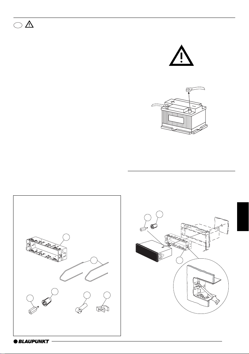
Normas de seguridad
Durante el montaje y la conexión es
imprescindible observar las siguientes
normas de seguridad.
- Desemborne el polo negativo de la
batería.
Observe las normas de seguridad dadas
por el fabricante del vehículo.
- Al perforar agujeros, asegúrese de no
dañar ninguna pieza del vehículo.
- La sección transversal del cable positivo
y del cable negativo no debe ser menor
de 1,5 mm
2
.
- Una instalación incorrecta puede
provocar perturbaciones en los sistemas
electrónicos del vehículo o en la radio.
-¡No conecte a la radio los conectores
ubicados en el vehículo!
- Los cables adaptadores necesarios para
su vehículo los encontrará en el
comercio especializado en artículos de
la marca BLAUPUNKT.
Medföljande
monteringsdetaljer
A
2.
1.
DEUTSCH
ENGLISH
FRANÇAIS
12V
ITALIANO
NEDERLANDS
SVENSKA
D
C
182
53
165
ESP AÑOL
1-20
B
D
C
E
F
A
PORTUGUÊS
53

INSTRUCCIONES DE INSTALACIÓN
3.
A
7 607 621 . . .
Adaptador específico del vehículo, el cual se
puede adquirir en el comercio especializado.
5.
4.
Antenna del teléfono
F
E
Antenna del radio
Antena del teléfono
Una vez instalada la antena, apretar con la
mano la conexión de la radio y apretarla
de vuelta más con unos alicates.
Nota: Para evitar perturbaciones, se
recomienda no tender el cable de la antena
del teléfono cerca de los cables de los
altavoces.
1
/4
Conexión con micrófono “manos libres”
54
10A

6.
INSTRUCCIONES DE INSTALACIÓN
10
10
3
DEUTSCH
ENGLISH
FRANÇAIS
ITALIANO
Conexión con auricular (juego de mano 7 607 570 512)
7.
10A
CD-Changer
Conexión mando a distancia de infrarrojos RCT 07
NEDERLANDS
SVENSKA
ESP AÑOL
PORTUGUÊS
55

INSTRUCCIONES DE INSTALACIÓN
8. 9.
8 601 910 002
1
2
B
1
12V
2
10.
C-1 C-2 C-3
7
10 131619
14
9
6
C
B
A
3
58
2
1
234
345
1
2
C1 C2 C3
1 Line Out LR 7 Handset-AOP 13 Bus - In
2 Line Out RR 8 Handset-Mikro 14 Bus - Out
3 Line Out Masse / Ground 9 Handset-AON 15 nc
4 Line Out LF 10 nc 16 +12V
5 Line Out RF 11 Mikro - In 17 Bus - Masse / GND
6 +12V Amplifier 12 Tel. - NF - Ground 18 AF - Masse / GND
15
18
12
20
14 17
11
5
7
6
8
7
6
8
1nc1 Speaker out RR+
2 nc 2 Speaker out RR3nc3 Speaker out RF+
4Permanent +12V 4 Speaker out RF5Aut. antenna 5 Speaker out LF+
6 Illumination 6 Speaker out LF7 Kl.15/Ignition 7 Speaker out LR+
8Ground 8 Speaker out LR-
AB
C
19 Line In - L
20 Line In - R
56
Equalizer Amplifier
Remote Control
CD-Changer

11 .
INSTRUCCIONES DE INSTALACIÓN
DEUTSCH
ENGLISH
FRANÇAIS
ITALIANO
RR
RF
12V
+
LR
LF
+
+
+
4 Ohm
-
4 Ohm
-
4 Ohm
-
4 Ohm
-
(max. 150 mA)
Relais
Kl. 15 +12V
10A
7
5
3
1
8
6
4
2
Ground
NEDERLANDS
SVENSKA
ESP AÑOL
Illumination
PORTUGUÊS
Modificaciones reservadas!
+12V
12V
57
 Loading...