

Page 1
BLAKESLEE
Division of Blako Inc.
GLASSWASHER
MODEL G-2000-F
OWNERS
MANUAL
1844 South Laramie Avenue
Chicago, IL 60804
Phone (708) 656-0660
Fax (708) 656-0017
www.blakesleeinc.com
service@blakesleeinc.com
1149 Bellamy Road North Unit 19
Scarborough, Ontario Canada M1H1H7
Phone (416) 751-2625
Fax (416) 751-8539
Page 2

INDEX
PAGE
NO.
SPECIFICATIONS 1
SECTION I OPERATION 2
SECTION II DAILY CHECK-OUT 3
SECTION III CLEANING 4
SECTION IV TROUBLE SHOOTING 5
SECTION V PARTS ILLUSTRATIONS 7
WIRING DIAGRAM 16
CLEANING TOOL 18
WARRANTY 19
Page 3
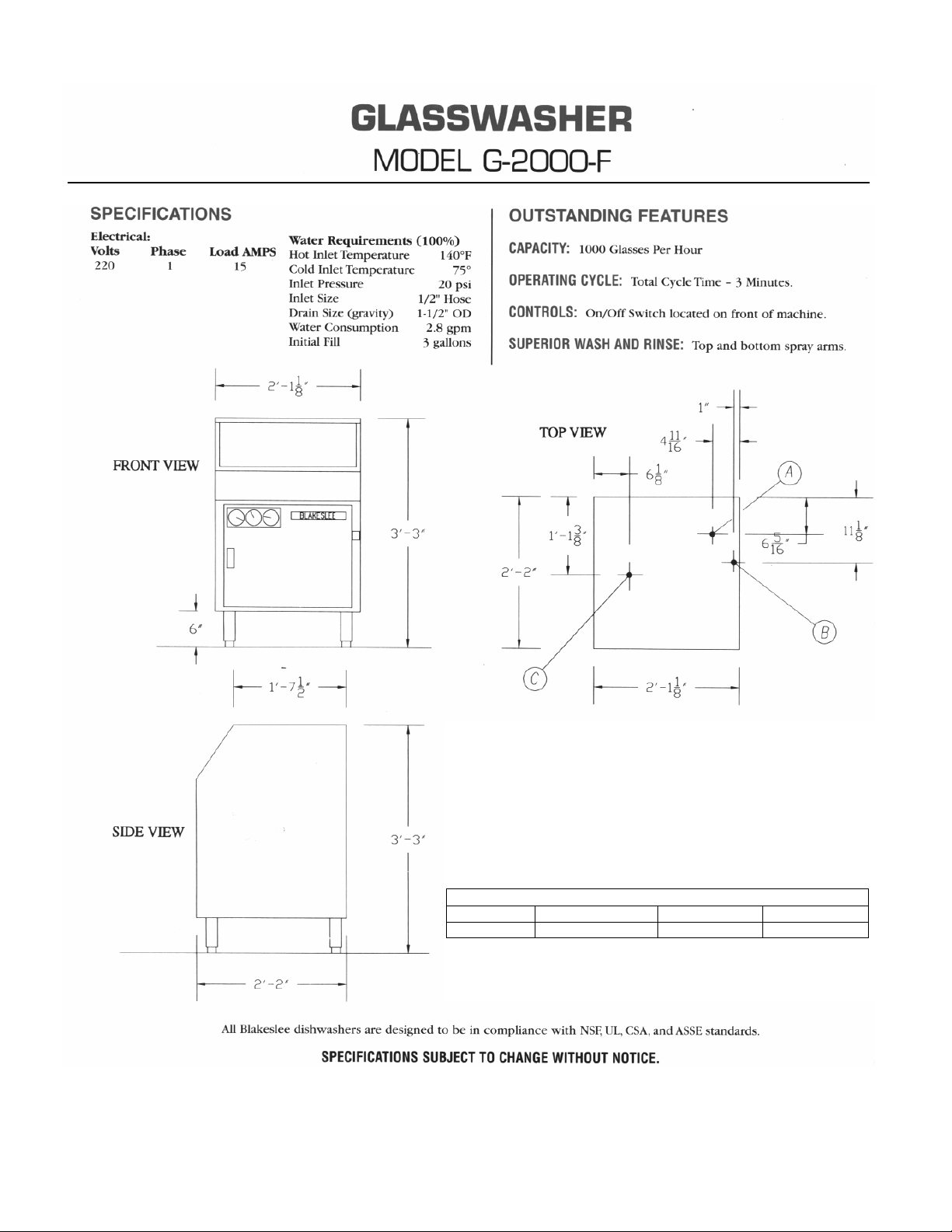
(A) HOT WATER CONNECTION (1/2” N.P.T. FEMALE FITTING)
(B) COLD WATER CONNECTION (1/2” N.P.T. FEMALE FITTING)
(C) 1-1/2” O.D. DRAIN
NOTE: If your water pressure is over 25 psi; installation of a
pressure reducing valve is necessary.
It is recommended that check valves be installed in both incoming
water supplies.
APPROXIMATE SHIPPING INFORMATION
MODEL DIMENSIONS WEIGHT CUBE
G-2000-F 47” xX27” X 28.5 160 lbs. 21.0 Ft.
1
Page 4

SECTION I OPERATION
1-1 Water
The wash tank is equipped with a float assembly that
turns water off when proper level is achieved.
The water temperature is controlled by a heater and a
thermostat. The thermostat should be set to provide a
wash water temperature between 145° F /60° C and
160° F /71° C.
1-2 Filling Wash Tank
Ensure that the standpipe is in place. Put the toggle
switch in the “AUTO” position. This will also turn the
heater on. To start the conveyor and detergent pump,
put the main switch on the front of the machine in the”
ON” position.
Detergent is fed from the supply container into the
detergent tank in controlled amounts by the detergent
pump. Use detergent at strength of 0.35% or as
recommended by your chemical supplier to
accomplish the necessary cleaning job.
NOTE: Use a heavy-duty NON-CHLORINATED liquid
detergent manufactured specifically for glassware
washing machines.
Your chemical representative will test the solution to
insure the proper strength is recommended.
NOTE: Many of the detergents used in glass and
dishwashers are harmful to the skin in their
concentrated form. To prevent accidental exposure to
this danger, be sure all hoses are secure and clamped
after service to machine.
1-3 Chemical Settings
Approximate chemical settings can be obtained by
counting the revolutions of the injector rotors.
For detergent, one revolution per second equals
approximately .035% concentration.
For sanitizer, one revolution in 5 seconds equals
approximately .035% concentration
For rinse agent, on revolution in 8 seconds is
suggested.
1-4 Detergent Injector Adjustment
1. Install the detergent tank standpipe and switch tank
fill toggle switch to “AUTO” position. The detergent
feeder will now feed detergent into the detergent tank
with water fill.
2
2. To increase detergent volume, turn the detergent
adjustment screw clockwise.
3. To decrease detergent volume, turn the detergent
adjustment screw counter-clockwise.
1-4 Sanitizer Injector Adjustment
The sanitizer is automatically fed into the line through
the sanitizer injector. Injection is into the final rinse
sprays.
1. When a new sanitizer container is installed, push
the prime button in and hold until sanitizer feed tubes
are full.
2. Start the washer—take a sample from the final rinse
spray tubes.
3. To increase sanitizer volume, turn the detergent
adjustment screw clockwise.
4. To decrease sanitizer volume, turn the detergent
adjustment screw counter-clockwise.
NOTE: If iodophor is being used as a sanitizer, it is not
necessary to use a separate rinse agent. To turn the
rinse agent injector “OFF” in this case, turn the
adjustment screw counter-clockwise until the rotor
stops turning.
NOTE: If chlorine is being used, a separate rinse
agent is required to prevent spotting.
1-5 Rinse Agent Injector Adjustment
1. When a new rinse agent container is installed, push
the prime button in and hold until sanitizer feed tubes
are full.
2. Start the washer—take a sample from the final rinse
spray tubes.
3. To increase rinse agent volume, turn the detergent
adjustment screw clockwise.
4. To decrease rinse agent volume, turn the detergent
adjustment screw counter-clockwise.
NOTE: The above only allows for testing the sanitizer
being fed. Actual sanitizing rinse solution should be
tested by your chemical supplier representative.
NOTE: To meet the requirement of N.S.F. standards,
iodophor in a concentration of 12.5 p.p.m. of chlorine
at 50 p.p.m. must be used in the final rinse.
Page 5

SECTION II DAILY CHECK-OUT
1. Clean machine. (See cleaning instructions on next page.)
2. Drain deflector is in position in drain.
3. Splash curtain is in position.
4. Right and left-hand trays are in position
5. Wash return screen for wash water is clean and in place.
6. Standpipe in the detergent tank is in place.
7. Bottom drain screen is in position.
8. Ensure that the mixing valve is adjusted.
9. Place the fill valve switch in “AUTO” position.
10. Wait for the detergent tank to reach the desired temperature.
(145° F /60° C and 160° F /71° C.)
11. Check the detergent, sanitizer, and rinse agent supply.
12. Switch the Glasswasher on.
3
Page 6

SECTION III CLEANING
Daily Cleaning Instructions:
1. Run glassware through the machine, and then clear the conveyor of glassware.
2. Turn the machine off.
3. Remove right and left-hand trays and splash curtain. Wash with hot soapy water, rinse thoroughly, and
then dry.
4. Remove the conveyor as follows:
• Remove sleeve in center of conveyor.
• Lift back of conveyor until it is free of drive gear.
• Raise front of conveyor and remove from wash section.
5. Remove drain deflector screens. Clean, wash and rinse areas with hot soapy water, rinse thoroughly,
then dry.
6. Replace drain deflector screens, conveyor, right and left-hand trays, and splash curtain. Ensure
conveyor is level and engaged with drive gear.
7. Turn auto fill switch to “OFF” position.
8. Remove wash return screen from below detergent tank. Clean and replace.
9. Turn fill switch to “AUTO” position.
10. Ensure there is product in the detergent, sanitizer, and rinse agent containers.
11. Check the detergent, sanitizer and rinse agent feed lines to ensure they are in place and securely
clamped.
4
Page 7
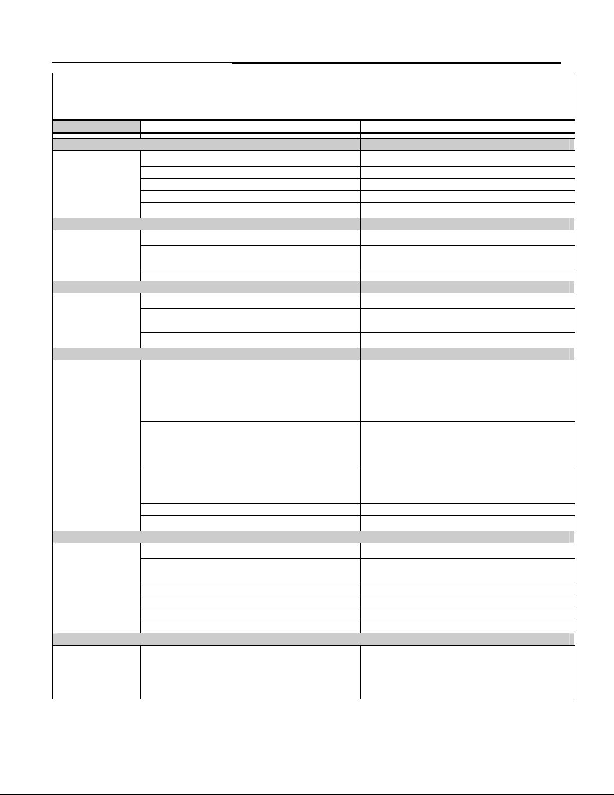
SECTION IV TROUBLE SHOOTING
Trouble shooting procedures are listed in the following table. Each trouble is followed by a list of possible causes
and suggested procedures to correct the cause.
In general, the procedures should be performed in the order in which they are listed.
Trouble Possible Cause Corrective Procedure
1. Conveyor does not turn
No power
Check the fuse on panel.
Drive motor burnt out Replace motor
Obstruction in wash or rinse section Remove the obstruction
Table limit switch not making contact or faulty Adjust micro-switch or replace if faulty
Conveyor not in position
2. Overspray from hood section
Splash curtain not in position
Washer running without any glasses on
Position properly
Reinstall splash curtain
Load conveyor with glasses
conveyor
Spray boxes plugged Clean thoroughly, use jet reamer provided
3. Chemical containers filling with water
Dirty rinse spray box
Element tube stretched; pinhole in tubing;
Refer to cleaning section
Replace tubing
loose hose ties
Worn flow washer in solenoid valve
4. Lack of pressure at wash spray tubes
No water in detergent tank
Replace flow washer
a. Make sure stand pipe is in place in tank
b. Check that the fill switch is in “AUTO”
position and that tank fills
c. Make sure that the float switch is operating
d. Check that the fill solenoid is operating
Pump not operating a. Check power supply to machine
b. Check pump capacitor, replace if
necessary
c. Replace pump if necessary
Pump defective a. Replace pump impeller if not working
correctly
b. Check for voltage drop
Wash spray box dirty Clean thoroughly, use jet reamer provided
Supply line plugged
5. Lack of pressure in spray boxes
Shut-off valve on supply line closed
Clear line of cause
Open valve
Low water pressure Have pressure taken on main cold water line
to machine. Pressure must be 25 p.s.i.
Rinse solenoid will not operate Replace coil if necessary
Rinse solenoid strainer plugged Clean or replace
Spray boxes plugged Clean thoroughly, use jet reamer provided
Supply line plugged
6. Continual flow of water through detergent tank or spray boxes with machine off
Solenoid valve not seating
Clear line of cause
a. Turn off water supply
b. Take apart and clean thoroughly
c. If above does not cure, replace plunger
and seat
5
Page 8

7. Hot water below required temperature in detergent tank
Thermostat set too low
Heater not on Check for power from switch to thermostat
Heater burned out Replace heater, Check float to insure heater
Thermostat defective Replace thermostat
Incoming water too cold Incoming water should be at 145° F /63° C
Rinse temperature should be a minimum of
8. Water on floor
Pump seal leaking
Rinse drain in wash chamber plugged Clear obstruction, clean machine
Wash drain in wash chamber plugged Clear obstruction, clean machine
Wash return screen in detergent tank plugged Clean screen
Drain screen under detergent tank plugged Clean screen
Main drain plugged
10. Sanitizer not feeding
No sanitizer in the container
Sanitizer crystallized or turned to gel, plugging
lines
Strainer at end of feed line in container
plugged
Sanitizer pump defective Replace pump
No sanitizer being fed Chemical adjustment set to low. Turn screw
Adjustment screw does not affect feed rate
11. Rinse agent not feeding
No rinse agent in the container
Rinse agent crystallized or turned to gel,
plugging lines
Strainer at end of feed line in container
plugged
Sanitizer pump defective Replace pump
No sanitizer being fed Chemical adjustment set to low/ Turn screw
Adjustment screw does not affect feed rate
6
Increase temperature by turning thermostat
clockwise
replace switch if necessary
is exposed when operating
minimum at supply for wash temperature.
Check supply
75° F. /24° C. To increase rinse temperature,
open mixing valve on inlet plumbing
Replace pump
Clean drain
Refill the container
Clean feed lines and sanitizer feeder, flush
with hot water. Use a fresh supply of
sanitizer
Remove feed line from container and clean
strainer
clockwise to increase rate of feed
Replace chemical injector control board
Refill the container
Clean feed lines and rinse agent feeder, flush
with hot water. Use a fresh supply of
sanitizer
Remove feed line from container and clean
strainer
clockwise to increase rate of feed
Replace chemical injector control board
Page 9

SECTION V PARTS
PROTECT YOUR EQUIPMENT
USE GENUINE BLAKESLEE PARTS
7
Page 10

MAIN ASSEMBLY
8
Page 11

ITEM
NO.
PART
NO.
1 76973 UPPER SPRAY BOX 2
2 77019 UPPER SPRAY BOX BRACKET 2
3 76962 LOWER SPRAY BOX 4
4 No Longer Used
5 76152 O-RING 1
6 75953 TRAY-R.H. 1
7 75954 TRAY-L.H. 1
8 75967 CENTER CO
9 76066 TURNTABLE WELDME
10 76000 ROLLER ASSEMBLY 4
11 76035 CURTAIN 1
12 76155 CURTAIN ROD 1
13 76156 DEFLECTOR SCREEN 2
14 76027 MAIN SWITCH 1
15 75937 LEG WELDMENT ASS’Y.-FRONT 1
16 75938 LEG WELDMENT ASS’Y.-REAR 1
17 75919 DOOR 1
18 76023 DOOR HA
* 76024 MAGNETIC CATH 1
19 76026 S/S SLIP HINGE 2
20 75944 SIDE PANEL-R.H. 1
21 75945 SIDE PANEL-L.H. 1
22 75940 TOP COVER 1
23 75964 VACUUM BREAKER ACCESS COVER 1
24 75939 BACK PANEL 1
25 75965 SWITCH MOUNTING BRACKET 1
26 75972 SWITCH ACTUATO
27 76467 MICRO SWIT
28 75973 STOP ARM 1
29 75982 WASTE BOX 1
30 75983 WASTE TRA
MAIN ASSEMBLY
DESCRIPTION
LUMN 1
NDLE 1
CH 1
Y 1
9
QTY
REQ
NT 1
R 1
Page 12

GAUGES, SENSORS AND DETERGENT PUMP
10
Page 13

GAUGES, SENSORS AND DETERGENT PUMP
ITEM
NO.
PART
NO.
DESCRIPTION
QTY
REQ
1 75920 GUAGE MOUNTING PLATE 1
2 70155 THERMOMETER 2
3 70156 PRESSURE GAUGE 1
4 18865 FLOAT SWITCH 1
5 76040 PROBE 1
6 75960 HEATING ELEMENT COVER 1
7 97990 HEATING ELEMENT COVER-TOP 1
8 75912 CONTROL BOX 1
9 75917 CONTROL BOX COVER 1
10 76037 TOGGLE SWITCH 1
11 07768 THERMOSTAT 1
12 76029 DETERGENT PUMP 1
NOT SHOWN
98849 TUBING 6
4” LENGTH
11
Page 14

ITEM
NO.
1 75986 DETERGENT TANK 1
2 75955 DRAIN TANK WELDMENT 1
3 76031 HEATING ELEMENT 1
4 76819 LOWER SCRAP TRAY 1
5 75960 HEATING ELEMENT COVER 1
6 75927 STAND PIPE 1
7 76822 UPPER SCRAP TRAY 1
8 75952 DETERGENT TANK FRONT COVER 1
9 75950 DETERGENT TANK REAR COVER 1
PART
NO.
DESCRIPTION
12
QTY
REQ
Page 15

WASH / RINSE FILL PLUMBING ARRAINGMENT
ITEM
NO
1 70286 3/8 Pipe To ½ Hose 2
2 76033 3/8 Solenoid 2
3 18528 ½ Pipe Plug 1
4 76055 3/8 Check Valve 1
5 76044 3/8 Male Tee 3
6 76041 3/8 X ½ Reducer Coupling 3
7 71312 3/8 Pipe Plug 1
8 76053 3/8 Line Strainer 2
9 70395 3/8 Close Nipple 2
10 76054 3/8 Ball Valve 1
11 70205 3/8 x 90 Elbow 1
PART
NO.
DESCRIPTION QTY
REQ
13
Page 16

CHEMICAL INJECTOR PLUMBING
ITEM
NO
PART
NO.
DESCRIPTION
QTY
REQ
1
1 76052 ½”-3/8” BELL REDUCER COUPLING 1
2 70395 3/8” CLOSE NIPPLE 1
3 76048 3/8” CROSS 1
4 76045 90° ELBOW 3/8” MALE to 1/4” TUBE 1
5 72631 BRASS MALE CONNECTOR 3/8” MALE to ¼” TUBE 1
6 72561 ¼” FLARED NUT 1
7 760006 MIXING ADAPTOR 1
8 76039 INJECTOR KIT 1
9 76049 90° ELBOW ¼” MALE PIPE to 3/8” HOSE BARB 1
10 76050 BRASS COUPLER ¼” MALE PIPE to ½” HOSE BARB 1
11 70201 3/8 ‘ VACUUM BREAKER 1
12 76041 ½”-3/8” BRASS REDUCER COUPLING 1
13 76046 3/8” MALE PIPE to ½” HOSE BARB 1
14
Page 17

5
7
WASH PUMP AND DRIVE
ITEM
NO
1 76030 WASH PUMP 1
2 75970 PUMP MOUNTING BRACKET 1
3 76049 90° ELBOW ¼” MALE PIPE TO 3/8” HOSE BARB 1
4 76032 DRIVE MOTOR 1
5 76927 DRIVE SPROCKET 1
6 76034 SPRING 1
7 77510 MOTOR COVER 1
PART
NO.
DESCRIPTION
15
QTY
REQ
Page 18

15
DETERGENT
PUMP
RINSE WASH
MAIN
POWER
WIRING DIAGRAM
16
Page 19

WIRING DIAGRAM PARTS LIST
SYM PART NO. DESCRIPTION QTY
DP 76029 Detergent Pump 1
TR 76537 Solid State Timer 1
FLO. 18865 Float Switch 1
PR 75292 Power Relay 1
M2 76030 Wash Pump 1
M1 76032 Drive Motor 1
SW 76467 Limit Switch 1
SOL 76033 Solenoid Valve 2
MSW 76027 Rocket Switch 1
SSW 20833 Toggle Switch 1
THS 07768 Thermostat 1
HE 76031 Heater 1
CAP 76038 Capacitor 1
RT 76913 Resistor 1
17
Page 20

CLEANING TOOL
PART
NO.
DESCRIPTION
QTY
REQ
76159 JET REAMER 1
18
Page 21

USA
Date of Installation
Serial
No.
Model
No.
Your new Blakeslee Glasswasher is warranted for one year from date of installation shown above
against defective materials and workmanship. If any defects are found within the warranty period;
parts, and labor involved with their replacement will be covered free of charge. Service must be
performed by a Blakeslee authorized service agency. All labor to be performed during regular working
hours. Overtime premium will be charged to the customer. All warranty parts are shipped by surface
transportation. If other means of transportation is requested the customer is required to pay the
premium. This warranty does not apply to damages resulting from errors in installation on the part of
other contractors, nor does it apply to machines which have been subject to accident, misuse, or
abuse. It is understood that Blakeslee’s warranty obligation with respect to machines located outside
of the United States or located in the state of Alaska is limited to the furnishing of replacement parts
only. In the state of Hawaii, repair labor is provided free of charge; travel time and expenses paid by
the customer. On the island of Oahu, repair labor, travel time and expenses are provided free of
charge. This is the entire and only warranty of Blakeslee. We neither assume nor authorize anyone
else to assume for us any other obligation or liability in connection with Blakeslee Machines.
Limited Warranty
● In no case can this warranty exceed eighteen (18) months from the date of shipment from our plant
at Chicago, Illinois
CANADA
Your new BLAKESLEE Glasswasher is warranted for one year from the date of installation shown
above* against defective materials and workmanship. If any defects are found within the warranty
period; parts, and labor involved with their replacement will be covered free of charge. Service must
be performed by a Blakeslee authorized service agency. All labor to be performed during regular
working hours. Overtime premium will be charged to the customer. Travel time and distance to
perform repairs over 100 Km. from the nearest authorized service agency will be charged to the
customer. All warranty parts are shipped by surface transportation. If other means of transportation is
requested the customer is required to pay the premium. This warranty does not apply to damages
resulting from errors in installation on the part of other contractors, nor does it apply to machines
which have been subject to accident, misuse, or abuse. This is the entire and only warranty of
Blakeslee. We neither assume nor authorize anyone else to assume for us any other obligation or
liability in connection with Blakeslee Machines. It is understood that BLAKESLEE’S guarantee
obligation with respect to machines located outside of Canada is limited to furnishing of replacement
parts only.
Date of Installation
Serial
No.
Model
No.
Limited Warranty
● In no case can this warranty exceed eighteen (18) months from the date of shipment from our plant
at Scarborough, Ontario.
 Loading...