


OWNER’S
MANUAL
BLAKESLEE 

 Division of Blako Inc.
FLIGHT – TYPE DISHWASHER
I.R.S.† INTEGRATED RECIRCULATING SYSTEM DESIGN
1844 South Laramie Avenue |
www.blakesleeinc.com |
1149 Bellamy Road North Unit 19 |
Chicago, IL 60804 |
|
Scarborough, Ontario Canada M1H1H7 |
Phone (708) 656-0660 |
service@blakesleeinc.com |
Phone (416) 751-2625 |
Fax (708) 656-0017 |
|
Fax (416) 751-8539 |
|
|
Revised 8/2005 |
NOTES

CONTENTS
|
INTRODUCTION . . . . . . . . . . . . . . . . . . . . . . . . . . . . . . . . . . . . . . . . . . . |
1 |
I |
DESCRIPTION . . . . . . . . . . . . . . . . . . . . . . . . . . . . . . . . . . . . . . . . . . . . |
2 |
II |
OPERATION . . . . . . . . . . . . . . . . . . . . . . . . . . . . . . . . . . . . . . . . . . . . . |
9 |
III |
CLEANING OF MACHINE. . . . . . . . . . . . . . . . . . . . . . . . . . . . . . . . . . . . . . . |
15 |
IV |
PREVENTATIVE MAINTENANCE AND MINOR REPAIR . . . . . . . . . . . . . . . . . . . . . . |
18 |
V |
USE OF ADDITIONAL EQUIPMENT . . . . . . . . . . . . . . . . . . . . . . . . . . . . . . . . . |
23 |
VI |
PARTS LIST. . . . . . . . . . . . . . . . . . . . . . . . . . . . . . . . . . . . . . . . . . . . . . |
43 |
Introduction
GENERAL.
The Blakeslee Flight Type dishwashing machine is available in many models. Each model is developed from one or more of the five basic modules (or tanks) shown in figure A. The P tank (24” long) which is the smallest is used only as a PRE-WASH tank and is always fitted to another tank as shown in figure B. The other four tanks are identified by their length. Any E, L, or M module can be a complete dishwasher in itself, or can be used as a pre-wash, wash or power-rinse tank in a multi-tank unit (see figure C). The Flight Type dishwasher is available in two widths; the standard width machine has a 20-inch conveyor; the extra wide model has a 30-inch conveyor.
EXPLANIATION OF MODEL DESIGNATION.
The Blakeslee Model designation indicates which tank, or tanks, are used to build a particular machine. A Model F-E
Dishwasher indicates that a single E tank (36” long) is the complete dishwasher. The Model F- EE Dishwasher consists of two E tanks, one of which is a wash tank and the other a power-rinse tank. When a pre-wash is desired, the P tank is added and the model becomes the F-PEE Dishwasher. If a larger capacity dishwasher is desired, a C, E, L, or M tank can be used as the pre-wash in a three tank machine. When adding the third tank to a F-EE machine, it becomes a Model F-EEE Dishwasher.
CONVEYOR DIRECTION.
When your order was placed, you specified the direction of conveyor travel. If the dishes enter the machine on the left, we refer to the machine as having L to R feed. Similarly, if the dishes enter on the right, the machine has R to L feed. The Illustrations included in this manual are of machines with L to R feed, unless otherwise noted.
|
|
|
|
|
|
|
|
|
|
|
|
|
|
|
|
|
|
|
|
|
|
|
|
|
|
|
|
|
|
|
|
|
|
|
|
|
|
|
|
|
|
|
|
|
|
|
|
|
|
|
|
|
|
|
|
|
|
|
|
|
|
|
|
|
|
|
|
|
|
|
|
|
|
|
|
|
|
|
|
FIGURE B. Dishwashing Machine with “P” Tank |
|
||
|
|
|
|
|
|
FIGURE A. Dishwashing Machine Modules |
|
|
|
||||
|
|
|
|
|
|
|
|
|
|
|
|
||
|
|
|
|
|
|
|
|
|
|
|
|
|
|
|
|
|
|
|
|
|
|
|
|
|
|
|
|
|
|
|
|
|
|
|
|
|
|
|
|
|
|
|
|
|
|
|
|
|
|
|
|
|
|
|
|
|
|
|
|
|
|
|
|
|
|
|
|
|
|
|
|
|
|
|
|
|
|
|
|
|
|
|
|
Model F-E F-L F-M
Model F-EE F-LL F-MM
Model F-EEE F-LLL F-MMM
FIGURE C. Dishwashing Machine Model Designations
1

2
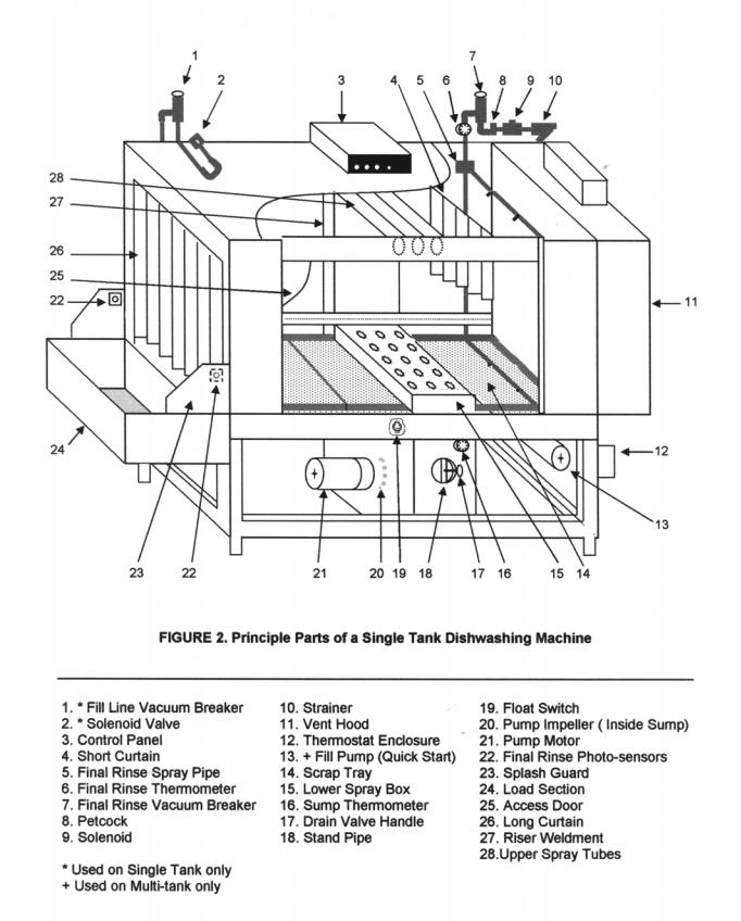
1-4. Single Tank Dishwashing Machine.
Figure 2 identifies the principle parts of a typical single tank dishwashing machine. The machine shown has Left to Right feed. The stainless steel tank is supported on a sturdy base and has adjustable legs. All interior parts are of stainless steel, or plastic construction to resist effects of present day detergents and cleaning chemicals. Curtains (26, figure 2) and a splash guard (23) at the entrance and exit prevent excessive splashing in the work room. A short curtain
(4) separates the washing and rinsing areas on models without power-rinse tanks. All curtains are easily removed for thorough cleaning. The large access door (25) lifts to allow quick cleaning and inspection of the dishwasher. The scrap trays (14) slide out easily through the access door area. The control panel (3) centralizes motor, pump, and heating unit controls. Electrically heated machines have a separate power connection for the heater elements.
1-5. Multi-Tank Dishwashing Machine.
Since Blakeslee dishwashing machines are developed from the module concept, the multi-tank machine includes all of the features outlined in the preceding paragraph for the single tank machine.
The primary advantages of a multi-tank dishwashing machine are the increased economy and capacity. The inclusion of a pre-wash tank increases economy by reusing overflow detergent wash water, thereby reducing detergent cost. Similarly, the power rinse is added to increase economy by pre-rinsing the dishes with water accumulated from the fresh water rinse, thereby reducing the amount of fresh final rinse water needed to cleanse the already pre-rinsed dishes. Capacity is increased by the addition of a full sized pre-wash or power rinse tank since conveyor speeds are then faster for multi tank dishwashers. (Note: capacities are determined by the National Sanitation Foundation.)
1-6. Wash Cycle.
Washing dishes requires two basic operations: first, the washing second, the rinsing. This paragraph describes the path of the wash water from the time it enters the machine through the complete wash cycle.
This unit has auto-matic tank fill & water level control. When the power switch is turned on, fresh water enters the dishwashing machine at the fill valve (2, figure 2) at the top of the machine. The water passes through the vacuum breaker (1) to internal piping. The vacuum breaker is a safety device designed to prevent contaminated water from the dishwashing machine being siphoned back into the fresh water supply lines if water supply pressure fails. The internal piping directs the water into the tank. When the tank is filled to the proper level, and deter-gent added, a float switch stops the fill, and turns on the tank heat. The tank heat is controlled by a thermostat (12).
The sump thermometer (16) indicates the wash water temperature. The wash cycle begins when the water is heated and the conveyor is manually started. The pump (20) directs the wash water through the riser weldment (27) at the rear of the machine. Upper spray tubes and a lower spray box are attached to the vertical riser. Nozzles on each spray tube, and spray box direct wash water at the dishes. Scrap trays (14) on either side of the lower spray box prevents dislodged food particles falling into the tank. The water return’s to the tank where it is ready to start the wash cycle again. A hollow standpipe (18) permits overflow water to flow down the drain. The standpipe permits overflow water to skim heavy soil, etc., that floats on top of the wash water, and carry it down the drain.
1-7. Final Rinse Cycle.
The final rinse water must always be fresh and hot (within a range of 180 F to 195 F). Hot rinse water enters the dishwashing machine at the strainer (10) and final rinse solenoid valve (9). The water travels through the vacuum breaker (7) and comes in contact with the final rinse thermometer (6). The thermometer indicates the temperature of the water entering the spray pipes (5). The spray pipes contain small nozzles sized and positioned for application of an even spray across the conveyor. Final rinse water is never allowed to run continuously. The final rinse photo-sensor (22) located on the entrance of the machine controls the solenoid (9) turning it on to coincide with the ware entering the final rinse.
1-8.Quick Start.
Quick Start utilizes the 180° water from the final rinse as an additional source to fill the tanks This system is designed to give you a much shorter start-up time by significantly decreasing the time necessary for the water to come up to temperature. See paragraph 2-1.
1-9.Conveyor Drive Mechanism.
The underslung links of the conveyor belt are supported by ½ inch stainless steel rods for standard and x-wide machines. Rollers located on the ends of the rods engage the drive sprockets attached to the shafts at each end of the dishwashing machine. Figure 3A shows the 48 tooth drive chain sprocket that is mounted in the head shaft in the conveyor drive section. The chain is driven by a ½ HP motor through a speed reducer.
A micro switch in the drive unit provides overload protection for the conveyor. If a conveyor jam occurs, the drive chain exerts a force on the lever arm, (see figure 3A). The lever arm moves to trip the micro switch open, causing the conveyor to stop. A spring is connected to the lever arm and spring tension is adjusted at the time of installation. Spring tension is set so that when a fully loaded conveyor jams, the micro switch opens.
3
4-
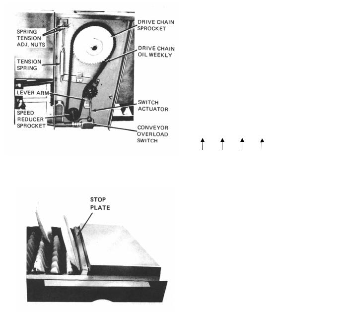
FIGURE 3A. Drive Assembly
FIGURE 3B. Conveyor Stop Plate
The tail shaft in the load section is supported in bearings which are mounted in take-up blocks. These blocks can be moved by turning take-up screws to remove slack from the conveyor belt. This adjustment is performed at time of installation and the take up screws are set in position with locking screws.
The stacking shelf on the conveyor drive section is a part of the conveyor stop mechanism. When clean ware or racks reach the discharge end of the conveyor the conveyor stops. The clean item presses a spring loaded stop plate. (See Figure 3B) this is the actuator for the micro switch.
As the stop plate moves under the stacking shelf, it trips the conveyor unload switch open and the conveyor stops. After the clean item is removed from the conveyor, the stop plate returns to its extended position and conveyor operation automatically resumes.
1-9. EXPLANATION OF CONTROLS.
1-10. Control Panel.
The control panel (figure 4) contains the motor switches, and indicator light. These controls are used as follows:
|
|
|
|
1 |
2 |
3 |
4 |
FIGURE 4. Control Panel
1.Power on/off switch
2.Pumps & Conveyor start switch
3.Pumps & Conveyor stop switch
4.Power on indicator light
a.All Blakeslee flight conveyor dishwashers are equipped with a door safety switch. The large inspection door must be closed and the switch lever extended to actuate the switch before any power can reach the control panel.
b.The power ON/OFF selector switch provides electrical power to the control panel. (1 figure 2)
c.The START and STOP pushbutton switches(2 and 3, Figure 2) are the panel controls for the conveyor and pumps electrical circuit. The START switch (2) is pressed to start the pumps and conveyor drive motors, and to provide electrical power to the final rinse limit switch and solenoid valve when needed. Pressing the STOP switch (3) disconnects power from the conveyor and pumps electrical circuit and stops the conveyor and pump motors.
d.Power light – Controlled by ON/OFF selector switch. Light is on when switch is on.
e.Automatic low water cut-off. This circuit connects the power supply to the pump and heat control circuits. If this circuit is not operational, the pumps and heating units will not operate. As the tank fills, the float ball moves up. When there is approximately 2-1/2 inches, of water in the tank the float switch (23 Figure 2) will close and this circuit becomes operational. The pumps can then be started and the tank heat will come on.
5
The tank heat pilot lamp will not light unless the Low Water Cut-Off circuit is operational. If the tank is emptied or if the tank water level falls below 2-1/2 inches, the float will come down, opening the switch and stopping the pumps and turning off the tank heat. In the multi-tank machine, there is a float in each tank except the P module pre-wash tank. If one tank empties, the pumps and heat will not operate for any of the tanks. Refilling the tanks will automatically reconnect the pump and heat circuits.
1-11. Auxiliary Conveyor Start/Stop Switches (OPTIONAL).
In addition to the conveyor controls on the control panel, auxiliary SRART/STOP pushbutton switches are factory installed at convenient customer selected locations. These auxiliary switches operate in the same manner as described in paragraph 1-10c. Operating personnel can start or stop the conveyor by pushing the appropriate button on the control panel or any of the auxiliary stations.
1-12. Conveyor Unload Micro Switch.
The conveyor unload micro switch is under the unload stacking shelf. This switch is tripped open when clean ware reaches the discharge end of the conveyor. When the switch is tripped, the conveyor stops. Removing the clean item from the conveyor automatically restarts the conveyor.
1-13. Conveyor Overload Micro Switch.
The conveyor overload micro switch is located in the drive unit. This switch is automatically actuated when the conveyor binds or is jammed. When this occurs, the conveyor stops. After the cause of the jam is determined and corrected, conveyor operation is resumed by pressing the conveyor START switch.
1-14. Final Rinse Photo-sensor and Solenoid
Valve.
The final rinse photo-sensor (22, Figure 2) When an object moving on the conveyor breaks the infrared beam between the sensors a signal is sent to the microprocessor starting the final rinse timer. The final rinse circuit is timed to activate the solenoid valve (9 Figure 2) as the first item enters the final rinse area and turn off the solenoid as the last item leaves the final rinse area. The microprocessor resets each time the infrared beam is broken allowing the machine to stay in operation until the final item is washed.
1-15. Drain Valve.
Each tank of the dishwashing machine is equipped with a drain valve (18, figure 2). The drain valve handle is turned clockwise ½ turn for the full closed position. This valve must be closed when the tank is filled and must remain closed while the dishwasher is operated. To empty the tank, the drain valve is turned counter-clockwise ½ turn to the open position. Each drain valve is equipped with a screen. The screen requires frequent cleaning, as outlined in paragraph 3-3.
1-16. Standpipe.
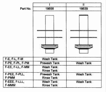
A hollow stainless steel drain standpipe (22, figure 1) fits into the drain valve seat in each tank. The standpipe is sealed by a rubber drain plug which fits over the standpipe and is secured by two stainless steel retaining rings. There are two standpipe styles; the configuration used in a particular tank is determined by the dishwashing machine model as shown in figure 5. The standpipe must be removed when cleaning the drain strainer. It is important that the correct standpipe is installed in each tank.
For tanks equipped with standpipe style I, the length of the standpipe determines the water level in the tank in which it is mounted. When the water reaches the top of the standpipe, it spills into the hollow standpipe and flows through to the drain. This also permits overflow water to skim heavy soil, etc, that floats on top of the wash water, and carry it down the drain.
On standpipe style II, the top of the standpipe is capped. These standpipes are used in wash tanks of machines which include a pre-wash tank. This capped standpipe prevents the excess water to drain. Instead, the excess water flows over the cut out portion of the baffle (in the tank common to both the wash and pre-wash tanks) into the pre-wash tank, as indicated in figure 5 A. The pre-wash tank is equipped with the style I standpipe.
6 |
FIGURE 5. Standpipes |
|
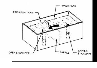
FIGURE 5 A.
Baffle between Wash and Pre-wash Tanks only
1-17. Heaters.
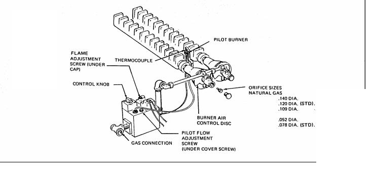
D. GAS. The gas heating system includes a gas control valve and a separate low water cut-off float switch. Gas enters the valve and is directed to the mixer heads on the burners. Two burners are arranged along the bottom rear of the tank. Burner orifice sizes are set at the factory and usually require no further adjustments; larger or smaller orifices for certain special gas B.T.U. outputs are available. Safety devices include a gas flue, safety pilot and built-in pressure regulator (natural gas only). Gas will not flow through the gas control valve unless the pilot light is lit, and there is water in the tank. Therefore, the operator must check periodically that the pilot light has not gone out, and relight it when necessary (refer to paragraph 2 – 6) The gas control is actuated by the control panel ON/OFF switch (1 figure 2) and is monitored with a thermostat. The HEAT indicator light
(6) will glow when the heat circuit is on, providing all tanks are filled with water.
1-18. Line Strainers.
A. ELECTRIC. The electric heating system is |
A. FINAL RINSE SYSTEM. The final rinse system |
||
includes a strainer (10, figure 1) to protect the solenoid |
|||
controlled by the ON/OFF switch (6, figure 2) and is |
valve (9, figure 1) from dirt. A good preventive |
||
monitored with a thermostat. This heating system |
maintenance program must include periodic cleaning of |
||
includes a contactor. The contactor is located toward |
the strainer screen (refer to paragraph 3-5). |
||
the rear of the machine on the right side (as viewed |
|
|
|
when facing the access door). Some machines are |
B. STEAM INJECTOR HEATING SYSTEM. This system |
||
equipped with optional common connection electric |
includes a solenoid valve protected with a strainer. |
||
heat junction box. A separate power supply, properly |
Periodic cleaning of the strainer is recommended (refer |
||
fused, must be connected to the contactor of each |
to paragraph 3-5). The strainer is located at the steam |
||
heated tank. |
inlet side of the solenoid valve. |
||
After the switch is turned ON, no other control of the |
C. STEAM COIL HEATING SYSTEM. This system |
||
system is required by the operator. The HEAT |
includes a solenoid valve protected with a strainer. |
||
indicator light (6) will glow when the heat circuit is on, |
Periodic cleaning of the strainer is recommended (refer |
||
providing all tanks are filled with water. |
to paragraph 3-5). The strainer is located at the steam |
||
B. STEAM INJECTOR. This heating system is |
inlet side of the solenoid valve. |
||
1-19. Venting and End Hoods. |
|||
automatically controlled with a thermostat and |
|||
solenoid valve. Steam enters a strainer, passes |
The end hoods are attached to the inlet and exit of the |
||
through the solenoid valve and a check valve and |
|||
enters the steam water heaters in the tank. The |
dishwashing machine to reduce water splash and |
||
solenoid valve is actuated by the control panel |
exhaust the steam from the dishwashing machine area. |
||
ON/OFF switch (1, figure 4) and is monitored with a |
Exhausting the steam reduces the humidity in the |
||
thermostat. After the switch is turned ON, no other |
dishwashing department which contributes to more |
||
control of the system is required by the operator. The |
efficient working conditions and quick self-drying of |
||
HEAT indicator light (6) will glow when the heat circuit |
dishes. |
Each hood must be connected to a ventilating |
|
is on. |
duct; vent opening on the hood is 4 x 16 inches. |
||
|
|
||
C. STEAM COIL. The steam coil heating system is |
Figure 1 shows the standard full-length unload end hood |
||
with 10 inch wide side panels and standard load-end |
|||
automatically controlled with a thermostat and |
hood. |
Extended full-length load and unload end hoods |
|
solenoid valve. Steam enters a strainer, passes |
with up to 16-inch wide side panels are available as an |
||
through the solenoid valve and enters the steam coil in |
option. |
Extended hoods provide more space for steam |
|
the tank where heat transfers to the tank water. A |
collection and additional splash protection. |
||
steam trap at the coil exit connects to the condensate |
A damper in the hood is adjustable to control the |
||
drain. The solenoid valve is actuated by the control |
exhaust volume. To adjust the damper, place a wrench |
||
panel ON/OFF switch (1, figure 2) and is monitored |
on the flat of the damper rod and loosen the stop nut on |
||
with a thermostat. After the switch is turned ON no |
the side of the hood and turn the damper rod; tighten the |
||
other control of the system is required by the operator. |
stop nut to lock the damper in position while holding rod |
||
|
|||
in position with wrench.
7
The best damper position will vary according to the size of the dishwashing room and machine. Allow majority of steam to escape without loss of water temperature in tanks. NOTE: if damper is open too much heat will be lost from the tank.
CAUTION: Do not vent into wall or ceiling or concealed space of a building.
1-20. Splash Guards.
Figure 1 shows splash guards attached to either the end hoods or the end of the tank. These splash guards are designed to divert water that is not contained by the end hoods back into the load and unload tanks.
1-21. GAUGES
1-22. Sump Thermometer.
Each tank of the dishwashing machine is equipped with a sump thermometer (19, figure 1). This thermometer indicates the temperature of the water in the tank. NSF requirements for water temperatures are indicated in the table at the end of this section. After the dishwashing machine is filled with water and the heating unit is turned on, the sump thermometer should be observed periodically to assure that the proper temperatures are being maintained.
1-23. Final Rinse Thermometer.
The final rinse thermometer (6, figure 1) is located above the last tank of the dishwashing machine. This thermometer indicates the temperature of the final rinse water entering the machine. An NSF requirement for final rinse water is 180 F – 195 F. Heating the final rinse to 180 F is generally accomplished with a booster heater. This heater was either purchased with the dishwashing machine, or was part of the regular kitchen equipment.
The heat from the final rinse water assures sanitation and assists in heating the ware for rapid drying. During dishwashing operation, the final rinse thermometer should be observed periodically to assure that proper temperature is being maintained.
1-24. Water Temperature Chart. |
|
|
|
TYPE OF |
OPERATION |
NSF MINIMUM |
|
MACHINE |
|
TEMPERATURE |
|
SINGLE |
Wash |
160 F |
|
TANK |
Final Rinse |
180 |
F - 195 F |
SINGLE |
Prewash |
110 F - 140 F |
|
TANK |
Wash |
160 F |
|
W/PREWASH |
Final Rinse |
180 F - 195 F |
|
|
Wash |
150 F |
|
2 TANK |
Power Rinse |
160 F |
|
|
Final Rinse |
180 |
F – 195 F |
|
Prewash |
110 F – 140 F |
|
2 TANK |
Wash |
150 F |
|
W/PREWASH |
Power Rinse |
160 F |
|
|
Final Rinse |
180 |
F |
|
Prewash |
110 F – 140 F |
|
3 TANK |
Wash |
150 F |
|
|
Power Rinse |
160 |
F |
|
Final Rinse |
180 |
F – 195 F |
1-25. Final Rinse Pressure Gauge. (OPTIONAL)
Properly heated final rinse water under pressure between 15 to 25 psi (flow pressure) will effectively rinse away detergent. The optional gauge is used to monitor this flow pressure. Flow pressure is the indicated water pressure with all final rinse valves open and the final rinse in operation.
1-25-A. Final Rinse Pressure Gauge Petcock.
The final rinse system is equipped with a ¼- inch N.P.T. petcock (8, figure 1). This device is used in conjunction with detergent reps. & health inspectors test equipment. Be sure petcock is closed (valve lever horizontal) before removing plug to install equipment.
8
Section II. Operation
FIGURE 6. Flight Type Conveyor Link
Two types of racks are recommended: the multipurpose rack and the combination rack. There are more holes in the bottom of the combination rack than in the multi-purpose rack. The multi-purpose rack is used for washing plates, saucers, trays (14 x 18 inch maximum) and any ware except silverware. The combination rack is used for washing silverware and small ware such as cups, bowls and glasses.
|
|
|
|
|
|
|
|
|
|
MULTI-PURPOSE RACK |
COMBINATION RACK |
|
|
||
|
|
PART NO. W-0-16428 |
PART NO. W-0-16429 |
FIGURE 7. Proper Loading of Racks
2-1. PREPARING MACHINE FOR OPERATION.
Perform the following steps to insure proper dishwasher operation.
1.Check that clean scrap trays are in position on either side of lower spray boxes. Be sure the curtains are in position at dishwasher entrance, between the wash and rinse areas of tanks, and at dishwasher exit.
2.Close tank drain valves and access doors.
3.Put correct amount of detergent in detergent dispenser box. Observe the recommendations of the detergent manufacture.
4.Be sure the door safety switch is pulled out so the inspection door cannot be opened.
5.Turn the ON/OFF switch in the control panel (1, figure 2) on. The dishwashing machine will begin filling. The fill indicator light should come on. Multi tank machines fill using the rinse tank fill and the final rinse. Water is pumped from the rinse tank to fill the wash tank. See Quick Start paragraph 1-8. Quick start is optional on single tank machines.
6.The machine will automatically stop filling when the water reaches its proper level. At this point the heat indicator light should come on.
7.Observe sump thermometers; minimum operating temperatures are indicated on the thermometers, and in the table at the end of section I.
8.Press the start switch on the control panel.
The dishwasher is now ready for loading.
2-2. LOADING MACHINE.
2-3. Conveyor Links.
The underslung conveyor links are suspended between Stainless steel cross rods to form a flat belt surface for easy loading and unloading. The double link shown in figure 6 accommodates all regular and extra-heavy ware that does not require racks. Platter and tray sizes up to 14 x 18 inches maximum can be placed directly in the links. Some dishwashing machines, equipped with pre-flushers and used primarily for washing trays, are equipped with a single link conveyor belt. The slightly wider spacing of the single link is especially suitable for trays, but does accommodate other ware as well.
When loading the conveyor links, observe the following: Place dishes in links with the soiled surface tilted up. Place oblong items, such as platters and trays, with the long side in the link. For example, to wash a 14 x 18 inch tray, place the tray with the 18 inch side in the link.
2-4. OPERATING THE DISHWASHER.
Observe the following instructions to obtain maximum performance from the dishwashing machine. Also refer to paragraph 2-7 for helpful suggestions.
1.Whenever possible, instruct bus boys or wait staff to stack the soiled dishes according to sizes as they are brought to the soiled dish table.
2.Remove by hand, rubber scraper, or pre-washing as much food particles left on the dishes as possible. This will reduce pollution of water, insure the cleanest possible wash water and lower detergent costs.
9
3.Load the conveyor links and racks as described in paragraphs 2-3 and 2-4. Slide the racks of soiled ware onto the conveyor. Continue loading the machine with soiled ware as fast as the conveyor allows.
4.Clean ware must be removed from the unload section continuously. When ware is not removed from the conveyor, the conveyor micro switch is tripped causing the conveyor to stop.
5.Scrape and rack more dishes and “feed” the racks of soiled ware to the machine as fast as it will take them
2-5. STOPPING MACHINE AFTER OPERATION.
To stop the dishwasher, observe the following.
1.Press the STOP button.
2.Turn ON/OFF switch to the OFF position.
3.Open drain valve.
4.Clean machine (paragraph 3-1)
2-6 GAS PILOT LIGHTING INSTRUCTIONS.
The pilot burner is accessible from the right side of the machine. Figure 8 shows the gas heat unit and
6.Continually check wash and rinse temperatures. identifies the pilot burner and pilot lighting button.
NOTE: For machines equipped with gas heating units, a decreasing temperature may be caused by the pilot light going out. Check that the pilot light is lit; when necessary; relight as outlined in paragraph 2-6.
7.Be sure enough detergent is being added to the wash water to keep it at an effective strength if an automatic dispenser is not being used.
8.Repeat steps 2 through 8 until all dishes have been washed.
10. Stop dishwasher (paragraph 2-5) and perform the daily cleaning (paragraph 3-1).
Use a fireplace match, or a long piece of rolled – up paper, to light the pilot burner as follows;
1.Slightly depress control knob if at PILOT position and turn clockwise to OFF. Wait 5 minutes for all unburned gas to vent. REMEMBER that LP gas does not vent upward naturally.
2.Turn the control knob to PILOT, depress it completely, and light the pilot burner. The knob must be held down about one minute before the pilot burner will stay lit after releasing the knob.
3.Turn the knob to ON. Gas burners should ignite. If not, repeat above sequence.
FIGURE: 8. Gas Heat Unit
10
2-.7 HELPFUL HINTS
2-8. Proper Use of Flight Type Dishwashing
Machine.
The Flight Type dishwashing machine provides a direct load, single-handling method of cleaning dishes. Since this is a random load system, all sorting and stacking can be eliminated before loading. The machine operators or waitresses simply remove the soiled dishes from the container (tote box, tray, etc.) used to bring the soiled ware into the dish room, scrape soil into appropriate containers, and load the item in the conveyor link or rack. Cups, glasses and miscellaneous items like creamers, butter dishes, etc. are placed in suitable racks. When a rack is full, it is placed on the conveyor at random. Silverware is placed in a soak sink. When a rack full of silverware is accumulated, it is placed at random on the conveyor belt. Sorting and stacking is done at the unload end. Clean ware can be stacked on storage shelves or on portable carts for the transportation to other areas in the dish room.
To obtain full advantage of the direct-load system, the following equipment should be provided at the load end of the machine: a suitable soil container (scrapping trough, disposer, etc.); silver soak sink; and shelves (or some convenient method) for loading racks and for storing empty racks. For peak periods of operation, shelves for temporary storage of entire tote boxes or trays full of soiled ware are also convenient on the load end of the machine.
2-9. Loading Precautions.
The dishwashing machine is built for washing dishes and other tableware only, not for pots, pans or other kitchen equipment. Any item that cannot be placed “in” the conveyor link or dish racks without falling over should not be cleaned in this machine.
Load racks properly. Glasses, cups and creamers should be placed face down in the racks.
Care must be used not to overfill a silver rack. The bottom of the rack must be visible in several areas through the silver ware. If not, the rack is overfilled and poor results will be obtained.
Small ware (saucers, dessert dishes etc.) that are placed directly in the conveyor belt will not actuate the conveyor stop mechanism. All small ware must be placed in racks in order to trip the stop mechanism.
2-10. Dish Handling Techniques – Flight Machine with regular Load Section
LOADING OPERATIONS. The Flight Type machine is designed for the direct-load, single chandelling system of cleaning dishes: whenever possible, use the machine as described in paragraph 2-8. When the size or layout of the dish room limits activity at the load section, it may be necessary to perform the scraping or rack loading operations at a separate location. When rack loading is performed away from the load section, consider establishing a soiled dish table. Instruct your busboys or wait staff to arrange the soiled ware on the
dish table in an orderly manner as the ware is brought to the table. There should be designated places for depositing scraps, napkins, and soiled ware. In many instances, cups, glasses, butter dishes, etc., can be placed directly in the appropriate rack by the bus boys or wait staff. Mobile equipment can be helpful to convey the soiled ware to the dishwashing machine.
SCRAPING DISHES. Do a good job of removing left over food from the dishes. Scrape dishes by hand, with a rubber scraper, or by pre-washing before placing them in the conveyor links or racks. Doing this job properly helps to maintain cleaner wash water.
2-11. Dish Handling Techniques – Flight Machine with Extended Load Section
LOADING OPERATIONS. The extended load machine is best used as described in paragraph 2-8. The extended load section provides ample space for performing all of the loading operations and accommodates three or more personnel at the same time. The extended load machine is usually purchased with optional equipment or arranged with existing equipment, such as scraping trough, rack loading and storage shelves, and a pre-flushing system. For proper and efficient use of Blakeslee option items refer to section V.
SCRAPING DISHES. Heavy soil must be removed from the dishes before loading them into the links or racks; a minimum of pre-scraping is required. A machine equipped with a pre-flusher requires practically no pre-scraping.
2-12 Detergents.
Detergents should be used according to the detergent manufacturer’s recommendations. Their representative knows the capabilities of their detergents and can determine the proper treatment of your water for proper use with their product. The wash water must be kept at an effective strength to obtain good washing results. Use a good detergent. Never use a foaming soap or soap flakes. Ask your local detergent man for his help and heed his advice.
2-13. BRIEF DESCRIPTION OF SEQUENCE OF OPERATION.
The sequence of operation for various dishwasher models is described in paragraph 2-14 through 2-16 and represented in figures 9 through 13. Many of the parts referred to in these descriptions are shown in figure 1 of this manual.
2-14 Single Tank Dishwashing Machine. (See Fig. 9)
WASH CYCLE. The pump directs the wash water through the riser weldment at the rear of the machine to upper spray arms and to a lower spray box. Nozzles on the spray arms, and spray box direct the wash water at the dishes.
11
Trays on either side of the lower spray box prevent dislodged food particles falling into the tank. The water returns to the tank, where it is ready to start the wash cycle again. The hollow standpipe permits overflow water to flow down the drain and acts as a surface skimmer.
FINAL RINSE CYCLE. Hot final rinse water enters the machine at the strainers and solenoid valve. The water travels through the vacuum breaker and enters the spray pipes. Nozzles on the spray pipes direct the rinse water at the dishes.
FIGURE 9. Single Tank Water Distribution Diagram
2-15. Single tank with P-Module Pre-Wash (See Fig.11).
PRE-WASH CYCLE. The pre-wash tank is filled with overflow water from the wash tank. The pre-wash water is pumped through the riser weldment at the rear of the machine where it enters an upper spray arm. (a lower spray arm is available as optional equipment) Nozzles on the spray arm direct the pre-wash water at the dishes. A scrap tray below the conveyor track prevents dislodged food particles falling into the tank. The water returns to the tank, where it is ready to start the pre-wash cycle again. The hollow standpipe permits overflow water to flow down the drain.
WASH CYCLE. The pump directs the wash water through the vertical riser at the rear of the machine to upper spray pipes, and to a lower spray box. Nozzles on the spray arms and spray box direct the wash water at the dishes. Scrap trays on either side of the lower spray box prevent dislodged food particles falling into the tank. The water returns to the tank, where it is ready to start the wash cycle again. The capped standpipe prevents the overflow water flowing down the drain. Instead, the water is forced to overflow into the pre-wash tank.
FINAL RINSE CYCLE. The final rinse cycle for this machine is identical to the final rinse cycle described in paragraph 2-12.
FIGURE10. Single Tank with P- Module Pre-Wash Water Distribution Diagram
12
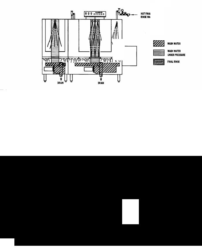
2-16. Two Tank Dishwashing Machine (See Fig. 11).
WASH CYCLE. The pump directs the wash water through the riser pipe at the rear of the machine to upper spray pipes and to a lower spray box. Nozzles on each spray arm and spray box direct the wash water at the dishes. Scrap trays on either side of the lower spray box prevent dislodged food particles falling into the tank. The water returns to the tank, where it is ready to start the wash cycle again. The hollow standpipe permits overflow water to flow down the drain.
POWER RINSE CYCLE. The pump directs the rinse water through the riser weldment at the rear of the machine to upper spray arms and a lower spray box.
Nozzles on each spray arm and spray box direct the rinse water at the dishes. Scrap trays on either side of the lower spray box prevent dislodged food particles falling into the tank. The water returns to the tank, where it is ready to start the rinse again. The hollow standpipe permits overflow water to flow down the drain. The rinse water is replenished with used final rinse water.
FINAL RINSE CYCLE. Hot final rinse water enters the machine at the strainer and solenoid valve. The water travels through the vacuum breaker and enters the spray pipes. Nozzles on the spray pipes direct the rinse water at the dishes. The used final rinse water falls into the power rinse tank.
FIGURE 11. Two Tank Water Distribution Diagram
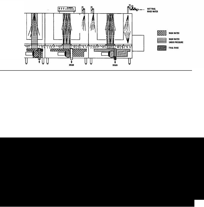
2-17. Two Tank with P-Module Pre-Wash (See Fig.12).
PRE-WASH CYCLE. The pre-wash cycle for this machine is identical to the pre-wash cycle described in paragraph 2-13.
WASH CYCLE. The pump directs the wash water through the riser weldment at the rear of the machine to upper spray arms and a lower spray box. Nozzles on each spray arm and spray box direct the wash water at the dishes. Scrap trays on either side of the lower spray box prevent food particles falling into the tank. The water returns to the
tank, where it is ready to start the wash cycle again. The capped standpipe prevents the overflow water flowing down the drain. Instead, the water is forced to overflow into the pre-wash tank.
POWER RINSE CYCLE. The power rinse cycle for this machine is identical to the power rinse cycle described in paragraph 2-14.
FINAL RINSE CYCLE. The final rinse cycle for this machine is identical to the final rinse cycle described in paragraph 2-14.
FIGURE 12. Two Tank with P – Module Pre-wash Water Distribution Diagram
13
 Loading...