


OWNER'S MANUAL
D-8/DD-8
HIGH TEMP
DISHWASHER
BLAKESLEE |
BLAKESLEE |
1844 South Laramie Avenue |
66 Crockford Boulevard |
Chicago, IL 60804 |
Scarborough Ontario, Canada M1R 3C3 |
Phone: (708) 656-0660 |
Phone: (416) 751-2625 |
Listed below are items NOT covered under warranty.
1. Lighting of Gas Pilots.
At the time of installation the gas pilots and burners should be adjusted. Continued failures of pilot lights would indicate dirty gas lines, improper original adjustment or intermittent drafts blowing out the flame.
2. Replacing Fuses or Resetting Overloads.
Replacing a blown fuse or resetting an open overload breaker is a very simple procedure and is the owner's responsibility. If the machine continues to blow fuses or open the overload breaker, contact you nearest authorized Blakeslee Service Center.
3. Adjusting Tank Heats.
Heat adjustments are covered in this Manual and must be adjusted depending upon desired results.
4. Proper Loading of Dishes.
It is important the machine owner's personnel observe the instructions outlined in paragraph 2-2.
5. Cleaning Drain Valves.
Foreign articles lodged in the drain valve seat should be removed as a part of normal daily cleaning.
6. Cleaning Rinse or Wash Nozzles and Line Strainers.
Keeping a dishwasher clean and removing obstructions from the nozzles and line strainers will be a periodic function of the machine owner's personnel. The cleaning periods will vary depending upon impurities in the water supply and cleanliness of the washing operation.
7. Final Rinse Water. (High Temperature Dishwashers Only)
Most frequent of all complaints in any dishwashing machine is that of poor final rinse. It is the responsibility of the owner to provide 180°to195° (plus) water at 15-25 Ib. flow pressure through clean unobstructed water lines. If the machine has a factory equipped final rinse water booster, the owner must supply the booster with a minimum of 140° temperature water.
8. Electric Boosters and Garbage Disposals.
Although these units may have been purchased with the machine, they are warranted by the individual manufacturer. Consult the nearest factory authorized representative for these particular items.
9. Overtime Charges.
All warranty work is performed during normal daytime working hours (8 AM — 4:30 PM Monday through Friday). If warranty is requested at other times, the owner will be required to pay the overtime premium for all labor charges.
10. Chemical Dispenser. (Low Temperature Dishwashers Only)
Replacement and lubrication of the blue hose used in the chlorine dispenser pump is a simple procedure and the owner's responsibility. Refer to Owners Manual for further instructions.
Blakeslee
Service Department
TABLE OF CONTENTS
SECTION 1 |
DESCRIPTION |
|
1-1 |
General Description |
1 |
SECTION 2 |
INSTALLATION |
|
2-1 |
Plumbing and Electrical Connections |
3 |
2-2 |
Location |
3 |
2-3 |
Dish Table |
3 |
2-4 |
Electrical Connections |
3 |
2-5 |
Pump Rotation |
3 |
2-6 |
Fill Rinse |
4 |
2-7 |
Drains |
5 |
2-8 |
Heating Systems |
5 |
2-9 |
Electric Heater |
5 |
2-10 |
Gas Heater |
5 |
2-11 |
Steam Injection Heater |
9 |
2-12 |
Steam Coil Heater |
9 |
2-13 |
Electrical Detergent & Rinse Injector Connections |
9 |
SECTION 3 |
OPERATION |
|
3-1 |
Preparing Dishwasher for Operation |
11 |
3-2 |
Auto Tank Fill |
11 |
3-3 |
Timed Tank Fill |
12 |
3-3A |
Tank Selection (DD-8 only) |
12 |
3-4 |
Soiled Dish Table Operation |
12 |
3-5. |
Loading Machines |
13 |
3-6 |
Operating the Dishwasher |
13 |
3-7 |
Shut down and Cleaning |
14 |
SECTION 4 MAINTENANCE AND LUBRICATION |
|
|
4-1 |
Motor |
15 |
4-2 |
Pump |
15 |
4-3 |
Doors |
15 |
4-4 |
Wash Arms |
15 |
4-5 |
Final Rinse Arm and Nozzles |
15 |
4-6 |
Pump Motor Overload Protection |
15 |
4-7 |
Troubleshooting |
15 |
SECTION 5 |
OPTIONAL EQUIPMENT |
|
5-1 |
General |
19 |
5-2 |
Hot Water Boosters |
19 |
5-17 |
Machine Mounted Booster |
23 |
5-20 |
Automatic Tank Fill |
24 |
5-21 |
Timed Fill |
24 |
5-22 |
Door Safety Lock |
24 |
5-23 |
Tank Selection (DD8 only) |
24 |
SECTION 6 ILLUSTRATED PARTS LIST |
|
|
See Separate Table of Contents List |
25 |
|
1-1. GENERAL DESCRIPTION
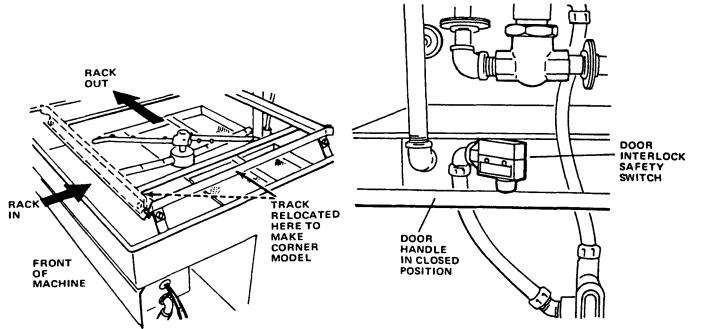
The machine door is counterbalanced and opens to provide easy access to the inside of the machine.
The machine can be easily changed from a straight thru to corner model by the simple movement of one track rail. (See Figure 1-1).
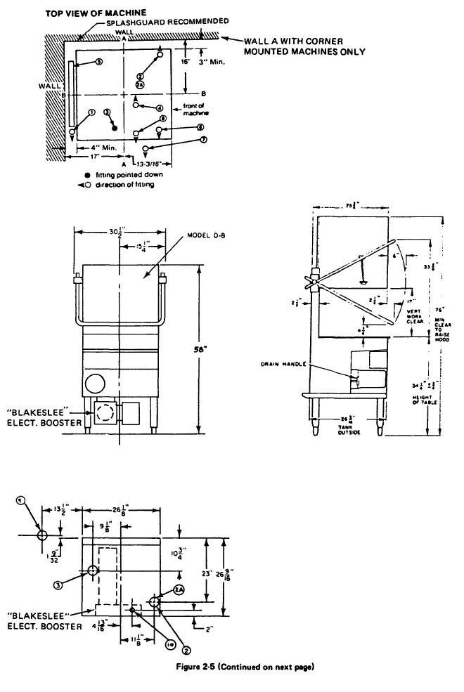
If your machine is a single D8, and is to be used in a corner, the right side must always be positioned against one wall (see Figure 2-5). DD8 machines, if used in a corner, should have been ordered so that the operating controls are placed in the control box of the tank that is farthest from the corner. (Left tank or right tank.)
1-2. DOOR SAFETY SWITCH
All machines are equipped with a door safety switch. (See Figure1- 2). The machine will not operate when door is open. If the door is accidentally opened during an automatic cycle, the machine operation will stop. (Some models may be equipped with Optional Door Safety Lock. See para. 5-22 for description of lock.) When the door is closed, the operator must press the start button again to finish the wash cycle. If the door was opened when the machine was in the rinse cycle, the machine will automatically finish the rinse cycle when the door is closed again.
Figure 1-1. Relocating Track to Convert Straight-thru to Corner Model.
SECTION 1 DESCRIPTION
1-3. MOTOR
Machine is equipped with a 1 HP 1725 RPM motor. D8's have one, DD8's have 2.
1-4. CONTROL CIRCUIT
All machines are supplied with a 115 volt, A.C. control circuit.
1.5. VACUUM BREAKER
The fill line has a vacuum breaker installed in it to prevent any back flow of water into the fresh water supply line. If a negative pressure develops in the supply line, the loss of pressure permits a check valve inside the breaker to drop, sealing the orifice while at the same time a vent opens admitting air to the system to break the vacuum.
1-6. HEATERS
Wash tank water is heated by electricity, steam coil, steam injection, or gas. Electrically heated machines are available in 208, 240, 440, or 480 volts only.
Figure 1-2. Door Safety Switch
1
1.7. AUTOMATIC OR TIMED TANK FILLED (Optional)
All machines can be supplied with an automatic or timed tank fill. (See para. 5-20 & 5-21 for description).
1-8. Final Rinse Boosters (Optional)
Machine can be equipped with an optional built-in electric booster, remote mounted electric booster, or remote mounted steam booster. These boosters are designed to raise rinse water temperature from 140° F to 180-195°. (Refer to para. 5-2 for description).
1-9. Heat and Voltage Field Changeover
One of the most desirable features of the D8 Dishwasher is it can easily be field converted to different tank heats and voltage. All of the tank heats fit on the same mounting bracket. All that is necessary to convert from one type of heat to another is to order the kit for the type of heat desired and make the wiring changes as described below, in the parts list pages of this manual and the wiring diagram, W-3- 17715. figure 15F-20 of Modular Dishwasher Service Manual. (NOTE: to keep the cost of conversion as low as possible, it will be necessary to purchase a few electrical components such as flexible waterproof conduit, wire, etc. locally).
Following are the complete assemblies needed for tank heat conversion.
Natural Gas |
W-0-17966 |
L.P. Gas |
W-0-17967 |
Steam Injector |
W-3-12988 |
Steam Coil |
W-3-13129 |
Electric |
W-0-95377 |
NOTE: Electric heat not available for 115 volt machines.
Additional conversion installation note.
When changing either to or from single to three phase electrical power, the wash pump motor must be changed. The motor protection fuses must also be changed. See parts description in figure 6-11and wiring diagram, figure 15F-20 of Modular Dishwasher Service Manual.
When changing from 115 volts to 208, 230, 440, or 480 volts, single or 3 phase, a transformer must be added. The motor protection fuses must also be changed (see parts description in figure 6-11 and wiring diagram, figure 15F-20 of Modular Dishwasher Service Manual.
2
2-1. PLUMBING & ELECTRICAL CONNECTIONS
Various plumbing connections are tagged "180° water," "steam," "gas," etc.
NOTE: Installation must be made by qualified workmen observing all applicable Sanitary, Safety & Electrical Codes.
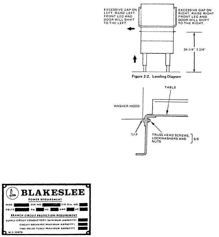
2-2. LOCATION
Place dishwasher in its proper location. (See figure 2-5 or 2-6). Maintain 34-1/4" ±3/4" height. (See figure 2-2). Level dishwasher by turning adjustable feet. INITIAL SETTING OF DISHWASHER MUST
BE LEVEL TO PERMIT HOOD TO OPEN AND CLOSE PROPERLY. If one side of the door has an excessive gap after the dishwasher is leveled, adjusting one of the front legs up or down will remedy this. (See figure 2-3). Do not make any service connections until machine is set and leveled and doors open and close properly.
2-3. DISH TABLE
Dish table should be lipped into the dishwasher. (See figure 2-4). Use silicone type sealer between dish tables and dishwasher. Secure with stainless steel (S/S) truss head screws.
2-4. ELECTRICAL CONNECTIONS
Check machine data plate before making any electrical connections. Connections must agree with data plate (figure 2-1) on machine. A fused disconnect switch or circuit breaker (not furnished) MUST be installed in the electrical supply line for the dishwasher. This service connection must meet all national and local electrical code requirements. All connections are made at one common connection in control box. (See figure 2-9). Control box cover is hinged. Remove the six 1/4
x 20 screws and swing cover open to the right. (See figure 2-9).
SECTION 2
INSTALLATION
Figure 2-3. Attaching Table to Tank
NOTE: If machine has optional electrical booster, refer to section 5 for separate electrical connection information.
CAUTION: Before attempting to connect electrical service connections, be sure incoming power is turned off.
2-5. PUMP ROTATION
The pump motor(s) must rotate in a clockwise direction (when facing front of dishwasher). An arrow on the side of the motor(s) (see figure 2-7) indicates direction motor shaft(s) must turn for correct washing action. This rotation is factory checked but must be rechecked before using the machine.
Figure 2-1. Data Plate |
3 |

NOTE: Check both motors on Double D8.
NOTE: ALWAYS DISCONNECT ALL POWER GOING TO DISHWASHER BEFORE MAKING ANY OF THESE CHANGES.
2-6. FILL RINSE
Final rinse water will be used to fill dishwasher. Therefore, this supply line should have a water temperature of 180-195°F and a flow pressure of 15 to 25 P.S.I, at the dishwasher.
NOTE: If machine is equipped with either a machine mounted booster, or a remote mounted booster, water supply temperature must be 140°F minimum.
If the supply pressure is below 15 P.S.I., an optional booster pump will be required. If the supply pressure is over 25 P.S.I., a pressure reducing valve (optional) will be required. Connect a 3/4" pipe to the line strainer. (Figure 2-4). If the run is over 20 ft., use a larger pipe to insure proper flow pressure.
CAUTION: |
Before attempting to connect electrical service |
|
connections, be sure incoming power is turned off. |
2-7. DRAINS
Connect the tank drain(s) (figure 2-5 or 2-6) to the sew er connection using 2" pipe (figure 2-8). Because of the hot water that is used in dishwashers, grease traps are usually not very effective. If a grease trap is required, it must be installed below the drain line and have a capacity of 40 gallons per minute.
2-8. HEATING SYSTEMS - Refer to Figs. 2-6 and 2-7 For Installation Information
2-9. ELECTRIC HEATER
Machines that are electrically heated are available in 208, 240 or 440-480 volts, single or three phase only. They are pre-wired at the factory and only one common connection is necessary. LI and L2 for single phase, L1, L2 and L3 for three phase. (See figure 2-9.) Additional instructions are inside the control box. Be sure wire size is adequate to carry entire amperage toad. The temperature is controlled by the thermostat located in the control box.
2-10. GAS HEATER
Check tag attached to gas valve for type of gas (L.P. or Natural) to be used with the equipment.
NOTE: If tag is missing, Natural or L.P. gas can be determined by checking the gas control valve. Natural gas valve has a pressure regulator, L.P. gas does not. (See figure 2-10.)
Check that all fittings are tight. Connect gas supply to control valve, conforming to all local codes.
Figure 2-4
4
5
SERVICE CONNECTION INFORMATION
Service No. |
Fitting |
Function |
Dim. from |
|
Floor |
||||
Connection |
||||
|
|
Inches |
||
|
|
|
||
|
|
|
|
|
180°F Hot |
3/4" NPT Fem. |
Tank Fill and |
60-1/4" |
|
1 Water Inlet |
Final Rinse |
|||
|
|
|||
|
|
|
|
|
2 Electric |
|
1 HP Motor and |
|
|
|
Controls |
|
||
15 Amps |
|
|
||
|
113/60/1 |
|
||
7.5 Amps |
|
|
||
1-1/8" Dia. Hole |
230/60/1 |
25" |
||
4 Amps |
||||
|
208/60/3 |
|
||
3-8 Amps |
|
|
||
|
230/60/3 |
|
||
1.9 Amps |
|
|
||
|
460/60/3 |
|
||
|
|
|
||
|
|
|
|
|
2A Electric |
|
Tank Heater |
|
|
12Amps |
1-1/8" |
230/60/1 |
25" |
|
13 Amps |
208/60/3 |
|||
12 Amps |
|
230/60/3 |
|
|
5.7 Amps |
|
460/60/3 |
|
|
|
|
|
|
|
3 Drain |
2" NPT Male |
Waste to Sewer |
12-1/2" |
|
|
|
|
|
|
4 Gas Inlet |
1/2" NPT Fem. |
Gas Tank Heat |
10-1/4" |
|
|
|
|
|
|
5 Gas Flue |
19-3/4" x 1" |
Gas Burner Vent |
16" |
|
500 x 25 mm |
||||
|
|
|
||
|
|
|
|
|
Steam 6 |
3/4" NPT Fem. |
Steam Tank Heat |
10" |
|
Injector |
||||
|
|
|
||
|
|
|
|
|
Steam 7 |
3/4 "NPT Fem. |
Steam Tank Heat |
10" |
|
Coil-In |
||||
|
|
|
||
|
|
|
|
|
Steam 8 |
1/2" NPT Fem. |
Steam Tank Heat |
10" |
|
Coil-Out |
||||
|
|
|
||
|
|
|
|
|
9 140° |
3/4" |
Tank Fill & |
5-3/4" |
|
Water |
||||
Booster Inlet |
||||
Inlet |
|
|
||
|
|
|
||
|
|
|
|
|
10 Electric |
|
Blakeslee |
|
|
|
Built-in Booster |
|
||
60 Amps |
|
|
||
1-5/16" |
230/60/1 |
5-3/8" |
||
39 Amps |
||||
208/60/3 |
||||
34 Amps |
|
|
||
|
230/60/3 |
|
||
16 Amps |
|
|
||
|
460/60/3 |
|
||
|
|
|
||
|
|
|
|
Tank requires 18.5 gallons of hot water to fill. Final rinse requires maximum of 130 gals per hour of 140° hot water at 20 P.S.I. Total steam requirement 25 Ibs. cond/hr at 20 P.S.I.
Gas burner flue not furnished on steam or electrically heated machines. When gas heated machines are specified dimensions marked ** are increased by 2" (50 mm).
Figure 2-5 (Continued from previous page)
6

SERVICE CONNECTION INFORMATION DD8
|
MK. |
SERVICE |
|
|
DIM. |
|
|
FITT. |
FUNCTION |
FROM |
|
||
|
NO. |
CONNECTION |
|
|||
|
|
|
FLOOR |
|
||
|
|
|
|
|
|
|
|
|
|
|
|
|
|
|
|
180° MIN. |
1" |
TANKS FILL INLET AND FINAL |
60-1/4" |
|
|
|
RINSE INLET |
|
|||
|
|
|
|
|
|
|
|
|
|
|
|
|
|
|
|
ELECTRIC |
1-1/8" |
CONTROL PANEL AND 2 MOTORS |
25" |
|
|
|
30 AMPS |
|
115/60/1 |
|
|
|
|
15AMPS |
|
230/60/1 |
|
|
|
|
8 AMPS |
|
208/60/3 |
|
|
|
|
7.2 AMPS |
|
230/60/3 |
|
|
|
|
3.6 AMPS |
|
460/60/3 |
|
|
|
|
|
|
|
|
|
|
|
ELECTRIC |
1-1/8" |
2 TANK HEATERS - TOTAL 5.0 KW |
25" |
|
|
|
24 AMPS |
|
230/60/1 |
|
|
|
|
26 AMPS |
|
208/60/3 |
|
|
|
|
24 AMPS |
|
230/60/3 |
|
|
|
|
11.4 AMPS |
|
460/60/3 |
|
|
|
|
|
|
|
|
|
|
|
GAS INLET |
1/2" NPT |
GAS TANK HEAT |
10-1/4" |
|
|
|
FEM. |
|
|||
|
|
|
|
|
|
|
|
|
|
|
|
|
|
|
|
GPS FLUE |
19-3/4" |
GPS BURNER VENT |
16" |
|
|
|
|
|
|
|
|
|
|
(2) DRAINS |
2" |
CONNECTS TO WASTE |
12-1/2" |
|
|
|
|
|
|
|
|
|
|
STEAM |
3/4" |
TANK HEAT-INJECTOR |
10" |
|
|
|
|
|
|
|
|
|
|
STEAM |
3/4" |
TANK HEAT-COIL-IN |
10" |
|
|
|
|
|
|
|
|
|
|
STEAM |
3/4" |
TANK HEAT • COIL-OUT |
10" |
|
|
|
|
|
|
|
|
|
|
|
|
|
|
|
TANKS REQUIRE 37.0 GAL'S OF HOT WATER TO FILL. FINAL RINSE REQUIRES MAX. OF 260 GAL'S PER HOUR OF 140° HOT WATER.
TOTAL STEAM REQUIREMENT 50 LBS. COND./HR AT 20 P.S.I.
Figure 2-6. DOS Rough In Information
7

Figure 2-8. Drain Installation
Figure 2-7. Motor Rotation Checking
Figure 2-9. Power Connections
8

Natural gas valve has a pressure regulator for minor adjustment. L.P. Gas pressure must be regulated by the customer's pressure regulator.
PILOT LIGHTING PROCEDURE
1.Slightly depress control knob and turn clockwise to OFF. Wait 5 minutes for all unburned gas to vent. REMEMBER that L.P. gas does not vent upward naturally. Therefore, if you have been unsuccessful in lighting the pilot, within a short period of time, the area must be exhausted with a fan, or equivalent, to blow out L.P. gas before attempting to relight the pilot.
2.Turn the control knob to PILOT, depress it completely, and light the pilot burner. The knob must be held down about 1 minute before the pilot burner will stay lit after releasing the knob.
3.Turn the knob to ON, and set the thermostat located in control box for desired wash tank temperature (150-160'F).
CAUTION: DO NOT TURN GAS HEAT ON UNTIL WASH TANK IS FILLED WITH WATER.
NOTE: Main burner is equipped with a non-adjustable orifice (0.052 for L.P. gas and 0.078 for Natural gas.)
PILOT FLAME ADJUSTMENT
The pilot flame should envelop 3/8 to 1/2 inch of the tip of the thermocouple (figure 2-11). Remove pilot adjustment cover screw (figure 2-10). Turn inner adjustment screw clockwise to decrease or counterclockwise to increase pilot
Figure 2-11. Pilot Flame Height
flame. BE SURE TO replace cover screw after adjustment to prevent possible gas leakage.
GAS VENTS
Gas heated machines are furnished with flues. These do not have to be connected to any vents. The temperature is controlled by the thermostat located in the control box.
2-11. STEAM INJECTION HEATER
Connect incoming steam line to steam line tagged "incoming steam". This will be the line strainer. It is recommended that a steam shut-off valve and pressure gauge (not supplied with machine) be installed close to the dishwasher for servicing. The tank water temperature is controlled by the thermostat located in the control box. (See figure 2-9).
2-12. STEAM COIL HEATER
Connect incoming steam line to line tagged "steam supply." This will be the line strainer. It is recommended that a steam shut-off valve and pressure gauge (not supplied with machine) be installed close to the dishwasher for servicing.
Connect condensate return line to condensate trap.
CAUTION: CONDENSATE LINE MUST RUN PARALLEL OR DOWN FROM THE DISHWASHER. IF CONDENSATE LINE HAS TO BE RUN VERTICAL, A CONDENSATE PUMP MUST BE INSTALLED.
The tank water temperature is controlled by the thermostat located in the control box. (See figure 2-9.)
2-13. ELECTRICAL DETERGENT & RINSE INJECTOR CONNECTIONS
WARNING: |
DISCONNECT ALL POWER BEFORE MAKING |
|
ANY ELECTRICAL CONNECTIONS. |
Connect primary leads of detergent-rinse injector transformer to F1 and F2 (top side of fuse block). (See figure 2-15. page 10.) POWERIS AVAILABLE AT THIS POINT DURING THE WASH CYCLE.
The voltage at this point is the same as the primary (incoming) machine voltage. Customer's incoming power line provides fuse protection.
DO NOT connect detergent equipment to lines IT1 or IT2 or any other source. This will defeat the fuse protection for the pump motor and VOID the machine WARRANTY.
Connect secondary leads of detergent-injector transformer to dispensing equipment.
A connection tap is provided for fresh water for detergent and final rinse equipment (see figure 2-12).
9

Figure 2-12, 2-13 and 2-14 is not applicable for current production models.
A connection tap is provided for the injection of final rinse additive (see figure 2-12)
There is also a prepunched hole on the front of each dishwasher tank - adjacent to the right side of the dishwasher pump motor. This is for the detergent probe. (See figure 2-13). This hole was put on all machines shipped after approximately 6-1-81.
Before 6-1-81 there were prepunched holes on the side of the dishwashers for detergent probes (see figure 2-14). These holes are covered with carbon steel caps. If these holes are not used, replace the caps with stainless steel caps.
Connect secondary leads of detergent-injector transformer to dispensing equipment. A detergent equipment control box knockout for 1/2" conduit is located next to the incoming power knockout.
NOTE: It is highly recommended that a separate detergent dispenser be used for each tank of a DD8.
Figure 2-15. Detergent Injector Hook -Up
10
3-1. PREPARING THE DISHWASHER FOR OPERATION
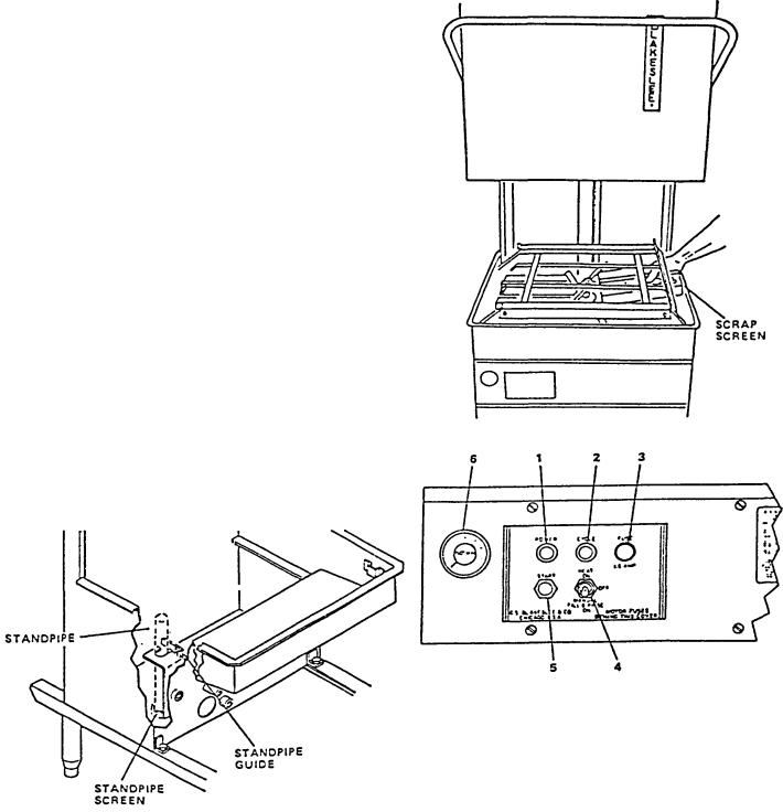
a. Close drain (s) by turning handle of drain valve (see figure 2-8) clockwise as far as it will go. Be sure standpipe guide is in position. (See figure 3-1), Place scrap screens in position. (See figure 3-2). Be sure all wash arms and lower final rinse arm(s) are in position and spin freely. Tighten (turn clockwise) lower spindle and upper wash rotor nut by hand.
b.Scatter the initial charge of detergent in scrap trays. Replenish as needed unless automatic detergent dispenser has been added by others.
c.Close the counterbalanced three way door.
d.Fill dishwasher tank with water. Flip HEAT/FILL switch item 4. Figure 3-3 to "FILL" (down) position. Leave it in this position for 3 minutes to fill tank. Flip HEAT/FILL switch to "ON" (up) position
to turn on tank heater.
e. Observe wash tank thermometer item 6, figure 3-3. It should
register between 150)-160)F. If. after a short period of time. this temperature is not attained adjust thermostat in control box (figure 2- 9.)
NOTE: ADJUSTING THE THERMOSTAT IS A USER FUNCTION AND IS NOT COVERED UNDER WARRANTY.
3-2. AUTO TANK FILL-Optional
If machine is equipped with optional automatic tank fill. machine will start filling with water automatically when machine "HEAT/FILL" switch is flipped "ON" (up). Wait approximately 3 minutes for machine to fill. NOTE: This option will automatically keep water to within 3 inches of
Figure 3-1. Standpipe Guide
SECTION 3
OPERATION
the top of the standpipe as long as the machine is on. When the machine is cycled, the final rinse water will bring the wash water up to the lop of the standpipe.
Figure 3-2. Installing Scrap Screens
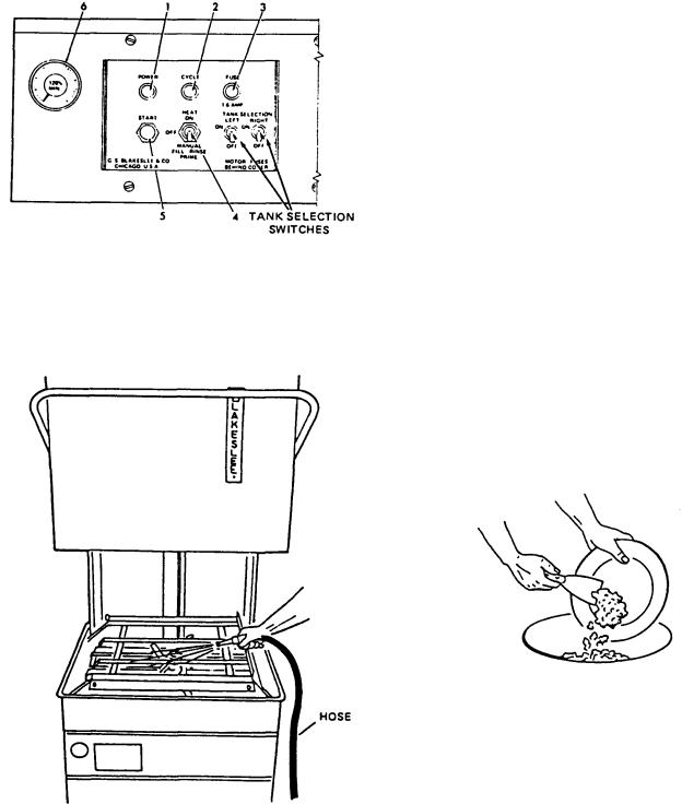
Figure 3-3. Standard Front Panel and Thermometer Single
and Double D8
1. |
Red Power Light |
5. Cycle Start Push Button |
2. |
Amber Cycle Light |
Switch |
3. |
Fuse |
6. Thermometer |
4.Heat On/Manual Fill and Rinse Switch
3-3. TIMED TANK FILL (Optional)
HEAT/FILL switch, for this option, is a spring return type. To activate Timed Tank Fill flip HEAT/FILL switch to "FILL" position and hold for 2 seconds. Switch will return to "OFF" position by spring action. Timer continues to fill tank.
NOTE: This lever should only be depressed at beginning of an operation when the machine does not have any water in it. After the machine is operating the final rinse water will keep the tank full of water.
Figure 3-3A. Front Panel and Thermometer (Shown with optional tank selection switches) DD8 Only
3-3A. TANK SELECTION (Optional on DD8 Only)
This option enables either left, right or both tanks to be operated during each automatic or manual cycle. It enables an operator to cycle only one tank during non rush periods. In most cases, it also enables the machine to operate on one tank even if the second tank is inoperable.
3-4. SOILED DISHTABLE OPERATION
If your dishroom personnel observe these simple work rules, your dishwashing operations will be fast and smooth, and your dish breakage held to a minimum.
Instruct your bus boys or waitresses that leftover food must be removed from dishes before placing them in stacks. See figure 3-5. This will assure maintaining cleaner wash water and reduced detergent costs.
Certain items are self-stacking, such as plates or trays. Food soil should be removed from these items and the plates should be placed in manageable stacks. An area on the soiled dish table should be designated as a "build-up-area." The stacks of dishes should be held in the build-up area and, if possible, stacks of like items should be placed next to each other. Racks can then be filled with like items when operator begins washing.
Some items will not readily stack, such as coffee cups, glasses, soup bowls. These items should be placed directly into racks so that they can be transported with a minimum of effort. See figure 3-6. In racks these items also are not exposed to breakage. Racks, when filled, should be placed in the build-up area. This organized, orderly separation of tableware is essential to dishroom efficiency and reduced breakage. THE BETTER ORGANIZED YOUR SOILED DISHTABLE, THE FASTER YOUR ENTIRE OPERATION, AND THE LESS YOUR BREAKAGE COSTS.
Silverware should be soaked in a sink or container to keep food particles from drying. When ready for washing, the
Figure 3-5. Scrapping Dishes before Stacking
12

Figure 3-6. Build-up Area
silverware should be placed either in a flat rack or vertical silverware holder and sent through the dishwasher.
NOTE: When placing silver in flat racks, do not overload the rack. You should be able to see the bottom of the rack in many places after it is loaded.
IMPORTANT: As much as possible, keep soil from entering dishwashing machine. This will reduce detergent consumption and will make the machine easier to clean.
3-5. LOADING MACHINES
All plates of the same size should be washed at the same time to eliminate sorting dishes at the clean end of the machine. If possible, all glasses, cups, etc. should likewise be sent through the machine at the same time to eliminate rack sorting. The machine should be operated as close to 100% efficiency as possible for a brief period while the build-up area is being cleared. Dishes from the build-up area should be quickly processed through the machine so the loading operator can return to his normal scrapping and stacking function.
Better results can be obtained from a DD8 dishwasher if one tank is used exclusively for china and the other tank is used for glasses and silver.
3-6. OPERATING THE DISHWASHER
a.After filling the wash tank and adding detergent, raise the door and slide the rack into the dishwasher. (Center of both tanks in a DD8.)
b.Close the door (dishwasher has a safety switch figure 1-2 that will prevent the machine from operating if the door is open.)
c.Automatic Operation
Momentarily depress START button. Machine will automatically wash and rinse one rack of dishes. Automatic CYCLE light (figure 3-3) will be on during the entire automatic cycle. When the cycle is over, the light will turn off. If the door is opened during the automatic cycle, the machine will stop. The automatic cycle will have to be restarted when the door is closed again. This feature provides a complete cycle to insure proper cleaning of the rack of dishes or added articles.
To avoid being splashed, it is advisable to wait approximately 5 seconds before opening the door, after stopping the machine.
d. Manual Operation
Wash Cycle
The only time manual wash is necessary is because of a timer or some other electrical failure. Close the hooded door, flip HEAT/FILL switch to "ON," depress and hold START button. Minimum wash time is 45 seconds.
Rinse
On some rare occasion, it may be desirable to operate the rinse cycle longer than programmed in the timer. Simply flip the HEAT/FILL switch to "FILL." Machine will rinse as long as the switch remains in the "FILL" position. Not applicable with machine equipped with Timed Tank Fill (Optional). If the machine timer has failed and the machine is being operated manually, the ware must be rinsed for a minimum of 12 seconds after a normal wash cycle.
Figure 3-7. View of Racks with Door Raised (DD8)
13
3-7. SHUT DOWN and CLEANING
a.Turn off main power switch.
b.Flip HEAT/FILL switch to "OFF" position.
c.Drain machine by turning drain valve counterclockwise as far as it will go (figure 2-8). Raise washer door.
d.Clean your dishtables and rinse in fresh water. Be sure to leave scrap screens in machine while doing this.
e.REMOVE scrap screens, empty them, and clean with a scrub brush in sink. Place on dishtable. DO NOT hit sides of scrap screens on trash containers.
f.Inspect Revolving Wash Rotors for blockage of any opening and ease of rotation. Remove and clean if required (see para. 4-4.)
g.Lift retainer on stand pipe guide (figure 3-1).
14
Remove standpipe and screen. Clean thoroughly in water with wire brush.
h.Wash and clean INSIDE OF MACHINE using a hose. (See figure 3-4.)
i.Leave DOOR open to dry interior of machine.
j.Thoroughly clean dishwashing area.
k.Clean and refill Detergent Dispenser (if machine has this optional equipment) as instructed by your detergent supplier.
I. Replace standpipe and screen, flip stand pipe retainer lever in place.
Additional Blakeslee Racks
W-0-16428 .............. |
Multipurpose Rack |
W-0-16429 ................ |
Combination Rack |
4-1. MOTOR
No Lubrication required
4-2. PUMP
No Lubrication required
4-3. DOORS
No Lubrication required
4-4. WASH ARMS
a.Wash arms (upper and lower) should turn freely and continue turning for a few seconds after being whirled by hand.
b.If the scrap screens are not properly in place, obstructions, such as prune seeds or bones, may clog the wash arm nozzles. The wash arms are easily removed for cleaning.
c.To remove the lower wash arm, first lift off the rinse arm, then unscrew the spindle bearing pin (item 8, figure 6-4). Lift off lower wash arm.
d.The upper wash arm(s) is removed by removing the wash rotor nut (item 12, figure 6-6).
4-5. FINAL RINSE ARM & NOZZLES
a.The rinse nozzles will need frequent cleaning if the water contains much lime or other solids.
b.The hole in the rinse nozzle on the lower rinse arm may be cleaned with a wire and paper clip. Push the scale or obstruction into the rinse arm, then unscrew the end plugs and flush out the tubes by operating the rinse. The lower rinse arm
may be lifted straight off the bearing pin and thrust washer assembly.
c. The upper final rinse nozzles can be cleaned with a wire brush and by inserting the end of a paper clip thru the nozzle. Then remove the 1/2" pipe cap at the end of the final rinse line and flush out the line (item 28, figure 6-5).
4-6. PUMP MOTOR OVERLOAD PROTECTION
a. Wash Motor(s)
Wash Motor protection is provided by Slow -Blow type cartridge fuses. In the event a foreign article jams the pump impeller, the motor will draw an excessive amount of current and open (blow) the fuse(s). After clearing the foreign article from the pump, the fuse(s) must be replaced before the pump motor will operate.
WARNING: |
SEE FIGURE 6-11, ITEM 29 FOR LOCA - |
|
TION OF FUSES. |
SECTION 4 MAINTENANCE & LUBRICATION
IMPORTANT: |
An open (blown) fuse must always be replaced |
|
with the same size and type of fuse(s). |
|
INCREASING THE FUSE SIZE OR RATING WILL |
|
ELIMINATE THE MOTOR PROTECTION AND |
|
VOID THE MACHINE MOTOR WARRANTY. Refer |
|
to figure 6-11, items 1 thru 3A, for the proper fuse |
|
size. It is suggested that spare fuses be purchased |
|
and kept on hand. These fuses can be obtained |
|
from your Blakeslee parts distributor or authorized |
|
service agency. Refer to the authorized service |
|
distributor and service agency listing booklet that |
|
was packaged with the machine for the one in your |
|
area. |
4-7. TROUBLESHOOTING
WASH PUMP MOTOR WILL NOT START (EITHER TANK)
1.Automatic timer defective.
Operate wash pump manually (see paragraph 3-6d). If pump will run on manual but not automatic, this indicates a defective timer.
2.Motor overload fuses blown.
Check the three fuses for continuity (see items 1 thru
3, figure 6-11).
Check junction box above motor if not working.
NOTE: If overload fuses are blown (open) this indicates either a defective motor or a foreign object has jammed the pump impeller. Turn off power supply, drain tank and check and remove any obstruction in the tank and pump intake.
MACHINE WILL NOT START
1.Main source of power off. Check power supply from customer's fuse or circuit breaker.
2.Control fuse blown open. Check control fuse for , continuity.
3.Door safety switch not actuated or defective. Be sure door is fully closed and rear portion of door handle has activated (closed) the switch. (See figure 1-2).
NO TANK HEAT
1.HEAT/FILL switch not "ON" or defective. Flip the switch to "ON" position. If red "POWER" light comes on, switch is good. Check further.
2.Main gas valve, steam valve or electrical heating circuit breaker not turned on. Check.
15
3.Thermostat set too low or defective. Open control box and turn thermostat clockwise until heat comes on.
NOTE: If heat comes on, do not leave thermostat at this high setting. Adjust to obtain 150°-160°F wash tank temperature on wash tank thermometer (figure 2-12, page 8). If turning thermostat clockwise does not start the heating cycle, check for the following::
a.Defective thermostat
b.Defective Gas valve
c.Steam solenoid or heating contactor, whichever is on your machine.
d.Dirty line strainer
e.Steam pressure too low (should be 10 Ibs. min.)
f.Defective steam trap (steam coil heated machine only)
NOTE: The heater is designed to maintain a temperature only. Door of dishwasher should always remain closed when machine is on but not being used.
WASH TANK WATER FOAMING
1.Wash tank water very dirty. Change wash tank water.
2.Poor pre-scrapping procedure. Scrap dishes better.
3.Excessive protein being put into dishwasher.
4.Improper detergent. Check with detergent representative.
POOR WASHING RESULTS
1.Poor scrapping procedures. Scrap dishes better.
2.Scrap screens blocked with soil. Empty screens.
3.Machine water dirty or contaminated. Change water.
4.Wash tank water temperature too low (See section 2-8)
5.Detergent dispenser empty. Fill dispenser.
6.Pump impeller clogged. (Refer to para. 2-5 pump motor.)
7.Wash pump running backwards. (Refer to para. 2-5 for pump rotation.)
8.Wash rotor clogged and/or not rotating. (Refer to para. 4-4 on wash rotor.)
9.Water conditioner causing spotting. Consult with detergent representative.
10.Dishes or silver improperly racked. Refer to para. 3-4 for operating instructions.)
11.Poor final rinse. Refer to para. 2-6.
NO FINAL RINSE
1.Line strainer dirty or sticking final rinse solenoid
valve. For proper operation, the solenoid valve must be free of foreign material at the valve seat. A critical period for a valve is soon after installation. Pipe compound or metal shavings from the installation may lodge at the valve seat and prevent the valve from completely opening or closing. A dirty line strainer (see figure 2-4) will also allow foreign material to pass.
REMEDY
Shut off the water supply and using a wrench, unscrew the end of the line strainer and drain. Clean and replace line strainer and cap. Operate final rinse. If final rinse still does not operate, turn water supply off again and unscrew bonnet of solenoid valve and clean. If after doing the above, the final rinse continues to malfunction, call your Blakeslee service technician.
INSUFFICIENT RINSE TEMPERATURE
Final Rinse
1.Final rinse booster turned off (remote mounted booster only).
2.Separate electrical supply to electric booster turned off.
3.Booster inoperative or booster thermostat set too low.
4.Adjust thermostat (refer to figure 2-9). Optional equipment (see section on boosters).
5.Water temperature of building supply water to booster too low.
6.Water supply line pressure from booster to dishwasher too low or not insulated to prevent heat loss.
7.Steam boosters only.
a. Insufficient steam supply to booster (minimum of 10 Ibs. flow pressure required).
a. Defective steam trap.
c.Condensate line not level or going down.
POOR FINAL RINSE RESULTS
1.Water supply pressure too low (must be 15-25 Ibs. flow pressure) (See para. 2-6.)
2.DD8 supply line size too small. Flow rate for DD8 is 18 GPM. Incoming water supply line should be 1" inside diameter.
16
3.Final rinse temperature too low. (See troubleshooting NO FINAL RINSE TEMPERATURE.
4.High time content or other foreign material in the water. High lime content or other foreign material will cause severe spotting. Consult your detergent representative for possible remedies.
5.Final rinse nozzles clogged. See para. 4-5 on cleaning final rinse nozzles.
6.Dirty wash water in dishwasher. Clean dishwasher.
DISHWASHER TANK(S) NOT HOLDING WATER
1.Drain valve(s) open or not fully closed. Turn valve(s) clockwise until it hits a positive stop.
2.Foreign material around drain seat preventing positive sealing of drain plug. Clean dishwasher and drain screen. (See para. 3-7).
3.Worn or damaged standpipe drain plug. Clean or replace.
DISHWASHER WILL NOT DRAIN
1.Clogged drain screen. Empty dishwasher by bailing water out of wash tank with pan, etc. Clean screen.
2.Customer's drain line plugged or too small. Consult your local plumber.
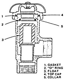
VACUUM BREAKER LEAKING
1.Deposits on the float will prevent operation of the vacuum breaker. Shut off water supply and remove the threaded top cap
(4) (figure 4-1). Lift off the
Figure 4-1. Vacuum Breaker
collar (5) with the "0" ring (2), then remove the gasket
(1). Withdraw the float (3) and clean thoroughly. At reassembly, make sure the "0" ring is not damaged and is properly seated in its groove.
Genuine Blakeslee Repair Kits that are available for these vacuum breakers:
W-1-12357 (Sloan Valve)
W-1 -12351 (Febco Valve)
W-1-14835 (Consolidated Valve)
Please specify if your valve is manufactured by Sloan or Febco. You will find the name on the cap.
17
 Loading...