

Page 1
BLAKESLEE
OWNER’S
MANUAL
Division of Blako Inc.
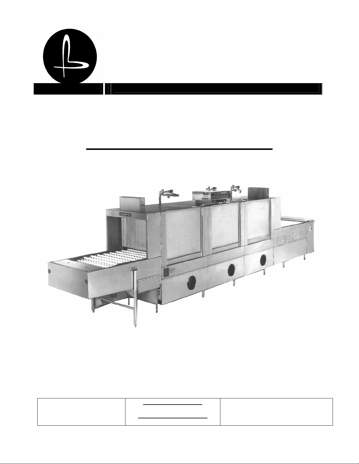
FLIGHT – TYPE DISHWASHER
I.R.S. INTEGRATED RECIRCULATING SYSTEM DESIGN
1844 South Laramie Avenue
Chicago, IL 60804
Phone (708) 656-0660
Fax (708) 656-0017
www.blakesleeinc.com
service@blakesleeinc.com
1149 Bellamy Road North Unit 19
Scarborough, Ontario Canada M1H1H7
Phone (416) 751-2625
Fax (416) 751-8539
Revised 8/2005
Page 2

NOTES
Page 3
CONTENTS
INTRODUCTION . . . . . . . . . . . . . . . . . . . . . . . . . . . . . . . . . . . . . . . . . . . 1
I DESCRIPTION . . . . . . . . . . . . . . . . . . . . . . . . . . . . . . . . . . . . . . . . . . . . 2
II OPERATION . . . . . . . . . . . . . . . . . . . . . . . . . . . . . . . . . . . . . . . . . . . . . 9
III CLEANING OF MACHINE. . . . . . . . . . . . . . . . . . . . . . . . . . . . . . . . . . . . . . . 15
IV PREVENTATIVE MAINTENANCE AND MINOR REPAIR . . . . . . . . . . . . . . . . . . . . . . 18
V USE OF ADDITIONAL EQUIPMENT . . . . . . . . . . . . . . . . . . . . . . . . . . . . . . . . . 23
VI PARTS LIST. . . . . . . . . . . . . . . . . . . . . . . . . . . . . . . . . . . . . . . . . . . . . . 43
Introduction
GENERAL.
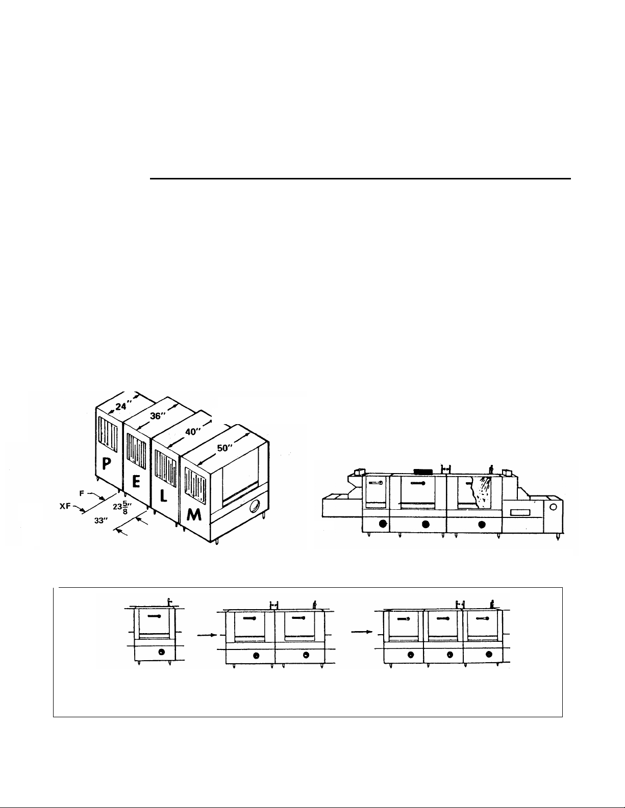
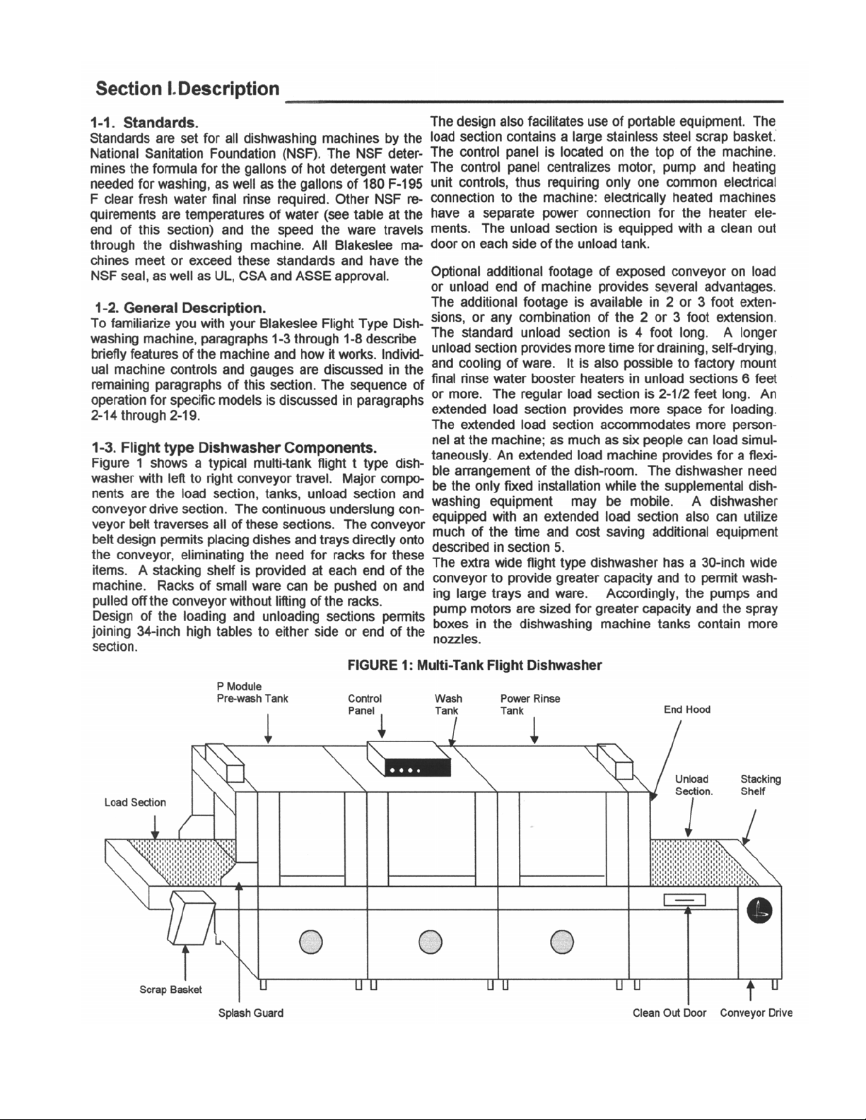
The Blakeslee Flight Type dishwashing machine is
available in many models. Each model is developed from
one or more of the five basic modules (or tanks) shown in
figure A. The P tank (24” long) which is the smallest is
used only as a PRE-WASH tank and is always fitted to
another tank as shown in figure B. The other four tanks
are identified by their length. Any E, L, or M module can
be a complete dishwasher in itself, or can be used as a
pre-wash, wash or power-rinse tank in a multi-tank unit
(see figure C). The Flight Type dishwasher is available in
two widths; the standard width machine has a 20-inch
conveyor; the extra wide model has a 30-inch conveyor.
EXPLANIATION OF MODEL DESIGNATION.
The Blakeslee Model designation indicates which tank, or
tanks, are used to build a particular machine. A Model F-E
FIGURE A. Dishwashing Machine Modules
Model F-E
Dishwasher indicates that a single E tank (36”
long) is the complete dishwasher. The Model FEE Dishwasher consists of two E tanks, one of
which is a wash tank and the other a power-rinse
tank. When a pre-wash is desired, the P tank is
added and the model becomes the F-PEE
Dishwasher. If a larger capacity dishwasher is
desired, a C, E, L, or M tank can be used as the
pre-wash in a three tank machine. When adding
the third tank to a F-EE machine, it becomes a
Model F-EEE Dishwasher.
CONVEYOR DIRECTION.
When your order was placed, you specified the
direction of conveyor travel. If the dishes enter the
machine on the left, we refer to the machine as
having L to R feed. Similarly, if the dishes enter
on the right, the machine has R to L feed. The
Illustrations included in this manual are of
machines with L to R feed, unless otherwise
noted.
FIGURE B. Dishwashing Machine with “P” Tank
Model F-EE Model F-EEE
F-L F-LL F-LLL
F-M F-MM F-MMM
FIGURE C. Dishwashing Machine Model Designations
1
Page 4
2
Page 5

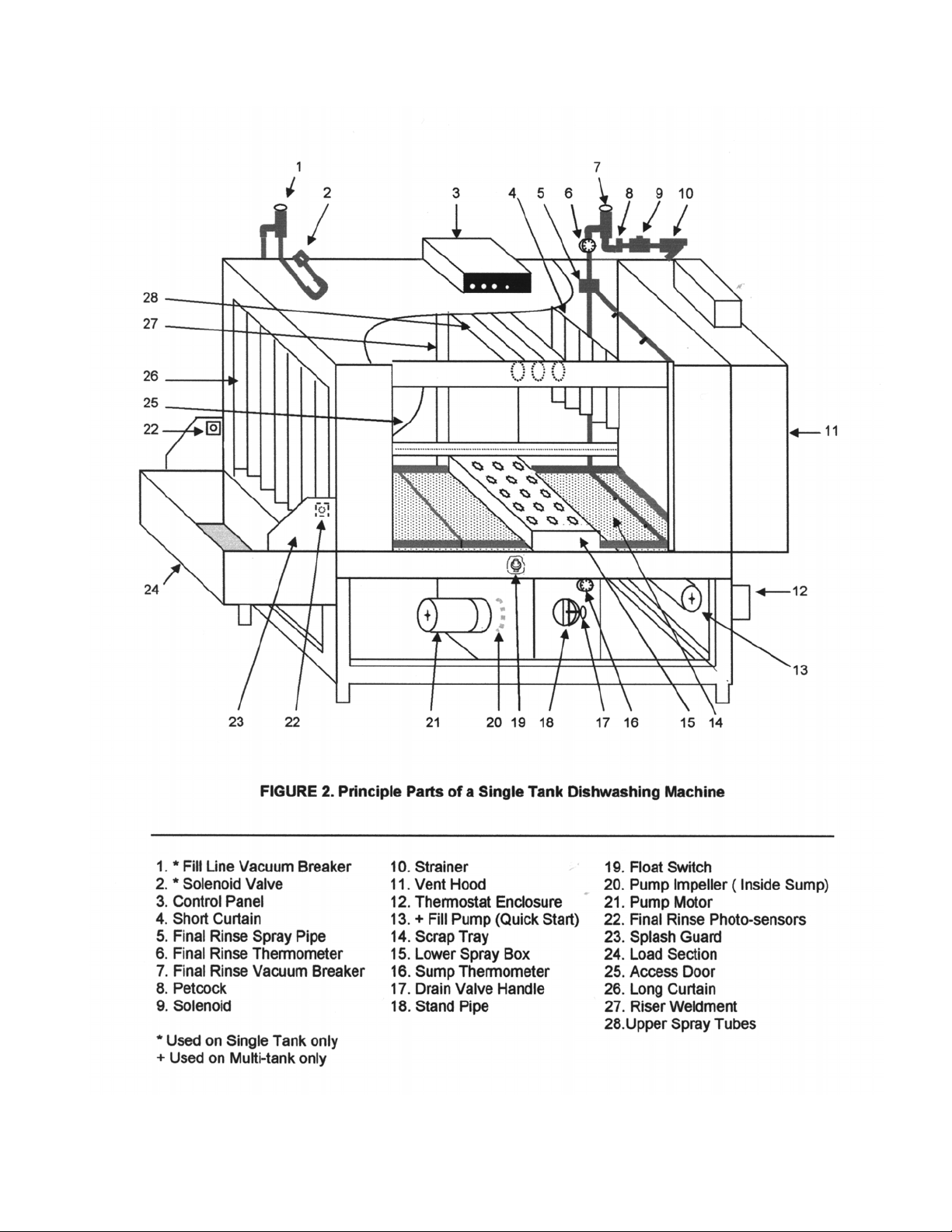
1-4. Single Tank Dishwashing Machine.
Figure 2 identifies the principle parts of a typical single
tank dishwashing machine. The machine shown has
Left to Right feed. The stainless steel tank is
supported on a sturdy base and has adjustable legs.
All interior parts are of stainless steel, or plastic
construction to resist effects of present day detergents
and cleaning chemicals. Curtains (26, figure 2) and a
splash guard (23) at the entrance and exit prevent
excessive splashing in the work room. A short curtain
(4) separates the washing and rinsing areas on
models without power-rinse tanks. All curtains are
easily removed for thorough cleaning. The large
access door (25) lifts to allow quick cleaning and
inspection of the dishwasher. The scrap trays (14)
slide out easily through the access door area. The
control panel (3) centralizes motor, pump, and heating
unit controls. Electrically heated machines have a
separate power connection for the heater elements.
1-5. Multi-Tank Dishwashing Machine.
Since Blakeslee dishwashing machines are developed
from the module concept, the multi-tank machine
includes all of the features outlined in the preceding
paragraph for the single tank machine.
The primary advantages of a multi-tank dishwashing
machine are the increased economy and capacity.
The inclusion of a pre-wash tank increases economy
by reusing overflow detergent wash water, thereby
reducing detergent cost. Similarly, the power rinse is
added to increase economy by pre-rinsing the dishes
with water accumulated from the fresh water rinse,
thereby reducing the amount of fresh final rinse water
needed to cleanse the already pre-rinsed dishes.
Capacity is increased by the addition of a full sized
pre-wash or power rinse tank since conveyor speeds
are then faster for multi tank dishwashers. (Note:
capacities are determined by the National Sanitation
Foundation.)
1-6. Wash Cycle.
Washing dishes requires two basic operations: first,
the washing second, the rinsing. This paragraph
describes the path of the wash water from the time it
enters the machine through the complete wash cycle.
This unit has auto-matic tank fill & water level control.
When the power switch is turned on, fresh water
enters the dishwashing machine at the fill valve (2,
figure 2) at the top of the machine. The water passes
through the vacuum breaker (1) to internal piping. The
vacuum breaker is a safety device designed to
prevent contaminated water from the dishwashing
machine being siphoned back into the fresh water
supply lines if water supply pressure fails. The internal
piping directs the water into the tank. When the tank is
filled to the proper level, and deter-gent added, a float
switch stops the fill, and turns on the tank heat. The
tank heat is controlled by a thermostat (12).
The sump thermometer (16) indicates the wash water
temperature. The wash cycle begins when the water is
heated and the conveyor is manually started. The pump
(20) directs the wash water through the riser weldment
(27) at the rear of the machine. Upper spray tubes and a
lower spray box are attached to the vertical riser.
Nozzles on each spray tube, and spray box direct wash
water at the dishes. Scrap trays (14) on either side of the
lower spray box prevents dislodged food particles falling
into the tank. The water return’s to the tank where it is
ready to start the wash cycle again. A hollow standpipe
(18) permits overflow water to flow down the drain. The
standpipe permits overflow water to skim heavy soil, etc.,
that floats on top of the wash water, and carry it down
the drain.
1-7. Final Rinse Cycle.
The final rinse water must always be fresh and hot
(within a range of 180 F to 195 F). Hot rinse water enters
the dishwashing machine at the strainer (10) and final
rinse solenoid valve (9). The water travels through the
vacuum breaker (7) and comes in contact with the final
rinse thermometer (6). The thermometer indicates the
temperature of the water entering the spray pipes (5).
The spray pipes contain small nozzles sized and
positioned for application of an even spray across the
conveyor. Final rinse water is never allowed to run
continuously. The final rinse photo-sensor (22) located
on the entrance of the machine controls the solenoid (9)
turning it on to coincide with the ware entering the final
rinse.
1-8.Quick Start.
Quick Start utilizes the 180° water from the final rinse as
an additional source to fill the tanks This system is
designed to give you a much shorter start-up time by
significantly decreasing the time necessary for the water
to come up to temperature. See paragraph 2-1.
1-9. Conveyor Drive Mechanism.
The underslung links of the conveyor belt are supported
by ½ inch stainless steel rods for standard and x-wide
machines. Rollers located on the ends of the rods
engage the drive sprockets attached to the shafts at
each end of the dishwashing machine. Figure 3A shows
the 48 tooth drive chain sprocket that is mounted in the
head shaft in the conveyor drive section. The chain is
driven by a ½ HP motor through a speed reducer.
A micro switch in the drive unit provides overload
protection for the conveyor. If a conveyor jam occurs,
the drive chain exerts a force on the lever arm, (see
figure 3A). The lever arm moves to trip the micro switch
open, causing the conveyor to stop. A spring is
connected to the lever arm and spring tension is
adjusted at the time of installation. Spring tension is set
so that when a fully loaded conveyor jams, the micro
switch opens.
3
Page 6
4-
Page 7
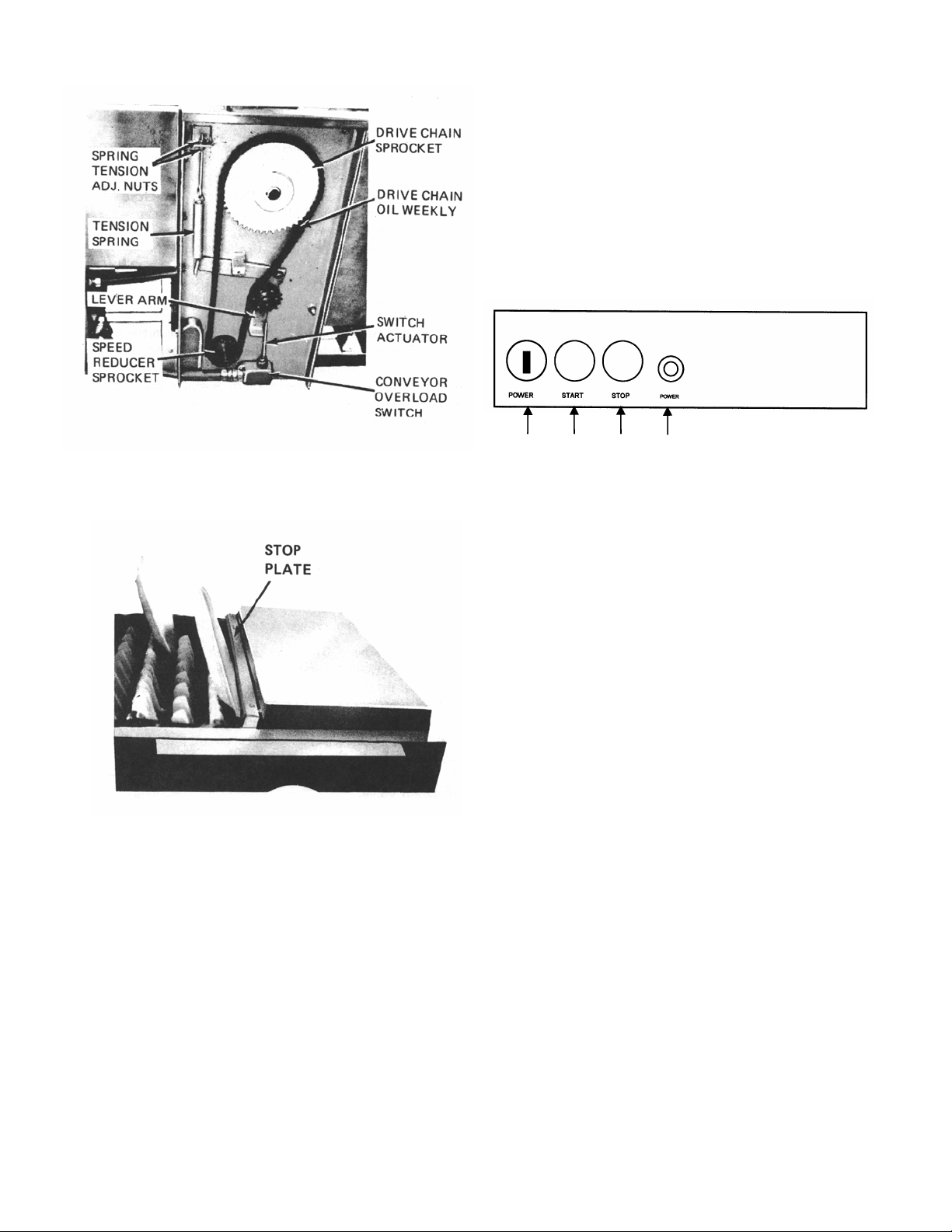
As the stop plate moves under the stacking shelf, it trips
the conveyor unload switch open and the conveyor
stops. After the clean item is removed from the
conveyor, the stop plate returns to its extended position
and conveyor operation automatically resumes.
FIGURE 3A. Drive Assembly
FIGURE 3B. Conveyor Stop Plate
The tail shaft in the load section is supported in
bearings which are mounted in take-up blocks. These
blocks can be moved by turning take-up screws to
remove slack from the conveyor belt. This adjustment
is performed at time of installation and the take up
screws are set in position with locking screws.
The stacking shelf on the conveyor drive section is a
part of the conveyor stop mechanism. When clean
ware or racks reach the discharge end of the conveyor
the conveyor stops. The clean item presses a spring
loaded stop plate. (See Figure 3B) this is the actuator
for the micro switch.
5
1-9. EXPLANATION OF CONTROLS.
1-10. Control Panel.
The control panel (figure 4) contains the motor switches,
and indicator light. These controls are used as follows:
1 2 3 4
FIGURE 4. Control Panel
1. Power on/off switch
2. Pumps & Conveyor start switch
3. Pumps & Conveyor stop switch
4. Power on indicator light
a. All Blakeslee flight conveyor dishwashers are
equipped with a door safety switch. The large inspection
door must be closed and the switch lever extended to
actuate the switch before any power can reach the
control panel.
b. The power ON/OFF selector switch provides electrical
power to the control panel. (1 figure 2)
c. The START and STOP pushbutton switches(2 and 3,
Figure 2) are the panel controls for the conveyor and
pumps electrical circuit. The START switch (2) is
pressed to start the pumps and conveyor drive motors,
and to provide electrical power to the final rinse limit
switch and solenoid valve when needed. Pressing the
STOP switch (3) disconnects power from the conveyor
and pumps electrical circuit and stops the conveyor and
pump motors.
d. Power light – Controlled by ON/OFF selector
switch. Light is on when switch is on.
e. Automatic low water cut-off. This circuit connects the
power supply to the pump and heat control circuits. If
this circuit is not operational, the pumps and heating
units will not operate. As the tank fills, the float ball
moves up. When there is approximately 2-1/2 inches, of
water in the tank the float switch (23 Figure 2) will close
and this circuit becomes operational. The pumps can
then be started and the tank heat will come on.
Page 8
The tank heat pilot lamp will not light unless the Low
Water Cut-Off circuit is operational. If the tank is
emptied or if the tank water level falls below 2-1/2
inches, the float will come down, opening the switch
and stopping the pumps and turning off the tank
heat. In the multi-tank machine, there is a float in
each tank except the P module pre-wash tank. If
one tank empties, the pumps and heat will not
operate for any of the tanks. Refilling the tanks will
automatically reconnect the pump and heat circuits.
1-11. Auxiliary Conveyor Start/Stop Switches
(OPTIONAL).
In addition to the conveyor controls on the control
panel, auxiliary SRART/STOP pushbutton switches
are factory installed at convenient customer
selected locations. These auxiliary switches
operate in the same manner as described in
paragraph 1-10c. Operating personnel can start or
stop the conveyor by pushing the appropriate button
on the control panel or any of the auxiliary stations.
1-12. Conveyor Unload Micro Switch.
The conveyor unload micro switch is under the
unload stacking shelf. This switch is tripped open
when clean ware reaches the discharge end of the
conveyor. When the switch is tripped, the conveyor
stops. Removing the clean item from the conveyor
automatically restarts the conveyor.
1-13. Conveyor Overload Micro Switch.
The conveyor overload micro switch is located in the
drive unit. This switch is automatically actuated
when the conveyor binds or is jammed. When this
occurs, the conveyor stops. After the cause of the
jam is determined and corrected, conveyor
operation is resumed by pressing the conveyor
START switch.
1-14. Final Rinse Photo-sensor and Solenoid
Valve.
The final rinse photo-sensor (22, Figure 2) When an
object moving on the conveyor breaks the infrared
beam between the sensors a signal is sent to the
microprocessor starting the final rinse timer. The
final rinse circuit is timed to activate the solenoid
valve (9 Figure 2) as the first item enters the final
rinse area and turn off the solenoid as the last item
leaves the final rinse area. The microprocessor
resets each time the infrared beam is broken
allowing the machine to stay in operation until the
final item is washed.
6
1-15. Drain Valve.
Each tank of the dishwashing machine is equipped with a
drain valve (18, figure 2). The drain valve handle is turned
clockwise ½ turn for the full closed position. This valve
must be closed when the tank is filled and must remain
closed while the dishwasher is operated. To empty the
tank, the drain valve is turned counter-clockwise ½ turn to
the open position. Each drain valve is equipped with a
screen. The screen requires frequent cleaning, as outlined
in paragraph 3-3.
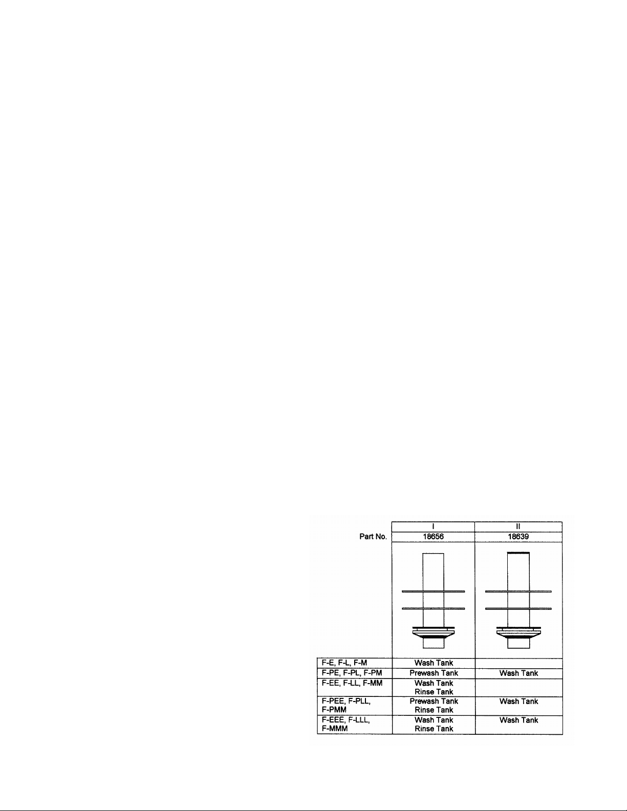
1-16. Standpipe.
A hollow stainless steel drain standpipe (22, figure 1) fits
into the drain valve seat in each tank. The standpipe is
sealed by a rubber drain plug which fits over the standpipe
and is secured by two stainless steel retaining rings. There
are two standpipe styles; the configuration used in a
particular tank is determined by the dishwashing machine
model as shown in figure 5. The standpipe must be
removed when cleaning the drain strainer. It is important
that the correct standpipe is installed in each tank.
For tanks equipped with standpipe style I, the length of the
standpipe determines the water level in the tank in which it
is mounted. When the water reaches the top of the
standpipe, it spills into the hollow standpipe and flows
through to the drain. This also permits overflow water to
skim heavy soil, etc, that floats on top of the wash water,
and carry it down the drain.
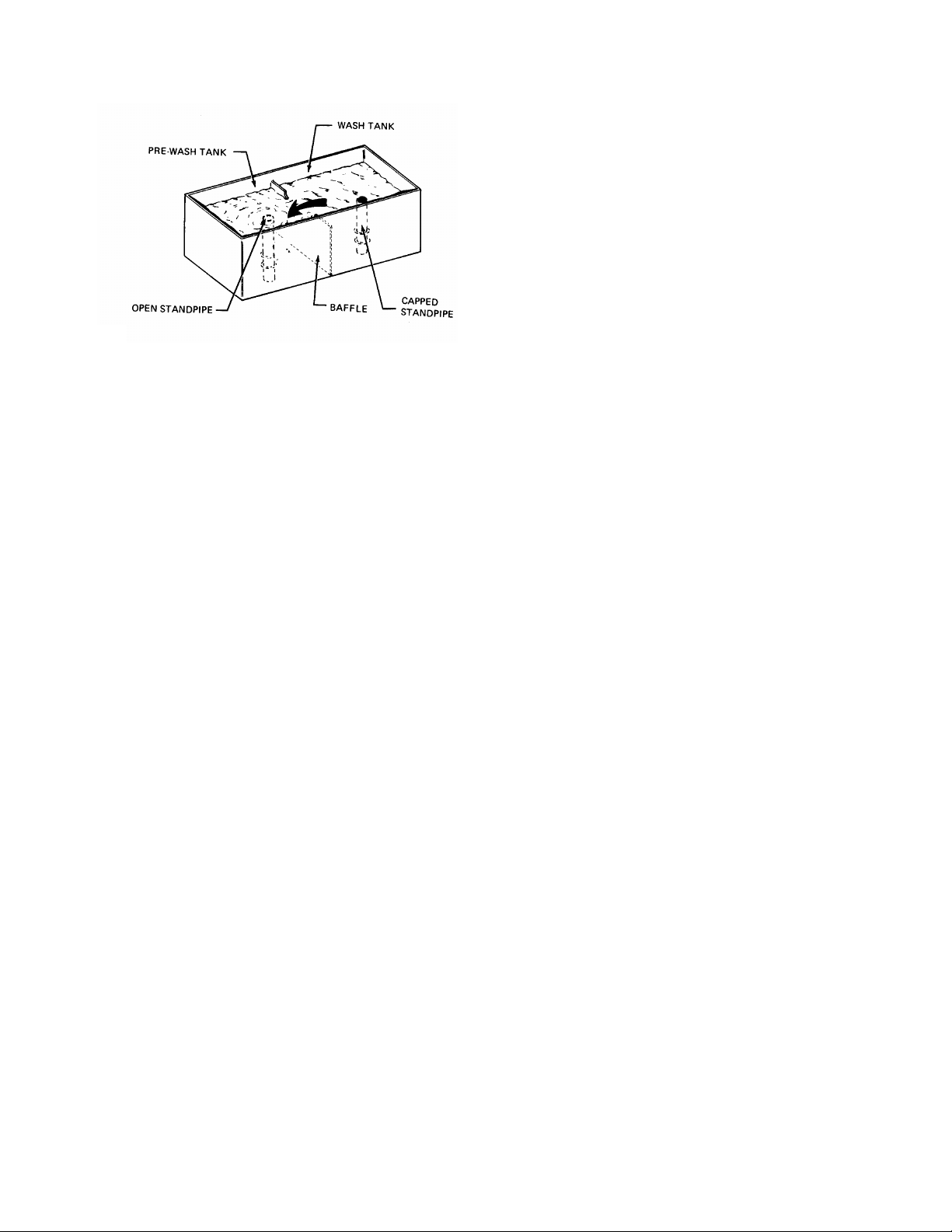
On standpipe style II, the top of the standpipe is capped.
These standpipes are used in wash tanks of machines
which include a pre-wash tank. This capped standpipe
prevents the excess water to drain. Instead, the excess
water flows over the cut out portion of the baffle (in the
tank common to both the wash and pre-wash tanks) into
the pre-wash tank, as indicated in figure 5 A. The pre-wash
tank is equipped with the style I standpipe.
FIGURE 5. Standpipes
Page 9
D. GAS. The gas heating system includes a gas control
valve and a separate low water cut-off float switch. Gas
enters the valve and is directed to the mixer heads on
the burners. Two burners are arranged along the bottom
rear of the tank. Burner orifice sizes are set at the factory
and usually require no further adjustments; larger or
smaller orifices for certain special gas B.T.U. outputs are
available. Safety devices include a gas flue, safety pilot
and built-in pressure regulator (natural gas only). Gas
will not flow through the gas control valve unless the pilot
light is lit, and there is water in the tank. Therefore, the
operator must check periodically that the pilot light has
not gone out, and relight it when necessary (refer to
paragraph 2 – 6) The gas control is actuated by the
control panel ON/OFF switch (1 figure 2) and is
FIGURE 5 A.
Baffle between Wash and Pre-wash Tanks only
1-17. Heaters.
A. ELECTRIC. The electric heating system is
controlled by the ON/OFF switch (6, figure 2) and is
monitored with a thermostat. This heating system
includes a contactor. The co ntactor is located toward
the rear of the machine on the right side (as viewed
when facing the access door). Some machines are
equipped with optional common connection electric
heat junction box. A separate power supply, properly
fused, must be connected to the contactor of each
heated tank.
After the switch is turned ON, no other control of the
system is required by the operator. The HEAT
indicator light (6) will glow when the heat circuit is on,
providing all tanks are filled with water.
B. STEAM INJECTOR. This heating system is
automatically controlled with a thermostat and
solenoid valve. Steam enters a strainer, passes
through the solenoid valve and a check valve and
enters the steam water heaters in the tank. The
solenoid valve is actuated by the control panel
ON/OFF switch (1, figure 4) and is monitored with a
thermostat. After the switch is turned ON, no other
control of the system is required by the operator. The
HEAT indicator light (6) will glow when the heat circuit
is on.
C. STEAM COIL. The steam coil heating system is
automatically controlled with a thermostat and
solenoid valve. Steam enters a strainer, passes
through the solenoid valve and enters the steam coil in
the tank where heat transfers to the tank water. A
steam trap at the coil exit connects to the condensate
drain. The solenoid valve is actuated by the control
panel ON/OFF switch (1, figure 2) and is monitored
with a thermostat. After the switch is turned ON no
other control of the system is required by the operator.
monitored with a thermostat. The HEAT indicator light
(6) will glow when the heat circuit is on, providing all
tanks are filled with water.
1-18. Line Strainers.
A. FINAL RINSE SYSTEM. The final rinse system
includes a strainer (10, figure 1) to protect the solenoid
valve (9, figure 1) from dirt. A good preventive
maintenance program must include periodic cleaning of
the strainer screen (refer to paragraph 3-5).
B. STEAM INJECTOR HEATING SYSTEM. This system
includes a solenoid valve protected with a strainer.
Periodic cleaning of the strainer is recommended (refer
to paragraph 3-5). The strainer is located at the steam
inlet side of the solenoid valve.
C. STEAM COIL HEATING SYSTEM. This system
includes a solenoid valve protected with a strainer.
Periodic cleaning of the strainer is recommended (refer
to paragraph 3-5). The strainer is located at the steam
inlet side of the solenoid valve.
1-19. Venting and End Hoods.
The end hoods are attached to the inlet and exit of the
dishwashing machine to reduce water splash and
exhaust the steam from the dishwashing machine area.
Exhausting the steam reduces the humidity in the
dishwashing department which contributes to more
efficient working conditions and quick self-drying of
dishes. Each hood must be connected to a ventilating
duct; vent opening on the hood is 4 x 16 inches.
Figure 1 shows the standard full-length unload end hood
with 10 inch wide side panels and standard load-end
hood. Extended full-length load and unload end hoods
with up to 16-inch wide side panels are available as an
option. Extended hoods provide more space for steam
collection and additional splash protection.
A damper in the hood is adjustable to control the
exhaust volume. To adjust the damper, place a wrench
on the flat of the damper rod and loosen the stop nut on
the side of the hood and turn the damper rod; tighten the
stop nut to lock the damper in position while holding rod
in position with wrench.
7
Page 10

The best damper position will vary according to the
size of the dishwashing room and machine. Allow
majority of steam to escape without loss of water
temperature in tanks. NOTE: if damper is open too
much heat will be lost from the tank.
CAUTION: Do not vent into wall or ceiling or
concealed space of a building.
1-20. Splash Guards.
Figure 1 shows splash guards attached to either the
end hoods or the end of the tank. These splash
guards are designed to divert water that is not
contained by the end hoods back into the load and
unload tanks.
1-21. GAUGES
1-22. Sump Thermometer.
Each tank of the dishwashing machine is equipped
with a sump thermometer (19, figure 1). This
thermometer indicates the temperature of the water in
the tank. NSF requirements for water temperatures
are indicated in the table at the end of this section.
After the dishwashing machine is filled with water and
the heating unit is turned on, the sump thermometer
should be observed periodically to assure that the
proper temperatures are being maintained.
1-23. Final Rinse Thermometer.
The final rinse thermometer (6, figure 1) is located
above the last tank of the dishwashing machine. This
thermometer indicates the temperature of the final
rinse water entering the machine. An NSF requirement
for final rinse water is 180 F – 195 F. Heating the final
rinse to 180 F is generally accomplished with a
booster heater. This heater was either purchased with
the dishwashing machine, or was part of the regular
kitchen equipment.
The heat from the final rinse water assures sanitation
and assists in heating the ware for rapid drying. During
dishwashing operation, the final rinse thermometer
should be observed periodically to assure that proper
temperature is being maintained.
8
1-24. Water Temperature Chart.
TYPE OF
MACHINE
OPERATION NSF MINIMUM
TEMPERATURE
SINGLE
TANK
SINGLE
TANK
W/PREWASH
2 TANK
2 TANK
W/PREWASH
3 TANK
Wash
Final Rinse
Prewash
Wash
Final Rinse
Wash
Power Rinse
Final Rinse
Prewash
Wash
Power Rinse
Final Rinse
Prewash
Wash
Power Rinse
Final Rinse
160 F
180 F - 195 F
110 F - 140 F
160 F
180 F - 195 F
150 F
160 F
180 F – 195 F
110 F – 140 F
150 F
160 F
180 F
110 F – 140 F
150 F
160 F
180 F – 195 F
1-25. Final Rinse Pressure Gauge. (OPTIONAL)
Properly heated final rinse water under pressure
between 15 to 25 psi (flow pressure) will effectively rinse
away detergent. The optional gauge is used to monitor
this flow pressure. Flow pressure is the indicated water
pressure with all final rinse valves open and the final
rinse in operation.
1-25-A. Final Rinse Pressure Gauge Petcock.
The final rinse system is equipped with a ¼- inch N.P.T.
petcock (8, figure 1). This device is used in conjunction
with detergent reps. & health inspectors test equipment.
Be sure petcock is closed (valve lever horizontal) before
removing plug to install equipment.
Page 11
Section II. Operation
5. Turn the ON/OFF switch in the control panel (1,
figure 2) on. The dishwashing machine will begin
filling. The fill indicator light should come on. Multi
tank machines fill using the rinse tank fill and the final
rinse. Water is pumped from the rinse tank to fill the
wash tank. See Quick Start paragraph 1-8. Quick
start is optional on single tank machines.
6. The machine will automatically stop filling when the
water reaches its proper level. At this point the heat
indicator light should come on.
7. Observe sump thermometers; minimum operating
temperatures are indicated on the thermometers, and
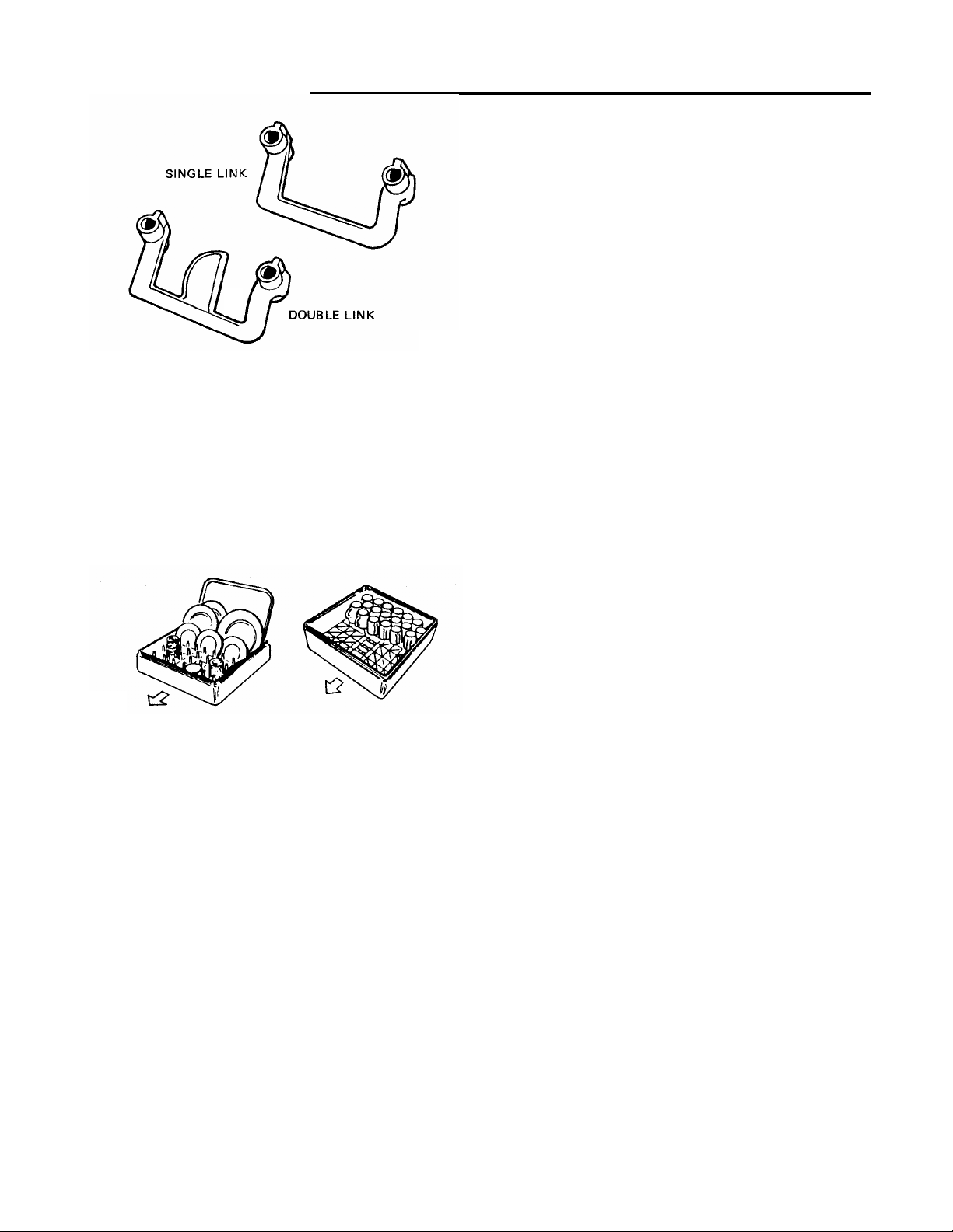
FIGURE 6. Flight Type Conveyor Link
Two types of racks are recommended: the multipurpose rack and the combination rack. There are
more holes in the bottom of the combination rack than
in the multi-purpose rack. The multi-purpose rack is
used for washing plates, saucers, trays (14 x 18 inch
maximum) and any ware except silverware. The
combination rack is used for washing silverware and
small ware such as cups, bowls and glasses.
MULTI-PURPOSE RACK COMBINATION RACK
PART NO. W-0-16428 PART NO. W-0-16429
FIGURE 7. Proper Loading of Racks
2-1. PREPARING MACHINE FOR OPERATION.
Perform the following steps to insure proper
dishwasher operation.
1. Check that clean scrap trays are in position on either
side of lower spray boxes. Be sure the curtains are in
position at dishwasher entrance, between the wash
and rinse areas of tanks, and at dishwasher exit.
2. Close tank drain valves and access doors.
3. Put correct amount of detergent in detergent
dispenser box. Observe the recommendations of the
detergent manufacture.
4. Be sure the door safety switch is pulled out so the
inspection door cannot be opened.
9
in the table at the end of section I.
8. Press the start switch on the control panel.
The dishwasher is now ready for loading.
2-2. LOADING MACHINE.
2-3. Conveyor Links.
The underslung conveyor links are suspended
between Stainless steel cross rods to form a flat belt
surface for easy loading and unloading. The double
link shown in figure 6 accommodates all regu lar and
extra-heavy ware that does not require racks. Platter
and tray sizes up to 14 x 18 inches maximum can be
placed directly in the links. Some dishwashing
machines, equipped with pre-flushers and used
primarily for washing trays, are equipped with a single
link conveyor belt. The slightly wider spacing of the
single link is especially suitable for trays, but does
accommodate other ware as well.
When loading the conveyor links, observe the
following: Place dishes in links with the soiled surface
tilted up. Place oblong items, such as platters and
trays, with the long side in the link. For example, to
wash a 14 x 18 inch tray, place the tray with the 18
inch side in the link.
2-4. OPERATING THE DISHWASHER.
Observe the following instructions to obtain maximum
performance from the dishwashing machine. Also
refer to paragraph 2-7 for helpful suggestions.
1. Whenever possible, instruct bus boys or wait staff
to stack the soiled dishes according to sizes as they
are brought to the soiled dish table.
2. Remove by hand, rubber scraper, or pre-washing
as much food particles left on the dishes as possible.
This will reduce pollution of water, insure the cleanest
possible wash water and lower detergent costs.
Page 12
3. Load the conveyor links and racks as described in
paragraphs 2-3 and 2-4. Slide the racks of soiled ware
onto the conveyor. Continue loading the machine with
soiled ware as fast as the conveyor allows.
4. Clean ware must be removed from the unload
section continuously. When ware is not removed from
the conveyor, the conveyor micro switch is tripped
causing the conveyor to stop.
5. Scrape and rack more dishes and “feed” the racks of
soiled ware to the machine as fast as it will take them
6. Continually check wash and rinse temperatures.
NOTE: For machines equipped with gas heating units, a
decreasing temperature may be caused by the pilot light
going out. Check that the pilot light is lit; when
necessary; relight as outlined in paragraph 2-6.
7. Be sure enough detergent is being added to the wash
water to keep it at an effective strength if an automatic
dispenser is not being used.
8. Repeat steps 2 through 8 until all dishes have been
washed.
10. Stop dishwasher (paragraph 2-5) and perform the
daily cleaning (paragraph 3-1).
2-5. STOPPING MACHINE AFTER OPERATION.
To stop the dishwasher, observe the following.
1. Press the STOP button.
2. Turn ON/OFF switch to the OFF position.
3. Open drain valve.
4. Clean machine (paragraph 3-1)
2-6 GAS PILOT LIGHTING INSTRUCTIONS.
The pilot burner is accessible from the right side of
the machine. Figure 8 shows the gas heat unit and
identifies the pilot burner and pilot lighting button.
Use a fireplace match, or a long piece of rolled – up
paper, to light the pilot burner as follows;
1. Slightly depress control knob if at PILOT position
and turn clockwise to OFF. Wait 5 minutes for all
unburned gas to vent. REMEMBER that LP gas does
not vent upward naturally.
2. Turn the control knob to PILOT, depress it
completely, and light the pilot burner. The knob must
be held down about one minute before the pilot
burner will stay lit after releasing the knob.
3. Turn the knob to ON. Gas burners should ignite. If
not, repeat above sequence.
10
Page 13

2-.7 HELPFUL HINTS
2-8. Proper Use of Flight Type Dishwashing
Machine.
The Flight Type dishwashing machine provides a direct
load, single-handling method of cleaning dishes. Since
this is a random load system, all sorting and stacking
can be eliminated before loading. The machine operators or waitresses simply remove the soiled dishes
from the container (tote box, tray, etc.) used to bring
the soiled ware into the dish room, scrape soil into
appropriate containers, and load the item in the
conveyor link or rack. Cups, glasses and miscellaneous
items like creamers, butter dishes, etc. are placed in
suitable racks. When a rack is full, it is placed on the
conveyor at random. Silverware is placed in a soak
sink. When a rack full of silverware is accumulated, it
is placed at random on the conveyor belt. Sorting and
stacking is done at the unload end. Clean ware can be
stacked on storage shelves or on portable carts for the
transportation to other areas in the dish room.
To obtain full advantage of the direct-load system, the
following equipment should be provided at the load end
of the machine: a suitable soil container (scrapping
trough, disposer, etc.); silver soak sink; and shelves (or
some convenient method) for loading racks and for
storing empty racks. For peak periods of operation,
shelves for temporary storage of entire tote boxes or
trays full of soiled ware are also convenient on the load
end of the machine.
2-9. Loading Precautions.
The dishwashing machine is built for washing dishes
and other tableware only, not for pots, pans or other
kitchen equipment. Any item that cannot be placed “in”
the conveyor link or dish racks without falling over
should not be cleaned in this machine.
Load racks properly. Glasses, cups and creamers
should be placed face down in the racks.
Care must be used not to overfill a silver rack. The
bottom of the rack must be visible in several areas
through the silver ware. If not, the rack is overfilled and
poor results will be obtained.
Small ware (saucers, dessert dishes etc.) that are
placed directly in the conveyor belt will not actuate the
conveyor stop mechanism. All small ware must be
placed in racks in order to trip the stop mechanism.
2-10. Dish Handling Techniques – Flight Machine
with regular Load Section
LOADING OPERATIONS. The Flight Type machine is
designed for the direct-load, single chandelling system
of cleaning dishes: whenever possible, use the
machine as described in paragraph 2-8. When the size
or layout of the dish room limits activity at the load
section, it may be necessary to perform the scraping or
rack loading operations at a separate location. When
rack loading is performed away from the load section,
consider establishing a soiled dish table. Instruct your
busboys or wait staff to arrange the soiled ware on the
dish table in an orderly manner as the ware is brought
to the table. There should be designated places for
depositing scraps, napkins, and soiled ware. In many
instances, cups, glasses, butter dishes, etc., can be
placed directly in the appropriate rack by the bus boys
or wait staff. Mobile equipment can be helpful to
convey the soiled ware to the dishwashing machine.
SCRAPING DISHES. Do a good job of removing left
over food from the dishes. Scrape dishes by hand, with
a rubber scraper, or by pre-washing before placing
them in the conveyor links or racks. Doing this job
properly helps to maintain cleaner wash water.
2-11. Dish Handling Techniques – Flight
Machine with Extended Load Section
LOADING OPERATIONS. The extended load machine
is best used as described in paragraph 2-8. The
extended load section provides ample space for
performing all of the loading operations and
accommodates three or more personnel at the same
time. The extended load machine is usually purchased
with optional equipment or arranged with existing
equipment, such as scraping trough, rack loading and
storage shelves, and a pre-flushing system. For proper
and efficient use of Blakeslee option items refer to
section V.
SCRAPING DISHES. Heavy soil must be removed
from the dishes before loading them into the links or
racks; a minimum of pre-scraping is required. A
machine equipped with a pre-flusher requires
practically no pre-scraping.
2-12 Detergents.
Detergents should be used according to the detergent
manufacturer’s recommendations. Their representative
knows the capabilities of their detergents and can
determine the proper treatment of your water for proper
use with their product. The wash water must be kept at
an effective strength to obtain good washing results.
Use a good detergent. Never use a foaming soap or
soap flakes. Ask your local detergent man for his help
and heed his advice.
2-13. BRIEF DESCRIPTION OF SEQUENCE OF
OPERATION.
The sequence of operation for various dishwasher
models is described in paragraph 2-14 through 2-16
and represented in figures 9 through 13. Many of the
parts referred to in these descriptions are shown in
figure 1 of this manual.
2-14 Single Tank Dishwashing Machine. (See Fig. 9)
WASH CYCLE. The pump directs the wash water
through the riser weldment at the rear of the machine to
upper spray arms and to a lower spray box. Nozzles on
the spray arms, and spray box direct the wash water at
the dishes.
11
Page 14
Trays on either side of the lower spray box prevent
dislodged food particles falling into the tank. The water
returns to the tank, where it is ready to start the wash cycle
again. The hollow standpipe permits overflow water to flow
down the drain and acts as a surface skimmer.
FINAL RINSE CYCLE. Hot final rinse water enters
the machine at the strainers and solenoid valve. The
water travels through the vacuum breaker and enters
the spray pipes. Nozzles on the spray pipes direct
the rinse water at the dishes.
FIGURE 9. Single Tank Water Distribution Diagram
2-15. Single tank with P-Module Pre-Wash (See Fig.11).
PRE-WASH CYCLE. The pre-wash tank is filled with
overflow water from the wash tank. The pre-wash water is
pumped through the riser weldment at the rear of the
machine where it enters an upper spray arm. (a lower
spray arm is available as optional equipment) Nozzles on
the spray arm direct the pre-wash water at the dishes. A
scrap tray below the conveyor track prevents dislodged
food particles falling into the tank. The water returns to the
tank, where it is ready to start the pre-wash cycle again.
The hollow standpipe permits overflow water to flow down
the drain.
WASH CYCLE. The pump directs the wash water
through the vertical riser at the rear of the machine to
upper spray pipes, and to a lower spray box. Nozzles
on the spray arms and spray box direct the wash
water at the dishes. Scrap trays on either side of the
lower spray box prevent dislodged food particles
falling into the tank. The water returns to the tank,
where it is ready to start the wash cycle again. The
capped standpipe prevents the overflow water
flowing down the drain. Instead, the water is forced
to overflow into the pre-wash tank.
FINAL RINSE CYCLE. The final rinse cycle for this
machine is identical to the final rinse cycle described
in paragraph 2-12.
12
FIGURE10. Single Tank with P- Module Pre-Wash Water Distribution Diagram
Page 15
2-16. Two Tank Dishwashing Machine (See Fig. 11).
WASH CYCLE. The pump directs the wash water
through the riser pipe at the rear of the machine to
upper spray pipes and to a lower spray box. Nozzles on
each spray arm and spray box direct the wash water at
the dishes. Scrap trays on either side of the lower spray
box prevent dislodged food particles falling into the
tank. The water returns to the tank, where it is ready to
start the wash cycle again. The hollow standpipe
permits overflow water to flow down the drain.
POWER RINSE CYCLE. The pump directs the rinse
water through the riser weldment at the rear of the
machine to upper spray arms and a lower spray box.
Nozzles on each spray arm and spray box direct the
rinse water at the dishes. Scrap trays on either side of
the lower spray box prevent dislodged food particles
falling into the tank. The water returns to the tank,
where it is ready to start the rinse again. The hollow
standpipe permits overflow water to flow down the
drain. The rinse water is replenished with used final
rinse water.
FINAL RINSE CYCLE. Hot final rinse water enters the
machine at the strainer and solenoid valve. The water
travels through the vacuum breaker and enters the
spray pipes. Nozzles on the spray pipes direct the rinse
water at the dishes. The used final rinse water falls into
the power rinse tank.
FIGURE 11. Two Tank Water Distribution Diagram
2-17. Two Tank with P-Module Pre-Wash (See Fig.12).
PRE-WASH CYCLE. The pre-wash cycle for this machine is
identical to the pre-wash cycle described in paragraph 2-13.
WASH CYCLE. The pump directs the wash water through
the riser weldment at the rear of the machine to upper spray
arms and a lower spray box. Nozzles on each spray arm and
spray box direct the wash water at the dishes. Scrap trays
on either side of the lower spray box prevent food particles
falling into the tank. The water returns to the
tank, where it is ready to start the wash cycle
again. The capped standpipe prevents the
overflow water flowing down the drain. Instead,
the water is forced to overflow into the pre-wash
tank.
POWER RINSE CYCLE. The power rinse cycle
for this machine is identical to the power rinse
cycle described in paragraph 2-14.
FINAL RINSE CYCLE. The final rinse cycle for
this machine is identical to the final rinse cycle
described in paragraph 2-14.
FIGURE 12. Two Tank with P – Module Pre-wash Water Distribution Diagram
13
Page 16

FIGURE 13. Three Tank Water Distribution Diagram
2-18. Three Tank Dishwashing Machine (See Fig. 13).
PRE-WASH CYCLE. The pre-wash tank is supplied with
overflow water from the wash tank. The pre-wash water is
pumped through the riser pipe at the rear of the machine
where it enters upper spray pipes and lower spray box.
Nozzles on each spray pipe and spray box direct the prewash water at the dishes. Scrap trays on either side of the
lower spray box prevent dislodged food particles falling into
the tank. The water returns to the tank, where it is ready to
start the pre-wash cycle again.
14
The hollow standpipe permits overflow water to flow
down the drain.
WASH CYCLE. The wash cycle for this machine is
identical to the wash cycle described in paragraph 2-
15.
POWER RINSE CYCLE. The power rinse cycle for
this machine is identical to the power rinse cycle
described in paragraph 2-14.
FINAL RINSE CYCLE. The final rinse cycle for this
machine is identical to the final rinse cycle described
in paragraph 2-14.
Page 17

Section III Cleaning of Machine
g
3-1. DAILY CLEANING
After each meal period and at the end of each day, the
dishwashing machine should be stopped and the
following cleaning procedures performed. A hose
attached to a faucet in the hot water supply line makes
the cleaning of your machine and dish tables much
quicker and easier. The hose can be stored neatly
coiled on a hook beneath the dish tables.
1. Stop the dishwashing machine as outlined in
paragraph 2-5. Check that heaters are off, tanks are
drained, and drain valves are open.
2. For a machine with regular load section, lift the clean
out door at the end of the section and remove soil from
inside the section. Clear the beehive strainer on the
drain to the scrap basket. Close the clean out door and
hose down the interior of the load section. Leave the
scrap basket in the machine during this operation.
For a machine with extended load section, hose the
interior of load section directing the scraps to the
opening in the load section that connects to the soil
container (trough disposer or basket, recirculator, etc.).
Clean the auxiliary equipment after the dishwashing
machine has been cleaned; cleaning instructions for
Blakeslee equipment is included in Section V.
3. Lift the clean out door on each side of the unload
section and remove soil from inside the section. Clear
the beehive strainer on the drain to the scrap basket.
Close the clean out door and hose down the interior of
the unload section.
4. Remove curtains and scrub them in a sink (see figure
14). The curtains can be installed in the dishwasher to
dry, but it is best to hang them elsewhere. The
dishwashing machine will dry and air out better without
the curtains in place.
5. Remove scrap trays and empty them into a sink.
Flush the trays with a hose or clean them with a scrub
brush. When emptying the trays, do not knock them on
disposal cans; knocking the trays will bend them out of
shape and they will not fit properly in the dishwasher.
FIGURE 14 Scrubbing Curtains
6. Check and clean the spray box/tubes as necessary. To
remove them refer to figure 14 and loosen the pilot screws
retaining the spray box/tubes. Slide the spray box and
tubes out of the machine. Check the gasket and seals for
signs of wear (paragraph 4-6). Dislodge anything stuck in
the nozzles by pushing the material back and into the box
or tube. Wash the spray box or tube, flushing the
materials out of the inlet hole.
FIGURE 14 Spray Box Mountin
7. Hose and scrub the inside of the dishwashing machine.
Do not direct hose up into the end hood ventilating ducts.
Use a damp cloth to wipe hood condensate baffle clean.
8. Remove access doors from each tank and clean both
sides of the door, a lip at the bottom tends to collect soil;
be sure to clean this area.
9. Clean the drain screen as outlined in paragraph 3-3.
10. Install the clean spray box and tubes in position in the
machine (refer to figure 14). Be sure to position the upper
spray tubes with the nozzles pointing down. When
installing the tubes and spray box, tighten pilot screw
finger tight only; do not apply excessive pressure.
11. Leave access doors open and leave scrap trays and
curtains on the dish table until preparing the machine for
operation. This allows the dishwashing machine to dry
and the operator will know that the machine has been
thoroughly cleaned.
12. Clean and fill detergent dispenser.
15
Page 18

3-2. PERODIC CLEANING.
The frequency with which the following cleaning
procedures should be performed depends on the hours of
dishwasher operation and the condition of the water in
your area. When intervals are specified (once a week,
once a month, etc.) they are recommended minimum
intervals and should be performed at least as often as
specified.
3-3. Drain Screen
The drain valve for each tank of the dishwashing machine
is equipped with a cylindrical stainless steel screen (6,
figure 15). When this screen is clogged with food
particles, the tank does not drain as quickly as it should.
Thorough pre-scraping of the ware will minimize screen
clogging. Cleaning of the screen should be performed
after a daily cleaning. Clean the screen in each tank as
follows:
1. Check that the heater is off and the tank is drained.
Position the drain valve in the closed position.
2. Remove the 3 wing nuts (20, figure 15) and pull the
drain case door (21) from the drain case. A gasket (22)
between the case and the door acts as a seal to prevent
leakage. If it is necessary to pry the door from the case,
be careful to avoid damaging the gasket.
CAUTION: The tank must be empty of water before
removing the drain case door. When drain case contains
hot water and the door is removed, the hot water will exit
at the door hole and could cause serious injury. If drain
screen is completely clogged, manually remove water
with a container through the access door from top of tank.
To gain access to the screen to unclog it, lift standpipe by
pulling it up, turning drain valve handle at the same time.
3. Lift drain standpipe (1) straight up to gain access to the
screen.
4. Lift the screen straight up off of the drain valve seat
(10) and clean it in a sink with a brush A bent or deformed
screen should be replaced with a new one.
5. Clean drain case interior and flush the drain valve with
clear water.
6. Install clean screen (6) on drain valve seat (10).
7. Lower the standpipe (1) into the drain valve seat. Do
not drop standpipe into position.
8. Be sure door gasket is in place on drain case, (22).
With the drain valve knob in closed position (white arc at
the (bottom), install the door on the case, locating the
cam on the knob shaft between the two collars on the
standpipe. The three mounting holes in the gasket and
door are not spaced equally and therefore the gasket and
door holes must be matched to the case studs
16
9. Assemble the three wing nuts (20) on the case studs,
applying equal pressure to the wing nuts until they are
snug; do not tighten these nuts with a wrench.
FIGURE 15. Standpipe and Drain Valve Shaft
1. Stand Pipe 12. Thermometer
2. Retaining Ring 13. Cam Shaft Assy.(14-18)
3. Washer 14. Cam Shaft
4. Drain Plug 15. Stop Pin
5. Washer 16. O-Ring
6. Screen 17. Knob
7. Screen retainer 18. Hex Nut
8. Stand Pipe Guide 19. Spacer
9. Hex Head Bolt 20. Wing Nut
10. Drain Seat 21. Door
11. Cam Shaft Assy. 22. Door gasket
3-4. Low Water Cut-Off Float.
For proper operation of the low water cut-off system, the
float in each tank must be free of detergent scum and lime
deposits. Daily cleaning and deliming will keep the float
reasonably clean. CAUTION: Do not use steel wool
cleaning pads.
Page 19

3-5. Line Strainers
Every dishwashing machine is equipped with a strainer
in the final rinse system (10, figure 2). In addition, each
steam heated machine (steam injector or steam coil) is
also equipped with a strainer at the steam inlet. The
following instructions apply to all of the strainers.
DELIMING REMOVABLE DISHWASHER PARTS.
The daily cleaning procedures will reveal when it is
necessary to delime such items as final rinse nozzles
and spray boxes.
Recommended procedure is to soak these parts in a
large sink containing a deliming product. Follow the
instructions of the deliming product manufacturer for
mixing the solution and length of time soaking. After
soaking, be sure to wash with detergent and rinse all
parts thoroughly to neutralize any deliming solution
remaining on the parts.
DELIMING DISHWASHING MACHINE. Cleaning of
the dishwashing machine interior with an appropriate
deliming preparation should be performed as
necessary to remove accumulated deposits in order to
FIGURE 16. Steam Injector Line Strainer
Once a month, clean the strainer as follows. Unscrew
the brass cap and remove the strainer screen. Brush
the screen or flush out dirt with fresh water. Install the
screen and attach the brass cap securely. A worn
screen should be replaced with a new one.
3-6. Final Rinse Nozzles.
Every 3 to 4 months, check and clean rinse nozzles as
necessary. If lime deposits have formed on the nozzles,
the nozzles should be removed from the spray pipes and
placed in a deliming solution (refer to paragraph 3-9).
3-7. Electric Heating Elements.
Lime deposits on electric heating elements cause poor
heating and premature burn out of the element. The
tank must be delimed as soon as lime scale starts to
build up on the element.
3-8. Steam Heating Coil.
A buildup of lime scale on steam heating coils drastically
reduces their heating efficiency. The tank must be
delimed as soon as lime scale is noticed on the coils.
3-9. Deliming Solution Precautions.
Some deliming preparations contain muriatic acid.
Muriatic acid is corrosive to skin as well as to clothing
and metals; it is very harmful if splashed in the eyes.
When using this acid, caution must be exercised and
maintain optimum machine performance. Most
dishwasher detergent representatives will instruct
owners on proper deliming procedures. When
deliming the machine, observe the following:
1. Turn on power to fill the dishwashing machine
tank(s) half full of water, turn off power. Then
add deliming solution, following the detergent
manufacturer’s recommendations.
2. After the deliming solution has been added to
the half filled tank(s), turn on power to
continue filling tank.
3. The conveyor must be operating during the
deliming process.
4. Allow the deliming solution to circulate for 15
minutes. If this15 minute operation is not
sufficient to remove deposits, operate for not
more than an additional 15 minutes.
Occasionally, there will be places in the
machine where some deposits still remain;
remove the softened-up deposit with a putty
knife or wire brush.
5. Turn off power and drain the Tank(s). Then
immediately refill the tanks with fresh water
and add detergent. Operate the machine 10
to 15 minutes to neutralize any solution left in
machine.
6. Drain the tank(s) again and flush them out
with a hose. NOTE: Certain deliming
solutions have a very high concentration of
acid that is harmful to vital components of your
machine (pump seals, plastic links, etc.) Be
sure to check with your detergent
representative or the manufacturer deliming
solution before using. If in doubt, contact your
local Blakeslee representative.
personnel should be acquainted with the risks and
hazards.
17
Page 20

Section IV Preventive Maintenance and Minor Repair
4.1 PREVENTATIVE MAINTENANCE.
A good preventive maintenance program ensures that
the dishwashing machine is kept in good operating
condition and lessens the chances of break-down.
Preventive maintenance means making systematic
inspections and adjustments at regular intervals. These
procedures should be performed as soon as the need
becomes apparent or at the specified intervals. More
frequent inspections and adjustments should be if
experience indicates that shorter intervals are required
due to operating conditions. In addition to the periodic
cleaning procedures of Section III, the inspections and
adjustments of paragraph 4-2 through 4-16
4-2. LUBRICATION.
The pump and drive motors contain ball bearings and do
not require lubrication. The conveyor drive chain and
gear reducer must be lubricated or checked as described
in the following paragraphs. CAUTION: When applying
lubricant, secure or lock main power in the OFF position.
Power must be off to the machine during lubrication
procedures to avoid accidental conveyor operation which
could result in physical harm to maintenance personnel.
4-3. Conveyor Drive Chain
Once a month, oil the drive chain (see figure 3).
Remove drive section panel and apply a few drops of oil
to the drive chain. Use straight 20-20w oil. Replace the
drive section panel.
4-3. Conveyor Drive Gear Reducer.
Once a month check gear reducer oil level. The oil plug
and oil drain plug are located on the gear reducer as
shown in (figure 17). The oil level should never be higher
than the upper plug. To add oil, remove the air vent and
fill screw (figure 17) and add oil through the vent hole.
Use a high quality compounded worm gear oil, Mobil
Extra Hecla Super or a comparable oil recommended by
your lubricant supplier. Install the air vent and fill screw.
After the first 100 hours of operation, and then after
every 2500 hours of operation or every 6 months,
change oil. Place a suitable container beneath the oil
drain plug. Remove plug and allow oil to drain from the
gear reducer. Install drain plug and fill reducer with fresh
oil until the oil starts to come out of the oil level plug.
Install level plug.
4- 4. V-BELT TENSION ADJUSTMENT
The conveyor drive gear reducer is driven by a notched
V-belt from the drive motor. The average belt will stretch
after a period of time. After the first 50 hours of
operation, and then periodically as experience indicates,
check the v-belt tension. Figure 18 indicates the proper
tension; belt deflection is ½ inch when a 3-pound force is
applied.
18
FIGURE 17. Conveyor Drive Gear Reducer and
Motor
To adjust the tension, loosen the locknut see figure
18) to permit turning the adjustment rod. Turn the rod
clockwise to tighten the belt; turn counterclockwise to
loosen the belt. Tighten the locknut after turning the
rod to maintain the proper tension.
FIGURE 18. Conveyor Drive Belt Tension
4-5. PREVENTING LEAKAGE.
The spray box gaskets and standpipe drain plug are
subject to wear, which results in leakage. The
following paragraphs contain replacement instructions
for these and similar items. Part numbers for
replacement parts are listed in Section VI of this
manual. For servicing of other leaks, contact your
local Blakeslee service agency.
4-6. Spray Box Gaskets
Poor washing results occur when the spray box/tube
gaskets or seals are worn and leaking. When the
spray box/tube is removed for cleaning, check the
gasket and seals (see figure 14) for signs of wear. If
they are worn or out of shape, replace with new ones.
To minimize gasket wear, when installing the spray
box and tubes after cleaning, do not apply excessive
pressure to the pilot screw.
Page 21

4-7. Stand Pipe Drain Plug
When cleaning the drain strainer (paragraph 3-3), check
the stand pipe drain plug (4, figure 15) for signs of wear.
If the plug is nicked or badly grooved, replace with a new
one. NOTE: Before installing new drain plug, apply a
light film of silicon sealant to the entire exterior
circumference of the plug groove.
4-8. Drain Cleanout Door Gasket
When leakage occurs around the drain case door, the
problem may be a worn drain cleanout door gasket.
However, first be sure the door was properly installed
(paragraph 3-3, steps 8 and9). When the drain strainer
is cleaned, check the gasket for signs of wear. If gasket
is worn, replace with a new one.
4-9 Impeller Guard
This unique device consists of a guard housing encircling
the pump intake and positioned ¾” from sump wall,
providing a circular opening that is larger than the
opening of the pump intake, Thus creating no restrictions
for water flow. Inside the circular guard housing there is
a guard disk of smaller dimension which allows
additional passage of water flow with minimum
restrictions. The location of guard housing and disc is
such that there is no straight entrance into the impeller
4-11. Flame Adjustments for Gas-Heated Tanks.
After the dishwashing machine is installed and gas
connections are made, the pilot and burner should be
adjusted to obtain desired tank temperatures. Refer
to paragraph 2-6 for pilot lighting instructions.
PILOT FLAME ADJUSTMENT. The pilot flame should
envelope 3/8 to ½ inch of the top of the thermocouple.
Remove the cover screw to gain access to the pilot
flow adjustment screw; see figure 8. Turn the
adjustment screw clockwise to decrease pilot flame;
turn counterclockwise to increase pilot flame. Be sure
to replace cover screw after adjustment to prevent
possible gas leakage.
BURNER FLAME ADJUSTMENT. The burner flame
must only touch the tank. On natural gas machines,
minor burner adjustment can be made by adjusting
the pressure regulator of the gas valve; on L.P. gas
machines, the customer’s gas pressure regulator can
be changed for minor adjustment. Each burner is
equipped with an orifice spud See figure 8). If a
proper flame cannot be obtained by making minor
adjustments, the orifice spud size must be changed.
Contact your local Blakeslee agency for assistance, or
to order the appropriate size spud.
4-12. Thermostat Settings
An adjustable thermostat is furnished for each heated
tank of the dishwashing machine. A typical thermostat
is shown in figure 19. The thermostat is adjusted by
turning the adjusting screw with a screwdriver; turn
clockwise to increase tank water temperature and
counterclockwise to decrease the temperature. Some
adjusting screws are mounted on a temperature scale.
However, setting the screw at a specific temperature
on the scale does not necessarily mean the sump
thermometer will register that same temperature, since
the thermostat temperature sensing element and
thermometer are not mounted together. The
thermometer indication is the temperature to observe;
consider the adjusting screw scale as reference
settings. Thermostat settings are an owner
Figure 19. Impeller Guard Installed in Sump
4-10. MINOR REPAIR
The following repair procedures are adjustments or
replacements to be performed only when necessary, not
on a periodic basis. Part numbers for replacement parts
are listed in Section VI of this manual.
responsibility and are not covered under warranty.
Thermostat Adjusting
Screw
FIGURE 20. Thermostat Adjustment
19
Page 22

4-13. Control Box Fuse
1
The control panel fuse is a 3.2 ampere Slo-Blo fuse,
located as shown in figure 21. With the main power
turned off, open the control box cover and inspect the
fuse. If fuse is suspected to be blown, replace with a
new one of the same capacity. Fuse is held in position
with spring clamps.
NOTE: Simple problems like blown fuses are not
covered under warranty. However if the machine
continues to blow fuses, call your local Blakeslee Service
Agency.
4-14. Motor Overload Relay
Each motor in the dishwashing machine is protected
with thermal overload relays. These relays will
automatically reset when the relay has cooled down.
The motor thermal overload relay tripped for a reason.
For example, if one or all of the conveyor motor relays
opened, a jammed conveyor may have been the
cause. Once the jam is released and the relay has
reset, the conveyor should operate. Similarly, the
pump motor overload relays may be tripped due to a
foreign object caught in the pump impeller. Removing
the object should remedy the situation. However, if
the same relay opens again shortly after operation is
resumed, the cause has not been found and
corrected. Do not continue resetting the relay; call
your local Blakeslee Service Agency for assistance.
NOTE: Resetting motor overloads is not covered
under warranty.
16
15
o o o o
o o o o o o o o o o o o o o o o o o o o o o o o o o o o o
o o o o o o o o o o o o o o o o o o o o o o o o o o
11
L1 L2 L3
o o o
6
o o o o o o o o
o
o
o
o
o o
o o
10
14
9
o
6
8
o
6
6 6
6 6
7
12
13
7
2 3 4 5
FIGURE 21. Control Panel
1. Rinse Timer 7. Auto Fill Timer - 2 12. Auto Cut-Off Timer
2. Power Switch 8. Door Safety Switch 13. 24 Volt Power Supply
3. On Switch Contact Block 9. Contactors - 4 14. Transformer, Output 115 Volt
4. Off Switch Contact Block 10. Auxiliary Contactors - 2 15. Fuse 3.2 Amp. Slow Blow
5. Relays - 7 11. Overload Relays - 4 16. Reset Switch
6. Indicator Light
20
Page 23

4-16. TROUBLE SHOOTING.
Trouble shooting procedures are listed in the following table.
Each trouble is followed by a list of possible causes and
suggested procedures to correct the cause.
Trouble Possible Cause Corrective Procedure
In general, the procedures should be performed
in the order in which they are listed.
Machine will not start Main power supply off Turn on main power supply
Fuse blown – main supply Replace fuse or fuses
Fuse blown – control panel Replace fuse
Improper power supplied to machine Check incoming line voltage
Tanks not completely filled with water Fill all tanks with water
Tanks do not heat up NOTE: Electrically heated machines ha v e separate supply line voltage feed to
heating element contactors and should have a separate circuit breaker.
Power supply turned off Check circuit breaker
Low water float not satisfied Make sure tank is full of water
Thermostats set at improper
Check thermostats and adjust
temperature
Gas not turned on Check gas line valve – turn on
Pilot light not lit Light pilot light
Steam not turned on Check steam supply (boiler) to assure it
is operational
Low steam pressure Boost boiler pressure up to 15-25 lb.
flow pressure
Clogged steam line strainers Check all steam line strainers and clean
Pumps do not start All tanks not completely filled with water Fill all tanks with water
Float switch inoperable or stuck in down
position
Check by lifting float ball. Clean foreign
material from between float and stem.
Conveyor wont run Power not on Turn on conveyor start switch
“V” belts slip Adjust “V” belt tension (1/2” deflection of
belt)
Is “V” belt broken Replace “V” belt
Conveyor unload switch in open position Remove ware from unload section;
check that stop plate is released
Conveyor overload relay tripped Will reset automatically after cooling –
check for jam
Conveyor safety stop switch is not
Release jam that is tripping switch
released
Conveyor jammed and
wont move
Silverware caught in conveyor belt Remove and instruct operators on
proper loading
Broken underslung link Replace underslung link
Poor Final Rinse Water not turned on Check to assure rinse water supply is
turned on
Line strainer dirty and clogged Remove line strainer screens and clean
Low water pressure Check incoming water pressure and
adjust to15-25 lb. flow pressure
Rinse micro switch not working Check rinse actuator lever to assure it is
activating the rinse micro switch - adjust
Rinse temperature low Adjust hot water booster
Excessively hard water Install water treatment equipment
Rinse nozzles clogged Remove rinse nozzles, clean and
reassemble
21
Page 24

Trouble Possible Cause Corrective Action
Final rinse temperature low Booster not turned on Check circuit breaker for electrically
heated boosters
Thermostats set improperly Adjust thermostats as needed
Excessive water pressure Reduce water pressure to 15-25 lb.
flow pressure
Steam pressure low Boost up steam pressure at boiler
Steam line strainer clogged Remove line strainer screen, clean
and reassemble
Electrical & steam heated
boosters do not maintain 180°
Temperature at final rinse
Tanks not holding water Drains are not closed properly Check drain handles to assure drains
Plugs on standpipes worn Refer to paragraph 4-7
Standpipes in wrong tanks Refer to paragraph 1-12 and figure 4
Standpipes not positioned properly on
Poor washing results Pump(s) not running Press pump start button
Pump(s) running backwards Check arrow on pump motor. Consult
Spray box/tube nozzles clogged Remove spray box/tubes, clean &
Spray box/tubes seals leaking Remove Gaskets/seals, if worn or out
Upper spay tube in upside down Remove spray tube & replace
Tank temperature low Check thermostats and adjust if
Detergent dispenser empty Fill Dispenser
Detergent dispenser inoperative Contact detergent representative
Dish poorly scrapped Remove all heavy soil before putting
Dirty wash water Drain tanks and refill
Tanks foaming Poor pre-scraping of ware Scrape ware before putting into
Tank water excessively dirty Drain tanks and refill
Excessive amount of detergent being
Racks will not pass through
machine
Improper racks being used Replace type of rack being used.
22
140° water not being fed to booster Increase incoming water temperature
to 140° to inlet side of booster
are in closed position
Remove cleanout cover and replace
drain can shaft
assuring the drain cam shaft is
located between the two collars on
the standpipe
Blakeslee technical support for
assistance if necessary
reinstall
of shape, replace
correctly
necessary
into machine
machine
Contact detergent representative for
used
assistance
Racks not in correctly Check racks for proper alignment to
conveyor tracks
Check with your local Blakeslee
Representative
Page 25

Section V. Use of Additional Equipment
5-1. GENERAL 5-2. HOT WATER BOOSTER.
This section contains information regarding proper use
and maintenance of extra equipment available from
Blakeslee for dishwashing machines. The information
included here is for additional equipment purchased
most frequently. It is not a complete listing of every
option available. The additional equipment is listed
below with the corresponding paragraph number.
Equipment Paragraph
Automatic Tray Unloader
Econo-Blower
End Hoods
Fresh Water Prerinse
Hot Water Booster
Loading Shelf
Overshelves
Preflusher
Preflusher with Flush-veyor
Tray Guides
Tray Retainer
Troughs
5-45
5-41
5-13
5-32
5-2
5-24
5-16
5-31 The S2 Heat Exchanger is used on all single and
5-36
5-51
5-23
5-25
The hot water booster is used to raise the final rinse
water temperature recommended by the National
Sanitation Foundation and required by many health
departments. To attain this temperature, the water
supply to the booster must be maintained at 140° F.
The booster is supported on a sturdy floor stand with
adjustable legs for installation
Underneath the dish table. A choice of either a steam
or an electric heater is offered. If the supply
temperature of the water is lower than 140° F, an
oversized booster must be used. In some cases, it is
necessary to connect 2 boosters in series. The
machine capacity ratings are based on a 50°
temperature rise.
5-3. STEAM HOT WATER BOOSTER.
multi-tank systems.
FUGURE 22. Steam Hot Water Booster
1. Steam Inlet Strainer 5. Pressure Gauge
2. Solenoid Valve 6. Pressure Relief Valve
3. Strainer 7. Steam Trap
4. Pressure Regulator
23
Page 26

5-4. Controls
STEAM LINES. The steam inlet is equipped with a
line strainer (1, figure 21) and solenoid valve (2); the
solenoid valve is controlled by an electric thermostat.
A steam trap (7) on the steam outlet assures efficient
heating. Periodic cleaning of the strainer is
recommended. No operator control of this system is
required.
HOT WATER INLET LINE. The inlet piping contains a
line strainer (3), pressure regulator (4), pressure
gauge ( 5), and pressure relief valve (6). Periodic
cleaning of the line strainer is recommended. The
pressure regulator is adjustable (paragraph 5-6). The
pressure gauge indicates the flow pressure of the final
rinse water when the final rinse is in operation. The
gauge should be observed periodically to assure good
final rinse action. Good final rinse results are obtained
when the flow pressure is between 15 and 25 P.S.I.
HOT WATER OUTLET LINE. The thermostat sensing
bulb is in the hot water outlet line. See paragraph 5-6
for adjustment
5-5. Cleaning.
Line strainers. The water outlet and steam line
strainers protect the solenoid valves from dirt. Every
month, clean the strainers as described in paragraph
3-5. Be sure water and steam supplies are turned off
and pipes are cool.
Lime deposits if lime deposits are a problem in your
area, every 9 to 12 months delime the booster heat
exchanger. Remove the heat exchanger and
submerge it in a tub of deliming solution. Follow the
instructions of the deliming product manufacturer for
mixing the solution and for length of time of soaking;
48 to 60 hours of soaking time is generally required.
After soaking, be sure to wash and rinse the heat
exchanger thoroughly before installing it on the
booster.
5-6. Adjustments.
THERMOSTAT. Observe the instructions of paragraph
4-12 for adjusting the thermostat settings.
PRESSURE REGULATOR. If the final rinse flow
pressure is not between 15 and 25 psi, adjust the
pressure regulator (4, figure 21) observe the following.
Loosen the ½” lock nut. Start the conveyor and
activate the final rinse. With the final rinse water
flowing through the pressure regulator, adjust to the
correct pressure. After the proper pressure is
attained, hold the ½” square head screw in place and
tighten the lock nut. To increase the flow pressure,
turn the screw clockwise. Turning the screw
counterclockwise will decrease the pressure.
24
5-7. Installation.
Position the booster so that the pressure gauge can be
observed by machine operator. Use the adjustable feet
on the booster to level the unit.
BOOSTER LOCATION. Booster location with respect to
the steam supply, hot water supply and dishwashing
machine is important for efficient booster operation.
Position the booster as close to these items as possible.
If the booster is positioned 20 feet or more from the
dishwasher, though the final rinse water is 180° F when
it leaves the booster, the exposed piping through which
the water travels will cool the water. The same situation
applies to the booster hot water supply. Similarly, when
steam is carried over a long distance through an
exposed pipe, a pressure loss and temperature loss
results. The booster cannot operate efficiently with long
distances of exposed piping. If the booster is located a
great distance from the dishwasher, it is recommended
that an optional final rinse low temperature control be
installed in the dishwasher.
BOOSTER TO DISHWASHER CONNECTIONS. Final
rinse piping is3/4 inch NPT. Connect wires of steam
solenoid (2, Figure 21) to the control panel terminals (as
noted in wiring diagram). Protect the wires with a ½ inch
conduit.
SUPPLY AND CONDENSATE CONNECTIONS. When
connecting the hot water and steam inlet piping, include
a shut-off valve at each inlet. The water piping you
connect must be a minimum of ¾ inch. The steam pipe
must be a minimum of 1 ½ inch. Pipe size must be
increased on runs over 50 ft.
The hot water inlet tee is ¾ inch NPT. The steam inlet
strainer is 1 inch NPT. We suggest supply pipes be
wrapped with insulation material. The condensate
return is ½ inch NPT.
NOTE: Your condensate return line must always be
pitched down. For condensate return lines that are level
or going uphill, a condensate return pump must be used.
SUPPLY PRESSURE AND TEMPERATURE
REQUIREMENTS. Booster output (180° F water) is
measured in gallons per minute (gpm). The output
requirement for a particular machine is the sum of the
final rinse water 9 (in gpm) plus make up water (in gpm);
makeup water requirement is approximately 2 gpm. To
obtain a desired output, inlet water temperature and
steam supply pressure must correspond as indicated in
the booster chart (page 22). For example, the S2
booster is capable of providing 10 gpm (600 gph) of
191° F final rinse water when the inlet water temperature
is 140° F and the flowing steam supply is 5 pounds. If
the inlet water temperature is 120°F to provide 10 gpm
of water at 191° F the steam flow pressure would have
to rise to 11 pounds. The booster chart is included to
assist you in making sure adequate supply conditions
are available for effective booster operation.
Page 27

S2 Heat Exchanger
1” Co nn. ¾” Conn. Water Temperature
Steam Water Flow 100° F IN 120° F IN 140° F IN
PSIG GPM OUT° F OUT° F OUT° F
4 200 205 209
5 195 200 205
6 190 195 201
7 186 192 199
8 181 188 195
9 178 185 193
10 175 183 191
4 209
5 203 209
6 198 204 210
7 193 200 207
8 189 196 203
9 185 192 200
10 181 189 198
5 211
6 205 211
7 200 206
8 195 202 209
9 190 198 206
10 187 195 203
Final Rinse Max Consumption
Single Tank & All Multi Tank Dishwashers
Rated in GPH Single Tank with Pre-Wash (Includes maximum of 2 gallons
@15 Lbs. Flow Pressure 245 176
@20 Lbs. Flow Pressure 282 288
@25 Lbs. Flow Pressure 324 318
5
10
15
per minute make-up water)
FIGURE 23. Typical R to L Steam Booster Installation
25
Page 28

26
Page 29

5-12 Installation.
Use the adjustable legs on the booster to level the
unit. Figure 23 indicated dimensions for the
plumbing connections.
BOOSTER LOCATION. Booster location with
respect to the hot water supply and dishwashing
machine is important for efficient booster
operation. Position the booster as close to these
items as possible. If the booster is positioned 20
feet or more from the dishwasher, though the final
rinse water is180° F when it leaves the booster,
the exposed piping through which the water travels
will cool the water. The same situation applies to
the booster hot water supply. The booster cannot
operate effectively with long distances of exposed
piping.
PIPING CONNECTIONS. The controls described
in paragraph 5-9 are shipped as separate items.
Figure 23 indicates the proper sequence for
connecting these items. Use ¾ inch NPT size pipe
fittings and pipe. Include a shut-off valve at the hot
water inlet as indicated in the figure. We
recommend the hot water supply be wrapped with
insulation material.
ELECTRICAL CONNECTIONS. Connect wires of
water solenoid to the control panel terminals (as
noted in wiring diagram). Connect the booster to a
properly rated power supply.
5-13. END HOODS.
The end hoods are attached to the inlet and exit of the
dishwashing machine to exhaust the steam from the
dishwashing machine area. Exhausting the steam
reduces the humidity in the washing department which
contributes to more efficient working conditions and quick
self-drying of dishes. Each hood must be connected to a
ventilating dust; vent opening on the hood is 4 x 16 inches.
A damper in the hood is adjustable to control the exhaust
volume. To adjust the damper, loosen the stop nut on the
side of the hood and turn the damper rod; tighten the stop
nut to lock the damper in position. The best damper
position will vary according to the size of the dishwashing
room and machine. Allow majority of steam to escape
without loss of water temperature in tanks.
NOTE: If damper is open too much heat will be lost from
the tank.
5-14. Cleaning.
When daily cleaning is performed, use a damp cloth to
wipe the condensate baffle clean.
5-15. Installation.
The installation drawing for the dishwashing machine
indicates the dimensions for locating the exhaust vents.
(sealant is provided to connect the hood to the tanks).
27
Page 30

28
FIGURE 26. Overshelves, Loading Shelf and Tray Retainer
Page 31

FIGURE 26A. Rack Shelf Recommended Clearances
FIGURE 27. Dual Side Overshelf
5-20. ADJUSTMENTS OF DUAL SIDE LOADING SHELF.
(See figure 27.)
29
29
Page 32

30
Page 33

p
spose
Figure 28 shows the trough with power screw. This
trough is especially useful where regulations prohibit the
use of a disposer. Note that the trough is pitched toward
the motor to allow liquids to flow to the drain. The motor
driven screw conveys the food waste to the opposite end
into a food waste can or scrap accumulator. An On/Off
toggle switch is used to start and stop the power screw
motor.
FIGURE 28. Dry Trough with Power Screw
At the end of an operating period, allow the power screw to
operate until all food waste is cleared from the trough.
Turn off the power screw and empty and clean the waste
can. Remove screw (figure 29) by turning ¼ turn counterclockwise and lift out of trough. Allow several gallons of
water to flush through the trough drain. This will insure that
the drain is clear of liquid waste particles, thus avoiding bad
odors that develop when a drain is neglected. Reinstall
screw by inserting into drive plate and turning ¼ turn
clockwise to lock in
lace.
FIGURE 29. Power Screw Removal
Figure 30 shows the trough with disposer. Water is
admitted to one end of the trough so that food waste flows
into the disposer at the opposite end. Disposer operation
is controlled by an On/Off toggle switch or Start/Stop push
button switch. Water Must Be Flowing When The
Di
r Is Turned On.
31
Page 34

FIGURE 30. Trough with Disposer
Figure 31 shows the wet trough with scrap accumulator.
Water is admitted to one end of the trough so that food
waste flows to the opposite end and discharges into the
scrap accumulator. The scrap accumulator has a
removable basket and the accumulator base is equipped
with a drain. During operation, empty the scrap
accumulator basket when it is approximately 2/3 filled.
FIGURE 31. Wet Trough with Scrap Accumulator
32
Figure 32 shows the accumulator-trough. Instead of the load
shelf configuration of other troughs, this trough is equipped
with rollers for accumulating trays or bus boxes. This
equipment is especially useful where soiled ware comes to the
dishwashing department on trays via conveyor or carts. The
trough may be equipped in any of the ways described in the
preceding paragraphs. Observe the applicable operating
precautions and cleaning instructions outlined in paragraph 526 through 5-29. When the accumulator-trough connects to
other equipment, clear the trough of food waste and scrub
trough interior clean, at the end of an operating period.
FIGURE 32. Accumulator Trough
Figure 33 shows a fresh water pre-rinse system on a
flight type machine equipped with a screw trough and a
Page 35

accumulator. Water (hot, or cold) enters the flushing
system at the tempering valve and passes through a
strainer, solenoid valve and vacuum breaker to the spray
pipe. Nozzles on the spray pipe direct the water at the
dishes. Dislodged food particles and the soiled water fall
into the tank of the load section below. The tank empties
the wastes into the waste disposal system being used.
For the machine in figure 33, the tank connects to the
screw trough. The optional lower spray pipe shown in the
figure is added to obtain a more thorough pre-rinse.
FIGURE 33. Fresh Water Pre-rinse with Screw Trough and Scrap Accumulator
33
Page 36

34
Figure 34 shows a recirculating water pre-flusher
designed to remove heavy food wastes. In addition to
the other Recirculating system, the machine shown
has upper and lower fresh water rinse. The fresh
water piping is similar to the equipment described in
paragraph 5-32, however, the fresh water solenoid
valve is controlled by the flush-veyor Start/Stop
pushbutton switches.
FIGURE 34. Typical Recirculating System with Fresh Water Prerinse
Page 37

FIGURE 35. Flush-veyor Flow Diagram
The flush-veyor operates independently of the dishwashing
system. Figure 43 is a flow diagram of the flush-veyor. The
flushing water with soil enters the flush-veyor through (4).
Trough design permits a 4 to 6 gpm overall to fall to the grid.
Grid knife motions moves the soil toward the disposer, or
scrap accumulator. Most of the water falls through the grid
into the flush-veyor body, where it flows through a safety
screen (3) for further filtering. In the flush-veyor body,
makeup water (approximately 5 gpm) combines with the
recirculating water and passes to the pump. 4 to 6 gpm of
cold water goes directly to the disposer.
The water in the recirculating system is circulated by the
flush-veyor pump. The pump directs the flushing water to
the upper spray box. Nozzles on the spray box direct the
water at the dishes. The water and dislodged food particles
fall to the tank of the extended load section which connects
to the flush-veyor. For the system shown in figure 34 the recirculated water is also admitted to the scrapping trough to
carry trough wastes to the flush-veyor. In most installations,
a cleaning line is included on the recirculating system.
Since the flush-veyor pump distributes water to both the
spray box and cleaning line, the pressure at the spray box
will be less when the cleaning line valve is open. Therefore,
it is recommended that the cleaning valve be opened for
short periods of time.
5-37. Controls
DRAIN VALVE. The drain valve (1, figure 35) must be
closed when the flush-veyor id operating. This valve is open
when the handle lines up with, or is parallel to, the valve
body. The valve is closed when the handle is at a right angle
to the valve body as shown in the figure.
START AND STOP PUSH BUTTON SWITCHES. These
switches are mounted on the flush-veyor control box
(figures 36&37). When the START switch is pressed, the
three flush-veyor motors operate: disposer motor, pump
motor and the grid knife motor. Pressing the STOP
switch disconnects power and the flush-veyor motors
stop.
35
Page 38

36
FIGURE 36. Standard Control Box
FIGURE 37. Bi-directional Disposer Control Box
Page 39

SPRAY BOX THROTTLE VALVE (OPTIONAL). This
valve is mounted on the vertical pipe going to the spray box
as shown in figure 34. The valve determines the amount of
water that will actually flush the ware. Initial adjustment of
the valve is approximately full open.
CLEANING LINE BALL VALVE. This valve is mounted near
the cleaning line spray pipe at the end of the load section
(figure 34). This valve must be closed when the flush-veyor
is operating. The open and closed positions are the same as
for the drain valve.
5-38. Operation.
1. Close the drain valve (1, figure 35) and cleaning line ball
valve (figure 34).
2. Place drain screen over drain (2, figure 35).
3. Place safety screen insid e flush-veyor (3, figure 43).
4. Place removable trough inside flush-veyor (4, figure 35).
5. Turn on main water supply.
6. Turn on main electrical s upply.
7. Depress start button on flush-veyor contact box.
37
Page 40

38
1. Draining the reservoir
2. Removing the flush-veyor trough basket (figure 4,
35) and safety screen assembly (3).
3. Lifting the pump hin ged deflector and removing the
obstruction from the pump.
4. Resetting the motor overload in the control box
(figure 36 or 37).
5. Closing drain valve, replacing safety screen
assembly (3), trough basket (4) and start unit.
Standard width machines require a louver (18578) to
divert the air from the Econ-O-Blower away from the
power rinse tank. Install as shown in figure 39.
The Econ-O-Blower should be set so it can clear the
tallest item that is being washed by 1 inch. When
there is too much air flow, the air stream can enter the
final rinse area and lower the final rinse temperature.
To remedy this condition without lowering blower
speed, the enclosure (with the blower) can be tipped to
redirect the air flow. Raise the rear support legs (see
figure 39) to tip unit 10 to 15 degrees.
Page 41

38
FIGURE 38. Econo Blower
FIGURE 39. Econ-O-Blower with Air Diversion Kit Installed
(Diversion Kit Used on Standard Width Machines 6’ or Longer Sections)
39
Page 42

FIGURE 40. Automatic Tray Unloader
FIGURE 40. Automatic Tray Unloader
FIGURE 41. Typical Tray Cart
40
Page 43

FIGURE 42. Automatic Tray Unloader Switch Location
FIGURE 42. Automatic Tray Unloader Switch Location
FIGURE 43. Dish Limit Switch
FIGURE 43. Dish Limit Switch
41
Page 44

FIGURE 44. Positioning Tray Rollers
FIGURE 45. Tray Guides
CHAINS
BRG
CHANNEL
FIGURE 46. Lubrication of Tray Cart
CHANNEL
BRG
42
Page 45

Section VI. Parts List
6-1. GENERAL.
The following parts list is arranged alphabetically by
part name. To expedite delivery, order parts by name
and number listed in this parts list.
All orders must include the Serial Number of the
dishwashing machine (stamped on the face of the
control panel). Place your order with your local
Blakeslee agency.
Part Name Part Number Quantity
Standard X - Wide
Curtain 8851 8852 1 per tank
Curtain, Short 12938 12952 1
Curtain, 6” Taller 99354 99411 1 per tank
Drain Seat 18644 1 per tank
Fuse 15790
Gasket, Sump Door 1479 7 1 per tank
Gasket, Spray Box 76131 1 per tank
Nozzle, Final Rinse Pipe:
Upper & lower single tank
Upper & lower, low temp
Upper, multi-tank
Lower, multi-tank
Rack:
Combination
Multi-purpose
Seal, Spray Tube 76131 3 per tank
Screen, Drain Seat 18642 1 per tank
Screen, Strainer: 13385 1 per strainer
V-Belt 15973 1
20430
97185
20920
20430
16429
16428
6-2. REPAIR KITS.
Repair kits are available for the vacuum breakers.
Several brands of manufacturer’s vacuum breakers
are used
Size & Manufacture Part Number
½” Cash ACME
¾” Cash ACME
½” Consolidated Brass
¾” Consolidated Brass
½ & ¾” Febco
½” Sloan
¾” Sloan
8
8
4
4
As required
As required
73633
73634
14835
14836
12351
12356
12357
43
Page 46

PARTS & SERVICE USA
Blakeslee Authorized Parts & service Distributors and Preferred Service Agents are the focal point for service and are responsible for all warranty/repair
work and for maintaining a complete stock of replacement parts.
They have factory-trained servicemen and are kept informed by the factory on the latest servicing procedures.
To receive service and/or parts, call the Blakeslee Distributor nearest you. If you happen to be in an area not covered by a distributor, phone the Blakeslee
Service Department in Chicago at 708-656-0660 for the name and location of one of over 300 strategically-located Blakeslee Authorized Service Agencies,
which is nearest you.
ALABAMA FLORIDA (Cont.) LOUISIANNA NEW YORK TENNESSEE
Jones McLeod Appliance Co. Nass Service Co. Inc. Chandler’s Parts & Service Acme American Repairs Inc. A-Tech Inc
1616 Seventh Ave. North 1108 S. Woods Ave. 11656 Darryl Drive 99 Scott Ave. 424 Sixth Avenue South
Birmingham, AL 35203 Orlando, FL 32805 Baton Rouge, LA 70815 Brooklyn, NY 112237 Nashville, TN 37203
205-251-0159 407-425-2681 225-272-6620 718-456-6544 615-255-2002
ARIZONA GEORGIA MARYLAND
3138 Oneida Street 1209 S. Watkins
Byassee Equipment TWC Electric Motor Repair CO. Sauquoit (Utica), NY 13456 Chattanooga, TN 37404
1939 E. Washington 5080 Highlands Pkwy S. A150 700 East 25
Phoenix, AZ 85034 Smyrna, GA 20082 Baltimore, MD 21218
602-252-0402 770-438-9797 410-467-8080
3717 Cherry Road
ARKANSAS HAWAII MASSACHUSETTS
1020 Tuckaseegee Road 901-366-4587
Bromley Parts & Service Commercial Appliance Ace Service Co. Inc. Charlotte, NC 28208
10th & Ringo Street Parts & Service Co. 95 Hampton Ave. 704/377-4501
Little Rock, AR 72202 1623 Democratic St. Needham (Boston), MA 02194
501-374-0281 Honolulu, HI 96819 617-449-4220
808-841-4545 1377 N. Bravos
CALIFORNIA
Acme Pacific Repairs, Inc. E & G Appliance Service Co. Akron, OH 44314
1347 Fulton Place Boise Appliance 1435 Lawndale Ave. 330/753-6635 Kenco Service
Fremont, CA 94539 1503 Main Street Detroit, MI 48209 26 Lyerly – Suite 1
510-252-2070 Boise, ID 83702 313-842-2252 Commercial Parts & Service Houston, TX 77022
208-343-0102 6940 Plainfield Road 713-691-2935
Barker’s Food Machinery Ser. Midwest Food Equipment Serv. Cincinnati, OH 45236
5367 Second Street
Irwindale, CA 91706 Grandville, MI 49418 2120 Solana
626-960-9390 Eichenauer Food Equipment 616-261-2000 Electrical Appliance Repair Fort Worth, TX 76117
130 S. Oakland Ave. 5805 Valley Belt Road 817-831-0381
Chapman Appliance Service Decatur, IL 62522
1784 San Diego Ave. 217-429-4229 216-459-8700
San Diego, CA 92126 GCS
619-298-7106 General Parts Inc 2857 Louisiana Ave. North
248 James Street Minneapolis, MN 55427 Equipment Service
Sterling Service Bensenville, IL 60106 763-546-4221 Krueger Electric Service Inc. 6182 South Stratler
644 W. Hawthorn Street 630-595-3300 100 N.E. 24
Irwindale, CA
818-243-1234 Rescor 405-528-8883
5344 East Ave. Camp Service & Parts Inc.
COLORADO
708-352-3155 Jackson MS 39201 Authorized Appliance
Metro Appliance Service 601-353-9700 Ron’s Service Inc. 74
1640 S. Broadway
Denver, CO 80210
303-778-1126 GCS 503-624-0890
5310 East 25
CONNECTICUT
317-545-9655 St. Louis, MO 63105 Daubers Inc.
A-Tech Service, Inc. 314-535-2222 American Kitchen Mach. Corp. 7645 Dynatech Court
161 Sanrico Drive
Manchester, CT 06040
860-649-6627 Goodwin-Tucker 215-627-7760
2900 Delaware Ave Goodwin-Tucker Group
DISTRICT OF COLUMBIA
515-262-9308 Omaha, NE 68124 210 Vista Park Dr. Walsh Equipment Repair
Electric Motor Repair 402-397-2880 Pittsburgh, PA 15205 1519 128
700 East 25th Street
Baltimore, MD 21218
410-467-8080 General Parts, Inc. K & D Parts
1101 E. 13
FLORIDA
816-421-5400 Las Vegas, NV 89103 717-236-9039 Authorized Factory Service
Commercial Appliance Service 702-736-0006 Edens Fork Exit I 77
8416 Laurel Fair Circle
Tampa, FL 33610
813-663-0313 GCS Whaley Foodservice Repairs
4204 S. Brook Street R & B Service 137 Cedar Road
Dade Restaurant Repair Louisville, KY 40214 4412 Towner N.E. Lexington, SC 29037
2001 W. 27
Hihleah, FL 33010 505-889-4090 800-877-2662 W223 N. 735 Saratoga Dr.
305-887-0783 GCS Waukesha, WI 53186
533 A Codell Drive 262-650-6666
GCS Lexington, KY
3373 Northwest 168
Miami, FL 33056
305-623-7001
th
Street 502-367-1788 Albuquerque, NM 87110 803-996-9920 General Parts Inc.
th
Street 859-269-7484
IDAHO
ILLINOIS
Countryside, IL 60525 328 B Oakdale Street
INDIANA
th
Indianapolis, IN 46218 2728 Locust Street
Street Kaemmerlen Parts & Service
IOWA
Des Moines, IA 50137 7535 D Street GCS
KANSAS
th
Kansas City, MO 64101 4480 Aldebaran Ave. Harrisburg, PA 17103
Street Burney’s Commercial Service 1833-41 N. Cameron Street
KENTUCKY
MICHIGAN
1169 W. Waterloo Road 210-735-2811
3055 Dixie 513-984-1900 Stove Parts Supply Co.
MINNESOTA
MISSISSIPPI
16364 S.W. 72nd Ave. Rutland, VT 05701
MISSOURI
204 Quarry Street Springfield, VA 22153
NEBRASKA
412-787-1970 Bellevue, WA 98005
NEVADA
NEW MEXICO
th
Street 315/737-9401 423-624-3381
Duffys Rest. Equip. Service FESCO
NORTH CAROLINA
GCS
Authorized Appliance Service Memphis, TN 38118
TEXAS
OHIO
Commercial Kitchen Repair
Akron Restaurant Equipment San Antonio, TX 78207
Cleveland, OH 44131
OKLAHOMA
th
Oklahoma City, OK 73105 801-263-3221
Street Murray, UT 84107
OREGON
UTAH
LaMonicas Restaurant
VERMONT
th
River Street
Portland, OR 97224 802-775-5588
PENNSYLVANIA
VIRGINIA
Philadelphia, PA 19106 703-866-3600
WASHINGTON
th
Place N.E.
425-462-1645
WEST VIRGINIA
SOUTH CAROLINA
304-344-8225
Charleston, WV 53186
WISCONSIN
Page 47

PARTS & SERVICE Canada
ALBERTA MANITOBA NOVA SCOTIA Continued
Great West Comm. Kit. Rep. Grand Valley Mechanical Buddens Appliance Service Blanchfield Comm. Kit. Serv. Electro Ref. Service Ent.
5664 Burleigh Cresc. S.E. 360 Park Avenue E., 164 Nichols Avenue 770 Industrial Ave., Unit 13 161 Pere Divet
Calgary, AB T2H 1Z8 Brandon, MB R7A 6N2 Kentville, NS B4N 2H6 Ottawa, ON K1G 4H3 Sept-lles, QC G4R 3P8
Tel: 403-276-7832 Tel: 204-728-3898 Tel: 902-678-7895 Tel: 613-737-6632 Tel: 418-962-9186
L.D.I. Technical Services Commercial Kitchen Equip. J.R. Mahoney Ltd. McNabb Appliances Kitchen Equipment Services
4 – 3600 21
Calgary, AB T2E 6V6 Winnipeg, MB R3G 2T6 Sydney, NS B1L 1C5 Peterborough, ON K9H 1T6 Sherbrooke, QC J1H 1R9
Tel: 403-299-9591 Tel: 204-586-8273 Tel: 902-564-8775 Tel: 705-743-5350 Tel: 819-821-2153
Res Tech Service Ltd. Syd Tech Appliances Erlmar Plumbing Ltd. Choquette CKS
North Star Repair 593 Sherburne Street Box 1907 795 Batory Avenue 900 Pierre Bertrand, #220
11518 119
Edmonton, AB T5G 2X7 Tel: 204-228-5399 Tel: 902-561-0156 Tel: 905-420-5252
Tel: 780-453-6213
Robertshaw Refrigeration
P.O. Box 840 D & L Electric Tel: 902-897-0479 St. Catharines’s ON L2R 3X8 Comfort Mechanical
Cold Lake, AB T9M 1P2 83 Sister Green Road
Tel: 780-594-3488 Campbellton, NB E3N 3Y5
Tel: 506-753-5076
Re-Nu Mechanical Ltd. OFS Restaurant Appl. Serv. 116 Talford Street
1710 Bay F – 31
Lethbridge, AB T1H 5H1 88 Beaverbrook Street Barrie, ON L4M 4S4 Tel: 519-332-1770 1327 Hamilton Street
Tel: 403-327-7368 Moncton, NB E1C 8H7 Tel: 705-728-5289 Regina, SK S4R 2B6
Tel: 506-857-2232 Sault Rapid Repair Tel: 306-525-1979
Medicine Hat Refrigeration ChemMark 1496 Wellington St. E.
666 17
Medicine Hat, AB T1A 4X7 122 Driscoll Avenue Chalk River, ON K0J 1J0 Tel: 705-759-3311 410 Lauriston Street
Satellite Mechanical Ltd. Tel: 506-855-4228 Tisdale Plumbing & Heating Tel: 306-653-2772
#1 – 5571 45
Red Deer, AB T4N 1L2 I Line Electric Ltd. R.R. #5, 823974 Massie Rd.
Tel: 403-343-6122 280 Dalton Avenue Chatsworth, ON N0H 1G0 Tel: 705-235-4045 Oscar’s Electric
Miramichi, NB E1V 3N9 Tel: 519-794-3633 310 Alexander St.
BRITISH COLUMBIA
Key Food Equip. Services Fundy Gas & Electric 39 Regal Road Chelmsford, ON P0M 1L0
180 – 3700 North Fraser 45 Glen Road Guelph, ON N1K 1B6 Tel: 705-671-6477 Yukon Appliance Sales & Serv.
Burnaby, BC V5J 5H4 Saint John, NB E2H 2C9 Tel: 519-836-1090 9041 Quartz Road
Tel: 604-433-4484 Jemm Service White Horse, YK 1A 4Z5 Y
Marsh & Sons Ventures
10411 – 95
Fort St. John, BC V1J 5Z4 14 Cooks Avenue Tel: 905-527-2525
Tel: 250-787-9733 Cornerbrook, NF A2H 1P1 R.G. Henderson & Son Ltd.
Tel: 709-634-7588 J.I.K.S. Ind. Kitchen Serv. 100 Thorncliff Park Dr.
J.D. Appliance Repairs 42 Groff Place, #4 Toronto, ON M4H 1G9
1965 Moss Crt. Domestic Service Centre Kitchener, ON N2E 2L6 Tel: 416-423-4357
Kelowna, BC V1Y 9L3 27 McCurdy Drive,
Tel: 250-860-5057 Gander, NF A1V 1W5
Jemco Food Equip. Service 660A Justus Drive Waites Enterprises
7431 Industrial Road Harold Snow & Son Ltd. Kingston, ON K7M 4H4 626 South Drive
Lantzville, BC V0R 2H0 451 Kenmount Road Tel: 613-384-1718 Summerside, PEI C1N 3Z7
Tel: 250-390-3244 St-John’s, NF A1B 3P9 Tel: 902-436-7509
Tel: 709-754-0330 A-1 Plumbing & Heating
Sheridan Appliances P.O. Box 414
764 Chaparral Place
Kamloops, BC V2C 5W4
Tel: 250-314-1722 Jerome Cameron 8487 19
R.R. #5, Salt Springs Action Rest. & Serv. Equip. Montreal, QC H1Z 4J2
Mark’s Rest. Services Antigonish, NS B2G 2L3 151 Bentley Street, #9 Tel: 514-723-5000
515 Dupplin Road, #3 Tel: 902-863-4528 Markham, ON L3R 3L1
Victoria, BC V8Z 1C2 Tel: 905-475-1499 L. Chasse Inc.
Tel: 250-475-6275 Harry Rhyno Refrigeration 448 Richelieu
233 North Street Stell Mechanical Pointe au Pic, QC G5M 1C9
Key Food Services Bridgewater, Lun. Co. NS 25 Iron Street Tel: 418-723-9100
2740 Bridge St., #105 B4A 2V7 Etobicoke, ON M9W 5E3
Victoria, BC V8T 5C5 Tel: 902-543-4737 Tel: 905-569-8270 Majella Vaillancourt
Tel: 250-920-4888 82 St. Cyrille
Walker’s Electric Repco Restaurant Equip.
Triumph Food Equip. Service 2608 Windsor Street 9208 Lundy’s Lane Tel: 418-862-2503
4671 Slocan Street Halifax, NS B3K 5C8 Niagara Falls, ON L2E 6S4
Vancouver, BC V5R 1Z8 Tel: 902-454-0291 Tel: 905-358-9071
Tel: 604-454-9326
st
St. N.E. 731 Wall Street 1810 Kings Road 370 Burnham Street 893 King Street W.
th
Street Winnipeg, MB R3G 2K8 Sydney, NS B1P 6W4 Pickering, ON L1W 2W5 Ville Vanier, QC G M 3K2 1
st
St. N. Electrical & Refrigeration Serv. 16 Lennox Dr., R.R. #2 Sarnia, ON N7T 7J2 Northcote Sales & Serv. Co.
th
Street S.W. EMR 52 Highway 17, P.O. Box 371
th
Street
th
Avenue Bob’s Electric Hamilton, ON L8L 3C4 Tel: 807-623-7851
NEW BRUNSWICK
Moncton, NB E1E 3R8 Tel: 613-584-2988 Saskatoon, SK S7K 0R5
Tel: 506-622-2214 Sudbury Rapid Service Whitehorse, YK Y1A 2L6
G.R. Garrity 23 Main Street Tel: 867-667-2330
NEWFOUNDLAND
Tel: 709-256-7738 R.G. Henderson & Son Ltd.
NOVA SCOTIA
P.O. Box 83 Tel: 519-748-5361
Fundy Appliance Service Sure-Fix Food Equip. Serv.
Truro, NS B2N 5B3 52 Vine Street S.
ONTARIO
Kitchenworks Rest. Equip. Sup 40 Golden Avenue
Barbers Rest. Eq. & Repairs 1211 Ford Street
927 Barton Street E. Thunder Bay, ON P3A 4R8
Ilderton, ON N0M 2A0
Tel: 519-455-6559 Choquette CKS
ONTARIO
Tel: 905-685-0480 1355 11th Avenue
Regina, SK S4P 0G8
W.J. Barnes & Son Tel: 306-352-0544
Sault Ste. Marie, ON P6A 2R1
South Porcupine, ON P0N 1H0
P.E.I.
QUEBEC
Riviere de Loup, QC G5R 2G8
Continued
th
Avenue
QUEBEC
Tel: 418-681-3944
SASKATCHEWAN
Evan’s Restaurant Serv.
YUKON
Tel: 867-668-4844
Puerto Rico
Gas Repair Equipment
7 St. N.E. #322 Puerto Nuevo
San Juan, PR 00920
787-749-8044
Page 48

USA
Date of Installation
Serial No.
Model No.
Limited Warranty
Your new Blakeslee dishwashing machine is warranted for one year from date of installation shown above
against defective materials and workmanship. If any defects are found within the warranty period; parts, and
labor involved with their replacement will be covered free of charge. Service must be performed by a Blakeslee
authorized service agency. All labor to be performed during regular working hours. Overtime premium will be
charged to the customer. All warranty parts are shipped by surface transportation. If other means of
transportation is requested the customer is required to pay the premium. This warranty does not apply to
damages resulting from errors in installation on the part of other contractors, nor does it apply to machines
which have been subject to accident, misuse, or abuse. It is understood that Blakeslee’s warranty obligation
with respect to machines located outside of the United States or located in the state of Alaska is limited to the
furnishing of replacement parts only. In the state of Hawaii, repair labor is provided free of charge; travel time
and expenses paid by the customer. On the island of Oahu, repair labor, travel time and expenses are provided
free of charge. This is the entire and only warranty of Blakeslee. We neither assume nor authorize anyone else
to assume for us any other obligation or liability in connection with Blakeslee Machines.
In no case can this warranty exceed eighteen (18) months from the date of shipment from our plant at
•
Chicago, Illinois
Items NOT Covered Under Warranty
1. Lighting of Gas Pilots.
At the time of installation the gas pilots and burners should be adjusted. Continued failures of pilot lights would
indicate dirty gas lines, improper original adjustment or intermittent drafts blowing out the flume.
2. Replacing Fuses or resetting Overloads.
Replacing a blown fuse or resetting an open overload breaker is a v ery simple procedure and is the owner’s
responsibility. If the machine continues to blow fuses or open the overload breaker, contact yo ur nearest
authorized Blakeslee Service Center.
3. Adjusting Tank Heats.
Heat adjustments are covered in The Owners Manual and must be adjuste d depending upon desired results.
4. Proper Loading of Dishes.
It is important that the machine owner’s personnel observe the instructions outlined in The Owners M anual.
5. Cleaning Drain Valves.
Foreign articles lodged in the drain valve seat should be removed as a part of the normal daily cleaning.
6. Cleaning Rinse or Wash Nozzles and Line Strainers.
Keeping a dishwasher clean and removing obstructions from the nozzle s and line strainers will be a periodic
function of the machine owner’s personnel. The cleaning periods will vary depending upon impurities in the
water supply and cleanliness of the washing operation.
7. Final Rinse Water.
Most frequent of all complaints in any dishwashing machine is that of poor final rinse. It is the responsibility of
the owner to provide 180 to 195 degree (plus) water at 15-25 lb. flow pressure through clean unobstructed water
lines. If the machine has a factory equipped final rinse water booster, the owner must supply the booster with a
minimum of 140 degree temperature water.
8. Electric Boosters and Garbage Disposals.
Although these units may have been purchased with the machine, they are warranted by the individual
manufacturer. Consult the nearest factory authorized representatives for these particular items.
Page 49

NOTES
Page 50

BLAKESLEE
BLAKESLEE
Revised 8/2005
 Loading...