

Page 1
D-8 & DD-8
DISHWASHERS
Illustrated Parts List
(03-13)
Page 2

ELECTRICAL WARNINGS
THIS MANUAL HAS BEEN PREPARED FOR PERSONNEL QUALIFIED TO INSTALL
ELECTRICAL EQUIPMENT, WHO SHOULD PERFORM THE INITIAL FIELD STARTUP AND
ADJUSTMENTS OF THE EQUIPMENT COVERED BY THIS MANUAL.
READ THIS MANUAL THOROUGHLY BEFORE OPERATING, INSTALLING OR
PERFORMING MAINTENANCE ON THE EQUIPMENT.
WARNING: Failure to follow all the instructions in this manual can
cause property damage, injury or death.
WARNING: Improper installation, adjustment, alteration, service or
maintenance can cause property damage, injury or death.
WARNING: Electrical connections should be performed only by a certied
professional.
WARNING: Electrical and grounding connections must comply with the
applicable portions of the National Electric Code and/or all local electric codes.
Failure to comply with this procedure can cause property damage, injury or death.
WARNING: Before connecting the unit to the electrical supply, verify that
the electrical and grounding connections comply with the applicable portions of
the National Electric Code and/or all local electrical codes. Failure to comply with
this procedure can cause property damage, injury or death.
WARNING: Before connecting the unit to the electrical supply, verify that
the electrical connection agrees with the specications on the data plate. Failure to
comply with this procedure can cause property damage, injury or death.
WARNING: UL73 Grounding Instructions: This appliance must be connected
to a grounded, metal, permanent wiring system; or an equipment-grounding
conductor must be run with the circuit conductors and be connected to the
equipment-grounding terminal or lead on the appliance. Failure to comply with this
procedure can cause property damage, injury or death.
WARNING: Appliances equipped with a exible electric supply cord are
provided with a three-prong grounding plug. It is imperative that this plug be
connected into a properly grounded three-prong receptacle. Failure to comply with
this procedure can cause property damage, injury or death.
WARNING: If the receptacle is not the proper grounding type, contact an
electrician. Do not remove the grounding prong from the plug. Failure to comply
with this procedure can cause property damage, injury or death.
— 2 —
Page 3

WARNING: Before performing any service that involves electrical
connection or disconnection and/or exposure to electrical components, always
perform the Electrical LOCKOUT/TAGOUT Procedure. Disconnect all circuits. Failure
to comply with this procedure can cause property damage, injury or death.
WARNING: Before removing any sheet metal panels, always perform the
Electrical LOCKOUT/TAGOUT Procedure. Be sure all circuits are disconnected.
Failure to comply with this procedure can cause property damage, injury or death.
WARNING: Do not operate this equipment without properly placing and
securing all covers and access panels. Failure to comply with this procedure can
cause property damage, injury or death.
WARNING: Do not use or store gasoline or other ammable vapors or
liquids in the vicinity of this or any other appliance. Failure to comply can cause
property damage, injury or death.
WARNING: In the event of a power failure, do not attempt to operate this
appliance. Failure to comply can cause property damage, injury or death.
ELECTRICAL LOCKOUT/TAGOUT PROCEDURE
WARNING
Before performing any service that involves electrical
connection or disconnection and/or exposure to
electrical components, always follow the Electrical
LOCKOUT/TAGOUT Procedure. Disconnect all circuits.
Failure to comply with this procedure can cause
property damage, injury or death.
The Electrical LOCKOUT/TAGOUT Procedure is used to
protect personnel working on an electrical appliance.
Before performing any maintenance or service that
requires exposure to electrical components, follow these
steps:
1. In electrical box, place appliance circuit breaker into
OFF position.
2. Place a lock or other device on electrical box cover
to prevent someone from placing circuit breaker ON.
3. Place a tag on electrical box cover to indicate that
appliance has been disconnected for service and
power should not be restored until tag is removed
by maintenance personnel.
4. Disconnect appliance power cord from electrical
outlet.
5. Place a tag on the cord to indicate that unit has
been disconnected for service and power should
not be restored until tag is removed by maintenance
personnel.
— 3 —
Page 4

— 4 —
Page 5

TABLE OF CONTENTS
Base, Tank & Tracks ........................................................................................................................................................................................................................ 6
Standpipe, Pump & Drain ...........................................................................................................................................................................................................8
Door and Lifting Mechanism ................................................................................................................................................................................................. 10
Door and Lifting Mechanism 008 ......................................................................................................................................................................................... 12
Lower Rinse and Wash Arms ................................................................................................................................................................................................... 14
Upper Rinse and Fill Plumbing .............................................................................................................................................................................................. 16
Upper Manifold and Wash Arms ........................................................................................................................................................................................... 18
Gas Burner Assembly ................................................................................................................................................................................................................ 20
Steam Coil Assembly .................................................................................................................................................................................................................22
Steam Injector Assembly ......................................................................................................................................................................................................... 24
Electric Heat ................................................................................................................................................................................................................................. 26
Electrical Control Box ................................................................................................................................................................................................................ 28
Electrical Control Box ................................................................................................................................................................................................................ 30
Automatic Tank Fill - Type "C" .................................................................................................................................................................................................32
Electrical Fittings ........................................................................................................................................................................................................................ 34
Door Lock (Optional) ................................................................................................................................................................................................................. 36
Machine Mounted Final Rinse Booster ............................................................................................................................................................................... 38
Machine Mounted Booster Plumbing and Electrical ..................................................................................................................................................... 40
Limited Warranty ......................................................................................................................................................................................................................... 43
IMPORTANT
When ordering parts please specify Machine Model and Serial Number.
Order parts from your local authorized Blakeslee Service Agency or Parts Distributor.
Credit will not be issued for returned piece parts of an assembly.
— 5 —
Page 6
1
1A
13
14
2
3
4
5
6
SPLASH
GUARD
TANK
7, 7A
15
16
12
11
10
30
31
23
18
21
3
5
22
4
22
9
8
20
17
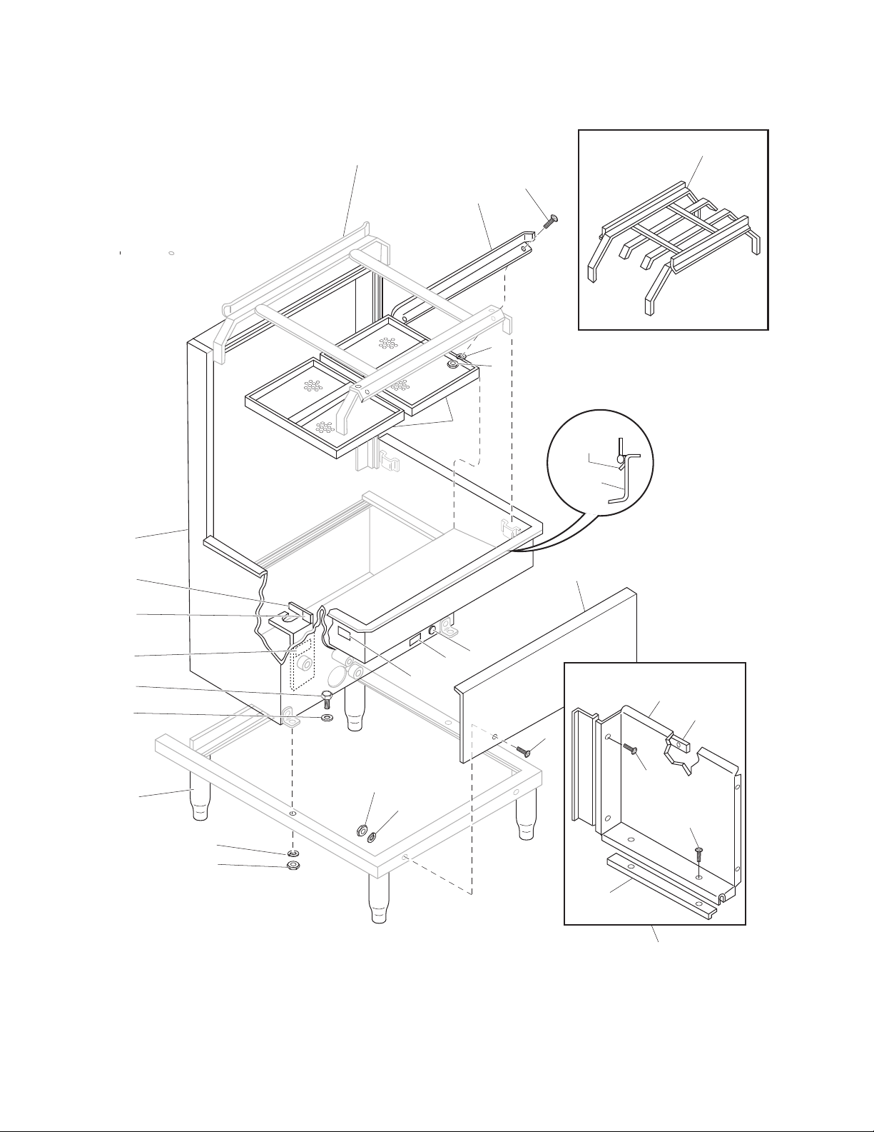
Figure 1. Base, Tank and Tracks
— 6 —
Page 7

Item No. Part No. Description Qty
1 W-3-13075 Track Assy 1
1A W-3-97352 Track Assy For 1/2 Racks (Std. in DD8) 1
2 W-2-13072 Interchangeable Track Guide 1
3 W-1-7850 Screw, Truss Hd. 1/4-20 × 1/2” Lg., S/S 4
4 W·1-7007 Lockwasher, 1/4”, S/S 4
5 W-1-7146 Nut, Hex 1/4-20, S/S 4
6 W-3-12555 Scrap Tray Assy 2
7 W-1-17810 Front Panel D8 1
7A W-2-95951 Front Panel DD8 1
8 W-0-14785 Nut, 3/8”, Plated 4
9 W-1-17245 Lockwasher, 3/8”, Plated 4
10 W-3-12512 Base Assy (Std. S/S) A/R
11 W-1-7522 Flat Washer, 3/8”, Plated 4
12 P-1-17230 Capscrew, 3/8-16 Hex Hd, Plated 4
13 W-3-17841 Tank Assy 1
14 W-1-5629 Rivet, 0.182 Dia. × 11/32 Lg., S/S 1
15 W-1-18649 Lever, Stand Pipe Guide 1
16 W-1-20629 Label, “Close” 1
Optional Items
17 W-2-13330 Splash Guard Component Assy (For corner model machines) A/R
18 W-3-l3322 Splash Guard 1
19 W-2-13324 Rear Mount, Splash Guard 1
20 W-1-13323 Bottom Mount, Splash Guard 1
21 W-1-13329 Hanging Strip, Splash Guard 1
22 W-1-8491 Screw, Truss Hd., 1/4-20 × 5/8”, S/S 4
23 W-1-95041 Warning Label Drain On This Side 1
— 7 —
Page 8
31
30
29
26
28
27
2
3
1
4
5
6
7
32
25
4
24
23
8
9
10
22
21
20
36
37
19
17
12
11
13
14
15
16
35
34
18
33
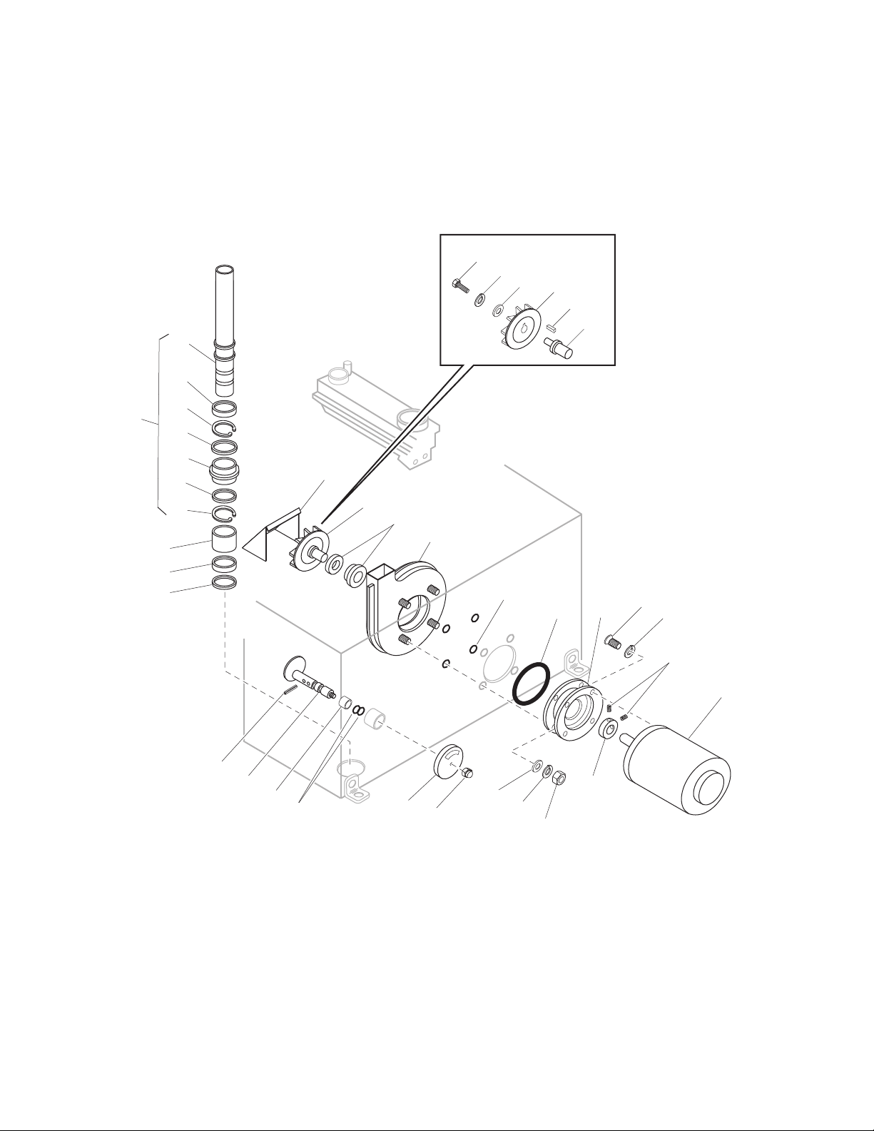
Figure 2. Stand Pipe, Pump and Drain
— 8 —
Page 9

Item No. Part No. Description Qty
1 W-1-17847 Stand Pipe Assy 1
2 W-1-17837 Stand Pipe 1
3 W-1-18641 Drain Strainer Retainer 1
4 W-0-18647 Retaining Ring 2
5 W-0-18645 Plug Ret, Washer (1-7/8" Dia.) 1
6 W-1-18427 Drain Plug 1
7 W-0-18646 Plug, Ret. Washer (1-1/2" Dia.) 1
8 W-1-18642 Strainer, Drain Seat 1
9 W-1-18644 Ring, Drain Seat 1
10 W-1-18648 Guide Ring, Stand Pipe 1
11 W-1-14802 Cam Shaft Assy 1
12 W-0-14895 Groove Pin, Cam Shaft 2
13 W-1-13905 Spacer, Cam Shaft 1
14 W-1-10340 “O” Ring 2
15 W-1-2924 Knob, Cam Shaft 1
16 W-0-18794 Stop Nut, Elastic 5/16-18 1
17 W-0-17798 Motor, 1.5 H.P., 115/230V, 1 Ph, 60 Hz (Used on 115 and 230 Single Phase machines) 1
17A W-0-8039 Motor, 1.5 H.P., 208/240, 480 3 Ph, 60 Hz (Used on 208/240/440/480V Three Phase machines) 1
17B W-0-81140 Motor, 1.5 H.P., 1151230V 1 Ph, 50 Hz (Export only) 1
17C W-0-81185 Motor, 1.5 H.P., 220/440V 3 Ph, 50 Hz (Export only) 1
18 W-1-17794 Collar, Impeller Shaft 1
19 W-1-7117 Setscrew, 5/16" × 3/8" 2
20 W-4-13087 Bracket, Pump Case and Motor – Used Before 1/98 1
20 74505 Motor Mounting. Bracket – Used After 1/98 1
21 W-0-13088 Quad Ring – Used Before 1/98 1
21 75004 “O” Ring – Used After 1/98 1
22 W-1-13446 “O” Ring 4
23 W-3-14849 Pump Case – Used Before 1/98 1
23 75761 Pump Weldment – Used After 1/98 1
24 W-2-2255 Pump Seal 1
25 W-2-17762 Impeller Assembly, consisting of: 1
26 W-2-95673 Impeller, 5" Dia. 1
27 W-2-95252 Impeller Shaft 1
28 M-1-1658 Key, 3/16 Sq. × 3/4" Lg. 1
29 1-5587 Washer, 11/32 × I.D., 1-1/4 O.D., S/S 1
30 W-1-7598 Lockwasher, 5/16 × 5.5 1
31 W-2-7621 Screw, Hex Hd. Mach., 5/16-18 × 3/4, S/S 1
32 77184 Pump Cover, Intake 1
33 W-0-14785 Nut, Hex 3/8-16 Plated 4
34 P-1-17245 Lockwasher, 3/8", Plated 4
35 W-1-8523 Seal Washer, 3/8" 4
36 P-1-17245 Screw, 3/8-16 × 1'' Lg. Hex Hd. Plated 4
37 W-1-7656 Lockwasher, 3/8", Plated 4
— 9 —
Page 10
1
763
20
21
22
19
23
18
24
27
26
25
2
302928
4
5
108
9
17
10
33
11
12
13
31
14
12
11
15
16
Figure 3. D8 Door and Lifting Mechanism
— 10 —
Page 11

Item No. Part No. Description Qty
1 W-3-12017 Door Handle Assy 1
2 W-0-16554 Bearing, Oilite Flange 2
3 W-1-8148 Screw, 3/8" × 3/4", S/S Hex Head Bolt 4
4 W-1-7524 Lockwasher, 3/8", S/S 4
5 W-1-5998 Nut, 3/8" Hex, S/S 4
6 W-1-14723 Support Bracket. dOOR Handle 2
7 W-0-14733 Bearing, Oilite Sleeve 2
8 W-0-12015 Retaining Ring, 3/8 2
9 W-1-12023 Linkage Assy, Door 2
10 W-1-7850 Screw, Truss Hd 1/4" × 1/2", S/S 14
11 W-1-7007 Lockwasher, S/S 14
12 W-1-7146 Nut, 1/4" Hex, S/S 14
13 97844 Nameplate, Door 1
14 W-2-13431 Bracket, Roller, R.H. 1
15 W-2-13430 Bracket, Roller, L.H. 1
16 W-1-14720 Roller, Door 2
17 W-3-14708 Door Hood Assy 1
18 W-1-14712 Plug, Bumper 4
19 W-0-17738 Groove Pin, 1/8" Dia. × 1/2" Lg. 4
20 W-1-12607 Screw, 1/4-20 × 1-1/2" Lg., S/S 4
21 W-1-12026 Stiener, Door Guide 2
22 W-1-12511 Guide, Door 2
23 W-1-7007 Lockwasher, 1/4", S/S 2
24 W-1-7146 Nut, 1/4-20, S/S 2
25 W-1-12987 Spring, Extension 2
26 W-0-14093 Eyebolt 2
27 W-0-14786 Nut, Hex 5/16-18 4
28 W-2-17739 Bracket Assy, Spring 2
29 W-0-16053 Cotter Pin 2
30 W-1-12836 Washer, Flat 2
31 W-1-95829 Splash Shield 2
D8 Tall- 76904 Handle Support —
— 76905 Handle —
— 11 —
Page 12

28
3
1
32
227
29
30
33
26
25
20
7
6
5
4
8 9 10
18
19
24
23
22
21
17
10
31
11
12
13
31
14
12
11
15
16
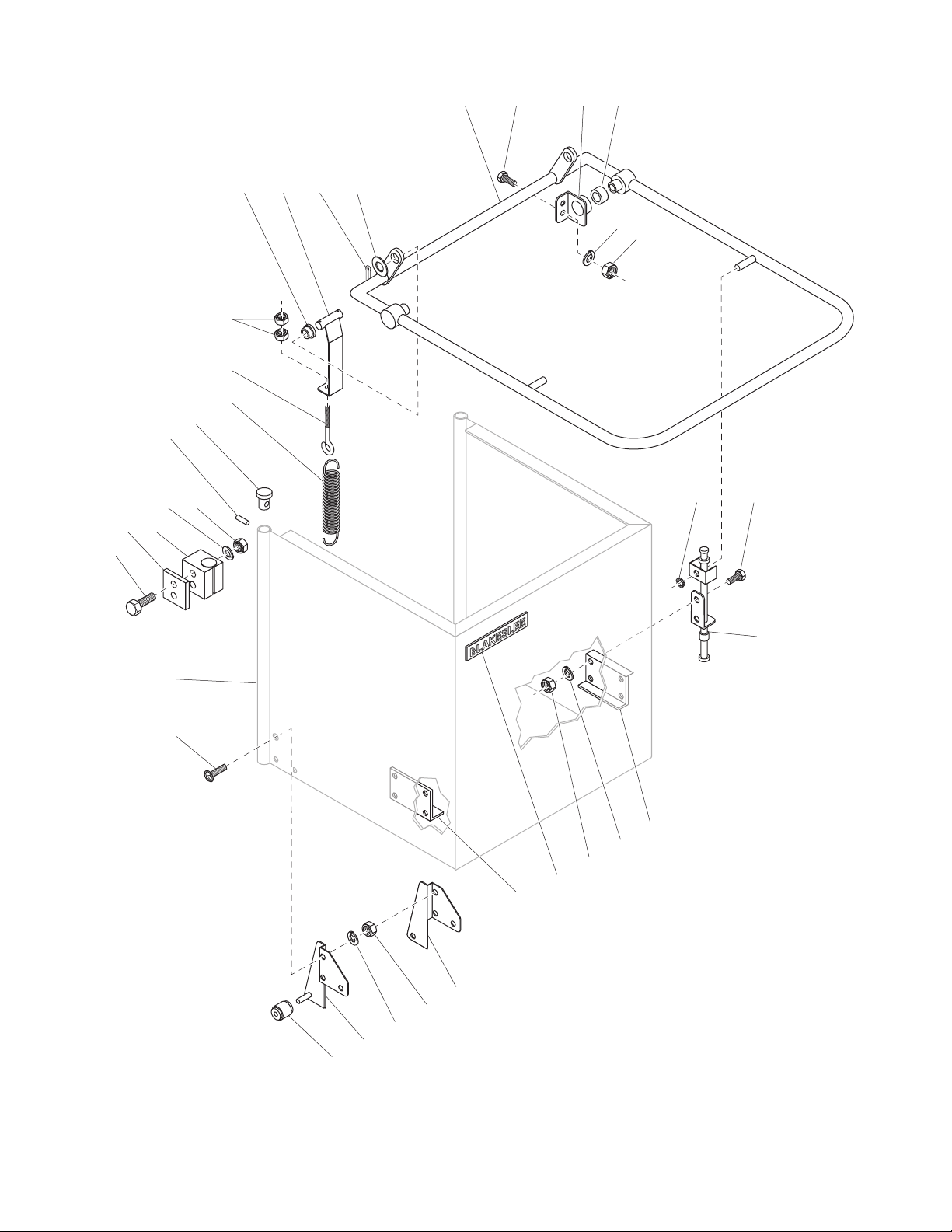
Figure 4. DD8 Door and Lifting Mechanism
— 12 —
Page 13

Item No. Part No. Description Qty
1 W-3-95944 Door Handle Assy 1
2 W-0-16554 Bearing, Oilite Flange 2
3 W-1-8148 Screw, 3/8" × 3/4", S/S Hex Head Bolt 4
4 W-1-7524 Lockwasher, 3/8", S/S 4
5 W-1-5998 Nut, Hex 3/8", S/S 4
6 W-1-14723 Support Bracket, Door Handle 2
7 W-0-14733 Bearing, Oilite Sleeve 2
8 W-0-12015 Retaining Ring, 3/8 2
9 W-1-12023 Linkage Assy, Door 2
10 W-1-7850 Screw, Truss Hd 1/4" × 1/2", S/S 14
11 W-1-7007 Lockwasher, S/S 14
12 7146 Nut, 1/4" Hex, S/S 14
13 97844 Nameplate, Door 1
14 W-2-13431 Bracket, Roller, R.H. 1
15 W-2-13430 Bracket, Roller, L.H. 1
16 W-1-14720 Roller, Door 2
17 W-3-97682 Door Hood Assy 1
18 W-1-14712 Plug, Bumper 4
19 W-0-17738 Groove Pin, 1/8" Dia. × 1/2" Lg. 4
20 W-1-12607 Screw, 1/4-20 × 1-1/2" Lg., S/S 4
21 W-1-12026 Stiener, Door Guide 2
22 W-1-12511 Guide, Door 2
23 W-1-7007 Lockwasher, 1/4", S/S 2
24 W-1-7146 Nut, 1/4-20, S/S 2
25 W-1-12987 Spring, Extension 2
26 W-0-14093 Eyebolt 2
27 W-0-14786 Nut, 5/16-18 Hex 4
28 W-2-95946 Bracket Assy, Spring 2
29 W-0-16053 Cotter Pin 2
30 W-1-12836 Washer, Flat 2
31 W-1-95829 Splash Shield 1
32 W-1-97687 Handle Rear Tie Weldment (Included with W-3-95944A) 1
33 W-2-95949 Spring Tie Bar 1
— 13 —
Page 14

2
7
1
5
4
6
4
RH
3
2
LH
8
10
Figure 5. Lower Rinse and Wash Arms
— 14 —
9
10
11
Page 15

Item No. Part No. Description Qty
1 W-1-72897 Rinse Arm Assy 1
2 W-1-2296 Rinse Plug 2
3 W-2-14513 Rinse Arm, Left 1
4 W-0-14516 Jam Nut, 1/2-20, S/S 2
5 W-1-14515 Revolving Rinse Head 1
6 W-2-14514 Rinse Arm, Right 1
7 W-1-73066 Rinse Flooding Nozzle, Lower 10
8 W-1-2731 Rinse Spindle Assy 1
9 W-3-72900 Wash Rotor Assy 1
10 W-1-20844 Bushing (Used after 1-1-78) 2
11 W-3-14853 Lower Manifold Assy 1
— 15 —
Page 16

7
6
3
5
4
8
2
1
9
10
11
12
13
New Style 1/1/2002
14
15
16
17
18
19
22
23
20
21
Figure 6. Upper Rinse and Fill Plumbing
— 16 —
Page 17

Item No. Part No. Description Qty
1 W-1-7026 Strainer, Line 1
1A W-1-13385 Screen Only, for Line Strainer A/R
2 W-1-7509 Nipple, Close 3/4" 2
3 W-1-12488 Solenoid Valve, 3/4", 115V 1
4 W-1-7508 Tee, Brass 3/4" × 3/4" × 1/4" 1
5 W-1-7942 Plug, 1/4" Brass 1
6 W-1-7033 Elbow, Street 3/4", 90° Brass 2
7 W-1-5913 Vacuum Breaker (See Note for Repair Kits) 1
8 7127 Tube Assy 1
9 W-0-7802 Thermometer 1
10 W-1-11065 Elbow, Reducer 3/4 - 1/2", 90° Brass 1
11 W-0-18441 Screw 2
12 W-1-7235 Microswitch 1
13 W-1-8067 Screw 2
14 W-1-16892 Bracket, Door Switch 1
15 W-1-12585 Gasket, Upper Rinse 1
16 W-1-7598 Lockwasher, S/S 2
17 W-1-12574 Nut, 5/16-18 Hex 2
18 W-0-14516 Jam Nut, Hex 1/2"-20 UNF, S/S 1
19 W-0-13365 Lockwasher 1
20 72897 Upper Rinse and Fill Line Assy 1
21 W-1-72896 Nozzle, Upper Spray 4
22 W-1-8709 Pipe Cap, 1/2", S/S 1
23 W-1-13433 Sleeve, Rinse Line 1
— 7917 Pressure Gauge (Optional) —
NOTE: When ordering Vacuum Breaker Repair Kits (W-1-12357 Sloan Valve, W-1-12351 Febco Valve or W-1-14835 Consolidated Valve),
please specify if your valve is manufactured by Sloan or Febco. You will nd the manufacturers name on the cap.
— 17 —
Page 18

1
2
3
4
5
9
7
6
7
8
Figure 7. Upper Manifold and Wash Arm
— 18 —
Page 19

Item No. Part No. Description Qty
1 W-1-12574 Nut. Hex 5/16-18, S/S 2
2 W-1-7598 Lockwasher, 5/16", S/S 2
3 W-1-7621 Screw, Hex Hd. 5/16-18 × 3/4", S/S 2
4 W-3-13081 Manifold Assy, Upper 1
5 W-1-17852 Spindle, Upper Wash 1
6 W-3-72900 Wash Rotor Assy 1
7 W-1-20844 Bushing (Used after 1-1-78) 2
8 W-1-2132 Nut Assy, Wash Arm 1
9 W-1-13559 Supply Pipe, Upper 1
— 19 —
Page 20

1
7
6
4
2
3
20
31
33
32
37
36
34
35
21
30
29
28
27
26
20
25
24
21
22
23
18
17
15
4
6
4
5
7
8
9
9A
10
11
13
19
12
14
16
COMPLETE ASSEMBLY
W-0-17966 NATURAL GAS
W-0-17967 L.P. GAS
Figure 8. Gas Burner Assembly (W-0-17966, Natural Gas) (W-0-17967, L.P. Gas)
— 20 —
Page 21

Item No. Part No. Description Qty
1 97007 Rear Support, Gas Burner 1
2 W-3-97706 Flue Assy, (Used on Production Machines Beginning 10-1-81) 1
3 W-4-4575 Burner Assy 1
4 W-1-7023 Lockwasher, 1/4" 10
5 M-1-3571 Screw, Hex Hd. 1/4-20 × 1/2" Lg. 2
6 W-1-7012 Nut, Hex 1/4-20 Cd Pi 10
7 W-1-7582 Screw, Ad Hd. 1/4-20 × 1/2" Lg 10
8 W-0-14185 Screw, Truss Hd. 3/8-16 × 1" Lg., S/S 4
9 W-1-17898 Cover, Heater Hole 1
9A W-1-2223 Gasket 2
10 W-1-17822 Mounting Plate, Gas Cont. Valve 1
11 W-1-7524 Lockwasher, 3/8", S/S 4
12 W-1-5998 Nut, Hex 3/8", S/S 4
13 W-1-8131 Screw, Round Hd. 10-32 × 1/2" Lg. 2
14 W-0-7705 Control Valve, (for L.P. Gas) 1
14A W-0-7642 Control Valve, (for Natural Gas) 1
15 W-1-8491 Screw, Hex Hd., 1/4-20 × 3/4" Lg. 2
16 W-0-14824 Nipple, 1/2 × 2" Lg. Black 1
17 W-1-7693 Elbow, Reducing 1/2 to 3/8" - 90° Black 1
18 W-1-7651 Tube, 1/4 × 17" Lg. Alum 1
19 W-2-17817 Front Support, Gas Burner 1
20 W-2-97708 Flue Cover, (Used on Production Machines Beginning 10-1-81) 1
21 W-0-13334 Connector, 1/2" Tube to 3/8" Pipe 2
22 W-1-7650 Thermocouple, 24" Lg. 1
23 W-0-16196 Pilot Burner, (For Natural Gas) 1
23A W-0-16197 Pilot Burner, (For L.P. Gas) 1
24 W-1-18291 Shield, Pilot 1
25 W-1-17961 Bracket, Pilot and Thermocouple 1
26 W-1-7285 Lockwasher, No. 10 4
27 W-1-10307 Screw, Round Hd. 10-32 × 3/8" Lg. 2
28 W-1-7637 Lockwasher, No. 8 Cd Pi 2
29 W-1-13063 Screw, Round Hd. 8-32 × 3/8" Lg. Cd Pi 2
30 W-0-13335 Tube, Alum. 1/2" × 7-1/2" Lg. 1
31 W-2-75809 Nozzle Assembly, Natural Gas 1
31A W-2-74094 Nozzle Assembly, L.P. Gas 1
32 W-0-70204 Tee, 3/8", Brass 1
33 W-0-71312 Plug, , 3/8", Brass 1
34 W-0-70395 Nipple, , 3/8", Brass 1
35 W-1-75807 Nozzle, Natural Gas 1
35A W-1-75809 Nozzle, L.P. Gas 1
36 75746 Mixer Head 1
37 W-1-7634 B. I. Close Nipple 1
— 21 —
Page 22

6
COMPLETE ASSEMBLY
W-3-13129
1
6
5
2
3
4
5
6
7
8
9
5
20
21
20
5
6
9
19
11
12
18
10
11
12
13
17
Figure 9. Steam Coil Assembly (W-3-13129)
— 22 —
14
15
14
16
Page 23

Item No. Part No. Description Qty
1 W-3-13090 Coil Assy 1
2 W-0-14185 Screw, Truss Hd. 3/8-16 × 1'', S/S 2
3 W-1-7524 Lockwasher, Split 3/8", S/S 2
4 W-1-5998 Nut, Hex 3/8-16, S/S 2
5 W-0-17702 Gasket, Copper/Asbestos for 1/2" Pipe 2
6 W-0-14267 Locknut, 1/2" N.P.S.L., Brass Pipe 4
7 W-0-13128 Coupling, 1/2", Black 1
8 W-0-20258 Nipple, 1/2 × 3-1/2" Lg., Black 1
9 W-1-10029 Elbow, 1/2" N.P.T. 90°, Black 2
10 W-1-14824 Nipple, 1/2 × 2" Lg., Black 1
11 W-1-11957 Union, 1/2", Black 2
12 W-0-13127 Nipple, 1/2" × 3" Lg., Black 2
13 W-0-7644 Reducer Elbow, 3/4 to 1/2" - 90°, Black 1
14 W-1-7634 Nipple, Close, 3/4" 2
15 W-1-12085 Solenoid Valve, 115V, 3/4" Steam 1
15a W-0-17390 Repair Kit, 3/4" Solenoid Valve, (Less Coil) A/R
15b W-0-17960 Coil Only, (Steam) A/R
16 W-1-7026 Strainer, 3/4" Line, Brass 1
16a W-1-13385 Strainer Screen, (United Brass) 1
16b W-0-17507 Line Strainer Cap, 3/4" 1
16c W-0-17506 Line Strainer “O” Ring, 3/4" 1
17 W-0-16877 Steam Trap, 1/2" N.P.T. 1
17a W-0-18135 Steam Trap, Rebuilding Kit 1
18 W-1-11947 Elbow, Street, 1/2", Black 1
19 W-0-13965 Nipple, 1/2" × 1-1/2", Black 1
20 W-1-13120 Mounting Plate, Steam Coil 2
21 W-1-2223 Gasket, Immersion Heater 2
— 23 —
Page 24

1
6
COMPLETE ASSEMBLY
W-3-12988
2
3
4
5
8
9
10
7
19
20
19
7
11
12
15
13
14
15
16
17
Figure 10. Steam Injector Assembly (W-3- 12988)
— 24 —
14
18
Page 25

Item No. Part No. Description Qty
1 W-1-12943 Half Nipple, 3/8 × 2", Brass 1
2 W-1-7027 Injector, Steam, Brass 1
3 W-1-7683 Nipple. Close, 1/4", Brass 1
4 W-1-12986 Coupling, Reducer 1/2" to 1/4", Brass 1
5 W-1-12944 Nipple, 1/2 × 2" N.P.S.L., Brass 1
6 W-0-14267 Locknut, 1/2" N.P.S.L., Brass Pipe 1
7 W-0-17702 Washer, Copper/Asbestos 2
8 W-0-14185 Screw, Truss Hd. 3/8-16 × 1", S/S 3
9 W-1-7524 Lockwasher, 3/8", S/S 3
10 W-1-5998 Nut, Hex 3/8-16 3
11 W-1-8453 Bushing, Reducer 3/4" to 1/2", Brass 1
12 W-1-7717 Check Valve, 3/4", Brass 1
13 W-1-12085 Solenoid Valve. 3/4" N.P.T., 115V (Steam) 1
13A W-0-17390 Repair Kit, 3/4" Solenoid Valve (Less Coil) A/R
13B W-0-17960 Coil Only (Steam) A/R
14 W-1-14825 Elbow, Street 3/4" × 90°, Black 2
15 W-1-7634 Nipple, Close 3/4", Black 2
16 W-1-11968 Union, 3/4", Black 1
17 W-0-14268 Nipple, 3/4" × 2", Black 1
18 W-1-7026 Strainer, 3/4" Line, Brass 1
18A W-1-13385 Strainer Screen (United Brass) 1
18B W-0-17507 Line Strainer Cap, 3/4" 1
18C W-0-17506 Line Strainer “O” Ring, 3/4" 1
19 W-1-12954 Mounting Plate, Injector 2
20 W-1-2223 Gasket, Immersion Heater 2
— 25 —
Page 26

1 2 3 4 5 6
5
4
3
3
4
2
1
HEATING ELEMENT ASSEMBLY
W-0-95377
Figure 11. Heating Element Assembly (W-0-95377)
— 26 —
Page 27

Electric Tank Heat for Front Mounted Heater
Item No. Part No. Description Qty
1 95377 Heating Element Assy (Consists of items 2, 3, 4, and 5) 1
2 18795 Heater, 2.5 kW 1
3 02223 Gasket, Heater 2
4 12024 Washer, Heater, S/S 2
5 12025 Locknut, 2" N.P.T. 1
Electric Tank Heat for Side Mounted Heater Serial No. Sux BBB
Item No. Part No. Description Qty
1 81201 Terminal Strip Assembly 1
2 77604 Junction Box Weldment 1
3 72688 Heater, 3 kW, 220V, 1p 1
3A 72688 Heater, 3 kW, 208/240V, 3p 1
3B 72689 Heater, 3 kW, 440/480V, 3p 1
` 4 7007 1/4" Lockwasher 2
5 7146 1/4" Nut 2
6 74602 High Limit Thermostat 1
Not Shown 77601 Junction Box Cover 1
— 27 —
Page 28

1 2 3 4 5 6,7
8 9
10
11 1224 23 22 20 21 19 13
17
16
Figure 12. Electrical Control Box for Machines Manufactured from 1/98 to 7/02
— 28 —
Page 29

Item No. Part No. Description Qty
1 17731 Front Cover 1
2 70155 Thermometer 1
3 17708 Label 1
4 16559 Power Light - Red 1
5 16560 Cycle Light - Amber 1
6 10765 Fuse Holder 1
7 10766 Fuse Slo-Blo, 1-6/10 1
8 07202 Push Button Switch 1
9 14479 Toggle Switch 1
10 05987 Screw, 10-24 × 1/2", S/S, Truss Head Mach. 6
11 17804 Control Box Gasket 1
12 17726 Control Box 1A/R
13 16782 Terminal Block A/R
*14 15799 Mounting Channel 2
*15 07999 Screw, 8-32 × 3/8" 1
16 74114 Ground Lug 1
17 17716 Chassis Panel 6
*18 17241 Screw, 10-32 × 3/8" 1
19 70192 Motor Contactor 1
20 71605 Overload Relay, 115V, 1p 1
20A 71603 Overload Relay, 230V, 1p 1
20B 71602 Overload Relay —
20C 71601 Overload Relay, 208/240V, 3p 1
20D 71600 Overload Relay, 440/480V, 3p 1
21 75581 Aux. Contact 2-Pole N/O, 3p 1
22 07209 Heat Contactor 1
23 14480 Timer 1
24 07768 Thermostat 1
**25 18132 Hinge 1
*26 07118 Screw, 1/4-20 × 1/2", S/S, Hex Head Mach. 4
*27 13063 R H.M.S., 8-32 × 3/8" 8
*28 07646 R H.M.S., 10-32 × 3/8" 2
*29 99705 Data Label 1
*30 74123 Warning Label 1
*31 07201 Transformer (440V only) 1
*32 15871 Nylon Clamp 2
Optional Equipment – Automatic Tank Fill for Machines Manufactured before 1/98
— 74235 Auto Fill Timer 1
— 07202 Fill and Start Push Button 1
— 74241 Switch Label 1
Optional Equipment – Automatic Cycle
— 73375 Solid State Timer 1
Optional Equipment – Thermal Cycle Extension
— 73952 Timer – Thermal Cycle Extension 1
— 75452 Solid State Relay 1
* Items not illustrated
— 29 —
Page 30

1 2 3 4 5 6, 7
POWER CYCLE
FUSE
1.6 AMP
W-2-17708
1312 26 21
28 25 27 24
START ON
8 9
OFF
3 4
2 5
6
1 MIN.
CYCLE TIME
10 11
2320 36 14
18 17
Figure 13. Electrical Control Box for Machines Manufactured After 9/05
with the Optional Multi-Cycle Timer Feature
— 30 —
Page 31

Item No. Part No. Description Qty
1 17731 Front Cover 1
2 70155 Thermometer 1
3 17708 Label 1
4 16559 Power Light - Red 1
5 16560 Cycle Light - Amber 1
6 10765 Fuse Holder 1
7 10766 Fuse Slo-Blo, 1-6/10 1
8 07202 Push Button Switch 1
9 14479 Toggle Switch 1
10 77954 Rheostat 6
11 05987 Screw, 10-24 × 1/2", S/S, Truss Head Mach. —
12 17804 Control Box Gasket 1
13 17726 Control Box 1A/R
14 16782 Terminal Block A/R
*15 15799 Mounting Channel 2
*16 07999 Screw, 8-32 × 3/8" 1
17 74114 Ground Lug 1
18 17716 Chassis Panel 6
*19 17241 Screw, 10-32 × 3/8" 1
20 70192 Motor Contactor 1
21 71605 Overload Relay, 115V, 1p 1
21A 71603 Overload Relay, 230V, 1p 1
21B 71601 Overload Relay, 208/240V, 3p 1
21C 71600 Overload Relay, 440/480V, 3p 1
*22 75581 Aux. Contact 2-Pole N/O, 3p 1
23 07209 Heat Contactor 1
24 74235 Timer TM1 - Auto-Fill 1
25 77953 Timer TM2 - Wash Cycle .49 to 10 min. 1
26 77952 Timer TM3 - Rinse Cycle 11 sec. 1
27 75584 Relay 1
28 07768 Thermostat 1
*29 18132 Hinge 1
*30 07118 Screw, 1/4-20 × 1/2", S/S, Hex Head Mach. 4
*31 13063 R.H.M.S., 8-32 × 3/8" 8
*32 07646 R.H.M.S., 10-32 × 3/8" 2
*33 17708 Name Plate 1
*34 99705 Data Label 1
*35 74123 Warning Label 1
36 07201 Transformer 1
*37 15871 Nylon Clamp 2
* Items not illustrated
— 31 —
Page 32

1 2 3 4 5 6,7
8 9
10
11 1224 23 22 20 21 19 13
33
1734
31
16
Figure 14. Electrical Control Box for Machines Manufactured After 5/07
— 32 —
Page 33

Item No. Part No. Description Qty
1 17731 Front Cover 1
2 70155 Thermometer 1
3 17708 Label 1
4 16559 Power Light - Red 1
5 16560 Cycle Light - Amber 1
6 10765 Fuse Holder 1
7 10766 Fuse Slo-Blo, 1-6/10 1
8 07202 Push Button Switch 1
9 14479 Toggle Switch 1
10 05987 Screw, 10-24 × 1/2", S/S, Truss Head Mach. 6
11 17804 Control Box Gasket 1
12 17726 Control Box 1A/R
13 16782 Terminal Block A/R
*14 15799 Mounting Channel 2
*15 07999 Screw, 8-32 × 3/8" 1
16 74114 Ground Lug 1
17 17716 Chassis Panel 6
*18 17241 Screw, 10-32 × 3/8" 1
19 70192 Motor Contactor 1
20 71605 Overload Relay, 115V, 1p 1
20A 71603 Overload Relay, 230V, 1p 1
20B 71602 Overload Relay —
20C 71601 Overload Relay, 208/240V, 3p 1
20D 71600 Overload Relay, 440/480V, 3p 1
21 75581 Aux. Contact 2-Pole N/O, 3p 1
22 07209 Heat Contactor 1
23 14480 Timer 1
24 07768 Thermostat 1
**25 18132 Hinge 1
*26 07118 Screw, 1/4-20 × 1/2", S/S, Hex Head Mach. 4
*27 13063 R H.M.S., 8-32 × 3/8" 8
*28 07646 R H.M.S., 10-32 × 3/8" 2
*29 99705 Data Label 1
*30 74123 Warning Label 1
31 07201 Transformer 1
*32 15871 Nylon Clamp 2
Opt 33 74235 Auto Fill Timer 1
34 75584 Relay 1
* Items not illustrated
— 33 —
Page 34

8 7 6 4 5 4 312
2
HIGH WATER
LEVEL
11
9
LOW WATER
LEVEL
10 9 1
COMPLETE ASSEMBLY
W-3-20453
Figure 15. Automatic Tank Fill “Type C”
— 34 —
Page 35

Item No. Part No. Description Qty
1 W-1-18865 Float Switch, Liquid 3 Amp.
2 W-0-20461 Elbow, Street 1/4", S/S 1
3 W-1-20449 Bushing, Extension 1
4 W-0-18921 Washer, Flat, S/S 2
5 W-0-18866 “O“ Ring, 1/2" O.D.
6 W-0-18928 Locknut, 1/4" Brass 1
7 W-1-7684 Bushing, Reducer 1/2" to 1/4" 1
8 W-1-12830 Elbow, Pulling – 1/2" – 90° 1
9 W-1-7680 Connector, 3/8 – 90° Liquid Tight Connector 2
10 W-0-20466 Conduit, Liquid Tight 3/8" × 6-1/2" Lg. A/R
11 W-1-7587 Gasket Assy., 1/2" 1
12 W-1-8360 Nut, Drive 1/2" 1
— 35 —
Page 36

21
19
18
20
17
16
1
2
4
3
2
1
5
8
9
8
12
13
7
10
11
14
11
15
6
23
22
Figure 16. Machine Mounted Final Rinse Booster (Single D8 Only)
— 36 —
Page 37

Item No. Part No. Description Qty
1 W-1-8360 Locknut, Tiger Grip 2
2 W-1-8587 Gasket, 1/2" 2
3 W-1-7817 Connector, Str. 1/2" Liquid Tight 1
4 See note Liquid Tight Conduit, 1/2" × 12" Lg. 1
5 W-1-8836 Elbow, 45°, 1/2" Liquid Tight 1
6 72737 Wiring Diagram, Abbrev. 1
7 99705 Data Label 4
8 W-1-8000 Screw, 6-32 × 1/4" Lg. Round Hd. 1
9 W-1-16221 Bracket, Thermostat Mtg. 1
10 W-0-7768 Thermostat, w/Capillary 6
11 W-1-8131 Screw, 10-32 × 1/2" Lg. Round Hd. 1
12 W-1-7210 Contactor, 60 Amp. 3 Pole 4
13 — Heater, Immersion 2.5 kW, See Chart Below 1
14 W-1-8004 Screw, 6-32 × 1/2" Lg. Round Hd. 1
15 74602 Switch, 250" High Limit Cut-O 1
16 72627 Box, Booster Element 1
17 20912 Gasket Assy, Booster 2
18 72644 Tank Assy, Booster Element 5 Hole (Use 72644 for 3 Hole) 1
19 W-1-7012 Nut, 1/4-20 2
20 W-1-7023 Lockwasher, 1/4" 2
21 M-1-3571 Screw, Hex Hd. 1/4-20 × 1/2" Lg. 2
22 71612 Screw, 10-32 × 1/2" Lg. Round Hd. 4
23 72574 Box Cover 1
*24 16782 Terminal Block 1
NOTE:
— W-1-7590 Liquid Tight Conduit, 1/2" (order, feet required) —
* Items not illustrated
Booster Immersion Heater Chart
Heater Part No. Voltage Phase kW Amps
72635 208/240 1 12.0 58
72635 208/240 3 12.0 34
72634 440/480 3 12.0 16
72636 208/2110 1 15.0 72
72636 208/240 3 15.0 42
72460 440/480 3 15.0 20
72688 208/240 1 9.0 42
72688 208/240 3 9.0 26
72689 440/480 3 9.0 13
— 37 —
Page 38

1
2
4
3
5
14
15
18, 19, 21
18, 19, 21
21
6
17
10
16
7
10
13
11
8
3
10
Figure 17. Machine Mounted Booster Plumbing and Electrical (Single D8 Only)
— 38 —
12
9
Page 39

Item No. Part No. Description Qty
1 13607 Nipple, 3/4" × 2" Lg. Brass 1
2 W-1-13608 Union, 3/4" Brass 1
3 W-1-8219 Elbow, 90° Brass 2
4 7514 Nipple, 3/4" × 2-1/2" Lg. Brass 1
5 73789 Pipe, Brass 3/4" × 39-1/2" Lg. 1
6 W-1-8217 Union Elbow, 3/4" × 90° Brass 1
7 W-1-8219 Elbow, 3/4" × 90° N.P.T. Brass 1
8 W-1-18263 Nipple, 3/4" × 8" Lg. – Brass 1
9 W-1-12488 Solenoid Valve, 3/4", 120V 1
10 W-0-14250 Nipple, 3/4" Close 4
11 W-1-7508 Tee, 3/4" × 3/4" × 1/4" 1
12 W-1-7683 Nipple, Close 1/4 N.P.T. × 7/8" Lg. 1
13 W-1-4082 Gauge Cock, 1/4 N.P.T. 1
14 W-1-7917 Gauge, Pressure A/R
14A W-0-18194 Gauge, Pressure, Chrome Plated (Optional) A/R
15 W-1-7116 Plug, 1/4" N.P.T. Pipe (Used In Place of Pressure Gauge) A/R
16 W-1-7916 Regulator, Pressure 3/4" 1
17 W-1-7026 Strainer, 3/4" Brass 1
18 W-1-7581 Gasket Assy., 1/2" 2
19 W-1-8360 Locknut, Tiger Grip 2
20 See Note Conduit, 3/8 × 21" Lg. Liquid Tight A/R
21 W-1-7580 Elbow, 3/8" × 90° Liquid Tight 2
NOTE:
— W-1-7589 Liquid Tight Conduit, 3/8" (Order Feet Required —
— 07918 Relief Valve —
— 39 —
Page 40

Notes
— 40 —
Page 41

USA
Date of Installation ________________________________
Serial No. Model No.
_____________________ _____________________
Limited Warranty
Your new Blakeslee dishwashing machine is warranted for one year from date of installation shown above
against defective materials and workmanship. If any defects are found within the warranty period, parts, and
labor involved with their replacement will be covered free of charge. Service must be performed by a Blakeslee
authorized service agency. All labor to be performed during regular working hours. Overtime premium will be
charged to the customer. All warranty parts are shipped by surface transportation. If other means of transportation is requested the customer is required to pay the premium. This warranty does not apply to damages
resulting from errors in installation on the part of other contractors, nor does it apply to machines which have
been subject to accident, misuse, or abuse. It is understood that Blakeslee’s warranty obligation with respect
to machines located outside of the United States and Canada or located in the state of Alaska is limited to
the furnishing of replacement parts only. In the state of Hawaii, repair labor is provided free of charge; travel
time and expenses paid by the customer. On the island of Oahu, repair labor, travel time and expenses are
provided free of charge. This is the entire and only warranty of Blakeslee. We neither assume nor authorize
anyone else to assume for us any other obligation or liability in connection with Blakeslee Machines.
In no case can this warranty exceed eighteen (18) months from the date of shipment from our plant at Addison, Illinois.
Items NOT Covered Under Warranty:
1. Lighting of Gas Pilots
At the time of installation the gas pilots and burners should
be adjusted. Continued failures of pilot lights would
indicate dirty gas lines, improper original adjustment or
intermittent drafts blowing out the ume.
2. Replacing Fuses or resetting Overloads
Replacing a blown fuse or resetting an open overload
breaker is a very simple procedure and is the owner’s
responsibility. If the machine continues to blow fuses
or open the overload breaker, contact your nearest
authorized Blakeslee Service Center.
3. Adjusting Tank Heats
Heat adjustments are covered in the INSTALLATION &
OPERATION manual and must be adjusted depending
upon desired results.
4. Proper Loading of Dishes
It is important that the machine owner’s personnel
observe the instructions outlined in the INSTALLATION
& OPERATION manual.
5. Cleaning Drain Valves
Foreign articles lodged in the drain valve seat should be
removed as a part of the normal daily cleaning.
6. Cleaning Rinse or Wash Nozzles and Line Strainers
Keeping a dishwasher clean and removing obstructions
from the nozzles and line strainers will be a periodic
function of the machine owner’s personnel. The cleaning
periods will vary depending upon impurities in the water
supply and cleanliness of the washing operation.
7. Final Rinse Water
Most frequent of all complaints in any dishwashing
machine is that of poor nal rinse. It is the responsibility
of the owner to provide 180to 195 degree (plus) water at
15-25 lb. ow pressure through clean unobstructed water
lines. If the machine has a factory equipped nal rinse
water booster, the owner must supply the booster with
a minimum of 140 degree temperature water.
8. Electric Boosters and Garbage Disposals
Although these units may have been purchased with
the machine, they are warranted by the individual
manufacturer. Consult the nearest factory authorized
representatives for these particular items.
— 41 —
Page 42

1228 Capitol Drive
Addison, IL 60101
Phone: 630-532-5021
Fax: 630-532-5020
www.blakesleeinc.com
service@blakesleeinc.com
— 42 —
 Loading...