

Page 1
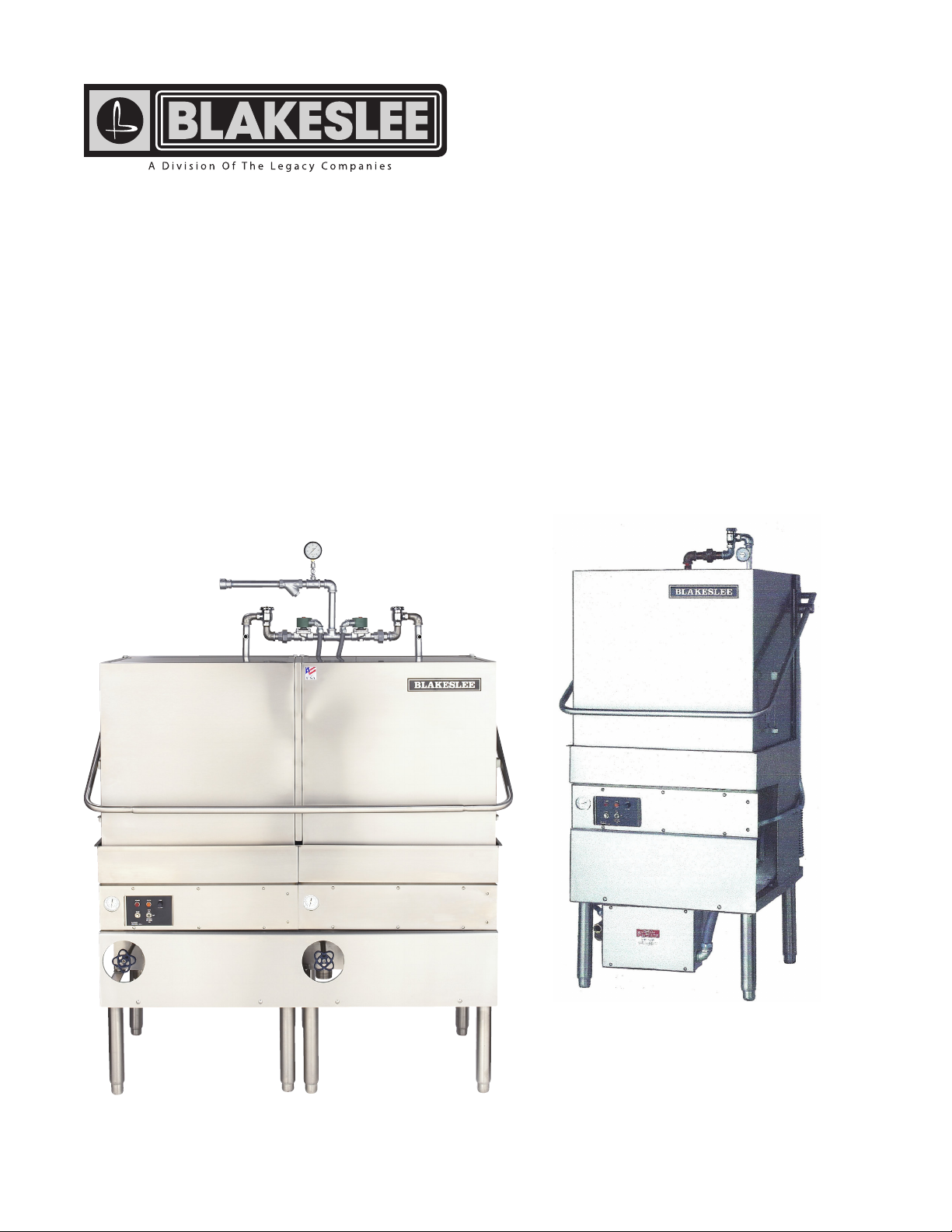
D-8 & DD-8
DISHWASHERS
INSTALLATION &
OPERATION
(01-13)
Page 2
ELECTRICAL WARNINGS
THIS MANUAL HAS BEEN PREPARED FOR PERSONNEL QUALIFIED TO INSTALL
ELECTRICAL EQUIPMENT, WHO SHOULD PERFORM THE INITIAL FIELD STARTUP AND
ADJUSTMENTS OF THE EQUIPMENT COVERED BY THIS MANUAL.
READ THIS MANUAL THOROUGHLY BEFORE OPERATING, INSTALLING OR
PERFORMING MAINTENANCE ON THE EQUIPMENT.
WARNING: Failure to follow all the instructions in this manual can
cause property damage, injury or death.
WARNING: Improper installation, adjustment, alteration, service or
maintenance can cause property damage, injury or death.
WARNING: Electrical connections should be performed only by a certied
professional.
WARNING: Electrical and grounding connections must comply with the
applicable portions of the National Electric Code and/or all local electric codes.
Failure to comply with this procedure can cause property damage, injury or death.
WARNING: Before connecting the unit to the electrical supply, verify that
the electrical and grounding connections comply with the applicable portions of
the National Electric Code and/or all local electrical codes. Failure to comply with
this procedure can cause property damage, injury or death.
WARNING: Before connecting the unit to the electrical supply, verify that
the electrical connection agrees with the specications on the data plate. Failure to
comply with this procedure can cause property damage, injury or death.
WARNING: UL73 Grounding Instructions: This appliance must be connected
to a grounded, metal, permanent wiring system; or an equipment-grounding
conductor must be run with the circuit conductors and be connected to the
equipment-grounding terminal or lead on the appliance. Failure to comply with this
procedure can cause property damage, injury or death.
WARNING: Appliances equipped with a exible electric supply cord are
provided with a three-prong grounding plug. It is imperative that this plug be
connected into a properly grounded three-prong receptacle. Failure to comply with
this procedure can cause property damage, injury or death.
WARNING: If the receptacle is not the proper grounding type, contact an
electrician. Do not remove the grounding prong from the plug. Failure to comply
with this procedure can cause property damage, injury or death.
— 2 —
Page 3

WARNING: Before performing any service that involves electrical
connection or disconnection and/or exposure to electrical components, always
perform the Electrical LOCKOUT/TAGOUT Procedure. Disconnect all circuits. Failure
to comply with this procedure can cause property damage, injury or death.
WARNING: Before removing any sheet metal panels, always perform the
Electrical LOCKOUT/TAGOUT Procedure. Be sure all circuits are disconnected.
Failure to comply with this procedure can cause property damage, injury or death.
WARNING: Do not operate this equipment without properly placing and
securing all covers and access panels. Failure to comply with this procedure can
cause property damage, injury or death.
WARNING: Do not use or store gasoline or other ammable vapors or
liquids in the vicinity of this or any other appliance. Failure to comply can cause
property damage, injury or death.
WARNING: In the event of a power failure, do not attempt to operate this
appliance. Failure to comply can cause property damage, injury or death.
ELECTRICAL LOCKOUT/TAGOUT PROCEDURE
WARNING
Before performing any service that involves electrical
connection or disconnection and/or exposure to
electrical components, always follow the Electrical
LOCKOUT/TAGOUT Procedure. Disconnect all circuits.
Failure to comply with this procedure can cause
property damage, injury or death.
The Electrical LOCKOUT/TAGOUT Procedure is used to
protect personnel working on an electrical appliance.
Before performing any maintenance or service that
requires exposure to electrical components, follow these
steps:
1. In electrical box, place appliance circuit breaker into
OFF position.
2. Place a lock or other device on electrical box cover
to prevent someone from placing circuit breaker ON.
3. Place a tag on electrical box cover to indicate that
appliance has been disconnected for service and
power should not be restored until tag is removed
by maintenance personnel.
4. Disconnect appliance power cord from electrical
outlet.
5. Place a tag on the cord to indicate that unit has
been disconnected for service and power should
not be restored until tag is removed by maintenance
personnel.
— 3 —
Page 4

TABLE OF CONTENTS
GENERAL DESCRIPTION ..............................................................................................................................................................................................................5
Model D-8 ................................................................................................................................................................................................................................5
Model DD-8.............................................................................................................................................................................................................................5
Door Safety Switch ...............................................................................................................................................................................................................5
Pump Motor ............................................................................................................................................................................................................................5
Control Circuit ........................................................................................................................................................................................................................5
Vacuum Breaker ....................................................................................................................................................................................................................5
Heaters......................................................................................................................................................................................................................................5
Automatic Wash Tank Fill ...................................................................................................................................................................................................5
Final Rinse Boosters (Optional) ........................................................................................................................................................................................5
Heat and Voltage Field Changeover ..............................................................................................................................................................................5
INSTALLATION ..................................................................................................................................................................................................................................6
Visual Inspection ...................................................................................................................................................................................................................6
Unpacking the Dishwasher ...............................................................................................................................................................................................6
Leveling the Dishwasher ....................................................................................................................................................................................................6
Plumbing the Dishwasher .................................................................................................................................................................................................6
Dish Tables ..............................................................................................................................................................................................................................6
Electrical Connections ........................................................................................................................................................................................................7
Pump Motor Rotation .........................................................................................................................................................................................................8
Fill/Rinse ...................................................................................................................................................................................................................................8
Drains ........................................................................................................................................................................................................................................8
Electric Heater ........................................................................................................................................................................................................................9
Gas Heater ...............................................................................................................................................................................................................................9
Pilot Lighting ....................................................................................................................................................................................................................... 11
Pilot Flame Adjustment ................................................................................................................................................................................................... 12
Gas Vents............................................................................................................................................................................................................................... 12
Steam Injected Heaters ................................................................................................................................................................................................... 12
Steam Coil Heater .............................................................................................................................................................................................................. 12
Electrical Detergent and Rinse Additive Injector Connections ......................................................................................................................... 12
OPERATION ....................................................................................................................................................................................................................................14
Preparing the Dishwasher for Use ............................................................................................................................................................................... 14
Automatic Tank Fill (Standard) ...................................................................................................................................................................................... 14
Wash Cycle Selector .......................................................................................................................................................................................................... 14
Automatic Start (Optional) ............................................................................................................................................................................................. 15
Manual Start (Standard) .................................................................................................................................................................................................. 15
Tank Selection (Optional on DD-8 only) .................................................................................................................................................................... 15
Soiled Dishtable Operation ............................................................................................................................................................................................ 15
Loading the Dishwasher ................................................................................................................................................................................................. 15
Operating the Dishwasher ............................................................................................................................................................................................. 16
Shutdown and Cleaning ................................................................................................................................................................................................. 16
Maintenance ................................................................................................................................................................................................................................. 18
Motor...................................................................................................................................................................................................................................... 18
Pump ...................................................................................................................................................................................................................................... 18
Doors/Hood ......................................................................................................................................................................................................................... 18
Line Strainers ....................................................................................................................................................................................................................... 18
Wash Arms............................................................................................................................................................................................................................18
Final Rinse Arms and Nozzles ........................................................................................................................................................................................ 18
Pump Motor Overload Protection ............................................................................................................................................................................... 19
Water Treatment................................................................................................................................................................................................................. 19
Troubleshooting.................................................................................................................................................................................................................20
SCHEMATIC .................................................................................................................................................................................................................................... 22
WIRING DIAGRAM ....................................................................................................................................................................................................................... 24
WARRANTY .................................................................................................................................................................................................................................... 26
— 4 —
Page 5

GENERAL DESCRIPTION
Model D-8
The Model D-8 door-type commercial dishwasher has a
three-sided door or hood that is spring counterbalanced
and opens as one unit to provide access to the machine. The
machine can be easily modied from a straight- through to
a corner unit by simply moving one track rail. If the unit is
to be used in a corner, the right side should be positioned
toward the wall to allow access to the controls.
Model DD-8
The Model DD-8 door-type commercial dishwasher has a
three-sided door or hood that is spring counterbalanced
and opens as one unit to provide access to the machine.
The unit has two wash tanks and can wash two dish racks
at a time. The Model DD-8 can be specied as a straightthrough or corner unit when ordering. The side to be
used in the corner must be designated so the controls
are accessible.
Door Safety Switch
All models are equipped with a door safety switch. The
machine will not operate when the door is open. If the
door is accidently opened during a cycle, the machine will
stop operating. Some models may be equipped with an
optional door safety lock which prevents the door from
opening during a cycle.
On manual start units, the door must be closed and the
operator must press the start button to initiate a cycle.
On machines equipped with the optional automatic
start feature, the operator need only close the door to
start a cycle.
Control Circuit
All units are supplied with a 110 VAC control circuit.
Vacuum Breaker
The ll line has a vacuum breaker installed in it to prevent
any backow of water into the fresh water supply line. If
a negative pressure develops in the supply line, the loss
of pressure permits a check valve inside the breaker to
drop, sealing the orice. At the same time, a vent opens
admitting air to the system to break the vacuum.
Heaters
Wash tank water is heated by electricity, steam coil, steam
injection or gas. Electrically heated machines are available
in 208, 240, 440, or 480 VAC only.
Automatic Wash Tank Fill
All machines are supplied with automatic wash tank ll.
Final Rinse Boosters (Optional)
Machines can be equipped with an optional built-in
electric booster, remote mounted booster or remote
mounted steam booster. These boosters are designed
to raise the rinse water temperature from 140°F to
180F°-185°F.
Heat and Voltage Field Changeover
Pump Motor
The unit is equipped with a 1½ HP motor. Model D-8 has
one motor; Model DD-8 has two motors.
When changing either to or from single- to three-phase
electrical power, the wash pump motor must be changed.
The motor overload relays must also be changed. See
parts description in the separate Illustrated Parts List and
wiring diagram.
When changing from 115 volts to 208, 230, 440 or 480 VACs,
single- or three-phase, a transformer must be added. The
motor overload relays must also be changed.
— 5 —
Page 6
INSTALLATION
Visual Inspection
Before installing the unit, inspect the shipping container
and machine for damage. A damaged container may
indicate there is damage to the machine. If there is
damage to both the container and machine, do not throw
away the container. The dishwasher has been inspected
and packed at the factory and is expected to arrive in
an undamaged condition. However, rough handling by
carriers or others may result in damage to the unit while
in transit. If such a situation occurs, do not return the unit
to Blakeslee; instead, contact the carrier and ask them to
send a representative to the site to inspect the damage
to the unit and to complete an inspection report. You
must contact the carrier within 48 hours of receiving the
machine. Also, contact the dealer where you purchased
the unit.
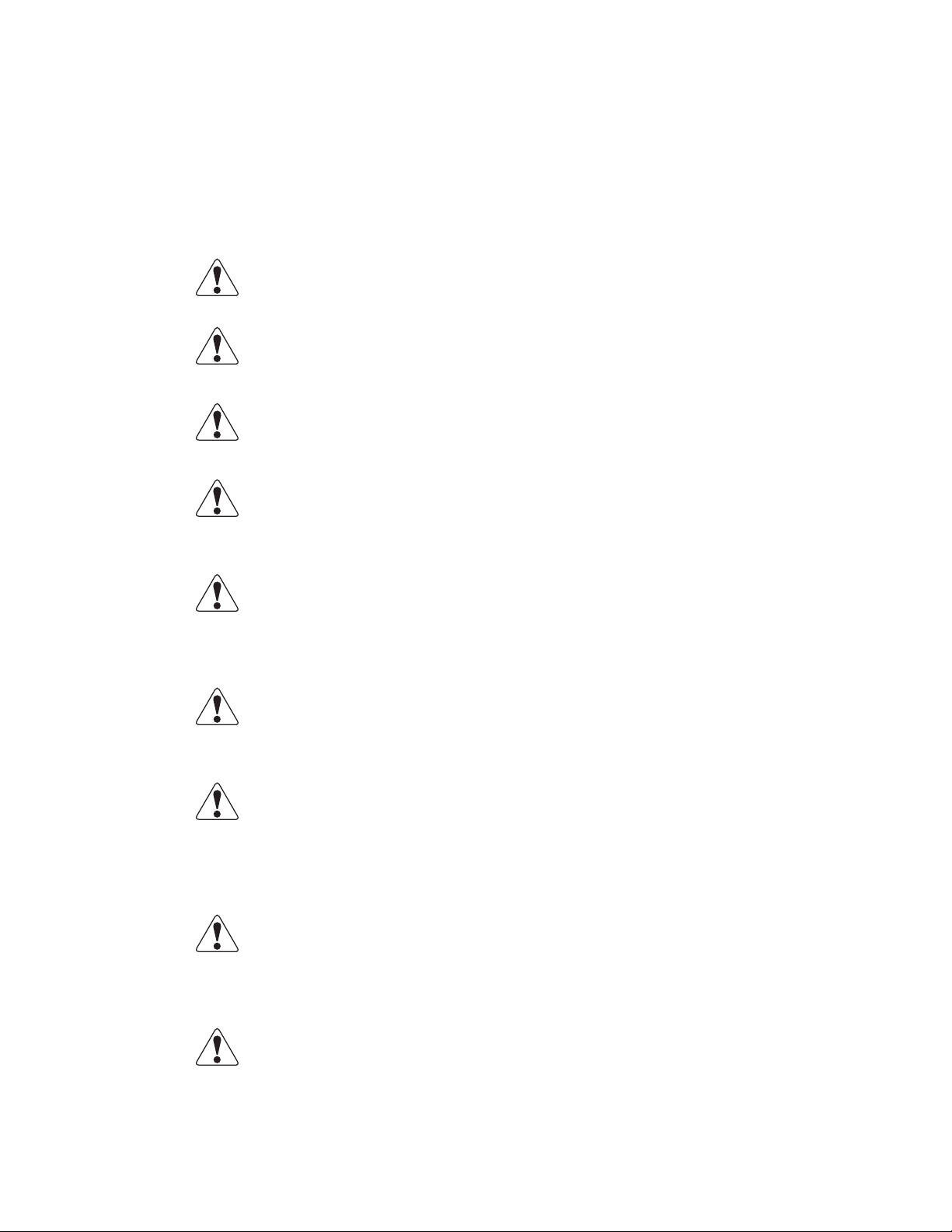
Unpacking the Dishwasher
Excessive gap
on left:
Raise left front
leg and door will
shift to the left
Excessive gap
on right:
Raise right front
leg and door will
shift to the right.
34-1/4" ± 3/4"
Leveling the Dishwasher
Once the machine has been removed from the container,
make sure that there are no parts missing from the
machine. This may not be obvious at rst. If an item is
missing, contact Blakeslee immediately to have the missing
item shipped to you.
Leveling the Dishwasher
The dishwasher must be level to operate correctly. This
allows the hood to open and close properly and ensures
the best results while washing. The unit comes with
adjustable bullet feet, which can be turned using a pair of
channel locks or by hand if the unit can be raised safely.
Ensure that the unit is level from side to side and from front
to back before making any service connections. Minor
adjustments to the feet may be necessary to eliminate
any door gaps once the unit has been leveled.
Plumbing the Dishwasher
All plumbing connections must comply with all applicable
local, state, and national plumbing codes. The installing
plumber must ush the incoming water line thoroughly
prior to connecting it to the dishwasher. Any valves that
are fouled as a result of foreign matter left in the water
line, and any expenses resulting from this fouling, are not
covered under the manufacturer’s warranty.
Various connections are labeled “180° Water”, “Steam”,
“Gas”, etc. Only connect the corresponding service to
these connections.
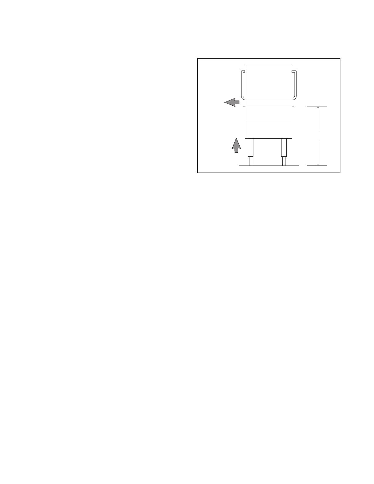
Dish Tables
Dish tables must be lipped into and slope slightly toward
the dishwasher. Use silicone sealant between the dish
table and the dishwasher. Secure with stainless steel
truss head screws.
— 6 —
Page 7
Washer
Hood
Gap
Table
Truss head screws,
lockwashers and nuts
S/S
Electrical Connections
WARNING
Before performing any service that involves electrical
connection or disconnection and/or exposure to
electrical components, always perform the Electrical
LOCKOUT/TAGOUT Procedure. Disconnect all circuits.
Failure to comply with this procedure can cause
property damage, injury or death.
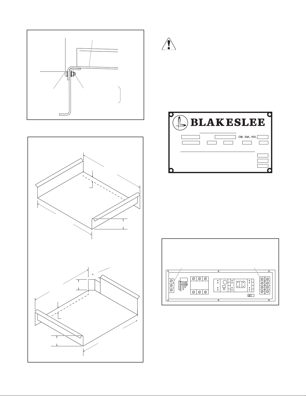
Refer to the unit’s data plate before making any
connections.
Attach Table to Tank
DISHTABLE DIMENSION INFORMATION
1"
22" MIN.
LEFT SIDE TABLE
Right side table (not shown) –
dimensions are same but reversed
6"
23-3/8"
4" MAX.
Notch for
Hood Handle
POWER REQUIREMENT
MOD.
VOLTS
BRANCH CIRCUIT PROTECTION REQUIREMENT
SUPPLY CIRCUIT CONDUCTORS (MINIMUM AMPACITY)
W-2-20878
SER. NO.
PH. HZ. AMP. H P.
CIRCUIT-BREAKERS (MAZIMUM AMPACITY)
TIME-DELAY FUSES (MAZIMUM AMPACITY)
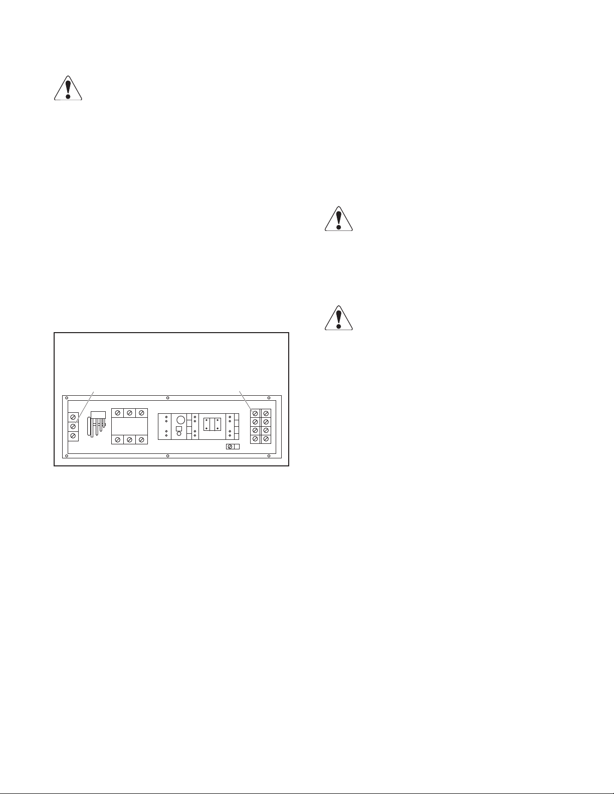
Any connections must correspond to the information
specied on the data plate. A fused disconnect switch
or circuit breaker (not supplied) MUST be installed in
the electrical supply line for the dishwasher. This service
connection must meet all local and national electrical code
requirements. All connections are made at one common
location in the control box. The control box cover is hinged
and can be opened by removing six (6) ¼ -20 screws and
swinging the cover to the right.
Thermostat –
Turn screw clockwise to
increase temperature;
Turn counterclockwise to
decrease temperature
Incoming
power
connection
4" MAX.
25-3/4"
1"
4" MAX.
FRONT TABLE
(Corner installation only)
26-3/4" MIN.
Thermostat & Power Connection Locations
Note: If the unit has the optional electrical booster,
refer to section on Boosters for separate electrical
connection information.
— 7 —
Page 8
Pump Motor Rotation
WARNING
Before performing any service that involves electrical
connection or disconnection and/or exposure to
electrical components, always perform the Electrical
LOCKOUT/TAGOUT Procedure. Disconnect all circuits.
Failure to comply with this procedure can cause
property damage, injury or death.
The pump motor(s) must rotate in a clockwise direction
as viewed from the front of the dishwasher. An arrow
on the side of the pump motor(s) indicates the correct
motor direction.
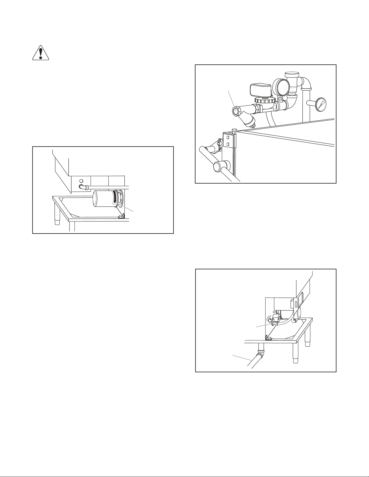
Connect a ¾" pipe to the line strainer.
For a piping run greater than 20 ft, increase the pipe size
to insure proper ow pressure at the dishwasher.
Line Strainer
Line Strainer
Motor rotation
arrow
Pump Motor Rotation
This rotation was checked at the factory but must be
rechecked before putting the dishwasher into service.
Note: There may be more than one pump motor
depending on the model.
Fill/Rinse
Final Rinse water is used to ll the dishwasher’s wash
tank(s). The water supply must have a water temperature
of 180°-195° F with a dynamic ow pressure of 15 to 25
PSI at the dishwasher.
Note: If the dishwasher has been supplied with either a
machine mounted booster or a remote booster, the
water supply temperature must be 140° F minimum.
Drains
Drain connections must comply with all local and national
code requirements.
Connect the tank drain(s) to the building drain connection
using 2” pipe.
Drain Valve Handle
Drain line
to sewer
Drain Installation
If the incoming water supply pressure is below the required
15 PSI, an optional pressure booster pump will be required.
If the incoming water supply pressure is greater than 25
PSI, a pressure reducing valve (optional) will be needed.
The unit requires 72 gal/hr of 140°F water.
If a grease trap is required, it must be installed below the
drain line and have a capacity of 40 gallons per minute.
— 8 —
Page 9
Electric Heater
WARNING
Before performing any service that involves electrical
connection or disconnection and/or exposure to
electrical components, always perform the Electrical
LOCKOUT/TAGOUT Procedure. Disconnect all circuits.
Failure to comply with this procedure can cause
property damage, injury or death.
Electrically heated machines are available in 208, 240,
or 440-480 volts, single- or three-phase only. They are
prewired at the factory and only one common connection
is required. Use L1 and L2 for single-phase units and L1,
L2 and L3 for three-phase units.
Additional instructions are located inside the control
box. Make sure the wire size is adequate to carry the
amperage load.
The temperature is controlled by the thermostat located
in the control box.
Thermostat –
Turn screw clockwise to
increase temperature;
Turn counterclockwise to
decrease temperature
Incoming
power
connection
Gas Heater
Before making a gas connection, verify the gas type. A tag
is attached to the gas valve that will indicate the correct
gas type (L.P. or Natural) to be supplied to the unit.
Note: If the tag is missing, the gas type can be determined
by inspecting the gas valve. A Natural gas valve will
have a pressure regulator where a L.P. gas valve will
not.
WARNING
Instructions to be followed in the event the operator
smells gas or otherwise detects a gas leak must be
posted in a prominent location. This information
can be obtained from the local gas company or gas
supplier.
WARNING
All connections must be sealed with a joint compound
suitable for the gas being used and all connections
must be tested with a solution of soapy water before
lighting any pilots.
Never use matches, candles, or any other ignition
source to check for leaks. If gas odors are detected,
shut o the gas supply to the appliance at the main
shuto valve and immediately contact the local gas
company or an authorized service agency for service.
Thermostat & Power Connection Locations
The natural gas valve has a pressure regulator
for minor adjustments to the gas pressure. L.P.
gas pressure must be adjusted by the customer’s
regulator.
— 9 —
Page 10

Rough-in Diagrams – Model D-8
STRAIGHT-THROUGH INSTALLATION
WALL
6-1/2"
165mm
7-1/8" min.**
180mm
30-1/2"
Model D-8
15-1/4"
Tank
inside
23-1/2"
595mm
Hood
outside
Tank
inside
25-3/16" 640mm
26" 660mm
30-1/2" 775mm
CORNER INSTALLATION
RIGHT SIDE OF UNIT ALWAYS FACES WALL
WALL
Between
tracks
20"
510mm
3"
75mm
Splash guard recommended
3" min. 75mm
Tank
inside
Tank
side
to rear
track
23-3/4"
600mm
26"
660mm
58"
“Blakeslee”
Electric
Booster
25-3/4"
655mm
4" min.**
100mm
TOP VIEW OF DISHWASHER
A
A
2
10
13-3/16"
335mm
WALL
5
1 3
9
17"
430mm
FITTING POINTED DOWN
DIRECTION OF FITTING
4
8
16"
410mm
Front of
machine
6
7
WALL
BB
ELECTRIC
BOOSTER
(OPTIONAL)
2-1/2"
65mm
4-3/8" 110mm
26-3/16"
665mm
tank outside
2-1/2"
65mm
6"
150
mm
Drain
Handle
17"
430mm
vert.
work
clear.
33-5/8"
855mm
76"
1930mm
min.
clear.
to
raise
hood
34-1/4"
± 3/4"
870mm
± 20mm
height
of
table
— 10 —
Page 11

Rough-in Diagrams – Model DD-8
6-1/2"
165mm
WALL
7-1/8" min.**
180mm
Tank
inside
23-1/2"
595mm
Hood
outside
Tank
inside
25-3/4"
655mm
2-1/2"
65mm
4-3/8" 110mm
25-3/16" 640mm
52-1/4" 1327mm
6"
150
mm
2-1/2"
65mm
430mm
56" 1422mm
Model DD-8
33-5/8"
855mm
1930mm
17"
vert.
work
clear.
25-3/16" 640mm
76"
min.
clear.
to
raise
hood
Between
tracks
20"
510mm
3"
75mm
Pilot Lighting
To light the pilot burner:
1. Press the control knob and rotate it clockwise to the
OFF position. Allow ve (5) minutes to pass to allow
any unburned gas to dissipate.
WARNING
L.P. Gas is heavier than air and does not dissipate
easily. Venting the area with a fan or equivalent
is recommended before attempting to relight the
pilot burner.
2. Rotate the control knob to the PILOT position, press
the knob fully and light the pilot burner.
26-3/16"
665mm
tank outside
Drain
Handle
34-1/4"
± 3/4"
870mm
± 20mm
height
of
table
3. Continue to hold the control knob down for about
one minute to allow the pilot sensor enough time to
heat up and sense the ame.
4. Release the knob and the pilot should remain lit.
5. Rotate the knob to the ON position, set the thermostat
located in the control box to the desired wash tank
temperature (150° - 160° F).
The main burner should ignite when the thermostat calls
for heat.
CAUTION
Do not turn on gas heat until the wash tank is lled
with water.
Note: The main burner is equipped with a non adjustable
orice (0.052 for L.P. gas and 0.078 for Natural gas).
— 11 —
Page 12

Pilot Flame Adjustment
Steam Injected Heaters
The pilot ame should engulf the tip of the pilot sensing
thermocouple.
Correct ame adjustment
3/8" to 1/2"
Thermocouple
Correct Pilot Flame
To adjust the pilot ame:
1. Remove the pilot adjustment cover screw.
Lite-Rite Gas Cock
manual knob
Wrench
Boss
Gas
Inlet
Pressure Regulator
Adjustment
(beneath screw)
NATURAL GAS
V5306
Pressure
Regulator
”A” Model
LP GAS
V5307
”C” Model
with step
opening
Incoming steam supply line must be connected to the
steam connection (line strainer) labeled “incoming
steam”. Blakeslee recommends installing a steam shutoff
valve and steam regulator (not supplied) close to the
dishwasher to aid in servicing. The wash tank water
temperature is controlled by the thermostat located
inside the control box.
Steam Coil Heater
Incoming steam supply line must be connected to the
steam connection (line strainer) labeled “Steam Supply”.
Blakeslee recommends installing a steam shutoff
valve and steam regulator (not supplied) close to the
dishwasher to aid in servicing. The wash tank water
temperature is controlled by the thermostat located
inside the control box.
Connect the condensate return line or drain (depending
on local codes) to the steam trap.
CAUTION
The condensate return line must run parallel or
on a downward slope from the dishwasher. If the
condensate must be run vertically, a condensate
pump system (not supplied) must be installed.
Pilotstat
Power Unit
Pilot Flow Adjusting Screw
(beneath Cover Screw)
Pilot Gas Outlet
(pressure tapping
directly beneath)
Gas Control Valve
2. Turn the inner adjustment screw clockwise to decrease
or counter-clockwise to increase the pilot ame.
3. Replace the cover screw when nished to prevent
possible gas leakage.
Gas Vents
Gas heated machines are supplied with ues. These ues
do not need to be connected to any external vents. The
ue temperature is controlled by the thermostat located
inside the control box.
Electrical Detergent and Rinse Additive
Injector Connections
WARNING
Before performing any service that involves electrical
connection or disconnection and/or exposure to
electrical components, always perform the Electrical
LOCKOUT/TAGOUT Procedure. Disconnect all circuits.
Failure to comply with this procedure can cause
property damage, injury or death.
Note: The dishwasher will supply a switch signal only. A
relay must be installed. The switched signal is used
to energize the relay coil. The Normally Open (NO)
contacts on the relay can be powered by L1 and
ground. Normally this would be a neutral if available.
— 12 —
Page 13

DISPENSER
TRANSFORMER
K1
N.O.
FUSE
L1
Ground
K1
5*
2
The designated wire connections for the dispensers are
found in the control box. #2 is common; the switched side
connection is determined by the serial number sux.
Connections for machines manufactured after September
2005 with a sux ABB and up:
Detergent – 8 & 2
Rinse – 6 & 2
Detergent
L1 L2 2 6 8
Rinse
— 13 —
Page 14

OPERATION
Preparing the Dishwasher for Use
1. Close the drain by turning the drain valve handle
clockwise as far as it will go.
Drain Valve Handle
Drain line
to sewer
2. Make sure standpipe guide is in position.
Standpipe
4. Make sure all wash and rinse arms are in position and
spin freely. Tighten the lower spindle (turn clockwise)
and upper wash rotor nut by hand.
5. Scatter initial charge of detergent into scrap screens.
Replenish as needed. This may not be necessary on
dishwashers that have an external chemical dispenser.
6. Close the counterbalanced three-way hood.
7. Place the power switch in ON (up) position. The tank
will begin to ll and the tank heat will initiate when
the water reaches the appropriate level.
8. When the wash tank thermometer reads between 150°F
and 160°F, the dishwasher is ready for use. If after a short
period of time this temperature is not attained, adjust
the thermostat located in the control box.
WARNING
Before performing any service that involves electrical
connection or disconnection and/or exposure to
electrical components, always perform the Electrical
LOCKOUT/TAGOUT Procedure. Disconnect all circuits.
Failure to comply with this procedure can cause
property damage, injury or death.
Standpipe
Guide
Standpipe
Screen
3. Install scrap screens into position.
Scrap
Screens
Note: Adjusting the thermostat is a user function and is
not covered under the warranty.
Automatic Tank Fill (Standard)
The dishwasher is equipped with an automatic tank ll
system that utilizes a liquid level control. The unit will ll
automatically when the power switch is placed in the ON
(up) position. The tank takes approximately 3 minutes to
ll completely.
Note: The liquid level control will automatically maintain
the water level in the wash tank to within 3 inches
of the top of the standpipe when the unit is ON.
When the dishwasher is cycled, the nal rinse will
bring the water level up to the top of the standpipe.
Wash Cycle Selector (Optional)
This feature allows the user to choose between wash cycle
times. Choices are 1, 2, 4 and 6 minutes. The rinse cycle
is a set time of 12 seconds and cannot be changed. On
double units, each side will operate on the same cycle time.
— 14 —
Page 15

Automatic Start (Optional)
When the dishwasher is equipped with this feature, a cycle
is initiated automatically when the door closes.
Manual Start (Standard)
To start a cycle on a unit equipped with the manual start
feature, the operator must close the door and press the
start button to initiate a cycle.
Tank Selection
(Optional on DD-8 only)
On two tank units, this feature allows the operator to
choose either the left, right of both tanks to operate
during each cycle. A choice of one of the single tanks can
be cycled during non-rush periods. It also wil allow the
use of one side if the other side is disabled.
POWER CYCLE FUSE
1.6 AMP
TANK SELECTION
RIGHT
LEFT
ON
ON
OFF
OFF
• Stackableware,suchasdishesandtrays,shouldhave
food debris removed and be placed in manageable
stacks. A “buildup” area should be designated for
these stacks until dish racks are lled.
• Itemssuchascoeecups,glassesandbowls,donot
stack well and should be placed directly into racks
for transport.
• Whenracksarelled,theyshouldbekeptinthe
buildup area until they can be washed.
• Goodorganizationiskeytospeedandeciencyin
dish room operation, as well as reduced breakage.
• Silverwareshouldbepresoakedinasinkorother
container to keep food particles from drying out.
Silverware should then be placed in an appropriate
rack and sent through the dishwasher.
Tank Selection Switches
Soiled Dishtable Operation
To increase speed and eciency and reduce breakage,
a few simple rules need to be observed:
• Allfoodmustberemovedfromdishwarebefore
placing them in stacks. This will maintain cleaner
wash water and reduce detergent usage.
Note: When placing silverware in at racks, it is important
not to overload. The silverware should be spread
out evenly in the rack so the surfaces are exposed
and can be cleaned by the spray of the dishwasher.
Note: As much as possible, keep soil from entering the
dishwasher. This will help maintain cleaner wash
water and reduce detergent usage.
Loading the Dishwasher
As much as possible, wash similar dishes at the same time.
This reduces sorting once the dishes have been cleaned.
When several racks in the buildup area have been lled,
run them through the dishwasher one after the other.
This will allow the loading operator to return to scrapping
and stacking.
For optimum results from a DD-8, two-tank dishwasher,
consider using one side exclusively for glasses and
silverware and the other side for more soiled ware, such
as plates and bowls.
— 15 —
Page 16

Operating the Dishwasher
Once the wash tank has been lled and the detergent
added (for units with optional Wash Cycle Timer, set the
wash cycle time to 1, 2, 4 or 6 minutes), raise the hood
and slide the rack (or racks for DD-8) into the dishwasher.
Lower the hood. The dishwasher has a safety switch that will
prevent the machine from operating if the hood is open.
For units with standard timer, when the hood is opened,
the cycle will stop. The cycle will resume at the stopping
point when the hood is closed.
For units with the automatic start feature, if the hood is
opened during a cycle, another complete cycle will be
initiated when the hood is closed. This provides a complete
cycle to assure proper cleaning and rinsing.
Door Interlock
Switch
Door Interlock Safety Switch
Door closed
Door open
WARNING
To avoid being splashed, allow at least 5 seconds
before opening the hood after the cycle is completed.
Shutdown and Cleaning
An important part of maintaining the dishwasher is
keeping it clean. A thorough cleaning before shutting the
unit down will help keep it working at peak performance.
Shutdown
1. Place the main power switch in the OFF (down)
position.
2. Drain the wash tank(s) by turning the drain valve
handle(s) counter-clockwise until it stops.
Cleaning
1. With the hood fully open, and the scrap screen still
in place, wash down and thoroughly rinse the dish
tables.
For machines with the optional automatic start feature,
the cycle will start when the hood is closed. For machines
with manual start, close the hood and momentarily press
the Start button to initiate a cycle. The cycle light will
illuminate and remain on during the cycle. When the cycle
iscomplete,thelightwillturnoandthehood can be
opened and the dish racks removed.
Cycle Light
POWER CYCLE FUSE
1.6 AMP
TANK SELECTION
RIGHT
LEFT
ON
ON
OFF
OFF
Cycle Light Location
2. Remove the scrap screens and empty them. Take them
to a sink and clean them using a suitable brush. Make
sure all debris is removed. Rinse thoroughly and place
them on a dish table
Note: Do not hit the sides of the scrap screens on a trash
container. Damage to the anges will not allow
them to seat properly in the dishwasher, permitting
food debris to pass into the wash tank.
3. Inspect the rotating wash arms for blockage of any
opening and free rotation. Remove and clean as
needed. (See MAINTENANCE section of this manual.)
4. Lift the retainer on the standpipe guide. Remove
standpipe and screen and clean thoroughly with an
appropriate brush.
— 16 —
Page 17

Standpipe
Standpipe
Guide
Standpipe
Screen
Standpipe Guide
5. Thoroughly wash and rinse the interior of the
dishwasher. Pay special attention to the hood guides
and remove any residue.
6. Leave the hood open to allow the interior to dry.
7. If your dishwasher is equipped with an external
chemical dispenser, wipe it clean and rell. Follow
the instructions from your chemical supplier.
8. Reinstall the standpipe and screen; ip standpipe
retainer back in place.
— 17 —
Page 18

MAINTENANCE
Motor
No lubrication required.
Pump
No lubrication required.
Doors/Hood
No lubrication required.
Line Strainers
Water inlet (and steam line, if supplied) line strainers
protect solenoids and pressure reducing valves from
sediment in the water (or steam) supply. The line strainer
must be cleaned on a regular basis.
Line Strainer
Wash Arms
Upper and lower wash arms must turn freely and continue
to turn for a few seconds when spun by hand.
Wash arm openings may become clogged by food debris
if scrap screens are not in place. The wash arms are easily
removed for cleaning.
Rinse
Arm
Spindle
Bearing Pin
Wash
Arm
Spindle
Wash Arm
Line Strainer
Tocleanalinestrainer,turnowaterorsteamsupplyand
perform a lockout-tagout procedure. Unscrew the plug
and clean the screen thoroughly. Reinsert the screen into
the strainer body and tighten the plug.
To remove the lower wash arm, rst remove the rinse arm
and unscrew the spindle bearing pin. The wash arm can
thenbeliftedothespindle.
To remove the upper wash arm, unscrew the rotor nut
and remove the wash arm.
Final Rinse Arms and Nozzles
The rinse nozzles will need frequent cleaning if the water
supply is considered “hard” and contains dissolved solids
such as calcium and magnesium.
Obstructions in the lower rinse arm nozzles can be cleared
using an opened paper clip or similar object. Push the
obstruction into the rinse arm, then remove the end caps
and ush out the tube.
Thelowerrinsearmcanbeliftedstraightothebearing
pin and thrust washer assembly.
The upper rinse nozzles can be cleared by using an opened
paper clip or similar object. Push the obstruction into the
rinse arm. Remove the rinse nozzle closest to the end and
ush out the line. Reinstall the rinse nozzle when nished.
— 18 —
Page 19

Pump Motor Overload Protection
Water Treatment
Wash pump motor protection is provided by thermal
overload relay(s) located in the control box. In the event
the pump becomes jammed, the motor will draw a higher
current and trip the overload relay. Once any jam has been
cleared and the impeller turns freely, the overload must
be manually reset before the motor will operate.
Thermal Overload Relay
Thermal Overload Relay Location
CAUTION
Any open (blown) fuse must be replaced with the
same size and type fuse. Increasing the size or
rating of the replacement fuse will eliminate the
circuit protection and void the warranty. The control
panel uses a 1.6 amp – slow blow fuse. Blakeslee
recommends that spare fuses of the correct rating and
type be kept on hand. These fuses can be obtained
from the Blakeslee parts distributor or authorized
service agency.
The quality of the water supplied to the dishwasher will
greatlyaectthemaintenancerequirements,detergent
usage and end results.
Water quality is typically referred to as water hardness.
The higher the mineral content, the harder the water.
Some water supplies are only slightly hard, while others
are considered very hard. Water hardness is measured in
grains per gallon (gpg).
Water Quality Categories
1–3 gpg – slightly hard
3–7 gpg – moderately hard
7–10 gpg – hard
10+ gpg – very hard
Left untreated, hard water will leave behind deposits,
called scale, that can build up on machine surfaces. Hard
water requires the use of more detergent to achieve the
same cleaning results and may leave visible spots on
glasses and atware.
Water that is only slightly hard may not need treatment
to achieve good results; however, if moderately hard to
very hard water is being supplied to the unit, a water
treatment system is recommended.
There are various water treatment systems available. Speak
to a water treatment specialist or chemical supplier for
water treatment options.
— 19 —
Water Treatment System Maintenance
Depending on the type of water treatment system, regular
maintenance may be required.
Water hardness may dictate the type and frequency of
maintenance. Make sure to follow the manufacturer’s or
water treatment specialist’s recommendations.
Equipment failures caused by water quality issues (scale
or lime buildup, for example) are not covered under the
manufacturer’s warranty.
Page 20

TROUBLESHOOTING
PROBLEM PROBABLE CAUSES CORRECTIVE ACTION
Pump motor will not start Overload tripped
Unit not turned ON Place power switch in ON position.
Machine will not start
No Tank Heat
Wash tank foaming
Poor wash results
Unit not plugged in
Power not being supplied to unit Check building circuit breaker or fuses.
No power to unit
Main gas valve, steam supply valve or
circuitbreakerturnedo
Thermostat set too low
Steam supply pressure too low
Thermostat defective
Faulty gas valve
Faulty contactor
Faulty steam solenoid
Faulty steam trap
Dirty wash water Drain wash tank and rell.
Too much food debris in wash water Improve pre-scrapping.
Incorrect detergent Use only approved detergents.
Too much food debris in wash water Improve pre-scrapping.
Scrap screens clogged Unclog screens.
Dirty wash water Drain wash tank and rell.
Wash tank temperature too low
No detergent
Pump impeller clogged
Pump running backwards
Wash arms clogged or not turning. Clean and free wash arms.
Improper racking Improve racking technique.
Clear pump impeller.
Reset relay.
Plug unit in to an appropriate power
receptacle.
Place power switch in ON position.
If power indicator lamp lights, unit is
receiving power.
Check each and return to on position.
Open control box and turn thermostat
knob clockwise until heat comes on.
Contact your authorized service
provider.
Contact your authorized service
provider.
Contact your authorized service
provider.
Contact your authorized service
provider.
Contact your authorized service
provider.
Contact your authorized service
provider
Open control box.
Turn thermostat knob clockwise and set
temperature between 150° - 160°F.
Rell detergent dispenser.
Add detergent manually.
Turnopower.
Drain wash tank.
Clear impeller.
Check pump rotation.
If incorrect, contact your authorized
service provider.
— 20 —
Page 21

PROBLEM PROBABLE CAUSES CORRECTIVE ACTION
Poor rinse results
Wash tank not holding water
Wash tank will not drain
Rinse nozzles clogged Clear rinse nozzles.
Line strainer clogged
Clogged solenoid valve
Faulty solenoid
Final rinse booster turned OFF Turn booster ON.
Power supply to booster OFF Restore power to booster.
Booster thermostat set too low
Water supply temperature too low
Water supply pressure to booster too
low. Must be 15-25 psi ow pressure.
Water supply line too small.
Water quality causing spotting.
Drain not fully closed
Drain seat dirty
Worn or damaged drain plug Replace drain plug.
Clogged drain screen Empty wash tank. Clean screen.
Drain line clogged or too small
Mineral deposits on seat
Turnowatersupply.
Clean line strainer screen.
Contact your authorized service
provider.
Contact your authorized service
provider.
Increase temperature setting on
booster.
Water supply temperature must be
140° F min.
Contact your authorized service
provider.
Contact your authorized service
provider.
Contact your detergent supplier for
remedies.
Turn drain valve handle clockwise until
it stops.
Turnounit.
Drain tank.
Remove and clean standpipe drain plug
and seat.
Contact your authorized service
provider.
Contact your authorized service
provider.
— 21 —
Page 22

SCHEMATIC
OL
T 2
HTR
T 1
T 3
HTR
T 1
SW-1 TAS-2 FU
7
7
7
7
4
4
4
7
DS
4
13
4
(3 PHASE)
53
MCA
MCA
T3
(1 PHASE)
3
CR1
13
9
LWC
TAS-1
7
1516 1
7
PB-1
PB-2
5
TR-1
COM
5
54
TR-2
COM
L3
6
1
2 3
11
7
TM
12
6
13
7 4
23
CR1
TR
HC
HCOL
5
NC
NO
NC
NO
L 3
L 2T 2
L 1
8
5
MC
10 8
13
14
2LT
EQUIPMENT
GROUND
G L
L 2
L 2
L 1
L 1
CT
EQUIPMENT
GROUND
G L
L 3
L 2
L 1
CT
2
7
2
1LT
A2 A1
NC
14 96 95
SOL
BA
CR1
HC
S SOL
GC
208 / 240 VAC
1 PHASE 60 HZ
SUPPLY LINES
208 / 240 / 480 VAC
3 PHASE 60 HZ
SUPPLY LINES
2
CYCLE LIGHT
(AMBER)
2
TIMER MOTOR
2
WASH PUMP
2
RINSE SOLENOID
2
AUTO FILL
2
TANK HEAT
2
POWER ON LIGHT
(RED)
BOOSTER
CONTROL
HTR
OL
T 1
TRANSFORMER
DISPENSER POWER & CONTROL CONNECTIONS
208 - 240 VAC 3KV
ELECTRIC TANK HEATER
H C
DISPENSER
NO
(PARTS & WIRING BY OTHERS)
H2
L2
HTR
H1
L1
BLACK
L1
WHITE
K1
RINSE CONTROL
EQUIPMENT
GROUND
G L
L 1
FUSE
L1
L2
K1
8
2
6
2
HTR
H1
H2
440 - 480 VAC 3KV
ELECTRIC TANK HEATER
120 VAC
1 PHASE 60 HZ
SUPPLY LINES
L2
L1
— 22 —
Page 23

SYM. DESCRIPTION
TB Terminal Block
GL Ground Lug
MC 25A Motor Contactor
OL Overload Relay
MTR 1.5 HP Motor 208-240/480V, 3 PH, 60Hz
1.5 HP Motor 115/230V, 1 PH, 60Hz
CT .150 KVA Transformer
MC-A Auxiliary Contact Block (3-phase only)
FH Fuse Holder
FU 1.6A Fuse
SW-2 Toggle Switch
DS Door Switch
PB Pushbutton (Start)
TR Timer (60-Sec.)
1LT Cycle Light (Amber)
2LT Power Light (Red)
TAS-1 Thermostat
SOL Solenoid Valve
HC Contactor (Elec. Tank Heat)
HTR 3KV Immersion Heater
GC Gas Control (LP or Nat.)
SSOL Solenoid Valve (Steam)
LWC LowWaterCuto
TAS-2 Thermostat (High Limit)
TM Auto Fill Timer (3-Min.)
CR1 Relay
1. All wires are identied with wire markers.
2. Line, motor circuit and immersion heater wires are
#12 AWG Black, type MTW, 105 C, 600 V.
3. Control circuit wires are 16 AWG Red, type MTW,
105 C, 600 V.
4, TR-1 is a cam switch located next to the Timer
Motor TR.
5. Numbers in the square boxes
Control circuit connection points.
are Booster
— 23 —
Page 24

WIRING DIAGRAM
MCOL
T 3
HTR
T 1
T 3
HTR
T 1
L 3
L 2T 2
L1
EQUIPMENT
GROUND
MCOL
L 3
L 2T 2
G L
L 3
L 2
208 / 240 / 480 VAC
3 PHASE 60 HZ
SUPPLY LINES
L1
L 1
TB
CT
TAS-2
TAS-2 FUSE
18
17 1 2
4
L3
53 54
L3 T3
AUTO
4
(3 PHASE)
MC-1-A
MC-1
(1 PHASE)
(3 PHASE)
MC-2-A
MC-2
(1 PHASE)
FILL
4
P B-2
7
P B–1
P B–1–1
5
CR–1
5453
5
T3
TR–2
TR–2
12
13
TR–1
COM
6
5
14
TR
NC
NO
5
NC
NO
4
7
2
TO LINE OR L1 SIDE OF
HEATER CONTACTOR
IN BOOSTER
CR
1
8
1 LT
5
MC
10 21 9
13
MC
SW-3-2
SW-4-2
S W–3–1 (TANK #2)
S W–4–1 (TANK #1)
A1
MC
14
A1 A2
MC
1412
SOL #1
SOL #2
TM
A2
9
95 96
2
2
OL
2
OL
2
2
2
2
BOOSTER
CONTROL
THERMAL CYCLE
EXTENSION
CYCLE LIGHT
(AMBER)
TIMER MOTOR
WASH PUMP – TANK #1
WASH PUMP – TANK #2
RINSE-FILL
SOLENOID – TANK #1
RINSE-FILL
SOLENOID – TANK #2
19
ON
S W-2
7
FILL
DOOR SW
3
ON
S W-2
7
4
OFF
FILL
4
6
6 6
#1
WASH TANK
HEATER
H1
H2
#2
WASH TANK
HEATER
H3
H4
208 - 240 VAC SINGLE-PHASE
IMMERSION HEATER WIRING
#1
WASH TANK
HEATER
H1
H2
#2
WASH TANK
HEATER
H3
H4
208 - 240 VAC 3-PHASE
IMMERSION HEATER WIRING
TRANSFORMER
HC1
1L1
L1
1L2
L2
HC2
HC1
1L1
L1
1L2
1L3
L2
L3
K-1
NO
440 - 480 VAC 3KV
ELECTRIC TANK HEATER
FUSE
K
L1
L2
5
HC2
DISPENSER
2
RINSE CONTROL
DISPENSER POWER & CONTROL CONNECTIONS
(PARTS & WIRING BY OTHERS)
6
2
HTR
HC
H1
H2
L2
L1
HTR
HC
H1
H2
L2
L1
T A S
T A S
7
L W C
13 147
LWC
15 167
HC
S SOL
GC
HC
S SOL
GC
2LT
2
TANK HEAT – TANK #1
2
TANK HEAT – TANK #2
2
POWER ON LIGHT
(RED)
— 24 —
Page 25

SYM. DESCRIPTION
TB Terminal Block
GL Ground Lug
MC 25A Motor Contactor
OL Overload Relay
MTR 1.5 HP Motor 208-240/480V, 3 PH, 60Hz
1.5 HP Motor 115/230V, 1 PH, 60Hz
CT .150 KVA Transformer
MC-A Auxiliary Contact Block (3-phase only)
FH Fuse Holder
FU 1.6A Fuse
SW-2 ToggleSwitch(On-O-Momentary)
DS Door Switch
PB Pushbutton (Start)
TR Timer, 60-Sec. (3 cams)
1LT Cycle Light (Amber)
2LT Power Light (Red)
TAS-1 Thermostat
SOL Solenoid Valve
HC Contactor (Elec. Tank Heat)
HTR 3KV Immersion Heater
GC Gas Control (LP or Nat.)
SSOL Solenoid Valve (Steam)
LWC LowWaterCuto
TAS-2 Thermostat (High Limit)
TM Auto Fill Timer, 3-Min.
SW3&4 ToggleSwitch(On-O)
CR1 Relay
1. All wires are identied with wire markers.
2. Line, motor circuit and immersion heater wires are
#12 AWG Black, type MTW, 105 C, 600 V.
3. Control circuit wires are 16 AWG Red, type MTW,
105 C, 600 V.
4, TR-1 is a cam switch located next to the Timer
Motor TR.
5. Numbers in the square boxes
Control circuit connection points.
6.
indicates optional feature.
are Booster
— 25 —
Page 26

USA
Date of Installation ________________________________
Serial No. Model No.
_____________________ _____________________
Limited Warranty
Your new Blakeslee dishwashing machine is warranted for one year from date of installation shown above
against defective materials and workmanship. If any defects are found within the warranty period, parts, and
labor involved with their replacement will be covered free of charge. Service must be performed by a Blakeslee
authorized service agency. All labor to be performed during regular working hours. Overtime premium will be
charged to the customer. All warranty parts are shipped by surface transportation. If other means of transportation is requested the customer is required to pay the premium. This warranty does not apply to damages
resulting from errors in installation on the part of other contractors, nor does it apply to machines which have
been subject to accident, misuse, or abuse. It is understood that Blakeslee’s warranty obligation with respect
to machines located outside of the United States and Canada or located in the state of Alaska is limited to
the furnishing of replacement parts only. In the state of Hawaii, repair labor is provided free of charge; travel
time and expenses paid by the customer. On the island of Oahu, repair labor, travel time and expenses are
provided free of charge. This is the entire and only warranty of Blakeslee. We neither assume nor authorize
anyone else to assume for us any other obligation or liability in connection with Blakeslee Machines.
In no case can this warranty exceed eighteen (18) months from the date of shipment from our plant at Addison, Illinois.
Items NOT Covered Under Warranty:
1. Lighting of Gas Pilots
At the time of installation the gas pilots and burners should
be adjusted. Continued failures of pilot lights would
indicate dirty gas lines, improper original adjustment or
intermittent drafts blowing out the ume.
2. Replacing Fuses or resetting Overloads
Replacing a blown fuse or resetting an open overload
breaker is a very simple procedure and is the owner’s
responsibility. If the machine continues to blow fuses
or open the overload breaker, contact your nearest
authorized Blakeslee Service Center.
3. Adjusting Tank Heats
Heat adjustments are covered in the INSTALLATION &
OPERATION manual and must be adjusted depending
upon desired results.
4. Proper Loading of Dishes
It is important that the machine owner’s personnel
observe the instructions outlined in the INSTALLATION
& OPERATION manual.
5. Cleaning Drain Valves
Foreign articles lodged in the drain valve seat should be
removed as a part of the normal daily cleaning.
6. Cleaning Rinse or Wash Nozzles and Line Strainers
Keeping a dishwasher clean and removing obstructions
from the nozzles and line strainers will be a periodic
function of the machine owner’s personnel. The cleaning
periods will vary depending upon impurities in the water
supply and cleanliness of the washing operation.
7. Final Rinse Water
Most frequent of all complaints in any dishwashing
machine is that of poor nal rinse. It is the responsibility
of the owner to provide 180to 195 degree (plus) water at
15-25 lb. ow pressure through clean unobstructed water
lines. If the machine has a factory equipped nal rinse
water booster, the owner must supply the booster with
a minimum of 140 degree temperature water.
8. Electric Boosters and Garbage Disposals
Although these units may have been purchased with
the machine, they are warranted by the individual
manufacturer. Consult the nearest factory authorized
representatives for these particular items.
— 26 —
Page 27

Notes
— 27 —
Page 28

1228 Capitol Drive
Addison, IL 60101
Phone: 630-532-5021
Fax: 630-532-5020
www.blakesleeinc.com
service@blakesleeinc.com
 Loading...