

Page 1

G. S. BLAKESLEE
&
CO.
G. S. BLAKESLEE
&
CO.
TYPE "D" DRIVE
FIELD CONVERSION INSTRUCTIONS
W-O-95575
G. S. BLAKESLEE & CO.
1844 So. Laramie Avenue
Cicero, Illinois 60650
Scarborough, Ontario M1R3C3
of CANADA LTD.
66 Crockford Blvd.
Page 2
REMOVING EXISTING DRIVE 2
INSTALLING NEW DRIVE UNIT 2
ADJUSTMENTS 5
FINAL ASSEMBLY 6
PARTS LIST 7
REMOVING EXISTING DRIVE
CAUTION
MAKE SURE ELECTRICAL POWER IS TURNED OFF.
1. Disconnect electrical wiring to drive unit.
2. Refer to page 2-4 of Service Manual for Modular
Dishwashers, for instructions on removing existing drive
unit.
3. Remove bolts and nuts securing drive to table and lower
drive unit to floor. Remove existing drive unit.
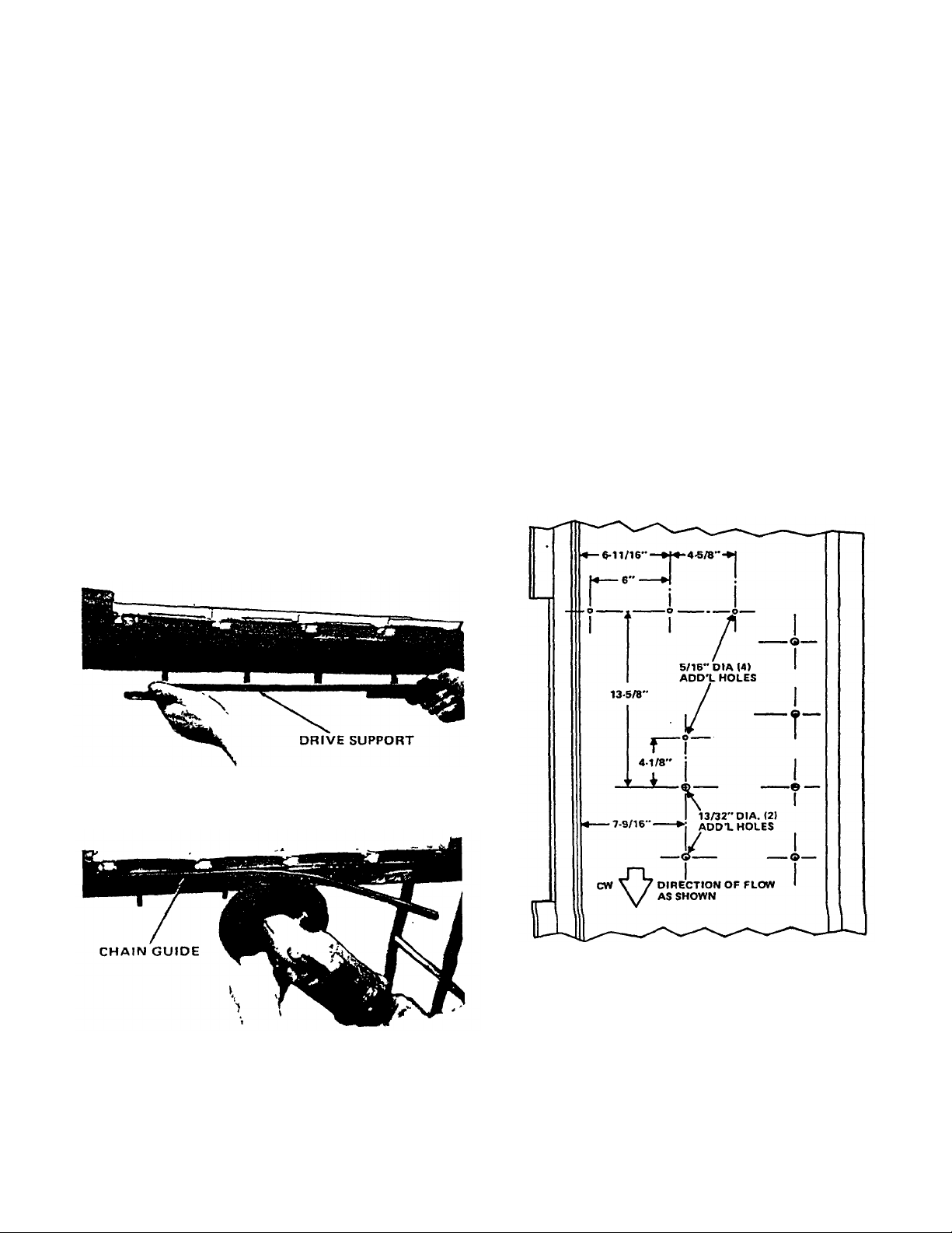
4. Remove both front and back drive supports (W-2-14148).
(See fig 1.)
INDEX
5. Using a grinder with a cutting disc remove the existing
chain guide (3/16" x 1/2" strip) welded outside the
tables. (See fig 2.)
INSTALLING NEW DRIVE UNIT
1. Determine if machine has clockwise or counter-clockwise
conveyor. Follow directions in fig 3 for drilling holes in
clockwise conveyor, fig 3A for counterclockwise conveyor.
Figure 1. Removing Drive Supports
Figure 2. Removing Chain Guide Welded to Table
2
Figure 3. Drilling Locations for Clockwise Conveyor
Page 3
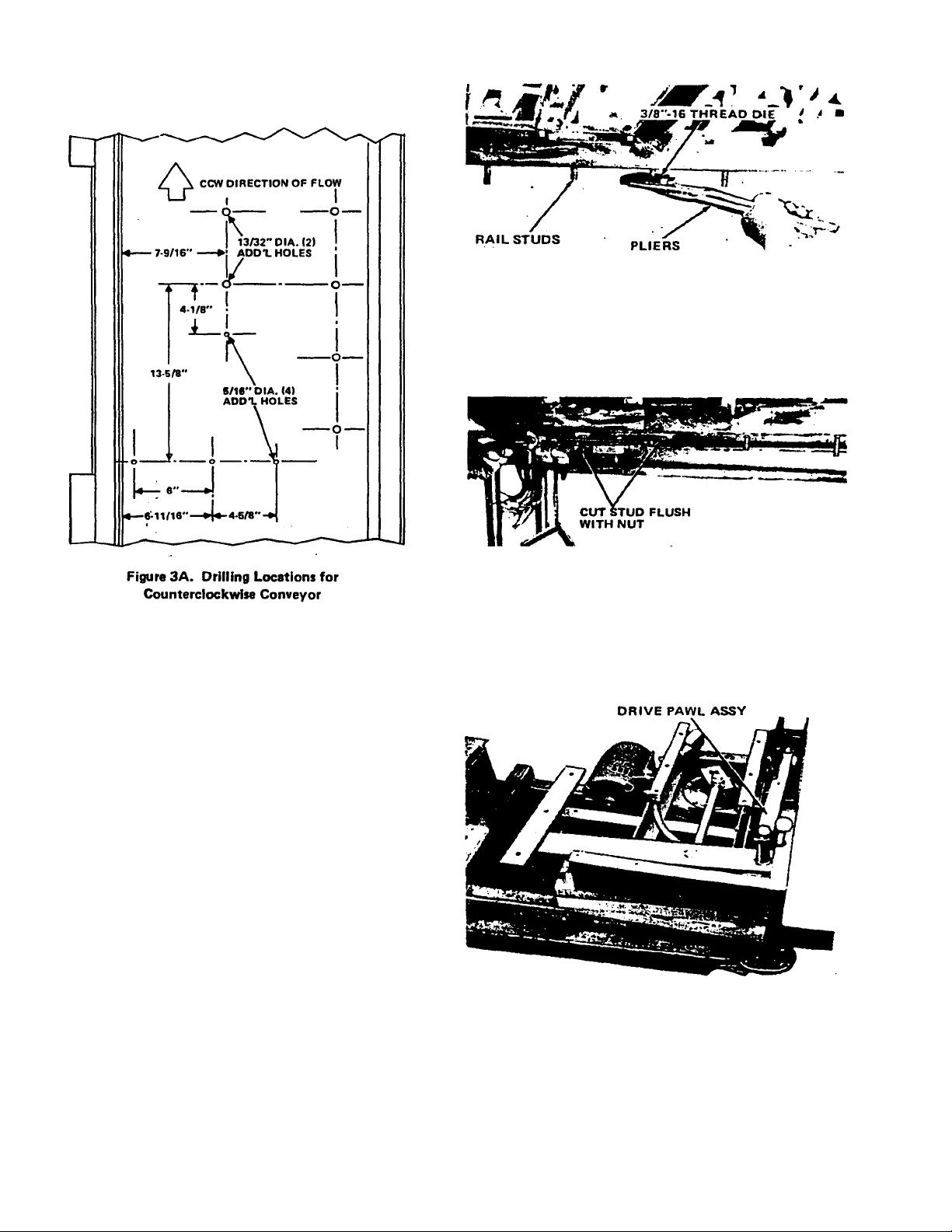
Figure 4. Threading Rail Studs
3. Cut off the excess amount of each stud flush with the
nut. (See fig 8.) This must be done to provide clearance
for drive arm assembly (Item 80 on attached exploded
view).
2. Run additional threads on all four of the existing rail
studs AS CLOSE as possible to the bottom of the
table. Use the 3/8"-16 thread die (W-0-95576) provided
in the kit. A large adjustable pliers or pipe wrench can
be used to run the thread die up the studs. (See fig 4.)
(A) CLOCKWISE MACHINE
Pack a large amount of silicons sealant around
the 2 studs on the left. Place a split lockwasher
and nut on each stud and securely tighten.
(B) COUNTERCLOCKWISE MACHINE
Pack a large amount of silicone sealant around
the 2 studs on the right. Place a split
lockwasher and nut on each stud and securely
tighten.
Figure 5. Cutting Off Studs on Clockwise Conveyor
4. Remove front and rear covers of type "D " drive and
place on lifting device. (See fig 6.)
5. Remove drive pawl assembly (Item 83 on attached
exploded view). (See fig 6.)
Figure 6. Drive Assy Mounted on Lifting Device
3
Page 4

Figure
8.
Fastening Dri
ve to Table
Figure
10.
Checking Drive Arm to Slide Clearance
6. Lift new drive part way into place. (See fig 7.)
7. Reconnect safety limit switch (Item 10 of attached
exploded view). Connect to COMMON and N.O.
terminals. If flexible conduit is not long enough. you may
need a new section of 3/8" flexible waterproof conduit.
CAUTION
9. Attach drive arm pivot weldment (Item 7 of attached
exploded view) to front of table. Be sure Item 46 of
attached exploded view is placed under Item 7 before
attaching lockwashers and nuts. Apply liberal amount of
silicone sealant around top of hole before inserting bolts.
10. Plug unused hole with 3/8" x 16 truss head bolt. Apply
silicone sealant around hole before inserting.
BE SURE FLEXIBLE CONDUIT IS RETAINED BY BOTH
CLAMPS (ITEM 19 ON EXPLODED VIEW). THIS HOLDS
CONDUIT AWAY FROM GEAR REDUCER CRANK.
Figure 7. Lifting New Drive Into Place
8. Lift drive up to the table and fasten, using 3/8"-16 and
1/4"-20 S/S truss head screws as shown. Always apply a
liberal amount of silicone sealant around the hole before
inserting the truss head bolt. (See fig 8.)
11. Reinstall drive pawl assembly. (See fig 9.)
Figure 9. Reinstalling Drive Pawl Assy
12. Check for clearance between drive arm assembly (Item 80
of exploded view) and drive arm slide (Item 53 of exploded
view). You should be able to pass a business card (0.020
shim) between the arm and slide. (See fig 10.) To adjust,
place a shim on one side or the other of the drive arm pivot
weldment. (See fig 11.) Placing a shim as shown in fig. 11
will increase the clearance. Placing a shim on the other side
will decrease the clear-ance (hack saw blade(s) work very
well as shims).
4
Page 5

13. Make motor connections. Change motor overloads to
Figure
11.
Adjusting Drive Arm to Slide Clearanc
e
Figure
14.
Location of Overload Compression Springs
accomodate heavier 1/2 H.P. motor of type "D" drive.
The kit contains overloads for both old and new style
control boxes and for both 208-230V and 460-480V, 3
Phase, power connections. Old style control boxes used
2 overloads, new style use 3. Select and change the
proper overload from the chart listed below. Use the
extra overloads for other service work.
Figure 12. Checking Drive Pawl to Roller Clearance
208-230 Volts Use 2 E34 Overloads
OLD STYLE CONTROL BOX
440-480 Volts Use 2 E26 Overloads
NEW STYLE CONTROL BOX
208-230 Volts Use 3 N-17 Overloads
440-480 Volts Use 3 N-11 Overloads
ADJUSTMENTS
1. Operate conveyor. When fully retracted, drive pawl
assembly (Item 83) wilt be approximately 1/2 inch in
back of roller. (See fig 12.)
The stroke of the drive is fixed at 6 inches. The
connecting rod (item 64, page 7) should be adjust ed so
that the drive arm assembly (item 80, page 7) clears
both sides of the drive equally. (See fig. 13.)
2. Setting Conveyor Overload Switch.
The following test should be performed on every
Flight-A-Round dishwasher service call, even when
there is no apparent conveyor problem. Machine
damage due to improper setting of the overload safety
switch adjustment nut is not covered under warranty.
Misaligned tracks or other binds in the track wilt make
the overload switch ineffective. Be sure conveyor
flows freely around the table before setting the
switch. Usually, conveyor misalignments or binds can
be easily located. In the event that they cannot,
remove the entire conveyor from the machine. Then
manually push a 4 foot section of conveyor around
the table to locate the obstruction. Fig 14 shows the
side of the drive with the cover removed, exposing the
compression springs.
5
Page 6

Use a testing scale for conveyor overload safety
Figure
15.
Testing Conveyor Overload Switch Setting
switch (Pan No. W-0-18410) or a 50 pound fish scale.
To hold the testing scale. Insert a 9-inch piece of 1/2
inch pipe or thinwall through the eyelet of the scale.
Test and adjust the overload safety switch setting as
follows:
(A) Press conveyor START switch.
(B) Position yourself at a curved section of the
Flight-A-Round table, preferably the curve
farthest from the conveyor drive assembly.
nut or loosen the spring compression nuts
until the conveyor stops. (Loosen both
nuts evenly.) Turn clockwise to increase
tension.
(F) Recheck overload safety switch setting and
repeat adjustment until conveyor stops
within the 40 to 50 pound ran ge. Lock the
adjustment nuts in position with the
lockouts. Recheck safety switch setting
after the locknuts have been tight-ened and
readjust if necessary.
(C) With conveyor running, insert hook end of
the scale around the last outboard spacer of
a carrier as shown in fig 15.
(CW Shown)
(D) Pull back on scale, noting scale reading.
Conveyor must stop when scale reading is
between 40 and 50 pounds with conveyor
empty.
FINAL ASSEMBLY
1. Install all covers and check all screws for proper
tightness.
2. Install 4-Inch section of carrier link shield over spot
vacated by type "C" drive cover. You will probably have
to customize here. Usually the carrier shields on both
sides of the drive must be removed, cut back and new
mounting holes drilled. This will provide a mounting
surface for the new shield. BE SURE TO RADIUS ALL
SHARP CORNERS. (See fig 16.)
3. If machine is equipped with one man cost control, it will
probably be necessary to reset the cost control timer.
Refer to Section 13-37 of your Service Manual for
Modular Dishwashers for complete recalibration
instructions.
Figure 16. New Carrier Link Shield Installed
(E) If conveyor does not stop, turn off the conveyor
6
and adjust tension of overload arm extension
springs. Loosen the lock-
Page 7

PARTS LIST
(CLOCKWISE DIRECTION - - - COUNTERCLOCKWISE DIRECTION)
FLIGHT-A-ROUND DRIVE ASSEMBLY TYPE "D"
7
Page 8

Motor Mount Weldment
Single Groo
ve
"V"
Pulley,
3/8"
Bore,
4.25"
O.D. for
5
FPM (Optional
Single Groove
"V"
Pulley,
5/8"
Bore,
2.25"
O.D. for
6.6
PPM (Standard
44B W -1-10985
Single Groove
"V"
Pulley,
5/8"
Bore,
2.5"
O.D. for
8.5
FPM (Optional
1
Single Groove
"V"
Pulley.
5/8"
Bore,
3.0"
O.D. for
10.5
FPM (Optional
PARTS LIST
(CLOCKWISE DIRECTION - - - COUNTERCLOCKWISE DIRECTION)
ITEM
PART NO. DESCRIPTION QTY
NO.
1 W -2-95461 Rail Weldment Assy (Includes Items 2 thru 4) 1
2 W-1-7118 Screw. SS Hex Hd Mach., 1/4-20 x 1/2" Ig. 8
3 W-1-7007 Lockwasher, SS Split. 1/4" 15
4 W-1-7905 Stat-0-Seal, 1/4" 2
5 W-1-5998 Nut, SS Hex, 3/8-16 5
6 W-1-7524 Lockwasher. SS Split, 3/8" 5
7 W-2-95173 Drive Arm Pivot Weldment 1
8 W-0-14146 Screw, SS Truss Hd Slotted Mach., 3/8-16 x 1-1/2" Ig 2
9 W-0-14185 Screw, SS Truss Hd Slotted Mach., 3/8.16 x 1" Ig. 3
10 W-1-7235 Micro Switch 1
11 W-1-7654 Connector, Straight Liquid Tight, 3/8" 1
12 W-1-95453 Overload Switch Bracket 1
13 W-1-7023 Lockwasher, Plated Split. 1/4" 10
14 M -1-3571 Screw, Hex Hd Plated Steel Cap. 1/4-20 x 1/2" Ig. 5
15 W-2-95158 Drive Base Support, R.H. 1
16 W-0-14784 Bolt. Hex Hd Plated Steel. 5/16-18 x 3/4" 9
17 W-1-8491 Screw. SS Truss Hd Slotted Mach., 1/4-20 x 5/8" Ig. 3
18 W-1-7146 Nut, SS Hex. 1/4-20 9
19 W-1-12977 Conduit Clamp. One Hole, 1/2" 2
20 W-1-7012 Nut, Hex, Plated Steel, 1/4-20 6
21 W-1-8348 Screw. Hex Hd Steel, 1/4-20 x 3/4" Ig. 2
22 W-1-7657 Bolt. Hex Hd, Plated Steel, 3/8-16 x 1-1/4" Ig. 2
23 W-1-7584 Washer, 16 Ga, SS Plat, 13/32" I.D.x 1" O.D. 2
24 W-1-16493 Washer, Nylon Pivot 4
25 W-1-16492 Sleeve, Driven Base Pivot 2
26 P -1-17245 Lockwasher, Plated Split, 3/8" 5
27 W -0-14785 Nut, Hex, Plated Steel. 3/8-16 7
28 W-1-95I62 Overload Spring Bar 1
29 1-9268 Compression Spring (.177 Dia. Wire) 1-1/32" I.D. x 2" high 2
30 W-1-95191 Spring Washer 4
31 M -1-15062 Bolt. Hex Hd Steel. 3/8-16 x 3-1/2" Ig. 2
32 W-1-95199 Drive Base End Panel 1
33 W-1-95193 Drive Belt Tightener Assy (Consists of Items 34 thru 38) 4
34 W-0-95192 Flat Plate 1
35 P -1-17235- Lockwasher, Plated Split, 5/16" 18
36 W-0-14786 Nut, Hex Plated Steel, 5/16-18 18
37 M -1-15069 Screw, Hex Hd Steel. Fully Threaded, 5/16-18 x 2-1/2" Ig 1
38 W-0-14099 Bolt. Carriage, Plated Steel, 5/16-18 x 3/4" Ig. 4
39 W-1-11312 Motor, 1/2 HP 115/230V Single Phase, Type 56-4 Frame 1
39A W-1-11314 Motor, 1/2 HP 208/230/460V Three Phase. Type 56-4 Frame 1
40 W-1-14945
41 W -1-9859 Washer. 16 Ga. SS Flat, .337" I.D. x 7/8" O.D. 2
42 W -1-95163 Motor Mount Hanger 1
43 W -0-95465 Bolt, Sq. Hd Plated Steel, 3/8-16 x 7" Ig. 1
44 W -1-11328
44A W -0-14753
FLIGHT-A-ROUND DRIVE ASSEMBLY TYPE "D"
REQ.
1
1
1
8
44C W -0-10984
1
Page 9

ITEM PART
QTY
46 W-1-95450
-A
Motor Cover Mount
1
50 W-1-95156
Drive Bas
e Weldment
1
53 W-1-95190
Drive Arm Slide
1
6.6
(Standard) FPM Speeds
1
56 W-0-14097
Speed Reducer,
60:1
1
58 W-1-95167
Crank Weldment w/Setscrew
1
65 W-0-95455
Rod End
2
68 W-2-95468
-A
Drive Pawl Guard Assy (Consists of One Item
3,
One Item
18,
and Items
69
thru
74) . 1
72 W-1-14198
Delrin Roller,
15/16"
O.D. 2
74 W-1-95462
Drive Pawl Guard Base
1
77 W-2-95177
-A
Drive Enclosure
1
PARTS LIST
FLIGHT-A.ROUND DRIVE ASSEMBLY TYPE "D"
(CLOCKWISE DIRECTION - - - COUNTERCLOCKWISE DIRECTION)
NO. NO. DESCRIPTION REQ.
45 W-0-16891 "V" Belt, 25" OAL for Clockwise Drive 5 and 8.5 FPM Speeds 1
45A W-1-11331 "V" Belt, 26" OAL for Clockwise Drive 6.6 and 10.5 FPM Speeds 1
45B W-0-95456 "V" Belt, 35.2" OAL for Counterclockwise Drive 5 and 8.5 FPM Speeds 1
45C W-0-95457 "V" Belt. 36.2" OAL for Counterclockwise Drive 6.6 and 10.5 FPM Speeds 1
47 W-1-95451 Drive Motor Cover 1
48 W-1-95452 Motor Cover Lower Bracket 1
49 W-2-95178 Pulley and Belt Cover 1
51 W-2-95161 Drive Mount Rear Support 1
52 W-2-95159 Drive Base Support, L.H. 1
54 W-1-11335 Screw, Hex Hd SS Fully Threaded, 1/4-20 x 1.1/4" Ig. 3
55 W-1-11331 Single Groove "V" Pulley, 5/8" Bore, 5.0 O.D. for 5 (Optional) and
55A W.O-14281 Single Groove "V" Pulley. 5/8" Bore, 4.25" O.D. for 8.5 and
10.5 FPM (Optional Speeds) 1
57 W-1-8067 Bolt, Hex Hd Plated Steel. 5/16-18 x 1" Ig. 4
59 W-0-14192 Jam Nut, Hex Plated Steel. 1/2-13 1
60 M -1-15317 Lockwasher, Plated Split, 1/2" 2
61 M -1-15151 Washer. Plated Steel Flat, 17/32" I.D. x 1-1/16" O.D. x 3/32" thick 6
62 W-0-95466 Bolt, Hex Hd Plated Steel 1-1/4" Ig. thread) 1/2-13 x 2" Ig. 2
63 P -1-17237 Nut, Hex Plated Steel, 1/2-13 . 1
64 W-1-954 54 Connecting Rod Assy (Consists of Items 65 thru 67) 1
66 W-0-95459 Jam Nut. Hex 1/4-20 2
67 W-1-95164 Connecting Rod 1
69 W-0-95485 Bolt, Hex Hd SS. 1/4-20 x 3" Ig. 1
70 W-1-8622 Washer. Flat, 18 Ga. SS, 17/64" I.D. x 5/8" O.D. 3
71 W-1-14517 Tubular Spacer, 3/4" Ig. 1
73 W-1-95458 Tubular Spacer, 1-3/4" Ig. 1
75 W-1-95170 Drive Enclosure Mounting Bracket 1
76 W-1-967 7 Screw, Hex Hd Mach., SS, 1/4-20 x 3/4" Ig 5
78 W-0-18190 Pin, SS Roll, 1/4"Dia.x 1-3/4"lg. 1
79 M -1-15208 Set Collar, w/setscrew, plain steel, 1"I.D.x 1-5/8" x 5/8" thick 1
80 W-2-95176 Drive Arm Assy (Consists of Items 81 and 82) 1
81 W-2-95175 Drive Arm Weldment 1
82 W-1-9868 Oilite Flange Bearing 1
83 W-3-95197 Drive Pawl Assy (for CCW Drive) (Consists of One Item 73 and Items 84 thru 89) 1
83A W-3-95196 Drive Pawl Assy (for CW Drive) (Consists of One Item 73 and Items 84A thru 89) 1
84 W-3-95195 Drive Pawl Weldment (CCW Drive) 1
84A W-3-95194 Drive Pawl Weldment (CW Drive) 1
9
Page 10

PARTS LIST
FLIGHT-A-ROUND DRIVE ASSEMBLY TYPE "D"
(CLOCKWISE DIRECTION - - - COUNTERCLOCKWISE DIRECTION)
ITEM
NO.
85 W-0-14392 Screw. Hex Hd Mach., SS. 3/8-16 x 2" 1
86 W-1-95189 Drive Pawl Roller 1
87 W-1-95187 Pawl Roller Sleeve 1
88 W-0-16161 Nut, SS Hex Acom, 3/8-16 1
89 W-0-95460 Oilite Flange Bearing 2
90 P-1-17237 Nut. Plated Steel. 1/2 -13 1
91 M-1-15317 Lockwasher. Split Plated, 1/2" 1
92 W-1-12836 Washer, Flat, 16 Ga. SS, 17/32" I.D. x 1-1/4" O.D 1
93 W-1-95198 Pawl Driving Arm Stud 1
94 W-1-95372 Pawl Cam Cover 1
95 W-1-95374 Drive Pawl Cam 1
96 W-1-95458 Cam Spring Spacer 1
97 1-8879 Compression Spring, 9/16" O.D. x 1-3/4" lg. 1
98 W-1-7145 Screw, Hex Hd Mach., SS, 1/4-20 x 2-1/4" lg. 1
99 W-2-95371 Drive Pawl Guide 1
100 W-2-95179 Pawl Support Assy 1
PART NO. DESCRIPTION
NOTE: The drive assembly pictured is for counterclockwise direction. When a
clockwise direction is required, the complete unit is turned 180°.
QTY
REQ.
10
 Loading...