

Page 1
BB914
BB2016
OWNER'S MANUAL
MODELS BB914, BB2016 and BB1224
BURNISHERS
BLAKESLEE
1841 South Laramie Avenue
Chicago, IL 60650
Phone: (708) 656-0660
BB1224
BLAKESLEE
66 Crockford Boulevard
Scarborough Ontario. Canada M1 R 3C3
Phone: (416) 751-2625
Page 2

TABLE OF CONTENTS
SECTION 1 INTRODUCTION 1
1-1 General 1
1-2 Description 1
1-3 Specifications 1
SECTION 2 INSTALLATION 3
2-1 Unpacking the Unit 3
2-2 Installation 4
SECTION 3 OPERATION 7
3-1 General 7
3-2 Preparing Compound Solution 7
3-3 Operation 7
3-4 Draining and Cleaning the Unit 8
SECTION 4 MAINTENANCE 9
4-1 Daily 9
4-2 Monthly 9
4-3 Bi-Monthly 9
4-4 Replacing Tub Drain Screen 9
4-5 Media Replacement 10
4-6 Motor Belt Replacement and Adjustment 10
4-7 Converting "V" Belt Drive to "O- Ring" Drive 10
4-8 Eccentric Bearing Replacement 11
4-9 Media Tub Replacement 12
4-10 Compound Pump 13
4-11 Drive Motor Rotation 13
4-12 Wiring Diagrams and Schematics 13
4-13 Troubleshooting 14
SECTION 5 ILLUSTRATED PARTS LIST 15
Page 3

wx
1-1. GENERAL
This manual covers Installation, Operation, and Maintenance
Instructions and Illustrated Parts Lists for Blakeslee Burnishers Models BB914, BB2016 and BB1224.
1-2. DESCRIPTION
The Blakeslee Burnisher uses a special procelain ceramic
1-3. SPECIFICATIONS
SECTION 1
INTRODUCTION
burnishing media and chemical compound that restores luster to
stainless steel, silver, pewter, etc.
These procelain ceramic burnishing balls are 1/3 lighter than steel
balls, consequently all types of flat and hollow ware items can be
burnished without damage. Knives and other items are not dulled
no matter how long they remain in the machine.
Motor 1/2 H.P., 3450 RPM 1 H.P., 3450 RPM 1 H.P., 3450 RPM
Compound Pump P:AAA (Constant) 6 GPH P:AAA (Constant) 6 GPH* P:AAA (Constant) 6 GPH*
Media Capacity 40Lbs 160 Lbs 160 Lbs
Weight 140 Lbs, w/o media 265 Lbs, w/o media 265 Lbs, w/o media
Dimensions
Power Requirement 6 amp 115V 12amp 115V 12amp 115V
Tub Opening 9"x 14" 20"x 16" 12"x24"
*Compound pumps on later model burnishers operate in conjunction with a 1 minute timer. When the burnisher is initially turned on,
the pump will run for 2 minutes, then turn off.
BB914 BB2016 BB1224
20-3/4" 1 x 1 5-3/4"
35-5/8" h
20" 1 x 23" w x 35" h 37" 1 x 25" w x 30" h
1/2
Page 4
2-1. UNPACKING THE UNIT
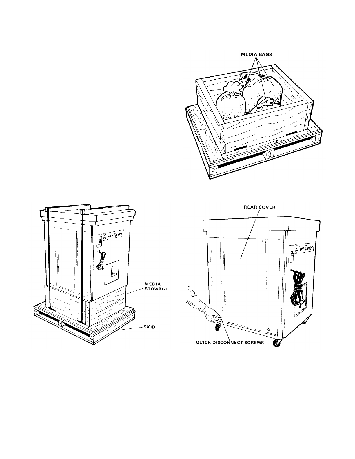
1. Remove unit from shipping carton (See fig. 2-1.)
2. Lift unit from skid.
3. MODEL BB914. Remove media bags stowed in tub.
MODELS BB2016 and BB1224. Remove media bags stowed
inside skid. (See fig. 2-2.)
4. MODELS BB914 and BB2016. To remove rear cover, push
in and turn quick disconnect screws 1/4 turn
counterclockwise. (See fig. 2-3.)
MODEL BB1224. To open front doors, push in and turn quick
disconnect screws 1 /4 turn counter-clockwise. (See fig. 2-4.)
5. Remove compound tank from unit. (See fig. 2-5.) Remove
packing material and compound from tank.
SECTION 2
INSTALLATION
Figure 2-2. Location of Media Bags (Models BB2016 and
BB1224)
Figure 2-1. Model BB2016 with Shipping Carton Removed Figure 2-3. Removing Rear Cover (Model BB2016)
3
Page 5
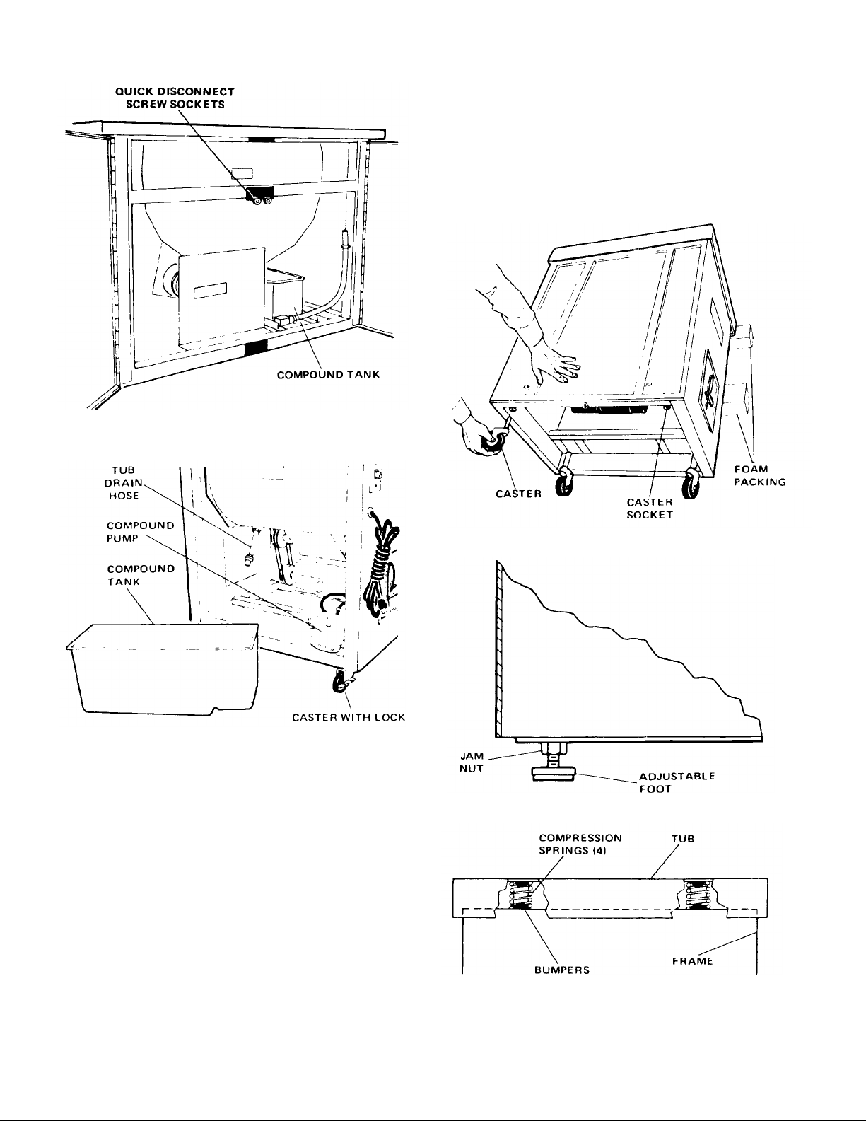
MODEL BB1224. Place unit in desired operating location
(near floor drain if possible). Level machine by loosening
jam nut on adjustable feet and screwing feet in or out until
unit is level. (See fig. 2-7.)
Figure 2-4. Model BB1224 with Front Doors Open
2. Be sure that compression springs are positioned
correctly between upper and lower bumpers. (See fig. 2-
8.)
Figure 2-6. Installing Casters (Model BB2016)
Figure 2-5. Compound Tank Removed (Model 2016)
2-2. INSTALLATION
1. MODELS BB914 and BB2016. Lay unit on its side on
some of the foam packaging (to prevent scratching the
finish) and install casters to bottom of unit. (See fig. 2-6.)
NOTE: One of the casters has a brake (large wing type nut
on side of wheel). The most convenient location for
the brake caster is the corner directly under the motor
starting switch. (See fig. 2-5.)
4
Figure 2-7. Adjustable Foot (Model BB1224)
Figure 2-8. Compression Springs Properly Positioned
Page 6
3. Check the following to make sure nothing has come loose
during shipment:
A. Drain hose assembly attached to tub.
B. Compound hose connected to compound pump and
tub.
C. Cords, hoses clear of motor belts.
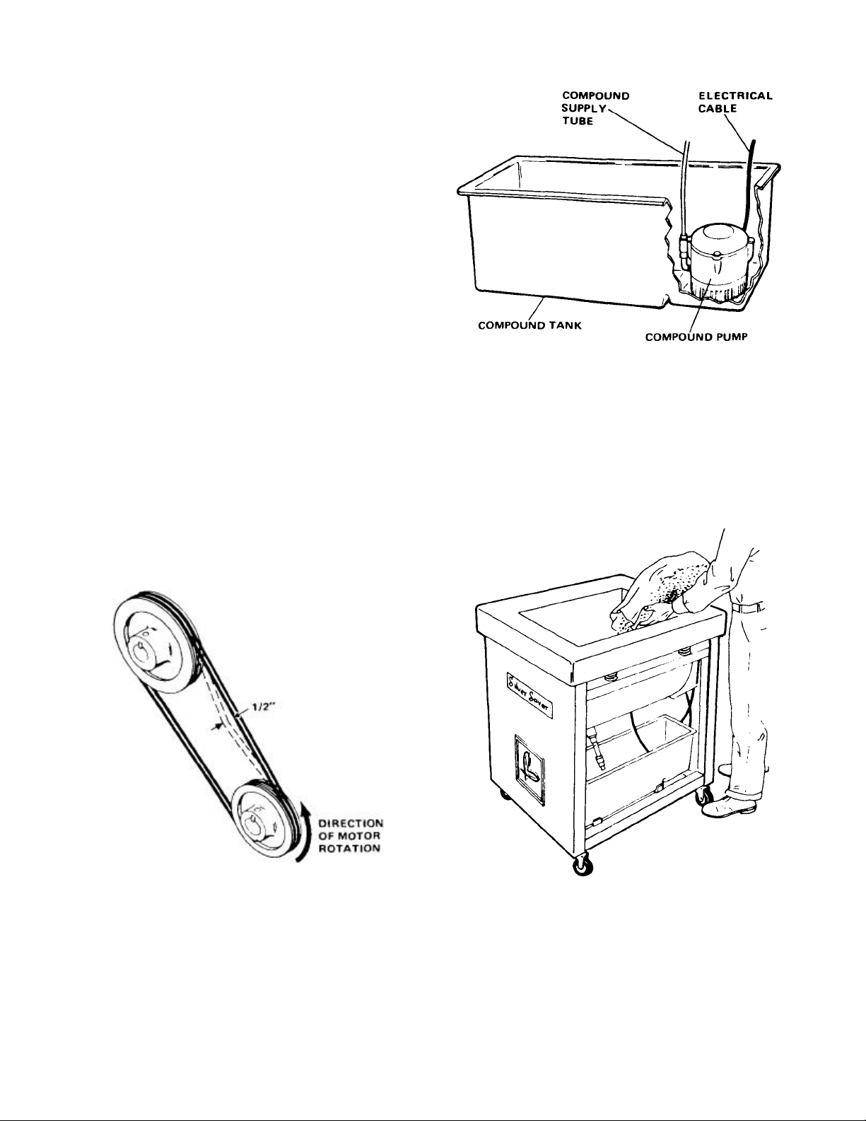
4. Check Motor 0-ring belts for correct installation and
tension (see fig. 2-9). If belt deflection is not approximately
1/2 inch, adjust as described in MOTOR BELT
REPLACEMENT AND ADJUSTMENT (paragraph 4-6).
5. Uncoil motor cable and place on floor next to unit.
6. Install compound tank in unit and place compound pump
in recess in bottom of tank. (See fig. 2-10.)
7. Place end of tub drain hose in compound tank.
8. Clean inside of media tub with a cloth dampened in
menthal alcohol.
Figure 2-10. Compound Pump Installed In Tank
9. Open bag(s) and empty media into tub (approximately
two level inches below compound inlet to tub). (See fig. 2-
11.)
10. If unit is to be put into service immediately, refer to
operating instructions. If unit is not to be put into service
immediately, replace cover.
Figure 2-9. Checking Belt Tension Figure 2-11. Emptying Media Bags Into Tub
5/6
Page 7
3-1. GENERAL
Before putting unit in operation, be sure all steps outlined in
installation instructions have been covered.
NOTE: On initial start-up, it is desirable to flush media
before initial use. This is accomplished by going
thru steps described in paragraph 3-2 and
running unit for approximately 1/2 hour, then
draining the unit by following steps
described in paragraph 3-4.
IMPORTANT
USE ONLY BLAKESLEE SPECIAL COMPOUND. USE OF
OTHER COMPOUND MAY GIVE INCOMPLETE OR
UNSATISFACTORY RESULTS. IN SOME CASES
DAMAGE TO FINE SILVER COULD OCCUR.
UNDER NO CIRCUMSTANCES SHOULD ITEMS BE
PLACED OR SOAKED IN DETAR-NISHING SOLUTION
BEFORE BEING PLACED IN BURNISHER.
SECTION 3
OPERATION
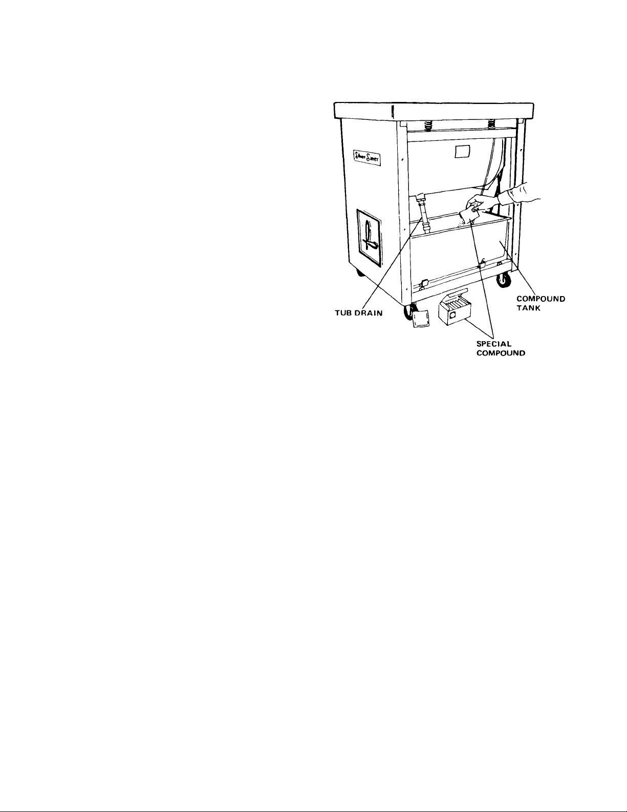
3-2. PREPARING COMPOUND SOLUTION
(See fig. 3-1.)
1. MODEL BB914. Remove rear cover and add one oz. of
compound to compound tank.
MODEL BB2016. Remove rear cover and add two oz. of
compound to compound tank.
MODEL BB1224. Open front door and add two oz. of
compound to compound tank.
2. Be sure end of tub drain hose is in compound tank and
external drain hose is held in vertical position by the clip
(BB1224 only).
3. Fill compound tank with water to full line (approximately
1 -1/2 inch from top of tank).
3-3. OPERATION
1. MODELS BB914 and BB2016. Replace rear cover. Place
unit in desired operating position and lock brake on caster
located under ON-OFF switch.
Figure 3-1. Adding Special Blakeslee Compound to Tank
(Models 914 & 2016)
2. Plug power supply cord into any convenient 115V outlet.
NOTE: Model BB914 requires 6 amp 115V circuit.
Models BB2016 and BB1224 require 12 amp
115V circuit.
3. MODEL BB914 and EARLY MODELS BB2016.
Turn unit on. Motor and compound pump will continue to
run as long as switch is in the ON position.
MODEL BB1224 and LATE MODELS BB2016.
Turn unit on. Compound pump will run for approximately
two minutes then stop automatically. This charge is
adequate for 6 hours of operation under normal operating
conditions.
NOTE: If unit is turned off for any reason, wait 10
minutes before restarting.
4. Deposit washed items in Burnisher tub.
7
Page 8

Figure
3-2.
Draining Compound Tank (Model
BB1224)
5. MODEL BB914 will hold approximately 144 pieces of
mixed flatware.
MODELS BB2016 and BB1224 will hold approximately
576 pieces (4 gross) of mixed flatware.
Burnishing a large amount of similar items (all knives, all
forks, etc.) at one time is not recommended. Normal
burnishing time is 10 minutes. Naturally this will depend on
the condition of the ware. Items that have not been
burnished for a long period will require more time. A weekly
burnishing program will decrease the amount of burnishing
time and keep all items looking like new.
NOTE: Items need not be detarnished. If you choose to
detarnish, items MUST be run through
dishwasher again before being placed in
Burnisher (all items must be dishwasher clean
before processing in Burnisher System).
2. MODELS BB914 and BB2016. Remove rear cover.
Remove compound tank from unit and discard compound
solution. Clean tank with fresh water and reinstall in unit.
MODEL BB1224. Open doors and drain compound
solution by removing external drain hose from clip and
allowing solution to drain into a suitable receptacle or floor
drain. (See fig. 3-2.) Flush and clean compound tank with
fresh water.
NOTE: Compound must be replaced daily for best results.
3. No cleaning of media is necessary.
6. Condition of flatware can be checked while the
7. After desired burnishing results have been obtained,
8. Burnished items must then be processed through your
9. If more items are to be burnished, repeat steps 4 thru 8.
unit is in operation by observing the items as they rotate in
the tub or they can be removed for closer visual
inspection.
remove all items from tub. It is best to remove items from
the machine while it is in operation.
NOTE: Do not remove the media (porcelain ceramic
balls).
dishwashing system in the normal fashion.
3-4. DRAINING AND CLEANING THE UNIT
1. If Burnisher will not be used for the remainder of the day,
turn off the switch and allow system to drain for a few
minutes.
8
Page 9

4-1. DAILY
1. Empty and clean compound tank using fresh water and
soap.
2. Clean inside and outside of unit with a soft damp cloth.
Stainless steel components should be cleaned with
stainless steel cleaner and polish.
3. Check to be sure screen in media tub drain is clear of
foreign objects. On later model BB2016 and BB1224
Burnishers this screen is located on the end of the drain
hose inside the faucet aerator. Remove the aerator and
clear or dislodge foreign objects using a wooden toothpick
or similar item. (See fig 4-1.)
NOTE: Grasping the tubing tightly or bending the tubing
up will prevent any media from falling out when
the aerator is removed. (See fig 4-2.) A small
cork or rubber stopper can then be inserted in
the coupling until the aerator is reinstalled.
SECTION 4
MAINTENANCE
Figure 4-2. Grasping Drain Tube to Prevent Media from Falling
Out
Figure 4-1. Cleaning Tub Drain Screen
4-2. MONTHLY
Check condition of motor belts and hoses. Replace as necessary.
See MOTOR BELT REPLACEMENT AND ADJUSTMENT
(paragraph 4-6).
4-3. BI-MONTHLY
Lubricate both vibrator bearings through grease fittings provided on
flanged bearing assy. Use good grade (E.P.O.) of bearing grease.
4-4. REPLACING TUB DRAIN SCREEN (Early Models)
On model BB914 and older models BB2016 and BB1224 the tub
drain screen is located inside the media tub in the tub drain inlet.
The redesigned hose assy. can be retrofitted on models BB2016
and BB1224 (except some very early models) by simply prying the
old screen out of the tub drain inlet (see fig 4-3) and installing the
new drain hose assy. (part no. W-0-95016).
Figure 4-3. Removing Tub Drain Screen From Early
Models BB2016 and BB1224
9
Page 10

4-5. MEDIA REPLACEMENT
The best burnishing results are obtained when both 1/8" and 1/4"
porcelain-ceramic media (balls) are mixed. Proper mixture is 3 parts
1/8" media (white color) to one part 1/4" media (blue color) by weight.
The burnishing media supplied with your machine has been premixed as described above. When replacement media is ordered, it
also will be mixed as shown above.
ALL MODELS USING "V" BELT DRIVE
1. Removal and replacement is the same as for O-ring belts
except that the motor mount bolts must be loosened in
order to remove or replace the belt.
2. Adjustment is the same as O-ring belts.
4-7. CONVERTING "V" BELT DRIVE TO "O-
RING" DRIVE
MODEL BB914. Parts needed for conversion are as follows:
4-6. MOTOR BELT REPLACEMENT AND
ADJUSTMENT
MODELS BB914 and BB2016. Remove rear covers by
turning quick disconnect screws 1/4 turn counterclockwise.
MODEL BB1224. Open front doors by turning quick
disconnect screws 1/4 turn counterclockwise.
CAUTION
MAKE SURE SWITCH IS OFF AND POWER CORD IS
DISCONNECTED FROM WALL OUTLET.
ALL MODELS USING DOUBLE "O-RING" TYPE BELTS.
1. Because these belts have more "stretch" than ordinary
"V" belts they can be removed and replaced without
loosening the motor mounts. Simply pull the belt to the top
of the pulley groove and rotate pulley by hand until belt
pops off. These belts should be replaced in sets.
2. Install new belts making sure belts are seated properly
in grooves and are not twisted.
3. Check belt tension for approximately 1/2-inch deflection
when moderate pressure is applied to belts as shown in
fig. 2-9. If adjustment is required, loosen motor mount
bolts and slide motor until proper tension is obtained.
NOTE: Media tub should be filled with proper amount of
media before checking or adjusting belt tension.
Double groove driven pulley ..……….... W-0-20456
Double groove drive pulley .....………... W-0-20458
Special "O-ring" belt (2 required) . . ….. W-0-20459
1/2 hp, 3450 rpm motor ......………….... W-0-95057
CAUTION
MAKE SURE SWITCH IS OFF AND POWER CORD IS
DISCONNECTED FROM WALL OUTLET.
1. Disconnect electrical wires from motor.
2. Remove bolts securing motor to motor mount plate.
3. Remove "V" belt and motor.
4. Remove driven pulley from eccentric shaft.
5. Install new 3450 rpm motor with the same bolts used on
the old motor.
6. Connect electrical wires to motor terminals.
7. Install driven pulley (large diameter) on eccentric shaft with
setscrew side of hub facing out.
8. Install drive pulley (small diameter) on motor shaft with
setscrew side of hub facing out.
9. Using a straight edge or ruler, adjust the pulleys so they
are exactly in line (see fig. 4-4) then tighten setscrews.
10. Install new belts as described in MOTOR BELT
REPLACEMENT AND ADJUSTMENT (paragraph 4-6).
10
Page 11

Figure 4-4. Checking Pulley Alignment
MODEL BB2016. Parts needed for conversion are as follows:
Double groove driven pulley ..……... W-0-20456
Double groove drive pulley ..……..... W-0-20457
Special "O-ring" belt (2 required) . . . W-0-20459
1 hp, 3450 rpm motor .....………….... W-0-95058
CAUTION
MAKE SURE SWITCH IS OFF AND POWER CORD IS
DISCONNECTED FROM WALL OUTLET.
1. Disconnect electrical wires from motor.
2. Remove the entire motor and motor mount assy. (see fig.
5-3). These parts will not be reused.
9. Using a straightedge or ruler, adjust the pulleys so they
are exactly in line (see fig. 4-4) then tighten setscrews.
10. Install new belts as described in MOTOR BELT
REPLACEMENT AND ADJUSTMENT (paragraph 4-6).
4-8. ECCENTRIC BEARING REPLACEMENT
1. Remove front cover, rear cover, and guards as necessary
to gain access to both flange bearings.
2. Remove drive belts.
3. Remove driven pulley from eccentric shaft.
4. Model BB914 refer to insert in fig. 5-1. Models BB2016
and BB1224 refer to fig. 5-4. Remove three bearing
bolts, nuts, and lockwashers.
5. Remove flange bearings and eccentric shaft assy. from
housing.
NOTE: If the unit is still equipped with the old style 2
piece lead weight it should be converted at this
time to the one piece steel weight. Refer to parts
list for parts required for conversion.
6. Reinstall eccentric shaft assy. in housing.
7. Install flange bearings on eccentric shaft and line up bolt
holes with grease fittings positioned for easiest access for
servicing.
8. Install and tighten three flange bolts, nuts and washers.
3. Remove motor mount plate. Layout and drill two new holes
in the plate as shown in fig. 4-5.
4. Reinstall motor mount plate.
5. Install new 3450 rpm motor.
6. Connect electrical wires to motor terminals.
7. Install drive pulley (small diameter) on motor shaft with
setscrew side of hub facing out.
8. Remove old driven pulley from eccentric shaft and replace
with new double groove pulley (large diameter). Setscrew
side of hub should face out.
9. Install pulley on eccentric shaft and line up pulleys as
shown in fig. 4-4. Tighten setscrew.
10. Install belts and check for proper tension as described in
MOTOR REPLACEMENT AND ADJUSTMENT
(paragraph 4-6).
11. Replace all guards and covers.
12. After unit has run approximately 30 minutes, lubricate
both flange bearings through grease fittings on housings.
11
Page 12

NOTE:
1. DRILL 2 HOLES 11/32 DIA. TO INSTALL ITEMS 2, 3 & 4
FOR BOLTING MOTOR TO MOUNT PLATE.
2. USE OLD 5/16 BOLTS FOR CONVERSION.
Figure 4-5. Layout Drawing for Modifying BB2016 Motor
4-9. MEDIA TUB REPLACEMENT
CAUTION
MAKE SURE SWITCH IS OFF AND POWER CORD IS
DISCONNECTED FROM WALL OUTLET:
1. Remove all media from tub.
2. Remove drive belts.
3. Disconnect compound supply tube from compound
pump.
4. Lift media tub out of unit.
4 A/R
3 2
2 4
1 1
ITEM
Mount Plate
5. Transfer eccentric assy. from old tub to new tub. Refer to
6. Transfer rubber bumpers, compound supply tube and tub
7. Insert new tub into unit making sure springs are properly
8. Reconnect compound supply tube to compound pump.
9. Reinstall drive belts.
10. Remove any foreign objects from tub and wash tub lining
11. Fill tub to proper level with media.
5/16 WASHER
5/16-18 HEX NUT
5/16-18 x 1/2 LG H.H.C.S. PLATED
11 GA C.R. STL 7-15/16 x 22-3/4
QTY. PART NO. DESCRIPTION
ECCENTRIC BEARING REPLACEMENT (paragraph 4-
8).
drain hose assy. to new tub.
positioned (see fig 2-8.)
with methol alcohol.
12
Page 13

4-10. COMPOUND PUMP
The compound pump is the same for all units, however its operation
varies between units. On model BB914 and early model BB2016
the pump continues to run as long as the switch is on. On model
BB1224 and later model BB2016 a timing relay is used to
automatically turn the pump off 2 minutes after the unit is started.
This 2 minute charge is sufficient for approximately 6 hours or until
the unit is turned off. Once the unit is turned off it must remain off
for 10 minutes to allow the compound solution to drain into the
compound tank.
The compound pump is a sealed unit and requires no service or
maintenance. If the pump fails to operate it can easily be replaced
by disconnecting the compound supply tube and wires from the
switch or timing relay.
4-11. DRIVE MOTOR ROTATION
reversed by changing the internal wiring of the motor. Instructions
are usually provided on the motor data plate. When the motor is
rotating properly the media will be pitched as shown in fig 4-6.
The electric drive motor should rotate in a counterclockwise
direction (see fig 2-9). The direction of rotation can be
4-12. WIRING DIAGRAMS AND SCHEMATICS
Figure 4-7. Wiring Diagram, Model BB1224 and
Late Model BB2016
Figure 4-6. Pitch of Media as Viewed from Pulley Side of Tub
Figure 4-9. Schematic, Model BB1224 and Late Model
BB2016
Figure 4-8. Wiring Diagram, Model BB914 and Early
Model BB2016
Figure 4-10. Schematic, Model BB914 and
Early Model BB2016
13
Page 14

4-13. TROUBLESHOOTING
PROBLEM CAUSE REMEDY
Unit fails to operate. Unit not plugged in. Plug in power cord.
Blown fuse or circuit breaker. Replace fuse or reset circuit breaker.
Defective switch. Replace switch.
Drive motor overheats. Eccentric bearings seizing due to lack of lubrication. Lubricate or replace bearings as necessary.
Broken wire in power supply cord. Repair or replace.
Low supply voltage to motor. Check voltage at wall outlet. Possibly too much load
on that circuit. Reduce load on circuit or use
different circuit.
Internal defect in motor. Have motor tested by qualified technician.
Excessive noise. Media tub spring(s) broken or out of position. Replace spring or reposition. See fig. 2-8.
Eccentric bearings worn. Replace eccentric bearings.
Pulleys loose on motor or eccentric shaft. Tighten setscrew in pulley hub.
Media tub fails to maintain proper
level of compound solution.
Eccentric bearings need lubrication. Lubricate bearings through grease fittings.
Drive belts worn or frayed. Replace belts.
Loose covers or panels. Tighten screws.
Compound pump inlet plugged. Compound pump
inoperative.
Timing relay improperly adjusted or inoperative. Late
Model 2016 and Model 1224 only.
Drive motor rotating in wrong direction (new unit or
new motor only).
Clean pump inlet. Replace pump.
Readjust or replace as necessary.
Check that motor rotates counterclock-wise when
facing front of pulley. Have wiring checked by
qualified technician.
14
Page 15

5
ILLUSTRATED PARTS LIST
A
Ib. cartons
18020
To expedite delivery, all parts must be ordered by name and number listed in this parts list.
All orders must include Serial Number of the machine. Place your order with your local
Blakeslee Parts Distributor or Service Agency. Their name and address can be found in the
Service Agency Booklet which accompanies this manual. If you need further assistance,
contact:
BLAKESLEE
1844 So. Laramie Avenue
Chicago, Illinois 60650
Telephone: (312)
REPLACEMENT BURNISHING MEDIA AND CHEMICAL COMPOUND
SECTION
PART
NO.
W-0-18021W-0-18026-A
W-0W-0-18757
DESCRIPTION
Consisting of 1/8" x 1/4" diameter balls mixed, 3 parts 1/8" balls and 1 part 1/4"
balls BY WEIGHT.
8 carton case of 5
1 - 40 Ib. carton
Case of 4 Gallons
Case of 360 - 1 oz. packets
BURNISHING MEDIA
CHEMICAL COMPOUND
15
Page 16

16
Figure 5-1. Model BB914 Main Assembly
Page 17

17
FIG. 5-1. MODEL BB914 MAIN ASSEMBLY
ITEM
NO.
1 W-0-17916 FRAME ASSY, w/electrical box and casters, epoxy painted 1
2 W-0-17917 TUB WELDMENT, Complete w/urethane lining and epoxy paint 1
3 W-0-17919 RUBBER BUMPER 8
4 W-0-17920 SPRING, Painted 4
5 W-0-17921 CASTER, w/brake, w/o bracket 1
6 W-0-18018 CASTER, w/o brake, w/o bracket 3
7 W-0-17922 BRACKET, For casters, unpainted 4
8 W-0-17923 ABS GUARD, Left side switch opening, w/double coated tape and rivets 1
9 W-0-17924 ABS GUARD, Right side, w/tape and rivets 1
10 W-0-17925 ABS GUARD, Front and/or rear, w/o fasteners 1
11 W-0-17926 FASTENER KIT, Quick disconnect, for front and rear guards,
12 W-0-17942 TOGGLE SWITCH 1
13 W-0-17929 COMPOUND PUMP 110 V 60 Cycle 1
13A W-0-95556 COMPOUND PUMP 230 V 50 Cycle (Export only)
14 W-0-17930 HOSE ASSY, Compound supply, 1/4", w/connectors 1
15 W-0-17931 DRAIN HOSE ASSY, Complete with 5/8" hose 1
16 W-0-17932 COMPOUND TANK 1
17 W-0-17933 FLANGED BEARING ASSY, Painted 2
18 W-0-17935 BEARING BOLT KIT 1
19 W-0-17934 SHAFT, Eccentric 1
20 W-0-20766 ECCENTRIC WEIGHT ASSY, Consists of: 1
21 W-0-20765
22 W-0-20460
23 W-0-7023
24 W-0-20313
25 W-0-20456 PULLEY, Driven, double groove, serial no. 77-001 and up 1
25A W-0-17936 PULLEY, Driven, single groove, serial no. 77-000 and below 1
26 W-0-20458 PULLEY, Drive, double groove, serial no. 77-001 and up 1
26A W-0-17938 PULLEY, Drive, single groove, serial no. 77-000 and below 1
27 W-0-20459 BELT, "O"-Ring type, serial no. 77-001 and up 2
27A W-0-16907 BELT, "V" type, serial no. 77-000 and below 1
28 W-0-95057 MOTOR, 1/2 hp, 3450 rpm, 110/220V, 1 phase, 60 cycle
serial no. 77-001 and up 1
28A P-1-5280 MOTOR, 1/3 hp, 1725 rpm, 110/220V, 1 phase, 60 cycle
serial no. 77-000 and below 1
28 B W-0-95554 MOTOR, 1/2 hp, 3450 rpm, 115/230V, 1 phase, 50 cycle,
serial no. 77-001 and up (Export only)
29 W-0-17940 CABLE, Electrical, between switch and motor 1
30 W-0-17941 CABLE KIT, Electrical, supply, 12 ft 1
31 W-0-17943 COVER, s/s toggle switch 1
32 W-0-17945 FASTENER KIT, Motor mount 1
33 W-0-17927 MEDIA RETURN TOP DECK, w/decal and chrome fastener 1
34 W-0-17928 TUB COVER, Can be used only with media return top deck 1
35 W-0-18618 DECAL, Silver Saver 1
36 W-0-20340 DECAL - Serial no 1
PART NO. DESCRIPTION
3 piece assy 2
i ECCENTRIC WEIGHT
i SCREW, Socket head, 1/4"-28 x 1-1/2" Ig
i LOCKWASHER, 1/4"
i NUT, Hex, 1/4"-28
QTY.
REQD.
1
1
1
1
Page 18

18
Figure 5-2. Model BB2016 Main Assembly
Page 19

FIG. 5-2. MODEL BB2016 MAIN ASSEMBLY
19
ITEM PART
NO. NO DESCRIPTION REQD.
1 W-0-18675 FRAME ASSY, w/electrical box and casters 1
2 W-0-18676 TUB WELDMENT, Complete w/urethane lining 1
3 W-0-17919 RUBBER BUMPER KIT, Consists of (4) rubber bumpers,
4 W-0-17920 SPRING 1
5 W-0-17921 CASTER, w/brake, w/o bracket 1
6 W-0-18017 CASTER, w/o brake, w/o bracket, consists of (3) swivel casters 1
7 W-0-17922 CASTER BRACKET, Consists of (4) brackets 1
8 W-0-18678 COVER, Left side w/switch opening, includes double
9 W-0-18678 COVER, Right side, includes double coated tape and screws 1
10 W-0-18680 COVER, Front and/or rear 2
11 W-0-17926 FASTENER KIT, Quick disconnect, 3 piece assy 4
12 W-0-17942 TOGGLE SWITCH 1
13 W-0-17929 COMPOUND PUMP, 110V 60 cycle 1
13A W-0-95556 COMPOUND PUMP, 220V 50 cycle (export only) 1
14 W-0-17930 HOSE ASSY, Compound supply, 1/4" w/connectors 1
15 W-0-95016 DRAIN HOSE ASSY, Consists of the following parts 1
16 W-0-18681 COMPOUND TANK 1
17 W-0-20459 BELT. "O-ring" type, serial no. 20S-77-001 and up 2
17A W-0-17937 BELT, "V" type, serial no. 20S-77-000 and below 1
18 W-0-20457 PULLEY, Drive, double groove, serial no. 20S-77-001 and up 1
18A W-0-18690 PULLEY, Drive, single groove, serial no. 20S-77-000 and below 1
19 W-0-20456 PULLEY, Driven, double groove, serial no. 20S-77-001 and up 1
19A W-0-18689 PULLEY, Driven, single groove, serial no. 20S-77-000 and below 1
20 W-0-95058 MOTOR, 1 hp, 3450 rpm, 110/220V, 1 phase, 60 cycle
20A W-0-18684 MOTOR, 3/4 hp, 1725 rpm, 110/220V, 1 phase, 60 cycle
20B W-0-95555 MOTOR, 1 hp, 3450 rpm, 110/220V, 1 phase, 50 cycle,
21 W-0-17940 CABLE, Electrical, v//connectors, motor to switch 1
22 W-0-17941 CABLE, Electrical, w/connectors, power supply 1
23 W-0-17943 COVER, s/s toggle switch 1
24 W-0-20336 RELAY, Timing (late production models) 110V, 60 cycle 1
24A W-0-95557 RELAY, Timing (late production models) 220V, 50 cycle (export only) 1
25 W-0-20335 SOCKET. Timing relay (late production models) 1
26 W-0-15971 TIE WRAP. Timing relay (late production models) 1
27 W-0-17945 FASTENER KIT, Motor mount 1
28 W-0-18687 TUB EXTENSION 1
29 W-0-18618 DECAL, Silver Saver 1
30 W-0-18688 TUB COVER 1
31 W-0-18691 HOSE KIT, Compound tank drain, includes connector and
32 W-0-20347 ECCENTRIC SHAFT ASSY (See fig. 5-4 for detail parts) 1
33 W-0-20338 DECAL Pump warning 1
34 W-0-20340 DECAL, Serial No. 1
W-0-20325
(4) 10-24 hex nuts and (4) no. 10 lockwashers 1
coated tape and screws 1
i FAUCET AERATOR
i ADAPTER, Hose connector to aerator
i HOSE CONNECTOR, 1/2" male
i POLYVINYL TUBING. 5/8" x 1/2" x 6-1/2" Ig
i COUPLING Reusable
serial no. 20S-77-001 and up 1
serial no. 20S-77-000 and below 1
serial no. 20S-77-001 and up (export only) 1
spring clip (Early Models Only) 1
QTY.
1
1
1
1
1
Page 20

Figure 5-3. Motor Mount Assembly, Model BB2016 (Serial No. 20S-
QTY.
20
77-000 and Below)
ITEM
NO.
1
PART
NO.
W-0-18806
DESCRIPTION
SUPPORT, Motor bearing
2 W-0-18807 SHAFT, Extension 1
3 W-0-18808 BEARING, Flanged 1
4 W-1-7657 BOLT, Hex head, 3/8-16 x 1-1/4" Ig 3
5 W-1-15334 LOCKWASHER,3/8" 3
6 W-1-7115 NUT, Hex, 3/8"-16 3
7 P-1-17243 SETSCREW. 1/4-10x3/8" lg 1
NOTE: These parts are no longer used starting with serial number 20S-77-001 and up.
When either the motor or flanged bearing need replacing on older models, the
system should be changed to the new style. Refer to Section 4 for instructions on
converting to the new system.
REQD.
1
Page 21

Figure 5-4. Eccentric Shaft Assembly
Models BB2016 and BB1224
ITEM
NO.
1
PART
NO.
W-0-17933
FLANGED BEARING ASSY
DESCRIPTION
2 W-0-20314 GREASE FITTING 2
3 W-0-18683 BEARING BOLT KIT 1
4 W-0-18682 ECCENTRIC SHAFT 1
W-0-20767 ECCENTRIC WEIGHT ASSY, Consists of: 1
6 W-0-20432
7 W-0-20460
8 W-0-20313
9 W-0-7023
i ECCENTRIC WEIGHT
i SCREW, Socket head, 1/4-28 x 1-1/2" Ig
i NUT, Hex, 1/4"-28
i LOCKWASHER. 1/4"
NOTE: When replacing old style 3 piece eccentric weight order item 5, Eccentric
Weight Assy.
QTY.
REQD.
2
1
2
2
2
21
Page 22

22 Figure 5-5. Model BB1224 Main Assembly
Page 23

NO.
NO
REQD.
FAUCET AERATOR
ADAPTER, Hose connector to aerator
COUPLING, Reusable
23
ITEM
PART
FIG. 5-5. MODEL BB1224 MAIN ASSEMBLY
DESCRIPTION QTY.
1 W-0-20315 FRAME WELDMENT
2 W-0-20316 TUB WELDMENT, Complete w/urethane lining
3 W-0-20317 DOOR, Front, RH
4 W-0-20318 COVER, Side, RH
5 W-0-20319 COVER, Back
6 W-0-20320 COVER, Frame, top
7 W-0-20321 TANK, Compound
8 W-0-20322 COVER, Tub
9 W-0-17920 SPRING, Compression 4
10 W-0-20347 ECCENTRIC SHAFT ASSY (See fig. 5-4 for detail parts)
11 W-0-20345 DOOR, Front, LH
12 W-0-17929 PUMP, Compound, 110V, 60 cycle
12A W-0-95556 PUMP, Compound, 220V, 50 cycle (export only) 1
13 W-0-20323 GROMMET 1
14 W-0-17919 RUBBER BUMPER 8
15 W-0-17931 HOSE, Compound supply, w/connectors 1
16 W-0-95016 DRAIN HOSE ASSY, Consists of the following parts 1
17 W-0-95058 MOTOR, 1 hp, 3450 rpm, 110/220V, 1 phase, 60 cycle 1
17A W-0-95555 MOTOR, 1 hp, 3450 rpm, 110/220V, 1 phase, 50 cycle (export only) 1
18 W-0-17941 CABLE ASSY, Electrical, power supply, 12 ft Ig 1
19 W-0-27942 SWITCH, Toggle 1
20 W-0-17943 COVER, Toggle switch, s/s 1
21 W-0-20346 COVER, Side, LH 1
22 W-0-20459 BELT, "O-ring" type 2
23 W-0-20456 PULLEY, Driven, 2 groove 1
24 W-0-20457 PULLEY, Drive, 2 groove 1
25 W-0-20326 FEET, Level mount 4
26 W-0-17926 FASTENER, Quick disconnect, 3 piece assy 2
27 W-0-20327 RIVET, Aluminum 4
28 W-1-5999 SCREW, Rd hd, s/s. 10-32 x 1-1/2" Ig 36
29 W-1-7285 LOCKWASHER, s/s, no. 10 36
30 W-1-7680 NUT, Hex, no.10-24 8
31 W-1-7647 LOCKWASHER,No.10 14
32 W-1-7291 SCREW. Cap, hex hd, 5/16-18 x 1"lg 4
33 W-1-5996 LOCKWASHER. Split, 5/16" 4
34 W-1-5587 WASHER, Flat 5/16"-10 4
35 W-0-18618 DECAL, Silver Saver 1
36 W-0-20328 SCREW, Self tapping washer hd, Rollex, 6-32 x 1/2" Ig
37 W-0-30329 TUBING, Polyvinyl. 5/8" OD x 1/2" ID x 30" Ig
38 W-0-20330 CLIP, Spring
39 W-2-16380 NAMEPLATE, Blakeslee (horizontal)
40
41 W-0-20333 PAN, Frame cover
42 W-0-20334 SPACER. Cover 14
43 W-0-20335 SOCKET, Relay 1
44 W-0-20336 RELAY, Timing, 110V, 60 cycle 1
44A W-0-95557 RELAY, Timing, 220V, 50 cycle (export only) 1
45 W-0-20337 SMITH SHAFT LOCK 1
46 W-0-20338 DECAL, Pump warning 1
47 W-0-15971 TIE WRAP, Timing relay 1
48 W-0-20339 TAPE, Scotch foam, 16 ft. 1
49 W-0-20340 DECAL, Serial no. 1
50 W-2-16380 NAMEPLATE, Blakeslee (vertical) 1
51 W-1-74 76 SCREW 4
52 W-1-7104 NUT 4
53 W-1-8839 LOCKWASHER 4
W-0-20325
i
i
i HOSE CONNECTOR, 1/2" male
i POLYVINYL TUBING, 5/8" x 1/2" x 6-1/2" Ig
i
GUARD, Drive belt
1
1
1
1
1
1
1
1
1
1
1
1
1
1
1
1
1
1
1
1
1
1
 Loading...