

Page 1
Operations Manual
Ultimatte 12
November 2017
English,
Español, 中文, Русский
日本語, Français, Deutsch,
Português.
and
Page 2
Languages
To go directly to your preferred language, simply click on the hyperlinks listed in the
contents below.
English 3
日本語 67
Français 132
Deutsch 197
Español 262
中文 327
Русский 392
Português 457
Page 3

English
Welcome
Thank you for purchasing your Blackmagic Ultimatte 12.
Ultimatte has been the premiere keyer used in the film and television industries for decades and
no other keyer comes close to the performance that Ultimatte can achieve. It’s powerful enough to
handle fine detail on key edges as well as retaining stronger colors, even when those foreground
colors are close to the key color. Even uneven green and blue screen backdrops can be handled.
However, what makes Ultimatte so powerful is its ability to map shadows onto the new background
layer combined with its color spill management that lets you create extremely realistic environments.
In many ways, Ultimatte is much more than a keyer as it’s really a real time advanced compositor for
creating photorealistic virtual environments. Ultimatte lets you move your talent to any location at
the click of a button and the results look real.
Ultimatte 12 is the latest model of Ultimatte and this new model includes entirely new algorithms and
color science, incredible edge handling, greater color separation, amazing color fidelity and better
spill suppression than previous models.
The new Ultimatte 12 is also Ultra HD as it includes advanced 12G-SDI design, however the 12G-SDI
connections also switch between all SD, HD and Ultra HD formats up to 2160p60. This means
Ultimatte 12 has the flexibility to work in HD today but then switch to Ultra HD whenever you need.
This instruction manual contains information you need to get started with Ultimatte 12 as well as
alsocontaining detailed instructions on how to operate Ultimatte 12 from the Smart Remote 4
control panel.
Also, please check the support page on our website at www.blackmagicdesign.com for the latest
version of this manual and for updates to your Blackmagic Ultimatte 12’s software. Keeping your
software up to date will ensure you get all the latest features! We are continually working on new
features and improvements, so we would love to hear from you!
Grant Petty
CEO Blackmagic Design
3
Page 4

Contents
Contents
Ultimatte 12
Getting Started 6
Plugging in Power 6
To power Ultimatte 12 6
To power Smart Remote 4 6
Connecting the Smart Remote
4 to your Ultimatte 7
Turning On the Smart Remote 4 8
The Smart Remote 4 Status Bar 9
Selecting the Ultimatte Main Unit 9
Connecting Video Sources and Outputs 10
Monitor Cascade Feature 11
Setting an Auto Composite
using the File Clear Button 11
Connecting Sources and Outputs 12
SDI Inputs 12
SDI Outputs 12
What is a Matte? 13
Types of Mattes 13
Controlling Ultimatte with
SmartRemote 4 15
The Control Panel Layout 15
Main Menu Buttons 15
Information and File Control 15
Groups 16
Functions 16
Status Bar 17
Monitor Out 17
Connecting to a network 18
Setting the IP Address for Ultimatte 12 18
Setting the IP Address for your
Smart Remote 4 18
Setting the Main Unit’s IP
Address on Smart Remote 4 19
Ultimatte Compositing Workflow 19
Quick Guide to Building a Composite 20
Setting the Foreground Backing Color 20
Setting Screen Correction 20
Setting the Matte Density 21
Changing Settings 22
Adjusting Matte Controls 22
Matte Density 22
Black Gloss 22
Red, Green and Blue Density 22
Matte Reset 22
Clean Up Settings 23
Veil Settings 24
Shadow Level and Shadow Threshold 24
Matte Process/Screen Correction 24
Matte Correct Horizontal Size 25
Matte Correct Vertical Size 25
Screen Sample 25
Filter 26
Matte Reset 27
Cursor Position Last 27
Auto Screen Sample 27
Adjusting Foreground Flare Controls 27
Flare 1 Settings 28
Flare 2 Settings 28
Flare Reset 28
Advanced Flare 28
Adjusting Foreground Ambiance Controls 29
Making Foreground
Ambiance Changes 29
Ambiance 1 Settings 29
Adjusting Brightness, Color,
Contrast and Saturation 30
Page 5

White Level Master 30
Black Level Master 30
Contrast Master 30
Saturation Master 30
Advanced Contrast Crossover Master 31
Fade Control 31
Color Correcting Black and
White Levels 31
Adjusting Color Contrast
and Saturation 31
Color Reset 31
Source Freeze Button 31
Additional Background Settings 32
Background Filter 32
Background Gradient 32
Test Signal 32
Additional Layer Settings 32
Test Signal 32
Layer Input 32
Layer Input Realistic/Linear/Additive 32
Matte Input Settings 33
Background Matte 33
Garbage Matte 33
Holdout Matte 33
Layer Matte 33
Window 33
Transition Rate 34
Setting the Layer Order 34
Configure Settings 35
Inputs 35
Outputs 35
On Air Settings 37
Setting Up a GPI Event List 39
GPIO Pinout 40
Monitor Out Settings 40
Monitor Setting Buttons 40
Saving and Loading Preset Files 43
Customizing the Menus 45
Updating the Internal Software 46
Updating your Smart Remote 4 46
Uninstalling Ultimatte SR4 v1.0.5 47
Developer Information 52
Controlling Ultimatte using Telnet 52
Blackmagic Ultimatte 12 Ethernet Protocol 53
Help 64
Regulatory Notices and
SafetyInformation 65
Warranty 66
Contents
Page 6
Getting Started
LOOP
IN
LOOPINLOOP
IN
LOOPINLOOP
IN
GPIO BG FGBG MATTE
LOOPINLOOP
IN
LAYER LAYER MATTEH MATTE
USB
ETHERNET
OUT
IN
REF FILL MATTE
121
2
1
2
PGM
1
2
TALENT
OUT
IN
MONITOR
LOOP
IN
AC IN G MATTE
INPUTS
OUTPUTS
Getting started with your Blackmagic Ultimatte 12 is as simple as plugging in power, connecting
your foreground, background and layer SDI video sources, and plugging the SDI outputs into
video equipment such as a switcher, monitor or recording deck.
This section of the manual will show you everything you need to know to get started using your
Blackmagic Ultimatte 12.
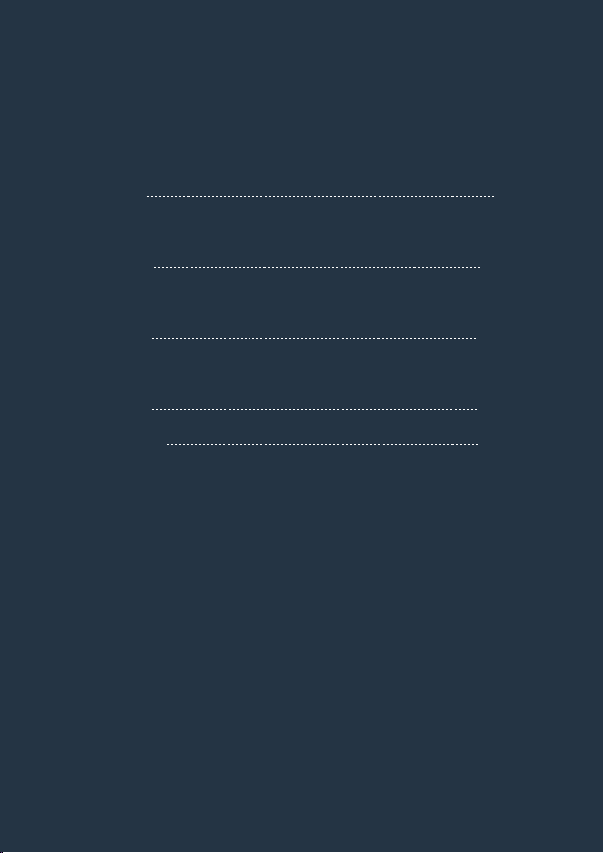
Plugging in Power
To power Ultimatte 12
Plug a standard IEC power cable into any of the two power inputs on the rear panel.
NOTE Blackmagic Ultimatte 12 is equipped with two power supplies. This means you
can connect an alternative power supply for redundancy. Ultimatte 12 will automatically
switch to the second power source if your main power source fails.
Plug power into any of the two power inputs on the main unit’s rear panel.
To control your Ultimatte 12 main unit, you will need to connect to a Smart Remote 4 control
panel. Up to 8 Ultimatte 11 or Ultimatte 12 main units can be can be controlled by a single
SmartRemote 4 control panel.
To power Smart Remote 4
Plug the included power adapter into the DC power input on the rear panel. The screw ring is
used to secure the connector to the port.
Plug the power adapter into Smart Remote 4’s power input
66Getting Started
Page 7
TIP The power adapter’s outside screw ring also serves as the negative contact,
with the positive contact being the center pin of the connector. If you want to secure a
ground connection to the chassis of your Smart Remote 4, you can attach it to the
terminal lug located next to the power input.
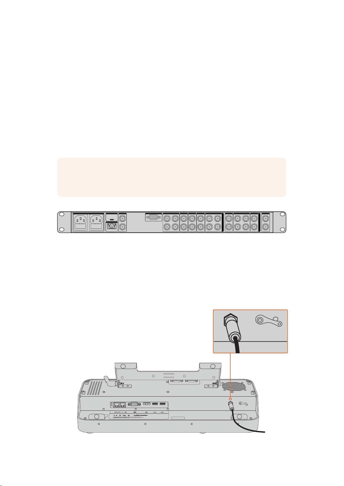
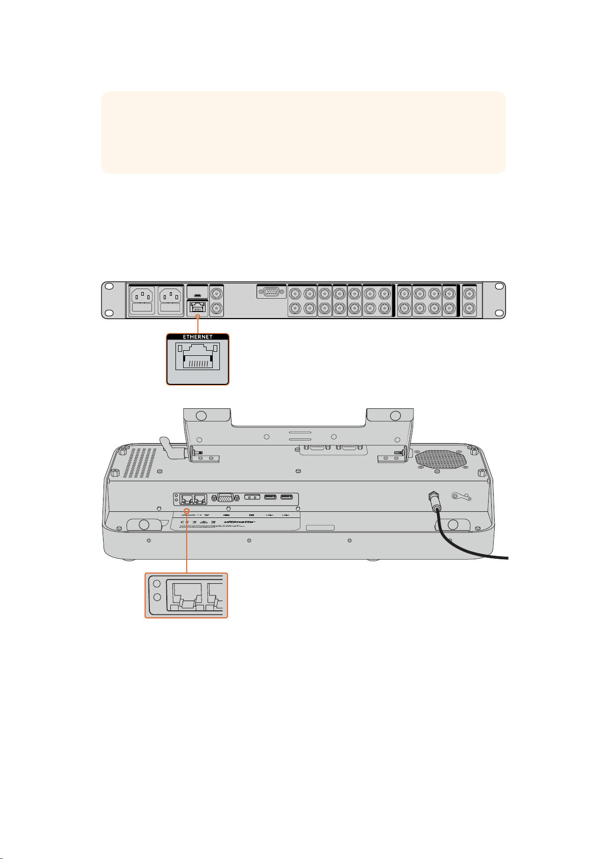
Connecting the Smart Remote 4 to your Ultimatte
Connect the Smart Remote 4 to your Ultimatte 12 via Ethernet using a standard CAT 5e or CAT
6 Ethernet cable. We recommend using a CAT 6 shielded cable as it will prevent any potential
interference from nearby equipment.
USB
AC IN G MATTE
REF FILL MATTE
ETHERNET
OUT
IN
GPIO BG FGBG MATTE
LOOPINLOOP
LOOP
IN
IN
LAYER LAYER MATTEH MATTE
LOOPINLOOP
LOOP
IN
IN
PGM
INPUTS
LOOPINLOOP
1
IN
2
121
TALENT
MONITOR
OUTPUTS
1
OUT
2
2
IN
Plug your Ultimatte main unit into the Smart Remote 4’s left side Ethernet port using a CAT6 Ethernet cable
The Ultimatte 12 main unit has a default IP address of 192.168.10.220. If you are using a new
smart remote with your Ultimatte 12, then the smart remote will automatically detect the main
unit so you won’t need to change any IP settings.
If you are connecting an Ultimatte 12 to a network that uses a different IP address, subnet mask
and router, you can change the IP settings for your Ultimatte to suit your network. Refer to the
‘connecting to a network’ section for more information.
77Getting Started
Page 8
TIP If you are adding an Ultimatte 12 to an existing system that includes Ultimatte 11,
SMART REMOTE 4
SMART REMOTE 4
MATTE
CLEAN UP
LEVEL
FOREGROUND BACKGROUND LAYER MATTE IN CONFIGURE
0% 100%
0%
MATTE
MATTE MENU
MATTE
PROCESS
SCREEN
SAMPLE
CLEAN UP
FILTERFILTER
FOREGROUND BACKGROUND LAYER MATTE IN CONFIGURE
MATTE
CUSTOM
MENUS
MONITOR
OUT
CUSTOM
MON OUT
MATTE
RESET
CURSOR POS
LAST
AUTO SCREEN
SAMPLE
PGM
OUT
FG
IN
BG
IN
COMBINED
MATTE
INTERNAL
MATTE
FILL
OUT
FUNCTIONS
MONITOR OUT
MAIN MENUS
GROUPS
ACTIVE FILE: Ultimatte
RED DENSITY
0% 100%
100%
BLUE DENSITY
0% 100%
100%
BLACK GLOSS
0% 100%
0%
MATTE DENSITY
-100% 300%
0%
REF SOURCE - FG IN
BACKING COLOR
1
2
3 4
5 6 7 8
you will need to update your Smart Remote 4 to the latest SR4 internal software.
Refer to the ‘updating your Smart Remote 4’ section for more information.
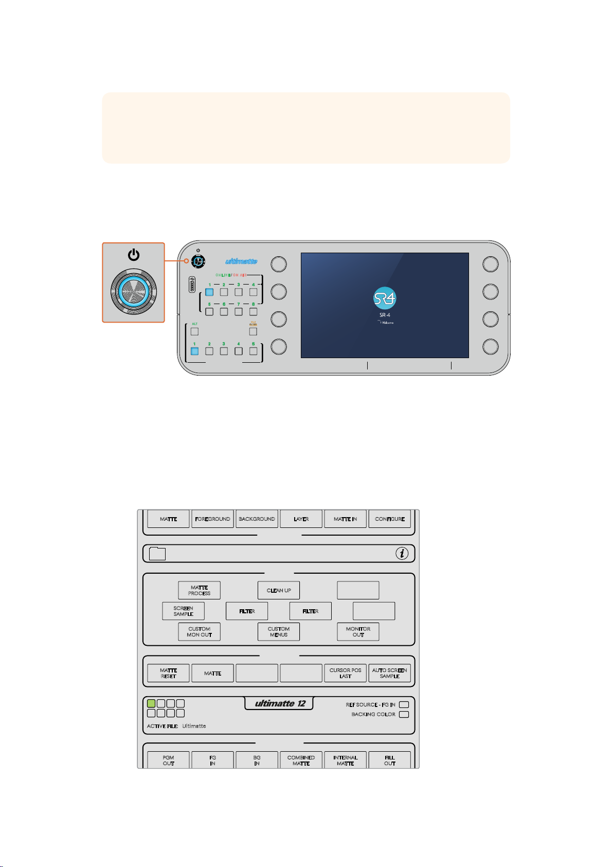
Turning On the Smart Remote 4
To turn the smart remote on, press the power button located at the top left corner of the
control panel.
ONLINE / ON AIR
1 2 3 4
UNITS
5 6 7 8
ALT
1 2 3 4 5
QUICK LOAD
QUICK SAVE
FILE
CLEAR
When power is activated, the power button will illuminate blue and the smart
remote will initiate the software start up sequence
At its heart, Smart Remote 4 is a small portable computer running the Windows® operating
system. When the start up sequence is complete, the Ultimatte control software will launch
andthe control panel will appear on the touchscreen.
The status bar near the bottom of the touchscreen will prompt you to select an Ultimatte
main unit.
SMART REMOTE 4
When the Smart Remote 4 start up sequence is complete, the Ultimatte control
software will launch and the status bar will prompt you to select an Ultimatte main unit
88Getting Started
Page 9
MATTE
MATTE MENU
MATTE
PROCESS
SCREEN
SAMPLE
CLEAN UP
FILTERFILTER
FOREGROUND BACKGROUND LAYER MATTE IN CONFIGURE
MATTE
CUSTOM
MENUS
MONITOR
OUT
CUSTOM
MON OUT
MATTE
RESET
CURSOR POS
LAST
AUTO SCREEN
SAMPLE
FUNCTIONS
MAIN MENUS
GROUPS
ACTIVE FILE: Ultimatte
BLUE DENSITY
0% 100%
100%
BLACK GLOSS
0% 100%
0%
MATTE DENSITY
-100% 300%
0%
REF SOURCE - FG IN
BACKING COLOR
1
2
3 4
5 6 7 8
MATTE
MATTE MENU
MATTE
PROCESS
SCREEN
SAMPLE
CLEAN UP
FILTERFILTER
FOREGROUND BACKGROUND LAYER MATTE IN CONFIGURE
MATTE
CUSTOM
MENUS
MONITOR
OUT
CUSTOM
MON OUT
MATTE
RESET
CURSOR POS
LAST
AUTO SCREEN
FUNCTIONS
MAIN MENUS
GROUPS
REF SOURCE - FG IN
BACKING COLOR
1
2
3 4
5 6 7 8
SMART REMOTE 4
ONLINE / ON AIR
1 2 3 4
5 6 7 8
UNITS
SMART REMOTE 4
MATTE
MATTE MENU
CLEAN UP
LEVEL
SHADOW
LEVEL
MATTE
PROCESS
SCREEN
SAMPLE
CLEAN UP
FILTERFILTER
FOREGROUND BACKGROUND LAYER MATTE IN CONFIGURE
MATTE
CUSTOM
MENUS
MONITOR
OUT
CUSTOM
MON OUT
MATTE
CURSOR POS
AUTO SCREEN
FUNCTIONS
MAIN MENUS
GROUPS
0% 100%
0%
BLUE DENSITY
BLACK GLOSS
0% 100%
0%
MATTE DENSITY
-100% 300%
0%
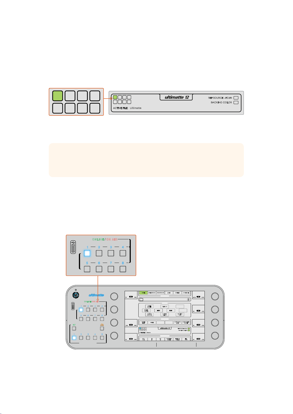
The Smart Remote 4 Status Bar
You can see all the Ultimatte units being controlled by your smart remote by glancing at the
status bar on the touchscreen. Up to 8 units can be controlled, and each unit icon will illuminate
green when identified on your network. When a unit is selected for control, the icon will
illuminate blue. For more information on how to set up and control multiple units over a network,
refer to the ‘connecting to a network’ section.
Refer to the ‘connecting to a network’ section for information about how to set
up and control multiple Ultimatte units on your network
TIP If your Ultimatte 12 is connected to the Smart Remote 4 but its unit indicator is not
illuminated in the status bar, check your IP settings are configured correctly for the main
unit and Smart Remote 4. Refer to ‘connecting to a network’ for more information.
Selecting the Ultimatte Main Unit
With the Ultimatte unit icon illuminated green in the status bar, you can now select that unit to
control. Simply press the corresponding unit button on the left side of the control panel.
When selected, the unit button will illuminate blue and the touchscreen will now reveal all the
controls for that unit.
CLEAN UP
MATTE
ONLINE / ON AIR
1 2 3 4
UNITS
5 6 7 8
ALT
1 2 3 4 5
QUICK LOAD
QUICK SAVE
FILE
CLEAR
Press a unit button to select the desired Ultimatte main unit you want to control
LEVEL
0%
0% 100%
SHADOW
LEVEL
100%
100% 200%
SHADOW
THRESHOLD
100%
0% 100%
SMART REMOTE 4
FOREGROUND BACKGROUND LAYER MATTE IN CONFIGURE
MAIN MENUS
MATTE MENU
GROUPS
MATTE
PROCESS
SCREEN
SAMPLE
CUSTOM
MON OUT
MATTE
RESET
1
1
2
3 4
5 6 7 8
ACTIVE FILE: Ultimatte
PGM
OUTFGINBGIN
CLEAN UP
FILTERFILTER
CUSTOM
MENUS
FUNCTIONS
MONITOR OUT
COMBINED
CURSOR POS
LAST
INTERNAL
MATTE
MATTE
MATTE
MONITOR
OUT
REF SOURCE - FG IN
BACKING COLOR
AUTO SCREEN
SAMPLE
FILL
OUT
MATTE DENSITY
0%
-100% 300%
BLACK GLOSS
0%
0% 100%
BLUE DENSITY
100%
0% 100%
RED DENSITY
100%
0% 100%
99Getting Started
Page 10
Connecting Video Sources and Outputs
LOOP
IN
LOOPINLOOP
IN
LOOPINLOOP
IN
LOOP
IN
LOOP
IN
LAYER LAYER MATTEH MATTE
1
2
1
2
1
2
PGM
1
2
TALENT
OUT
IN
MONITOR
LOOP
IN
INPUTS
OUTPUTS
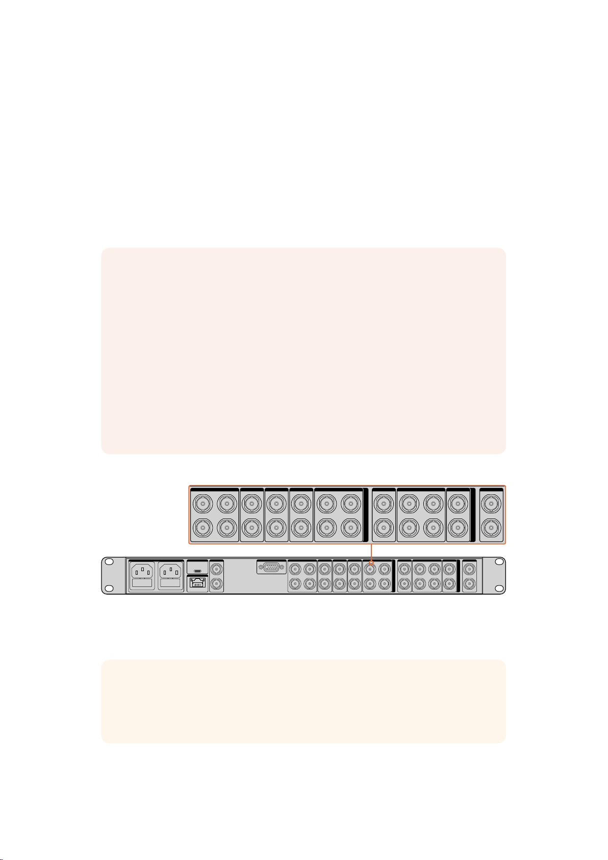
With power connected and both units running, you can now plug your SDI video sources into
the BNC inputs, and plug your switcher, monitor and recording equipment into the BNC outputs.
The SDI input sources will generally be made up of your background, foreground, mattes and
any additional layers required to create your composite. Each input has its own loop output so
you can connect each source to a monitor or recording equipment.
Ultimatte 12 has resynchronizers on each input, so you don’t need to genlock all your sources.
The foreground source provides the reference, and all other inputs will automatically lock to that
input. However, an analog reference input is provided if you want to sync all sources to an
external reference source.
NOTE The foreground input determines the video format for all other inputs.
For example, if you have 2160p59.94 video connected to the foreground input, ensure
that all of your sources have 2160p59.94 video connected to their respective inputs.
Ultimatte will detect a level A or level B 3G-SDI input automatically. The output is set to
level B by default, but you can change it to level A if needed.
To change the 3G-SDI output to level A or B:
1 Go to the ‘configure’ menu on your Smart Remote 4.
2 Tap on the ‘system’ button.
A window will appear with checkboxes for level A and Level B 3G-SDI.
3 Tap the desired level checkbox, then tap ‘apply’ to confirm the setting.
Tap ‘close’ to exit the window.
USB
AC IN G MATTE
REF FILL MATTE
ETHERNET
OUT
IN
GPIO BG FGBG MATTE
LOOPINLOOP
LAYER LAYER MATTEH MATTE
LOOP
LOOPINLOOP
LOOP
IN
IN
IN
IN
PGM
INPUTS
LOOPINLOOP
1
IN
2
121
TALENT
MONITOR
OUTPUTS
1
OUT
2
2
IN
The SDI outputs on the right side of the rear panel let you connect the final composite output to
a switcher. You can also monitor each fill and matte output, plus connect the talent output to a
monitor so the talent can see the composited output in your studio or on location.
TIP The loop outputs are helpful when making a fast assessment of all your sources
and associated mattes. For example, connecting each loop output to a multiview via an
ATEM switcher, or a Blackmagic MultiView 16 is a powerful way to monitor all your
sources simultaneously.
For more information about all the inputs and outputs on your Ultimatte, refer to the ‘connecting
sources and outputs’ section of this manual.
1010Getting Started
Page 11
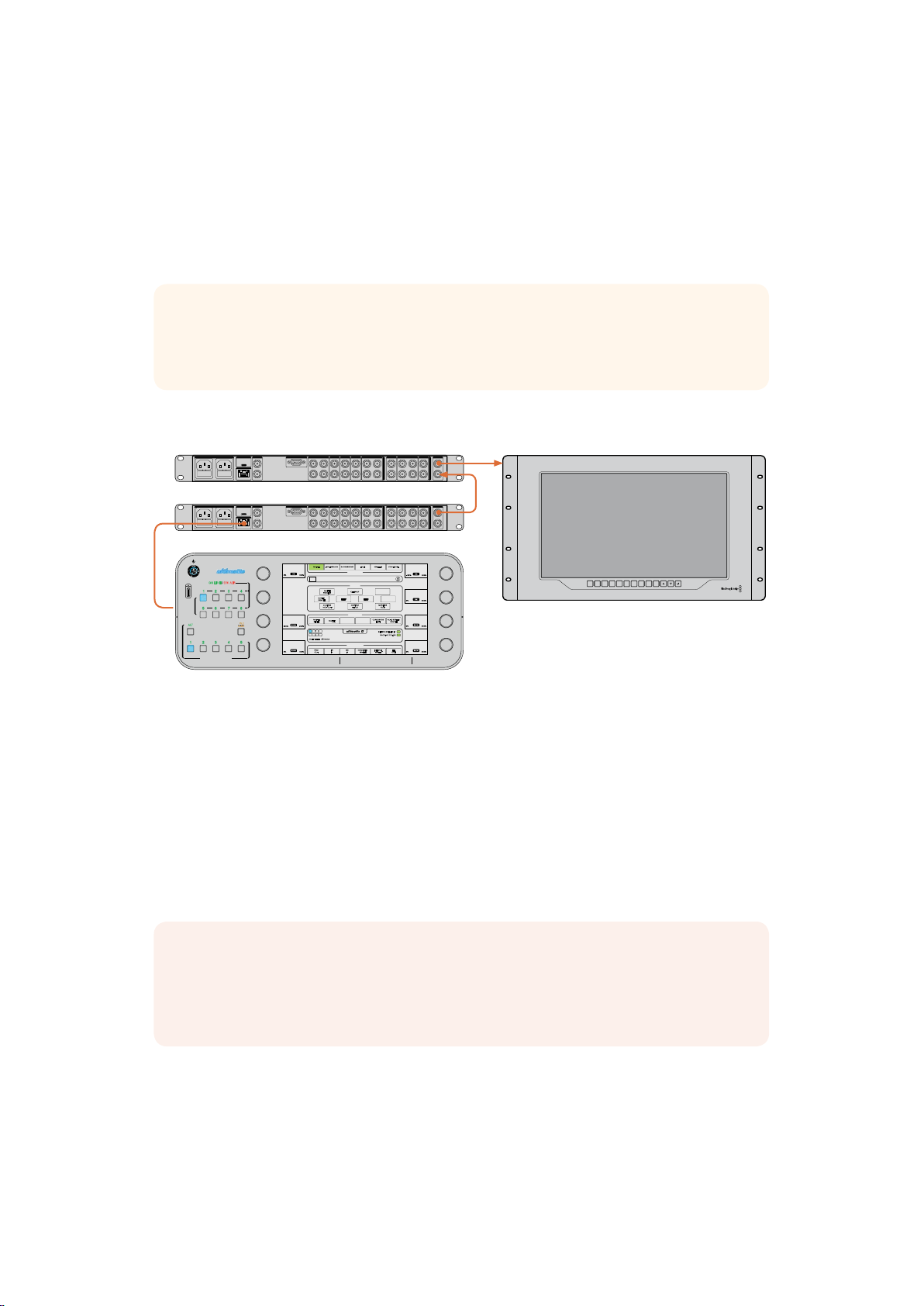
Monitor Cascade Feature
SMART REMOTE 4
The powerful monitor cascade feature lets you view the monitor output from up to 8 Ultimatte 12
units via one single unit.
8 Ultimatte 12 units can be daisy chained via their monitor inputs and outputs, with the last unit
plugged into a monitor. Then when you select any of the 8 units on your smart remote to control,
the monitor output for that particular unit can be viewed from the monitor output on the last unit.
TIP To enable the monitor cascade feature on the touchscreen control panel, tap on
the ‘info’ icon in the files and information section, and check the ‘monitor cascade’
checkbox in the ‘options’ tab.
Below is an example showing how 2 Ultimatte 12 units are daisy chained for cascade monitoring.
USB
AC IN G MATTE
ETHERNET
GPIO BG FGBG MATTE
REF FILL MATTE
OUT
IN
LOOPINLOOP
LOOPINLOOPINLOOP
LOOP
IN
IN
LAYER LAYER MATTEH MATTE
PGM
INPUTS
LOOPINLOOP
IN
IN
2
TALENT
MONITOR
OUTPUTS
12121
1
OUT
2
IN
USB
AC IN G MATTE
ETHERNET
ONLINE/ ON AIR
1 2 3 4
UNITS
5 6 7 8
QUICK LOAD
QUICK SAVE
FILE
CLEAR
ALT
1 2 3 4 5
GPIO BG FGBG MATTE
REF FILL MATTE
OUT
IN
LOOPINLOOP
CLEAN UP
MATTE
LEVEL
0%
0% 100%
SCREEN
SAMPLE
SHADOW
LEVEL
MATTE
RESET
100%
100% 200%
1
1
2
3 4
5 6 7 8
ACTIVE FILE: Ultimatte
SHADOW
THRESHOLD
PGM
100%
0% 100%
OUTFGINBGIN
SMART REMOTE 4
LAYER LAYER MATTEH MATTE
LOOPINLOOPINLOOP
IN
FOREGROUND BACKGROUND LAYER MATTE IN CONFIGURE
MATTE
PROCESS
CUSTOM
MON OUT
MATTE
LOOPINLOOP
LOOP
IN
IN
IN
MAIN MENUS
MATTE MENU
GROUPS
CLEAN UP
FILTERFILTER
CUSTOM
MONITOR
MENUS
OUT
FUNCTIONS
CURSOR POS
LAST
REF SOURCE - FG IN
BACKING COLOR
MONITOR OUT
COMBINED
INTERNAL
MATTE
MATTE
PGM
INPUTS
2
AUTO SCREEN
SAMPLE
FILL
OUT
12121
MATTE DENSITY
-100% 300%
BLACK GLOSS
0% 100%
BLUE DENSITY
0% 100%
RED DENSITY
0% 100%
TALENT
MONITOR
OUTPUTS
1
OUT
2
IN
0%
0%
100%
100%
INPUT DISP
H/V
BLUE
ZOOM PEAK
DELAY3DLUT 1
ONLY
3D
LUT 2HMARKVMARK
With cascade monitoring, you can monitor the output of the currently
active unit being controlled by your Smart Remote 4
For more information on cascade monitoring, refer to the ‘configure settings/monitor
cascade’ section.
Setting an Auto Composite using the File Clear Button
With all your inputs and outputs connected, Ultimatte 12 will perform an automatic composite.
This is a starting composite that is set by default based on all your connected sources.
Thisstarting composite can be reset at any time by pressing the ‘file clear’ button.
NOTE The file clear button will set an automatic composite with green selected as the
backing color by default. If you are using a different backing color, for example red or
blue, then you will need to set your Ultimatte to use that color. Refer to the ‘quick guide
to building a composite’ section for more information.
If your lighting is optimized and your green screen environment has been carefully set up, the
automatic composite generated by Ultimatte can be all you need to achieve the desired effects.
You can now refine the background, foreground, and layer settings if you need to, and
generally finesse your composite to make the illusion of combining the virtual and live action
even more convincing!
Please keep reading this manual for more information on how to use all the settings and
features on your Ultimatte 12.
1111Getting Started
Page 12

Connecting Sources and Outputs
Each source input used in a composite should be carefully planned, so the elements that build
your shot can be arranged into specific layers. Each source should be connected to its
determined source input so you always know where everything is, and you can manage your
composite more effectively.
SDI Inputs
Background Input
Plug the background image into the BG IN connector. This is the image you want to use as the
background for your composite.
Background Matte Input
If you want to extract a section of the background to use as a foreground element, plug the
background matte source into the BG MATTE IN connector.
TIP Refer to the next section of the manual to find more information on the different
mattes you can use, including how to extract an element from the background to
composite over the foreground using a background matte.
Garbage Matte Input
Plug a source containing an externally generated garbage matte into the G MATTE IN
connector.
Foreground Input
Plug the foreground image you want to composite over the top of the background into the
FG IN connector. The foreground image is typically the talent in front of a green screen.
Holdout Matte Input
Plug a source containing an externally generated holdout matte into the H MATTE IN connector.
Layer Input
The layer input is for any additional video or graphics you want to add to your composite.
Layer Matte Input
Similar to other matte inputs, this input lets you connect an externally generated matte so you
can precisely add the layer input source into your composite.
SDI Outputs
Below is a description of each output on your Ultimatte 12 main unit.
Source Loop Outputs
Each source input has its own dedicated loop SDI output.
Program Outputs 1 and 2
Plug a program output, marked PGM into an SDI switcher or recording deck, for example an
ATEM switcher or HyperDeck Disk Recorder.
Fill Outputs 1 and 2
Plug the fill outputs into a recording deck, and into a switcher for final compositing.
Matte Outputs 1 and 2
Plug the matte outputs into a recording deck, and into a switcher for final compositing.
The matte output includes the internal matte, plus the garbage matte and holdout matte
if enabled.
12Connecting Sources and Outputs
Page 13

Talent Out 1 and 2
The talent output lets your talent monitor the final composite so he or she can position
themselves in the frame and coordinate their actions to the composited image.
TIP The talent output has a ‘mirror’ setting that lets you flip the talent output
horizontally. Using this feature, the talent can see his or her positioning without needing
to compensate for reversed camera left and right staging. Refer to the ‘configure
settings/talent mirror’ section for more information.
Monitor Output
Plug the monitor output marked MONITOR OUT into a monitor or recording deck. This
connector isalso used for daisy chaining to other Ultimatte 12 units when using the powerful
monitor cascade feature. Refer to the ‘configure settings’ section for more information.
Monitor Input
The monitor input is important for daisy chaining to other Ultimatte 12 units when using the
powerful monitor cascade feature. Refer to the ‘configure settings’ section for more information.
What is a Matte?
Before looking at how to use all the features and settings on your Ultimatte, it’s worth
taking a moment to look at the types of mattes you can use, and how they are arranged in
your composite.
When a section of an image is intended to be composited over another image, it requires an
accompanying matte, either generated internally by Ultimatte, or supplied via an external
source. A matte is also known as an ‘alpha’, or ‘key’, and is displayed as a grayscale image.
The matte determines what will be visible in the accompanying source image that is being
composited. The source image to be composited is called the ‘fill’.
Black regions in the matte will allow those regions in the corresponding ‘fill’ image to be visible
in the composited output, and any areas that are white will be cut out, or removed, showing the
image behind it. Variations of gray means those areas of the corresponding fill image will be
partially transparent.
Types of Mattes
Different matte types are used for specific purposes, to separate areas of the corresponding
image into foreground and background elements, or to include or exclude sections of the matte
you want to keep or discard.
Below is a description of the types of mattes used.
Background Matte
The background matte is a powerful way to extract a section from the background and place it
over the foreground.
For example, you may have a virtual set as your background image. Inside the virtual set is a
row of tall marble pillars. Using a background matte that precisely matches the pillars in your
virtual set, you can extract the pillars from the background and the talent can walk behind them.
This is an excellent way to create a foreground element using the background image and keeps
the layer input free for additional foreground items. It’s important to note that elements to be
extracted from the background must be completely opaque.
13Connecting Sources and Outputs
Page 14

Matte
This is the primary matte you will be working with in your composite. This matte is derived using
the source connected to the foreground input. Typically a presenter in front of a green screen.
The matte is generated internally by analyzing the backing color in the source video and will
determine what is visible in the foreground image.
TIP Objects that obscure the backing color, either partly or completely, will be visible in
the composited image. In the matte, fully opaque black means the corresponding areas
in the fill image will be completely visible. Shades of grey means partially transparent.
Garbage Matte
A garbage matte excludes areas of a source you don’t want to include in your composite.
For example, there may be lights and gripping equipment visible around the edges of your
foreground image. If you want to mask out these unwanted areas, a garbage matte lets you do
that. Garbage mattes can be generated externally so they precisely match shapes in your
source video, and connected to the garbage matte input.
TIP A rectangular mask can be created internally using the ‘window’ controls. This can
be a great tool for creating a fast, rough garbage matte. For more information on how to
setup window masks, refer to the ’matte input settings/window’ section.
Holdout Matte
This matte is similar to a garbage matte, however, it lets you mask out areas from within the
visible foreground so they are ignored by the matte.
For example, imagine a portion of a virtual set needs to appear green in the foreground.
This will present a challenge because anything green will key out and reveal the background
underneath. A holdout matte can be created to exclude that particular area within the set, which
will prevent it from being keyed.
Layer Matte
The layer matte lets you add more foreground elements to the scene. For example, if you want
to add graphics over the top of the composite.
You can swap the layer positioning in the final composite. For example, you may want to change
the layer order during your production so the layer input appears in front of, then behind, the
talent. You can even set a transition rate so the order change is a smooth mix transition.
For more information, refer to the ‘Matte input settings/setting the layer order’ section.
1414What is a Matte?
Page 15
Controlling Ultimatte
SMART REMOTE 4
MATTE
FOREGROUND BACKGROUND LAYER MATTE IN CONFIGURE
MAIN MENUS
MATTE DENSITY
0%
MATTE
MATTE MENU
FOREGROUND BACKGROUND LAYER MATTE IN CONFIGURE
MAIN MENUS
MATTE DENSITY
-100% 300%
0%
with SmartRemote 4
CLEAN UP
MATTE
FOREGROUND BACKGROUND LAYER MATTE IN CONFIGURE
MAIN MENUS
MATTE MENU
MATTE
PROCESS
SCREEN
SAMPLE
CUSTOM
MON OUT
MATTE
RESET
1
1
2
3 4
5 6 7 8
ACTIVE FILE: Ultimatte
PGM
OUTFGINBGIN
GROUPS
CLEAN UP
CUSTOM
MENUS
FUNCTIONS
MATTE
MONITOR OUT
COMBINED
FILTERFILTER
MONITOR
OUT
CURSOR POS
LAST
REF SOURCE - FG IN
BACKING COLOR
INTERNAL
MATTE
MATTE
ONLINE / ON AIR
1 2 3 4
UNITS
5 6 7 8
ALT
1 2 3 4 5
QUICK LOAD
QUICK SAVE
CLEAR
LEVEL
0%
0% 100%
SHADOW
FILE
LEVEL
100%
100% 200%
SHADOW
THRESHOLD
100%
0% 100%
SMART REMOTE 4
All the matte generation and compositing features of your Ultimatte 12 are controlled using
theSmart Remote 4.
The controls and settings are accessed via the smart remote touchscreen, control buttons and
knobs. The settings for each soft control knob changes depending on which menu you have
selected on the touchscreen.
AUTO SCREEN
SAMPLE
FILL
OUT
MATTE DENSITY
0%
-100% 300%
BLACK GLOSS
0%
0% 100%
BLUE DENSITY
100%
0% 100%
RED DENSITY
100%
0% 100%
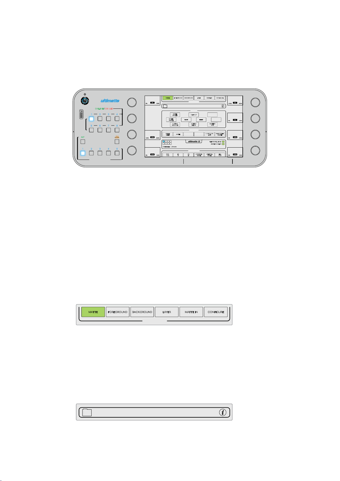
The Control Panel Layout
Touchscreen menus are displayed in sections, and although the interface can look intimidating
at first glance with all the different buttons and settings, it won’t take long before you will be
moving between settings instinctively as you build your composite.
Main Menu Buttons
Tap the menu buttons along the top of the touchscreen to select the different input sources you
want to adjust, plus select the matte for making adjustments to the primary matte, and generally
configure your Ultimatte 12.
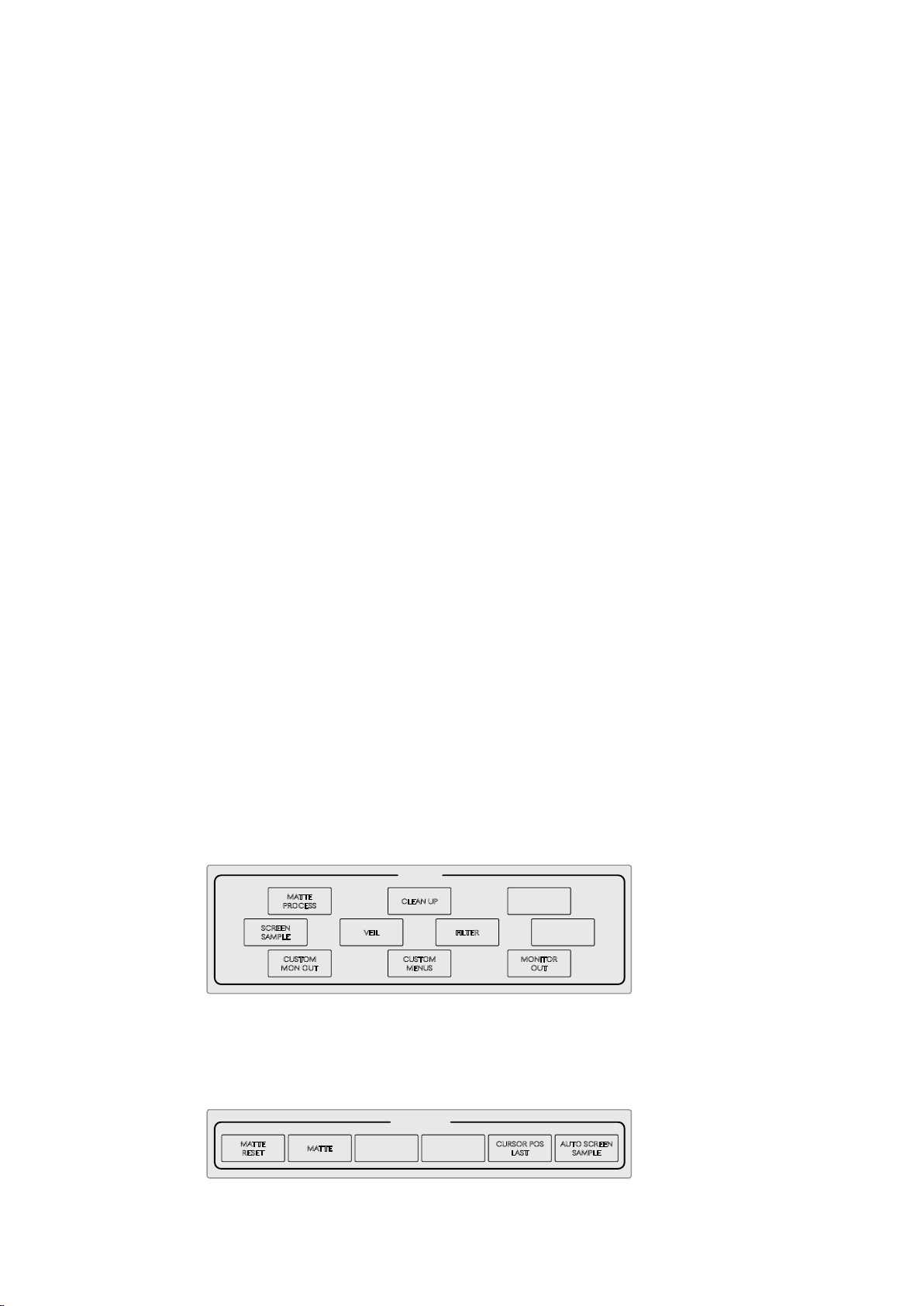
Information and File Control
This section of the interface lets you save preset files and configure certain settings for
yourUltimatte.
To save a preset file, tap on the folder icon and use the dialog box edit functions to name and
save a file. Refer to the ‘saving and loading preset files’ section for more information.
To view status information and various configuration settings for your Ultimatte and Smart
Remote 4, tap on the information icon.
1515Controlling Ultimatte with Smart remote 4
Page 16
The available information and configuration settings are described below:
MATTE
MATTE MENU
MATTE
PROCESS
SCREEN
SAMPLE
CLEAN UP
FILTERVEIL
FOREGROUND BACKGROUND LAYER MATTE IN CONFIGURE
CUSTOM
MENUS
MONITOR
OUT
CUSTOM
MON OUT
MAIN MENUS
GROUPS
BLACK GLOSS
0% 100%
0%
MATTE DENSITY
-100% 300%
0%
MATTE
MATTE MENU
MATTE
PROCESS
SCREEN
SAMPLE
CLEAN UP
FILTERVEIL
FOREGROUND BACKGROUND LAYER MATTE IN CONFIGURE
MATTE
CUSTOM
MENUS
MONITOR
OUT
CUSTOM
MON OUT
MATTE
RESET
CURSOR POS
LAST
AUTO SCREEN
SAMPLE
FUNCTIONS
MAIN MENUS
GROUPS
BLUE DENSITY
0% 100%
100%
BLACK GLOSS
0% 100%
0%
MATTE DENSITY
-100% 300%
0%
About
Displays detailed status information about your Ultimatte, including:
Model name
Software version
Video format
IP address
Subnet mask
Default gateway.
Smart Remote 4 Information is also included, such as:
Remote version
Flash version
Temperature
Fan speed
Blackmagic Design contact information should you need support.
Configuration
Provides an overview of connected SDI sources and will tell you whether they are locked or not.
Control Board Settings
Lets you customize the brightness of the Smart Remote 4’s LEDs and set the the internal
fan speed.
Options
Turns the mouse pointer on or off if you have a mouse connected to your smart remote.
Enables the monitor out cascade feature.
Groups
This section of the interface contains the majority of the setting menus. For example, if you
wanted to adjust the foreground ‘flare’ controls:
1 Tap on the ‘foreground’ main menu button to open the foreground settings.
2 Tap on the ‘Flare 1’ button in the groups section to select the flare controls.
The flare controls will now be visible on each side of the panel and you can adjust them using
the control knobs.
Functions
The functions section provides specific settings that can be selected, enabled or disabled.
For example, the reset button is located in this section if you need to restore particular settings
to their default state.
1616Controlling Ultimatte with Smart remote 4
Page 17
Status Bar
MATTE
MATTE MENU
MATTE
PROCESS
SCREEN
SAMPLE
CLEAN UP
FILTERVEIL
FOREGROUND BACKGROUND LAYER MATTE IN CONFIGURE
MATTE
CUSTOM
MENUS
MONITOR
OUT
CUSTOM
MON OUT
MATTE
RESET
CURSOR POS
LAST
AUTO SCREEN
SAMPLE
FUNCTIONS
MAIN MENUS
GROUPS
ACTIVE FILE: Ultimatte
BLUE DENSITY
0% 100%
100%
BLACK GLOSS
0% 100%
0%
MATTE DENSITY
-100% 300%
0%
REF SOURCE - FG IN
BACKING COLOR
1
2
3 4
5 6 7 8
1
MATTE
MATTE MENU
MATTE
PROCESS
SCREEN
SAMPLE
CLEAN UP
FILTERVEIL
FOREGROUND BACKGROUND LAYER MATTE IN CONFIGURE
MATTE
CUSTOM
MENUS
MONITOR
OUT
CUSTOM
MON OUT
MATTE
RESET
CURSOR POS
LAST
AUTO SCREEN
SAMPLE
PGM
OUT
FG
IN
BG
IN
COMBINED
MATTE
INTERNAL
MATTE
FILL
OUT
FUNCTIONS
MONITOR OUT
MAIN MENUS
GROUPS
ACTIVE FILE: Ultimatte
RED DENSITY
0% 100%
100%
BLUE DENSITY
0% 100%
100%
BLACK GLOSS
0% 100%
0%
MATTE DENSITY
-100% 300%
0%
REF SOURCE - FG IN
BACKING COLOR
1
2
3 4
5 6 7 8
1
You can see all the Ultimatte units being controlled by your smart remote by glancing at the
status bar on the touchscreen. Up to 8 units can be controlled, and each unit icon will illuminate
green when identified on your network. When a unit is selected for control, the icon will
illuminate blue.
The indicator for the Ultimatte unit being controlled will illuminate blue
to let you know it is the active unit
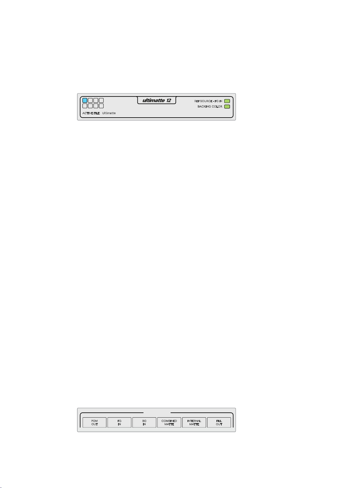
Ultimatte Main Unit Indicators
The 8 small box indicators on the left side show you which main units are connected on the
network, and which unit is currently being controlled. If tally is connected via the GPIO input,
the boxes will illuminate red when a unit is on air.
Reference Source - Foreground In
This indicator will illuminate red when a reference source is absent, and green when a reference
source is present. The reference signal can be connected via the foreground source connected
to the foreground input, or via the reference input.
Backing Color
The default backing color is green and will be reflected by this indicator. When the backing
color is changed, the indicator will also change to show the backing color being used.
Active File
When you have loaded a preset file using the information and file control section, the preset
name will be displayed in the active file area. If no preset is loaded, the active file displays the
Ultimatte default preset.
In addition, the status bar also notifies you with messages. For example, if a specific control is
currently locked and you need to enable another setting to access it, the status bar will
notify you.
Monitor Out
The soft buttons in this section of the interface will select 1 of 6 images to be displayed on a
video monitor connected to your Ultimatte’s monitor output.
The default selections are listed below.
Program Out – Final composited image.
Foreground In – Source image connected to the foreground input.
Background In – Source image connected to the background input.
Combined Matte View – Internal Matte + Garbage Matte + Holdout Matte.
Internal Matte View – Screen matte only.
Fill Out - Foreground image with spill removed, colorizers added, and the screen color
suppressed to black.
1717Controlling Ultimatte with Smart remote 4
Page 18

Connecting to a network
Setting the IP Address for Ultimatte 12
Your Ultimatte 12 main unit is shipped with a default IP address of 192.168.10.220 but you can
change this address if you want to connect to a network. This is also important when sharing
multiple Ultimatte units on your network and controlling them using a single Smart Remote 4.
To change the IP address for an Ultimatte main unit, you will first need to download and install
the latest Blackmagic Ultimatte Setup software from the Blackmagic Design support center at
www.blackmagicdesign.com/support. For installation information refer to the ‘updating the
internal software’ section in this manual.
After installation:
1 Connect the desired Ultimatte 12 main unit to your computer via USB.
2 Launch Blackmagic Ultimatte Setup.
3 Click on the unit icon for your Ultimatte to open the setup settings.
4 In the ‘configure’ tab, enter the IP address, subnet mask and gateway settings.
5 Click ‘save’ to confirm the settings.
Repeat the same process for each main unit you want to control. The subnet mask and gateway
should match your network settings and stay the same between all units, but make sure each
unit has its own unique IP address.
Setting the IP Address for your Smart Remote 4
Now that each Ultimatte main unit has a new IP address, you will need to configure the IP
address of your Smart Remote 4 so you can control the main units on your network.
To set the IP address on your Smart Remote 4:
1 Reveal the Windows desktop by tapping on the info icon in the Smart Remote
touchscreen information and file control section. Now tap on the ‘options’ settings and
tap exit to desktop.
2 Navigate to the Windows network settings.
3 In the Ethernet related settings, select ‘change adapter options’.
4 Double tap on the ‘Ultimatte’ network to open the Ultimatte status window.
5 Tap on ‘properties’.
6 In the properties window, double tap on ‘internet protocol version 4 (TCP/IPv4) to open
its setting properties.
7 Select the ‘obtain an IP address automatically’ setting to let your Smart Remote find its
own IP address to join the network you are connected to. Or if you want to enter the
IP address, subnet mask and default gateway settings, select ‘use the following
IP address’ and set it manually.
8 Tap ‘OK’ to confirm the settings.
Double tap on the SR4 smart remote software icon to return to the touchscreen control panel.
18Connecting to a network
Page 19
Setting the Main Unit’s IP Address on Smart Remote 4
ONLINE / ON AIR
QUICK LOAD
QUICK SAVE
ALT
1 2 3 4
5 6 7 8
UNITS
FILE
CLEAR
SMART REMOTE 4
1 2 3 4 5
MATTE
MATTE MENU
CLEAN UP
LEVEL
SHADOW
LEVEL
SHADOW
THRESHOLD
MATTE
PROCESS
SCREEN
SAMPLE
CLEAN UP
FILTERFILTER
FOREGROUND BACKGROUND LAYER MATTE IN CONFIGURE
MATTE
CUSTOM
MENUS
MONITOR
OUT
CUSTOM
MON OUT
MATTE
RESET
CURSOR POS
LAST
AUTO SCREEN
SAMPLE
PGM
OUT
FG
IN
BG
IN
COMBINED
MATTE
INTERNAL
MATTE
FILL
OUT
FUNCTIONS
MONITOR OUT
MAIN MENUS
GROUPS
ACTIVE FILE: Ultimatte
0% 100%
100%
100% 200%
100%
0% 100%
0%
RED DENSITY
0% 100%
100%
BLUE DENSITY
0% 100%
100%
BLACK GLOSS
0% 100%
0%
MATTE DENSITY
-100% 300%
0%
REF SOURCE - FG IN
BACKING COLOR
1
2
3 4
5 6 7 8
1
With your Smart Remote 4 now ready to control your Ultimatte main units, you will need to tell
the smart remote where they are by setting their unit IP addresses in the Smart Remote 4
control panel.
To do this:
1 In the status bar, tap on a unit ID number to open the unit IP configuration window.
2 In the ‘model’ column, tap on the desired unit number’s drop down menu and select
Ultimatte 12.
3 Now set the IP address for the desired main unit using the software keyboard.
4 Tap ‘apply’ to confirm the settings.
If you look at the status bar, you will now see that unit number illuminated green. This means
theunit is online and ready to be controlled.
Repeat the same steps to set the IP address for each unit on your network.
Ultimatte Compositing Workflow
Now that you’re familiar with using the Smart Remote 4 to control your Ultimatte 12, and have
pressed the file clear button to set an automatic starting composite, you can start finessing
and refining your composite using Ultimatte’s features and settings.
As you refine your composite, it is helpful to move back and forth between monitoring the
combined matte view and the program output so you can optimize the matte, plus see how it
is working in the final composite.
When adjusting controls, it’s worth mentioning that you can restore any control back to its
default state by double tapping the respective control.
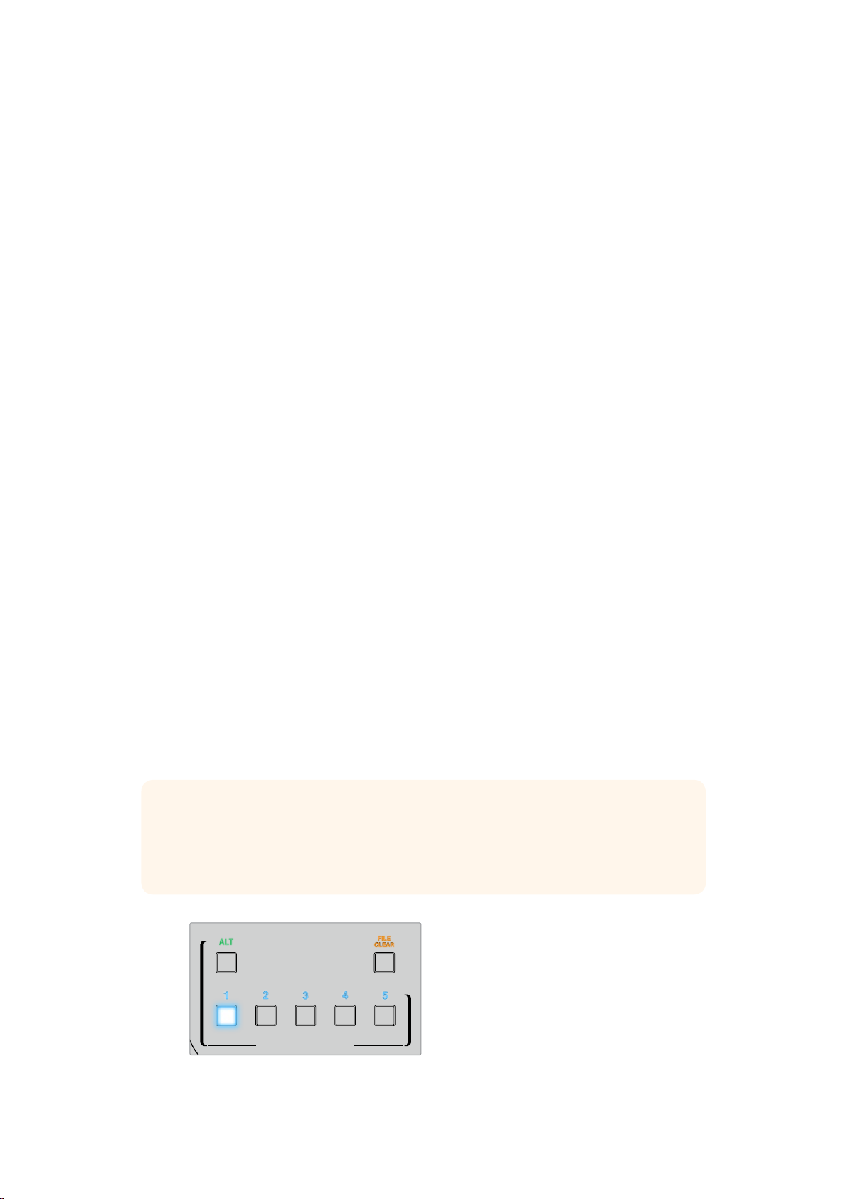
You can also save your workflow to quick save points. As you change settings and make
improvements, it’s helpful to switch between save points to compare and assess what has
changed in order to achieve the best possible settings.
To save a quick save, hold down the ‘alt’ button and press a quick save button. To load a quick
save, simply press the desired quick save button.
TIP The quick save and quick load points are stored in volatile memory so they are
available only until you power down your Ultimatte. To store settings permanently,
you can save a file that can be loaded again after power cycling. Refer to the ‘saving
and loading preset files’ section for more information.
Use the quick load and quick save buttons to make fast
comparisons between composites throughout your workflow
191919Ultimatte Compositing Workflow
Page 20

Quick Guide to Building a Composite
This is a basic introduction to performing a fast composite with Ultimatte 12 and
Smart Remote 4.
With all sources connected to the main unit, the first step is to make sure the backing color is
correctly set. The default backing is color is green, but you can set it to red or blue, depending
on which color you are using on set.
If you are using a green screen, you don’t need to change the backing color as green is already
set by default. Pressing the ‘file clear’ button will perform an automatic composite and generate
a matte from your green screen.
TIP An automatic composite will also take place when power cycling your Ultimatte 12.
Setting the Foreground Backing Color
The backing color defines the color Ultimatte will use to generate the matte. Typically, the color
used for most screens for compositing is green, and this is why green is the default backing
color. However, there are occasions on set where red or blue may be a better choice based on
the color of the foreground objects. In this event, you will need to tell Ultimatte to use a different
backing color.
To set the backing color:
1 Tap the ‘configure’ menu button to open the configure settings.
2 In the functions area, tap one of the red, green or blue backing buttons to select your
desired backing color. You will now see the backing color indicator in the status bar
change to the corresponding backing color.
When the backing color is set, Ultimatte will perform an automatic composite and you will see
the results on the program output. In the monitor out buttons, tap the button marked ‘PGM OUT’
to select the program output and the image will appear on the monitor connected to the
monitor output.
Setting Screen Correction
Screen correction can be helpful if there are strong variations in your backing screen, or the
lighting on the backing screen is uneven.
If your camera is static and you can remove all the foreground objects from the scene, you can
perform a screen correction. This shows Ultimatte what the screen looks like by itself, and then
once all elements are replaced, Ultimatte can then analyze what has changed in the foreground
and will generate an optimized matte. This can help tidy up any areas that are not behaving in
your matte.
2020Quick Guide to Building a Composite
Page 21

To perform a screen correction:
1 Remove all the foreground elements in your scene so only the backing screen is visible.
2 Select the ‘matte’ settings from the main menu buttons.
3 In the ‘groups’ section, select ‘matte process’.
4 Press the ‘screen capture’ button. This stores a snapshot of the green screen which
Ultimatte uses to generate the screen correction.
5 Now replace all the foreground elements into your scene.
6 Press the ‘screen correct’ button.
Your Ultimatte will now analyse the foreground elements against the captured image and
determine the optimized matte.
NOTE When using the screen correction feature, it’s best to perform this function once
the camera is set and in place, because once the camera moves, screen correction will
no longer be effective and you will need to reapply the screen correction.
Setting the Matte Density
If the matte needs some refinement, the first step is to adjust the matte density. This improves
the black areas of the matte so it is opaque. Any gray areas inside the black matte will cause
the background to show through the foreground in those areas.
To adjust the matte density:
1 Tap the ‘matte’ menu button to open the matte settings.
2 Rotate the matte density control knob counterclockwise to decrease the matte density
until you start seeing the gray areas inside the black silhouette.
3 Now increase the matte density setting until the gray areas are no longer visible.
Be sure to stop adjusting as soon as the gray areas disappear. This is because the least
amount of adjustment will result in a more convincing composite. This is true for most
controls when refining your composite.
You should now see a near perfect composite on the program output. Now you can use the
additional matte settings, foreground, background, and layer settings to refine your composite.
2121Quick Guide to Building a Composite
Page 22

Changing Settings
Adjusting Matte Controls
Matte Density
When refining your composite, the matte density setting should always be adjusted first.
This setting strengthens the general opacity of the black areas of the matte, preventing areas
of the background to show through the foreground.
To adjust the matte density:
1 Select ‘matte’ in the main menu buttons.
2 In the ‘monitor out’ section, press ‘combined matte’. You will see the foreground subject
appear as a black silhouette on a white field.
3 Using the control knob, decrease the matte density until you see details within
the black start to become gray. Now increase the setting until the gray areas
change to black.
4 Select the program output in the monitor out settings.
Any show through that was present prior to adjusting matte density should now be almost,
or completely, gone.
Black Gloss
Sometimes there may be dark areas of your foreground that have bright highlights which are
reflecting the backing color. These highlights can appear gray in your matte, which will cause
those areas in your foreground image to become transparent in your composite. The black
gloss setting helps to remove these areas from the matte.
Increase the black gloss setting while observing the combined matte output until these
reflective areas are no longer visible in the matte.
TIP If the matte is already opaque and there are no highlights showing, it’s worth
decreasing the black gloss level until you see the highlights, then increasing and
stopping as soon as they are no longer visible. This is because the lowest setting that
can be achieved will result in the cleanest, most convincing composite. This is true for
many of the matte controls.
Red, Green and Blue Density
As matte density and black gloss settings are increased, dark edges can form around
foreground objects. To compensate, the density of the color channels surrounding the edge
ofthe foreground objects can be adjusted.
For example, if your backing color is green, the colors available to adjust are red and blue.
If your backing color is red, the adjustable colors are green and blue. Adjusting these fine color
density controls can help clean up dark edges.
222222Changing Settings
Page 23

Matte Reset
Tap this button to restore all the matte controls that affect the foreground elements to their
default settings. The matte settings that affect the green screen area, for example clean up
andveil settings, will not be changed.
Clean Up Settings
Imperfections in your blue or green screen such as scuff marks, seams, unwanted shadows,
electronic noise, and screen residue are visually the same as fine details in the foreground.
As a result, these imperfections will also be visible in your final composited picture.
Adjusting the following controls will electronically clean your screen, but at the expense of the
finest detail on the edges of the foreground elements. We recommend using these controls
sparingly as they can produce a hard edged, cutout look to the final composited image.
TIP Switch your monitor view between combined matte and program out to determine
the best settings.
To adjust the clean up settings:
1 While viewing combined matte, the screen area is represented as white. Adjust the
clean up controls so that the screen area is as close to white as possible without
eliminating important detail.
2 View program out to make sure that you haven’t eliminated too much of the fine detail.
The goal is to set these controls to the lowest possible value while ensuring the final picture is
not missing subtle details such as fine wisps of hair, shadows, or reflections.
TIP Don’t get too focused on getting a perfect clean matte. Some imperfections like
slight scuff marks or electronic noise might actually look appropriate in the final
composited image, particularly if the background scene is a computer generated,
pristine image.
The clean up settings are interactive. Therefore, increasing one might allow you to decrease
one or more of the others. You’ll notice the greatest effect in the green screen area, but you
might also see a slight effect on the foreground elements.
Clean Up Level
Increase or decrease to reduce or eliminate imperfections in the blue or green screen.
Clean Up Dark Recover
Use this control to recover shadows or edge detail on darker colored elements that
were reduced or eliminated by clean up level.
Clean Up Light Recover
Increase this setting to recover edge detail on lighter colored elements that were
reduced or eliminated by clean up level.
Clean Up Strength
Use this control to add more strength to clean up light recover.
Clean Up Reset
Press the clean up reset soft button to restore all clean up controls to their
default settings.
232323Changing Settings
Page 24

Veil Settings
At this point while you are optimizing your matte, you may notice a fine white haze over your
final composited image. The haze can sometimes appear as a general haze, or localized in
patches corresponding to the screen area of the foreground source.
The white haze is known as ‘veil’ and you can minimize it by adjusting the veil settings.
Master Veil
Increase or decrease to remove neutral colored veil over your program or fill output.
Red, Green, and Blue Veil
Adjust these controls respectively when you see a colored haze over the
program output.
TIP Switch your monitor view between the fill output and program out to determine
thebest veil settings.
NOTE Veiling can become more pronounced over the course of the day as your blue
or green floor gets dirtier or dustier. We recommend wearing slippers when not
shooting if crew and talent are walking on the blue or green screen. Repainting of the
screen may become necessary to remove permanent dirt and marks.
Shadow Level and Shadow Threshold
If you want your shadows in the foreground source to be more or less pronounced in your final
composite, increase or decrease the shadow level. The shadow threshold setting is used to
help separate unwanted dark screen areas from shadows.
Matte Process/Screen Correction
Depending on the conditions of your green screen, the backing color may not be consistent
which can reduce the effectiveness of the matte. If you are seeing noise or artifacts in your
matte that you can’t solve using the general matte settings, and you have access to an image
ofjust the green screen without foreground objects, then you can use screen correction to
improve the matte.
To set screen correction:
1 Remove all the foreground objects in your scene so only the green screen is visible.
2 Tap the ‘screen capture’ button so Ultimatte can store a snapshot of the green screen.
3 Now replace all the foreground objects in your scene.
4 Tap the ‘screen correct’ button.
You should now see a general improvement in your matte and final composite.
NOTE Screen correction only works with static camera shots. This feature is the best
choice for improving areas in the backing screen, and clean up controls can be used as
a last resort if areas still need improvement.
242424Changing Settings
Page 25

Matte Correct Horizontal Size
‘Matte correct H size’ analyzes all horizontal matte transitions, based on the size selected in
number of pixels, and applies the appropriate amount of correction to the horizontal transitions
which may need modification.
Unlike regular matte sizing, which slightly reduces the overall size of the matte, the ‘matte
correct’ control selectively corrects only transitions which are not optimally corrected.
The ‘matte correct H size’ setting indicates the number of pixels within which the system will
analyze every transition. When the size is set to 0, no correction is applied.
Matte Correct Vertical Size
‘Matte correct V size’ analyzes all vertical matte transitions, based on the size selected in
number of lines, and applies the appropriate amount of correction to the vertical transitions
which need modification.
The ‘matte correct V size’ display indicates the number of lines within which the system will
analyze every transition. When the size is set to 0, no correction is applied.
Screen Sample
When Ultimatte creates the matte for the foreground, it automatically samples the backing color
in the foreground image to achieve the best matte. If varying shades remain visible in the matte,
you can set your Ultimatte to use single or dual sampling which can help achieve better results.
Single Sampling
Single sampling lets you manually select a single area of the foreground green screen with a
small box cursor. Ultimatte then assesses the color in that region and optimizes the sampling
ofthe backing color using that region.
To use single sampling:
1 Go to the screen sample settings in the ‘matte’ menu.
2 Tap on the wall cursor position button. Your view will change to the foreground input
and a small box cursor will appear on the screen.
3 Adjust the cursor horizontal and vertical position using the control knobs to move the
cursor to a spot on the wall near important detail. This can often be hair. Be sure to
avoid areas that contain detail that you want to retain.
4 Tap on the ‘sample wall’ button to save these screen values as your new reference.
Your view will switch back to the monitor out setting you were last using.
Dual Sampling
Depending on the lighting conditions and your green screen, the floor area may appear at a
different luminance or shade of green compared to the walls which may affect the quality of
your matte when using the default auto sampling or manual single sampling.
To help Ultimatte achieve the best matte, you can select dual sampling and position two
separate cursors.
To use dual sampling:
1 Go to the screen sample settings in the ‘matte’ menu and tap on ‘dual sampling’
toenable dual sampling mode.
2 Tap on the wall cursor position button. Your view will change to the foreground input
and a small box cursor will appear on the screen.
3 Adjust the cursor horizontal and vertical position using the control knobs to move the
cursor to a spot on the wall near important detail. This can often be hair. Be sure to
avoid areas that contain detail that you want to retain.
252525Changing Settings
Page 26

4 Tap ‘sample wall’. Notice that ‘floor cursor position’ is now enabled and the floor cursor
position is automatically available for you to adjust. Make your desired changes to the
cursor position.
TIP For the best results, select an area on the floor where you see lighting
glare or veiling, and avoid shadow areas that you want to retain in the matte.
5 Tap ‘sample floor’. Your selection will save these screen values as your new reference
and the view will switch back to the monitor out setting you were last using.
Filter
The filter settings let you remove ringing artifacts that may appear in the transition edges,
plus provides noise reduction and noise generation settings to help blend foreground and
background elements together.
4:2:2 Correction level
In a Y,Cb,Cr 4:2:2 video image, objects with high contrast and sharp transitions can exhibit
a small edge artifact when used for green screen compositing. This is due to the reduced
bandwidth of the Cb and Cr color difference channels.
For example, a dark colored foreground object with sharp transitions shot against a bright
green screen will show an overshoot and an undershoot at the transitions. This is known as
ringing. These ringing artifacts are shades of black and white and will be treated as foreground
objects when processed, similar to gray strands of hair. When the green screen color is
removed and replaced by a dark background, a dark foreground object will show bright gray
edges at the transitions.
The 4:2:2 correction feature eliminates or reduces the ringing artifacts. No foreground object
detail is lost in this process.
4:2:2 correction is set to 100% by default. To make an adjustment, decrease the setting while
monitoring the program output until you notice the ringing artifact appear in the composite,
then gradually increase until it is no longer visible.
Noise Reduction/Generation
All video recorded using a video camera will contain a minor level of noise in the image.
When composited with pristine, noise free graphics generated by a computer, the difference
between sources can be noticeable.
To help blend elements, Ultimatte has noise reduction and noise generation settings that let
you clean noise from the foreground, and add noise to the clean areas of your composite.
For example, noise can be generated in the background or layer source, or areas of the
foreground that have been masked by a garbage matte.
There are two types of noise reduction. Median, and average.
To reduce noise:
1 Toggle between the average and median noise reduction types by tapping the
selection button on the left side of the functions section.
2 Now tap the corresponding setting next to the selection button to set a noise reduction
level. Tap multiple times to gradually increase the level. There are 4 levels of noise
reduction to choose from.
262626Changing Settings
Page 27

To generate noise:
1 Tap the ‘noise cursor’ button in the functions section to enable the cursor on the
foreground source.
2 Using the cursor position controls, place the cursor on an area of the foreground that
displays the most prominent noise.
3 Tap the ‘noise select’ button.
4 Tap the ‘noise gen’ button to enable noise generation.
5 Increase or decrease the amount of noise generation using the ‘noise gen level’ control.
Matte Reset
Tapping the matte reset button restores all matte controls, including matte density, black gloss,
color density, and shadow settings to their default settings. These default settings could be
factory set or user set values. For more information on customizing your Ultimatte, refer to the
‘saving and loading preset files’ section.
NOTE Matte reset does not sample the backing for new reference color values.
The current values are used to recalculate spill suppression with any adjusted
background settings.
Matte Button
Tap this button to disable or enable the matte generation and flare settings. The default setting
of this button is ‘enabled’.
Cursor Position Last
When this button is enabled, the cursor will return to the horizontal and vertical positions where
it was last used. This mode is helpful when studio cameras are mounted on robotics systems
and could be programmed to go to the same starting position, thus allowing the same exact
sampling locations to be used again. When you save a preset file, cursor location is also saved.
When disabled, the location of the cursor will always return to a default horizontal and vertical
position toward the top left hand corner of the image, regardless of the previously used
sampling location.
Auto Screen Sample
Auto screen sample is the default method of scanning, analyzing, and determining reference
backing color levels. Using this method, the matte signal is analyzed to detect the most
predominant highest level, which will correspond to the brightest and purest area of the
backing. Auto screen sample will also be performed during all of the functions listed below:
Main unit power up, system reset, backing color select, file clear, and ALT file clear.
Adjusting Foreground Flare Controls
Your Ultimatte 12 automatically analyzes the backing color reflecting onto foreground objects
and removes the effect of the bounce color in the final composite. This is called spill
suppression. The process of spill suppression can affect certain colors in the foreground.
Thecolors affected will vary depending on the backing color you are using. If you need to
makecolor adjustments to restore the original color of foreground elements, the results of
spillsuppression can be adjusted using the flare controls.
272727Changing Settings
Page 28

Flare 1 Settings
Cool
Restores cooler colors, such as blue, green and cyan.
Skin Tone
Restores the color of natural skin tones that may have been changed by spill
suppression.
Light Warm
When advanced flare is enabled, this setting recovers lighter, warmer colors,
such as red, yellow and orange. This setting interacts with the skin tones setting.
Black, Gray and White Balance
Use this setting to color correct the spill suppression in the tonal regions of the
foreground, such as the shadows, mid tones and highlights.
Flare Level
When advanced flare controls are enabled, this setting adjusts the overall amount
of spill suppression for certain foreground colors.
Holdout Matte Flare Button
When a holdout matte is used to stop the compositing process in portions of the
foreground scene, spill suppression on the foreground becomes slightly more
complicated. In some situations, removing spill suppression from the entire scene
would result in a more convincing look. In other situations, no spill suppression in the
holdout matte area would be the best choice.
When holdout matte flare is disabled, spill suppression is not performed in
the holdout matte region. When enabled, spill suppression is removed from the entire
foreground scene.
Flare 2 Settings
Flare Correct Horizontal or Vertical Size
Flare correction analyzes the spill suppression in the transition areas and lets you make
subtle corrections. For example, neutralizing small color discrepancies, or luminance
variations that may be affecting fine edges in the transition area.
You can adjust the size of the area around the pixels of interest that Ultimatte will use to
analyze the spill suppression. This area is defined via pixel width and line height. When
the size is set to 0, no flare correction is applied.
Dark Warm
When advanced flare is enabled, this control can help to restore brown colors,
forgreen screen, and purple colors, for blue screen. This control interacts with skin
tones settings.
Flare Reset
Tap this button to reset all flare controls to their default settings, depending on the backing
color selected.
Advanced Flare
If you are adding Ultimatte 12 to an existing system using Ultimatte 11 units and you want to
maintain a consistent look between them, you can disable the advanced flare features in
Ultimatte 12 and use standard flare processing. This sets the flare controls and spill suppression
in Ultimatte 12 to match the standard features in Ultimatte 11 units which will maintain
consistency in the image when switching between multiple units.
282828Changing Settings
Page 29

Adjusting Foreground Ambiance Controls
To make a composite more convincing, it is important that the foreground subject fits seamlessly
into its new background environment. The ‘ambiance’ feature in Ultimatte 12 analyzes the colors
of the background and foreground layers, and automatically adds subtle color influences from
the background into the foreground layer. This feature is enabled by default.
The ambiance controls also allow you to set the amount of influence that the background has
on the foreground layer, and finesse the color balance.
Making Foreground Ambiance Changes
1 Select ‘foreground’ in the main menu buttons.
2 In the ‘groups’ section, press ‘ambiance 1’ or ‘ambiance 2’ to access these menus.
Ambiance reset
Tap the ‘ambiance reset’ button to reset all ambiance controls to their default settings.
Ambiance
Tap this button to disable or enable the ambiance feature. The default setting of this
button is ‘enabled’.
Ambiance 1 Settings
The ambiance controls will add very subtle amounts of color from the background, simulating
reflected ambient light from the background source.
Ambiance Level Red, Green, Blue
Adjust these settings to increase or decrease effects of the red, green and blue
components of the background ambiance that will influence the foreground
color levels.
Ambiance Level Master
This setting adjusts the overall level of the ambiance that will influence the foreground
color levels. When adjusting this control, the relative difference between the ambiance
red, green, and blue components will be maintained.
Ambiance Strength
This setting adjusts the strength of the ambiance that will influence the main area of the
foreground subject, compared to the transition areas from the foreground subject to the
background scene. At its maximum setting, the ambiance will have full influence on the
main area as well as the transition region, while at the minimum setting, the ambiance
will have no influence in the main area while having a stronger influence in the
transition regions.
Direct Light Mix
This setting controls the proportion by which the foreground subject will be influenced
by the ambiance colors and user adjustable direct lighting. At the maximum setting,
the foreground subject is influenced entirely by the direct light controls, and at its
minimum setting, the foreground subject is influenced entirely by the ambiance colors.
Vertical Blur
This setting determines the number of averaged lines in the background used in
ambiance calculations. Depending on the background scene, reducing this control
could introduce streaking on the foreground layer.
Ambiance 2 Settings
The direct light controls will make more aggressive changes to the foreground image,
simulating light that is directly from a position in the front of the foreground subject.
Direct Light Red, Green, Blue
Adjust these settings to increase or decrease the impact of red, green and blue
components of the direct light that will influence the foreground color levels.
292929Changing Settings
Page 30

Adjusting Brightness, Color, Contrast and Saturation
As you build your composite, you will likely want to make adjustments to the luminance,
color, contrast, and saturation levels for your sources which can help improve your composite.
For example, if the foreground, background and layer elements seem to differ in levels
compared to accompanying composited layers, you can perform an independent color
adjustment using the master controls for each source. All the same luminance, color balance,
contrast, and saturation settings are available for each source.
White Level Master
If a source seems too bright or too dark for the adjoining scene in the composite, adjust the
white level control to alter the brightness of the source rather than adjusting the original input
source level. Altering the level at the input source, for example the camera exposure, can
adversely affect the generation of the matte signal.
The default setting of the white level control is neutral at 100%. The range of the control is from
0% to 200%. The main unit will clip the output so the signal cannot exceed standard limits.
When adjusting the white level master, the relative difference between the white level red,
green, and blue components will be maintained.
Black Level Master
The master black control adjusts the level of black in the source image without altering the
white level. Adjusting the black level can often produce a more convincing composite image,
if the black levels in the background scene differ from those in the foreground.
When adjusting the black level master, the relative difference between the black level red, green,
and blue components will be maintained. Ultimatte 12 will clip black levels at zero so they do not
exceed standard broadcast limits.
Contrast Master
The contrast master control adjusts the overall contrast level of the source in the composite
without affecting the quality of the composite. For example, if the lighting contrast in the
foreground scene does not match that of the background scene, adjusting this control may
produce a more convincing composite image.
The contrast setting does not affect the strength of black and white levels, but only changes
thecontrast of the gamma, or mid level gain, in the source image.
When adjusting the contrast master, the relative difference between the contrast red, green,
and blue components will be maintained.
Saturation Master
The saturation master control adjusts the saturation level of the selected source colors without
affecting the generation of the matte signal. For example, if the saturation of the colors in the
background scene does not appear to match the saturation of the foreground colors, adjusting
this control may produce a more convincing composite.
The saturation master control can completely remove all color from the source image and
produce a monochrome, or black and white, foreground composited with a color
background image.
When adjusting the saturation master, the relative difference between the saturation red,
green, and blue components will be maintained.
303030Changing Settings
Page 31

Advanced Contrast Crossover Master
When the ‘advanced contrast’ button is enabled in the functions section, contrast adjustment
characteristics will acquire an “S” shape curve. The crossover point of the “S” shape can be
moved by the source ‘contrast crossover’ master control.
Fade Control
A fade control is available for the foreground, background and layer sources. This setting lets
you fade the foreground or layer source, if enabled, until it is lo longer visible.
When the primary matte is disabled in the matte settings, you can use this feature to fade
between the foreground source and background source to line up props or set items in the
foreground with the background source.
When adjusting the fade or fade-mix control from 0% to 100%, the selected source will gradually
fade until no longer visible.
Color Correcting Black and White Levels
The ‘black/white level’ menu for each background, foreground and layer source lets you make
specific color corrections to the black level and white level. By adjusting the respective red,
green and blue color correction controls you can adjust each respective color level without
altering the overall gain.
TIP Any adjustments to color for the black and white level will only occur after the
matte signal generation and will not affect the source.
Adjusting Color Contrast and Saturation
The ‘contrast/saturation’ menu provides controls to adjust contrast for each color channel in the
selected source. Adjusting the contrast control for each channel will increase or decrease the
amount of contrast in the gamma, or mid level gain.
When the ‘advanced contrast’ button is enabled in the functions section, contrast adjustment
characteristics will acquire an “S” shape curve. The crossover point of the “S” shape can then
be moved by the source ‘contrast crossover’ control. This gives you greater control over how
contrast affects the gamma tonal region.
Color Reset
If at any time you want to restore the color correction back to its default state, simply tap the
color reset button in the functions section.
Source Freeze Button
If you are working with still graphics as your sources, this feature allows for greater flexibility.
You can take a still image from each source by tapping the respective ‘freeze’ button in the
functions section. This stores a still frame in temporary memory which you can use as
the source.
The freeze feature can be helpful if you have limited playback equipment. For example, you can
save a still from a playback source graphic, then on the same playback deck, load a different
source and plug it into a different source input on your Ultimatte. This effectively doubles the
amount of sources you can use with your playback equipment.
313131Changing Settings
Page 32

Additional Background Settings
Background Filter
In many situations, particularly with computer generated backgrounds, the graphics will appear
too sharp compared to the foreground subjects. Sometimes, this sharpness can cause aliasing
artifacts if the antialiasing filters are not set properly in the background rendering system.
Advancing the background filter control will gradually apply a horizontal low pass filter to the
background scene, minimizing aliasing artifacts.
Background Gradient
Enabling this button will replace the background video with an internally generated horizontal
gradient signal. This gradient signal can be used to better demonstrate the impact of
background color controls on the background image.
Test Signal
This setting lets you use a colored field as the background in the final composite.
Additional Layer Settings
Test Signal
This setting lets you use a colored field as the layer source in the final composite.
Layer Input
Enabling this function allows the layer elements to be added to the composite scene.
Layer Input Realistic/Linear/Additive
This function selects between three modes of combining the layer input elements with the
foreground objects and the background scene in the composite image.
Realistic
Most accurate method of combining colored transparent and semi transparent layer
elements, as well as opaque layer elements, with the foreground objects and the
background scene.
NOTE When using a layer source graphic in realistic layer mode with semi
transparent objects, the image source background needs to be 100% white. The
RGB elements in the source layer should not be premultiplied by its matte. All
feathering of transition regions along edges of the matte should be within the
boundaries of the layer elements. For example, make sure feathered edges do not
extend into the white backing region of the source image.
Linear
Traditional method of combining opaque layer elements with the foreground objects
and the background scene in the composite image. This method will not produce
accurate results with transparent colored layer elements. This method should be
selected if the layer elements are not premultiplied.
Additive
Traditional method of combining opaque layer elements with the foreground objects
and the background scene in the composite image. This method will not produce
accurate results with transparent colored layer elements and should be selected if the
layer elements are premultiplied.
323232Changing Settings
Page 33

TIP Pressing the ‘file clear’ button will not change the layer input mode.
Matte Input Settings
Blackmagic Ultimatte 12 can accept 4 different matte inputs, each assigned to a specific function.
These 4 matte inputs are:
Background matte
Garbage matte
Holdout matte
Layer matte
Background Matte
The background matte is associated with certain elements in the background scene that need
to be treated as their own layer. By converting these background elements into layer elements,
they can be moved in the layering order in front of the foreground objects. These background
elements that are converted to layer elements can only be opaque elements.
Garbage Matte
The garbage matte is associated with the boundaries of the foreground screen. It is used to
artificially extend the screen area, so that the background scene can be added in these areas.
The garbage matte should have a large soft transition area, from black to white, so that the
garbage matte blends better with the real screen area.
If foreground objects enter these soft transition areas of the garbage matte, these objects will
gradually become transparent and mixed with the background scene until they are fully
faded out.
In an alternate process, Blackmagic Ultimatte 12 can gradually apply the garbage matte clean
up function in the soft transition areas so that the foreground objects can still enter these
transition areas without becoming transparent.
Holdout Matte
The holdout matte is associated with elements of foreground objects which have similar colors
as the screen color. The holdout matte can be used to prevent these portions of foreground
object areas with similar color as the screen from becoming partially or fully transparent.
Additionally, the holdout matte can be used to retain or remove the foreground object colors
that are similar to the screen color.
Layer Matte
The layer matte is associated with the ‘layer in’ elements. The layer matte is used to determine
the opacity of the corresponding ‘layer in’ source. The layer elements associated with the layer
matte could be opaque or can have varying levels of transparency with different colors.
Window
The window setting lets you create internally generated mattes that can be set with rectangular
only proportions. Enable window by tapping the ‘window’ button, then set the input source you
want to apply the window to by tapping on the respective matte button in the functions section
of the touchscreen.
333333Changing Settings
Page 34

Adjust the positioning of the window edges using the following controls:
Window Position Top, Bottom, Left and Right
These knobs adjust the position of the top, bottom, left and right edges of the window.
The default position is beyond the edge of the frame. As it is dialed in, the edge moves
into the frame and goes all the way to the opposite position of the frame.
Window Softness Top, Bottom, Left and Right
Sometimes you may want to reduce the harshness of a window edge in the garbage
matte. To do this, increase the softness control for the window edge you want to adjust.
The default position is beyond the edge of the frame. As it is dialed in, the edge moves
into the frame and goes all the way to the opposite position of the frame.
Transition Rate
This control sets the rate, in number of frames, by which the objects in the background scene,
defined by the background matte and the layer input elements, will move in front of or behind
each other in the composited image.
When the transition rate is set to 0, the changes in the layering order will be an abrupt cut.
When the rate is increased, the transition will be a smooth mix dissolve. The maximum transition
rate is 120 frames.
The transitions are initiated by selecting one of up to six different layering orders defined in the
functions section.
Setting the Layer Order
In the functions section you will see buttons that indicate the layer order. These buttons
determine the order of how the foreground source, background source, and the layer source
elements are arranged in your composite. The buttons available will depend on which mattes
you have enabled.
The first name in a button is the top element in the layering order, and the last name is bottom
element. For example, you’ll notice that the background is always the bottom element in
the scene.
When both background matte elements and layer source elements are used, the
6 possible combinations are:
FG / LY IN / BG LY / BG
Foreground source as the top layer, followed by the layer source elements, followed by
the background layer elements separated from the background source, then followed
by the background source.
LY IN / FG / BG LY / BG
The layer source is the top layer, followed by the foreground source, followed by the
background layer separated from the background source, then followed by the
background source.
LY IN / BG LY / FG / BG
The layer source is the top layer, followed by the background layer elements separated
from the background source, followed by the foreground objects, then followed by the
background source.
BG LY / LY IN / FG / BG
The background layer elements separated from the background source are the top
layer, followed by the layer source, followed by the foreground source, then followed by
the background source.
BG LY / FG / LY IN / BG
In this combination, the background layer elements separated from the background
source are the top layer, followed by the foreground source, followed by the layer
source, then followed by the background source.
343434Changing Settings
Page 35

FG / BG LY / LY IN / BG
In this combination, the foreground source is the top layer, followed by the background
layer elements separated from the background source, followed by the layer source,
then followed by the background source.
When only the background layer is used via a background matte, the 2 possible combinations are:
FG / BG LY / BG
The foreground source is the top layer, followed by the background layer elements
separated from the background source, then followed by the background source.
BG LY / FG / BG
In this combination, the background layer elements separated from the background
source are in the top layer, followed by the foreground source, then followed by the
background source.
When only the layer input is used, the 2 possible combinations are:
FG / LY IN / BG
The foreground source is the top layer, followed by the layer source, then followed
bythe background source.
LY IN / FG / BG
In this combination, the layer source is in the top layer, followed by the foreground
source, then followed by the background source.
Configure Settings
Inputs
The inputs menu gives you access to the timing controls if you need to delay the foreground
input to be synced with the background signal and to make subtle timing corrections to a
source input signal.
Frame Delay Foreground Input
This control will set the number of frame delays to the foreground input. The control
range is from 0 frames to 7 Frames.
In a 4:2:2 signal, the relative timing samples between luma and the chroma, or Y and UV
respectively, are well defined. However, some cameras might have some amount of relative
luma or chroma timing error. When viewed on a monitor as red, green or blue only, the image
will look like an ‘embossed’ picture. This timing error will cause unnatural transitions and off
color edges.
If there are no adjustments in the camera to correct the timing, Ultimatte 12’s inputs menu gives
you access to the timing controls if you need to make subtle timing corrections to a source
input signal.
Foreground Input U Position
This control will only adjust the U timing relative to Y in sub pixel values.
The maximum range of adjustment is +/- 2 pixels.
Foreground Input V Position
This control will only adjust the V timing relative to Y in sub pixel values.
The maximum range of adjustment is +/- 2 pixels.
Foreground Input UV Position
This control will adjust both the U and V timing relative to Y in sub pixel values.
Therelative difference between U and V will be maintained. The maximum range
ofadjustment is +/- 2 pixels.
353535Changing Settings
Page 36

Outputs
The output configuration settings lets you customize the appearance of the outputs and route
certain outputs to help your workflow. For example, setting the talent output to mirror, or routing
the monitor output to the program output.
You can also enable the powerful cascade monitoring feature which lets you view the program
output for multiple Ultimatte 12 units via one single unit as soon as you select a unit to control
on your Smart Remote 4.
Talent Highlight Level
This control adjusts the amount of highlight applied to the image viewed on the talent
output areas where background mattes, garbage mattes, holdout mattes and layer
mattes are used.
Matte Out Level
Internal to the unit, the matte signal is set so that fully opaque foreground objects are at
0% black and peak backing areas are at 100% white. The matte out level of 100% white
is set at 940 for a 10-bit output. Similarly, 0% black is set at 64.
NOTE The ‘matte out invert’ function will invert the polarity of the matte out.
The matte out level adjusts the level of the matte out from the white end. This control
can lower the matte out level to 0% or push it into the legal ceiling.
Monitor to Program
In most situations, it is advantageous and safe not to be able to switch the program
output to other views. However, there are times when the program out view needs
tobe changed from the composited image to another view. For example, the matte
view. For these few instances, it is possible to route the monitor output to the
program output.
When ‘monitor to program’ is enabled, the program output will show the same view
selections made in the monitor output. Disabling monitor to program will return the
program output to its previous setting.
Fill Linear Mix Correct
If the system you are using to combine the matte and fill outputs does not have an
‘additive mix’ capability, for example linear mix only, the composite image can have
dark edges due to a second processing of the processed foreground image. Enabling
the setting marked ‘Fill Lin Mix Cor’ will minimize potential artifacts caused by the
second processing of the foreground image. Use this setting when you are sending the
matte and fill to an external device for final mixing, for example a broadcast switcher.
Talent Mirror
Selecting this option will horizontally mirror the program image viewed on the
talent output.
The talent monitor output is used for the foreground subjects on the set to see
themselves inserted in the new background scene. By providing the capability to
horizontally mirror the viewed image, the talent can have a more natural feedback
whenseeing themselves on the monitor.
Monitor to Talent
When ‘monitor to talent’ is enabled, the talent output will show the same view
selections made in the monitor output. Disabling the monitor to talent will return the
talent output view to its previous setting.
363636Changing Settings
Page 37

Monitor Cascade
The monitor cascade feature can be accessed from the ‘information’ symbol on the
right side of the menu name section of the Smart Remote 4. You can find the setting
under the ‘options’ tab.
When the monitor cascade feature is disabled, the monitor output will be the view
selected by the monitor out options. For a single Blackmagic Ultimatte 12 unit, the
monitor output can be connected to a video monitor directly. Typically, if there are
multiple Blackmagic Ultimatte 12 units, the monitor output for each unit can be
connected to a routing switcher for monitoring multiple outputs.
Alternately, with multiple Blackmagic Ultimatte 12 units, they can be daisy chained via
their monitor inputs and outputs, with the last unit plugged into a monitor. Then when
you select a unit on the Smart Remote to control, the monitor output for that unit can be
viewed on that monitor. This is an efficient and powerful way to monitor the output from
up to 8 Ultimatte 12 units via one single unit.
To connect 4 units for cascade monitoring:
1 Connect the first unit’s monitor output to the monitor input of the second unit.
2 Connect the monitor output of the second unit to the monitor input of the third unit.
3 Connect the monitor output of the third unit to the monitor input of the fourth unit.
4 Connect the monitor output of the fourth unit to a monitor.
When the monitor cascade feature is enabled, the viewed image on the video monitor
will be of the unit that is selected by the Smart Remote 4 as the currently active unit.
When the unit selection is changed, the image viewed on the video monitor will change
to the monitor out of the selected unit.
Matte Out Invert
Enabling this function will invert the polarity of the matte out signal.
On Air Settings
The on air settings let you enable on air indicators for the status bar, and set your Ultimatte to
lock its controls when the unit is on air.
NOTE These controls only work when tally signals are connected to the GPIO
input and properly configured from the external tally generator.
On Air
When this button is enabled, the unit indicator in the Smart Remote status bar will
illuminate red when on air. The unit identification number above its selection button will
also illuminate red.
On Air Lock
When enabled, the on air lock feature will lock all the controls for the unit currently on
air. This helps to prevent any accidental changes to a unit that is live on air.
GPI and Tally Settings
These settings enable or disable tally signals when connected to an external GPI and tally
interface. Tally lets you monitor on air indicators so you know when an Ultimatte unit is currently
on air. GPI inputs and outputs let you trigger Ultimatte preset files as GPI events, similar in
nature to loading and running macros.
373737Changing Settings
Page 38

GPIO MENU
The GPI inputs allow external devices to trigger saved setup files in each input in a predetermined order. The maximum number of events is defined by the number of GPI inputs,
therefore the number of events you can use is 5.
It is also possible for the main unit to trigger events in other devices using the GPI output. This
triggering can be done manually, or upon loading a file if the GPI output was saved as part of
that file.
CONTROL KNOBS
GPI OUT Delay Frames
This control sets the delay, in number of frames, between triggering the event and the
execution of the GPI output switch closure. The maximum delay is 120 Frames.
GPI Functions Buttons
GPI Output Save
In order to initiate a GPI output upon loading a file, the appropriate instructions must be
saved as part of that file. When ‘GPI out save’ is selected, the instructions to trigger a
GPI output will become part of the current workspace settings. When the current
workspace settings are saved as a setup file, the instructions to trigger the GPI output
are saved with this file.
When the saved file, which includes the triggering instructions, is loaded into the
current workspace, the triggering instructions will initiate the proper GPI
output sequence.
GPI Out Low/High
Pressing this button toggles the GPI output state between low and high.
GPI Out
This provides a programmable state output, whose width and level are dependent on
the GPI out low/high setting and GPI out delay adjustment.
GPI Setup Menu
From the GPI setup menu, you can choose GPI files from the list of previously saved setup files
and load them into each GPI input. You can can step through each file to verify that the selected
files were the correct ones, and that the sequence by which these files were listed was correct.
If needed, you can edit each GPI list by removing, adding, or inserting any number of files.
GPI 1 to 5
These windows allows the user to set up the files in the order by which they will be
loaded when triggered by the signal connected to each respective GPI input.
Add
With each press, this button will add the highlighted file in the files list to the selected
GPI events list.
Remove
Press this button to remove a highlighted file from the selected GPI events list.
Remove All
This button will remove all the files from the selected GPI events list.
Step
Press this button to move down through the highlighted file selection and automatically
load the selected file into the current work space. Any file on the GPI events list can
be highlighted and loaded in the current work space by touching the corresponding
file name.
383838Changing Settings
Page 39

Reset
Pressing this button will select the top file from the GPI files list without loading the first
file. The first file will be loaded when the first GPI pulse is detected.
GPI Input Enable
This checkbox enables or disables individual GPI inputs separately based on the
setting of the GPI input select control.
GPI High Enable
Enables the software to detect either low to high or high to low transitions of the
GPI inputs.
The GPI inputs are triggered by the logic level of the input signal, not by the transition
edges. If GPI high enable is checked, the selected input will be triggered by a high
logic state. If GPI high is not checked, the selected input will be triggered by a low
logic state.
GPI IN Delay
This is a delay between detecting a GPI input and that of actual execution of the GPI
list. The GPI input delay can be set at different values for each input. The maximum
delay is 120 Frames.
Close
Selecting this button will close the window and exit the GPI setup menu.
Setting Up a GPI Event List
To set up an event list, preset files must be previously created and saved. Refer to the ‘saving
and loading preset files’ section form more information.
1 Tap the ‘configure’ menu button to go to configuration settings and select ‘GPI setup’
inthe groups section. The GPI setup window will be displayed.
2 From the tabs, select a GPI number from 1 to 5 to be used. If the selected GPI number
was used before, the event list will show the previously selected files. The existing
event list can be edited by removing, adding or inserting files. Alternately, select
‘remove all’ to remove all the files from the event list.
3 Select the file to be added to the event list. When selected, the file will be highlighted.
4 Press the ‘add’ button to add the file to the event list.
5 To add more files to the event list, repeat steps 3 and 4.
When the event list is complete, press ‘reset’ to move the pointer to the beginning of the event
list. Adjust GPI input delay if necessary. This is the delay, in frames, when loading the files from
the time the GPI pulse is received.
1 For high GPI input logic state, select the ‘GPI high enable’ checkbox. Leave deselected
if using a low logic state.
2 Enable GPI by tapping the GPI input enable checkbox.
3 Repeat these steps for each GPI input.
To edit an existing events list:
1 Tap the GPI event number to be edited.
2 Select a file to be deleted by tapping the file name on the display and tapping the
‘remove’ button.
3 To insert a new file into the event list, tap the file below the area in the list you want
to insert the new file. Now tap the ‘insert’ button.
4 When editing is completed, tap ‘reset’ to select the beginning file of the event list,
thentap ‘close’ to exit the GPI setup window.
393939Changing Settings
Page 40

GPIO Pinout
The female GPIO connector on your Ultimatte 12’s rear panel is a DE-15 connector. If you want
to build a cable for your own custom GPI and tally solution, a pinout chart is provided below.
GPIO PIN CONFIGURATION
Signal Input Pins Return Output Pins and Ground Pin
1 = GPI 0 6 = GPI 0 R
2 = GPI 1 7 = GPI 1 R
3 = GPI 2 8 = GPI 2 R
4 = GPI 3 9 = GPI 3 R
5 = GPI 4 10 = GPI 4 R
11 = Tally 12 = Tally R
13 = GPO 14 = GPO R
15 = GND
Monitor Out Settings
This selection will show all the viewing options available. The button name will be changed to
‘return’ which you can press to go back to the previous menu.
Monitor Highlight Level Control
This control adjusts the amount of highlight applied to the image viewed on the monitor output in
the areas where background mattes, garbage mattes, holdout mattes and layer mattes are used.
Monitor Setting Buttons
Matte View Range
The quality of images viewed on video monitors depends on the monitor’s brightness and
contrast setup. In many situations, the detail information in the very dark and very bright
portions of an image is sacrificed so that the rest of the image can have a more pleasant look.
The levels in a matte image cover the whole brightness gamut and most of the matte controls
are adjusted while observing matte levels near the darkest or the brightest end.
For this reason, it is difficult to adjust the matte accurately while looking at a monitor and
observing the darkest and brightest portions of the images.
Enabling the ‘matte view range’ function will raise the black level and reduce the white level of
the matte signal so that detail information in the blackest and whitest sections of the matte can
be viewed accurately on a monitor.
Reducing the range of the matte on the monitor output has no effect on any internal processing
or the signal levels of the matte out.
404040Changing Settings
Page 41

Matte View Invert
When combined matte view or internal matte view is selected as the monitor output, the matte
polarity can be reversed by the matte view invert function.
Monitor Out RGB
When selected, the monitor output will show all three color channels of the image viewed.
Monitor Out Red, Green and Blue
All three color channels can also be viewed independently. When the respective color channel
button is enabled, the monitor output will only show that particular color channel as a black and
white image. This can be helpful to spot noise, which is predominantly in the blue channel.
Custom Monitor Output Menu
The monitor out section of the Smart Remote 4 touchscreen provides 6 soft buttons which
switch the view on Ultimatte 12’s monitor output. These 6 soft buttons can be customized using
the ‘custom monitor out’ settings.
The first two soft buttons in the functions area of the touchscreen are labeled ‘standard’ and
‘inputs’. These let you set the labels of the buttons to the standard default Ultimatte monitor
output buttons, or you can match the buttons to the respective inputs. When inputs is selected,
you can easily monitor every source by pressing the respective input button.
Below is the configuration for each setting:
Standard
PGM Out
FG In
BG In
Combined Matte
Internal Matte
Fill Out
Inputs
BG In
Layer In
BG Matte In
Garbage Matte In
Holdout Matte In
Layer Matte In
You can also create up to 4 custom monitor out buttons. These can be set to show your favorite
views in the order of your choosing.
414141Changing Settings
Page 42

To configure a custom monitor output button:
1 In the ‘matte’ settings, tap on the ‘custom monitor out’ soft button in the groups Section.
2 Tap on the ‘configure’ soft button in the groups section.
3 In the dialog box, tap on any of the tabs labeled MONITOR OUT 1, 2, 3, and 4.
4 From the drop down menus, choose which of the following potential monitor outputs
you would like to assign to each of the buttons.
Program
FG In
BG In
Combined matte
Internal matte
Fill Out
Layer In
Background matte in
Garbage Matte In
Holdout Matte In
Layer matte in
Processed L M. Layer matte with adjustments applied.
Processed H M. Holdout matte with adjustments applied.
Processed G M. Garbage matte with adjustments applied.
Processed B M. Background matte with adjustments applied.
Screen correction capture. Image captured and used for screen correction function.
NOTE You do not necessarily need to assign a function to each button.
If ‘none’ is chosen, that button will simply appear blank.
5 Tap on ‘apply’ to save your choices.
To load a custom monitor configuration, tap on ‘custom monitor out’ in the groups
section, and then tap on one of the custom monitor buttons.
424242Changing Settings
Page 43

Saving and Loading Preset Files
Touching the folder symbol in the files and information section will open the files window which
gives access to all file management functions. Additionally, an on screen keyboard will appear
under the files window so you can enter file names. If you want to use an external keyboard,
you can plug in a USB keyboard via the USB ports on the Smart Remote 4.
To save a file:
1 If the new file name is a modification of an existing one, select that file name from the
list by highlighting it.
2 Touch the display in the filename box inside the files window. The prompter will appear.
3 Using the on screen keyboard, or an external keyboard, make the desired file
name changes.
4 If a completely new name will be added, press the backspace key on the keyboard
to erase the existing file name. Alternately, touching and moving a finger or a stylus
across the file name will highlight the name so that it can be over written.
5 Using the on screen keyboard, or an external keyboard, type the desired file name.
6 Press the ‘save’ button inside the files window. The status bar will display ‘saving’
until the process is completed. The new name will appear in the saved files list.
7 Press the close button to exit the files window.
To load a saved file:
1 From the saved files list, touch the file name to be loaded. The name will be
highlighted, and will be displayed in the filename box.
2 If the timing settings need to be loaded as part of the selected file, select the
‘with timing’ checkbox.
3 Press the load button to load the selected file into the current settings.
4 The selected file name will appear in the status bar as the ‘active file’.
5 Press the close button to exit the files window.
When a file is saved, all setup parameters are saved in it, including system timing settings.
When these timing setting are loaded, the system will use these settings to adjust its timing.
The process of adjusting the system timing will cause interruptions to the output video signals.
In most studio setups, once the entire system timing is adjusted, it does not change. Therefore,
once Blackmagic Ultimatte 12’s timing is set, there is no need to adjust it in day to day
operations.
When loading a file, if the saved timing settings are ignored, your Blackmagic Ultimatte 12
will maintain its current timing setup, and the output video signals will not be interrupted.
The process of loading or ignoring the saved timing settings is controlled by the checkbox,
named ‘With Timing’, next to the load button.
If the ‘with timing’ checkbox is not checked, then the selected file will not change the system
timing when loaded. After loading the file, the checkbox will be cleared.
4343Saving and Loading Preset Files
Page 44

To delete a file
1 From the saved files list, touch the file name to be deleted. The name will be
highlighted and will appear in the filename box.
2 Press the delete button to remove the selected file from the files list.
3 A prompt will ask for you to confirm the action. Select ‘yes’ to delete, or ‘no’ to cancel.
4 Repeat the process to delete other files.
5 Press the close button to exit the files window.
To rename a file
1 If the new file name is a modification of an existing one, select that file name from the
list by highlighting it. The selected file will appear in the filename box.
2 Touch the display in the filename box inside the files window. The prompter will appear.
3 Using the on screen Keyboard, or an external keyboard, make the desired file
name changes.
4 Press the rename button inside the files window. The button will display ‘renaming’, until
the process is completed. The new name will replace the old one in the saved files list.
5 Press the close button to exit the files window.
Assigning a File
This process assigns additional uses to a saved file. A saved file can be assigned to:
Custom Power Up
On standard power up, Ultimatte 12 will be set to factory default setting. If a different power up
setting is needed, a saved file with these settings can be used as a custom power up default.
The ‘custom power up enabled’ box must be checked in order to use the selected file settings
as power up defaults.
User Default
When the file clear button on your Smart Remote 4 is pressed, most of the controls and buttons
of Blackmagic Ultimatte 12 are set to default settings. If an alternate set of default settings is
desired, a saved file with these settings can be used as a user default file. Pressing ‘ALT file
clear’ will use the assigned file to set the custom default settings.
Quick Save
The quick save files are temporary files easily accessed from the Smart Remote 4. At any time,
a setup can be stored as a quick file, and then recalled when needed directly from the
dedicated buttons on the Smart Remote 4. Additionally, any of the saved files in the system can
be loaded into any one of the 5 quick files by assigning the selected file to the desired quick
save location number.
To assign a file:
1 From the saved files list, select the file name to be assigned. The name will be
highlighted and will appear in the filename box.
2 From the ‘assign to’ drop down box, select the assignment for the highlighted file.
3 Repeat steps 1 and 2 for additional assignments.
4 If needed, check the ‘custom power up enable’ box.
5 Press the close button to exit the files window.
4444Saving and Loading Preset Files
Page 45

Customizing the Menus
You can change the assignment of the Smart Remote 4 control knobs and buttons in the
‘configure/custom menus’ settings.
To set a custom menu:
1 Go to the configure settings menu.
2 Tap the ‘custom menus’ button.
3 Tap on one of the 4 custom menu presets you want to set.
4 A new ‘configure’ button will appear just above the custom menu preset buttons.
Tap this ‘configure’ button. The custom menu setup dialog box will appear.
The control knob functions are in the left side column, and you can set a function from that
column to each of the 8 slots on the right side column. The 8 slots correspond to the control
knobs as follows:
Item 1 = Top left control.
Item 2 = Left second control down.
Item 3 = Left third control down.
Item 4 = Left bottom control.
Item 5 = Top right control.
Item 6 = Right second control down.
Item 7 = Right third control down.
Item 8 = Right bottom control.
To assign functions to each control knob:
1 From the ‘knobs’ list, scroll up and down the list of functions and select a function
from the list.
2 Press the right arrow icon in the middle column that corresponds to the desired slot.
You will see the name of the selected control appear in the blank slot.
TIP If you change your mind and want to assign a different function to that slot,
simply press the left arrow to remove that function form the slot and assign a
different function.
3 Repeat steps 1 and 2 as you progress through all the slots to assign your custom
functions to each control knob.
4 Tap on the ‘buttons’ tab to assign the buttons. Follow the same procedure as shown
above to set the buttons controls.
5 When you are happy with your selections, tap ‘apply’.
You will now see all your customized controls on the touchscreen.
If you are moving through other menus and want to return to your custom menus, you can
enable them by tapping ‘custom menus’ in the groups section, then tapping on the desired
custom menu button. You will now see all the controls and functions buttons change back to
your custom selection.
4545Customizing the Menus
Page 46

Updating the Internal Software
From time to time Blackmagic Design will release new software for your Ultimatte 12 and
SmartRemote 4, with updated features and settings.
To update your Ultimatte 12, first download the latest Blackmagic Ultimatte Setup software
from the Blackmagic Design support center at www.blackmagicdesign.com/support.
Before installing any software, you will need administrator privileges. It is also a good idea
to uninstall any previous versions of Blackmagic Ultimatte Setup software present on
your computer.
Installing Ultimatte 12 Setup Software on Mac OS
1 Open the “Blackmagic Ultimatte” folder from the disc or downloaded disk image
and launch the Blackmagic Ultimatte installer software.
2 Click ‘continue’, ‘agree’ and ‘install’ buttons and the software will be installed on
your system.
Installing Ultimatte 12 Setup Software on Windows
1 Open the “Blackmagic Ultimatte” folder and launch the Blackmagic Ultimatte
installer software.
2 Click ‘continue’, ‘agree’ and ‘install’ buttons and the software will be installed
onyour system.
Updating your Ultimatte 12 Main Unit
Blackmagic Ultimatte Setup will check your Ultimatte main unit’s internal software and will ask
if you wish to update if you have a newer version installed on your computer.
Always update the Ultimatte Smart Remote 4 and Ultimatte main units at the same time so they
are all running the latest version of Blackmagic Ultimatte software.
To perform an update;
1 Connect your Ultimatte 12 to the computer via USB-C.
2 Launch Blackmagic Ultimatte Setup and click on the Ultimatte unit icon to open the
setup settings for the main unit.
3 Click on the ‘about’ tab. If your Ultimatte 12’s internal software requires updating, you
will be prompted with a message asking if you would like to update the software. Click
‘update’ to initiate the update process, which may take a few minutes. It’s important you
don’t unplug the power from your Ultimatte 12 main unit during the software update.
Updating your Smart Remote 4
If you have SR4 software 1.0.5 or earlier installed, you will need to first uninstall the SR4
software from your smart remote using the built in Ultimatte maintenance tool.
NOTE If you have previously installed Smart Remote 4 software using the Ultimatte
Smart Remote Setup installer from the Blackmagic Design support center, then you can
skip this uninstall process and go straight to the ‘installing Ultimatte Smart Remote
Setup’ section.
4646Updating Smart Remote 4
Page 47

Uninstalling Ultimatte SR4 v1.0.5
The first step to uninstalling the SR4 software is to ensure the application is not running.
To quit the SR4 software:
1 Tap on the ‘info’ icon in the smart remote 4 file control section in the control panel.
MATTE MENU
2 In the ‘options’ tab, tap on the ‘exit to desktop’ button.
3 Now that the desktop is visible, tap on the ‘up’ arrow in the Windows tray.
4 Tap and hold the Ultimatte SR4 icon for 2 seconds then release. The ‘quit’ icon will
appear. Simply tap on the ‘quit’ icon to close the application.
To uninstall SR4 v1.0.5 or earlier:
1 Tap and hold the Windows logo in the bottom left corner, then tap on ‘file explorer’.
Tap and hold on the Windows logo,
then tap file explorer
47Uninstalling Ultimatte SR-4 v1.0.5
Page 48

2 In file explorer, navigate to: C:\Program Files\Ultimatte\SR4, and double tap on the
maintenance application labelled, ‘maintenancetool.exe’
Browse ‘local disk C:\’ and double tap on the required folders to open their contents
3 In the maintenance application window, select ‘remove all components’ and tap ‘next’.
Select ‘remove all components’ and tap ‘next’
4 The maintenance application will now let you know it is ready to uninstall. Tap ‘uninstall’
and allow the application to make changes to your Smart Remote 4 by tapping ‘yes’.
5 Tap ‘finish’ on the ‘completing the smart remote wizard’ window.
The Ultimatte Smart Remote 4 software has now been uninstalled.
48Uninstalling Ultimatte SR-4 v1.0.5
Page 49

Installing Ultimatte Smart Remote Setup
The first step is to download the latest Ultimatte Smart Remote 4 Setup software from the
Blackmagic Design support center at www.blackmagicdesign.com/support. Copy and paste the
Smart Remote .msi file onto a portable USB storage unit, for example a USB flash drive.
Plug the USB drive into the USB port on the front of your Smart Remote 4. Smart Remote 4 will
automatically read the USB drive and open the file explorer.
NOTE The portable storage drive used to install the software on your smart
remote must be formatted as the master boot record using one single partition.
Your Smart Remote 4 recognizes NTFS, exFAT and FAT32 formats.
To install the software:
1 Double tap on the smart remote installer icon in the storage drive.
2 Tap ‘next’ in the setup wizard and follow the prompts until you reach the ‘install’ option.
NOTE
If you are updating from a previous version of Ultimatte Smart Remote
Setup from the Blackmagic Design support center, you will see ‘remove’ and
‘repair’ options. In this case, keep following steps 3 onwards. If updating after
uninstalling SR4 1.0.5, skip to step 9.
3 Select ‘remove’ to uninstall the smart remote software. Tap ‘remove’ again when
prompted. A progress bar will briefly appear as the uninstall process begins.
49Installing Ultimatte Smart Remote Setup
Page 50

4 When prompted, ensure the radio button labelled ‘close the applications and attempt to
restart them’ is enabled, and tap ‘OK’.
5 When asked if you want to allow the application to make changes to your device,
tap ‘yes’.
6 A progress bar will appear as the uninstallation process completes. Tap ‘finish’ and then
tap ‘yes’ to restart your Smart Remote 4.
7 When Smart Remote 4 has restarted, tap and hold the Windows icon at the bottom
left of the desktop, and open the ‘file explorer’. Navigate to the Smart Remote 4 Setup
installer on your USB drive and launch the installer.
8 When the installation wizard appears, tap ‘next’ and follow the prompts until you reach
the ‘install’ button.
50Installing Ultimatte Smart Remote Setup
Page 51

9 Tap ‘install’ and allow the installer to make changes to your Smart Remote 4 by tapping
‘yes’ when prompted.
10 Tap ‘finish’ to complete the installation and ‘yes’ to restart your Smart Remote 4.
Your Smart Remote 4 will restart and automatically launch the latest version of the Ultimatte
Smart Remote 4 control panel.
Connecting a USB Keyboard and Mouse
If you want to control your Ultimatte Smart Remote 4 using a keyboard and a mouse, simply
plug them into the USB ports on the rear panel. Your Smart Remote 4 will automatically detect
the keyboard and mouse as a plug and play device and you can control your Smart Remote 4
as if using a Windows PC.
5151Connecting a USB Keyboard and Mouse
Page 52

Developer Information
Controlling Ultimatte using Telnet
The Blackmagic Ultimatte 12 Ethernet Protocol gives you the freedom to build your own custom
control solutions for your Ultimatte 12. For example, you can create your own software
application and control your Ultimatte 12 via Ethernet from your computer.
The first step is to connect your Ultimatte to your computer via Ethernet. You can do this by
connecting Ultimatte to the same network your computer is connected to, or you can connect
Ultimatte directly to your computer.
NOTE If Ultimatte 12 is connected directly to your computer, set your computer to a
manual static IP address. Set the first three blocks of numbers in the IP address to
match your Ultimatte 12 and set the subnet mask to 255.255.255.0. You can leave the
gateway or router setting blank as it will not be used in a direct connection between
your computer and Ultimatte 12.
If your network settings are set correctly, you can now open the Terminal application on
MacOS, or enable Telnet command line utilities on Windows and enter Ultimatte control
protocol commands. These commands can be programmed into your application and triggered
by related items on a custom user interface of your own design.
Below is a basic example of using Telnet to change the backing color, restore to factory
defaults, and adjust the matte density control.
1 In the Terminal application, type the following:
telnet (IP address of main unit (space) port number)(enter)
For example: telnet 192.168.10.220 9998
Press ‘enter’.
A list of status information will appear and you are ready to control your Ultimatte.
2 Now type the following:
control:(press enter)
backing color: blue(press enter twice)
Terminal will acknowledge the action with ‘ack’ and confirm it so you know your setting
has been performed.
You have now changed Ultimatte 12’s backing color to blue.
3 To restore to factory defaults, type the following:
control:(press enter)
factory defaults: yes(press enter twice)
This restores your Ultimatte to factory default settings and performs an automatic composite.
4 To adjust the matte density setting, type the following:
control:(press enter)
matte density: 273(press enter twice)
Terminal will acknowledge and confirm the action.
5252Developer Information
Page 53

You have now adjusted the matte density setting.
5 To exit Tel n et :
Hold down the control button and press the ‘]’ key. The Telnet prompt will appear.
Type the following:
quit(press enter)
A status message will appear confirming the connection is closed.
Blackmagic Ultimatte 12 Ethernet Protocol
Version 1.1
If you are a software developer you can use Ultimatte 12 Ethernet Protocol to construct devices
that integrate with our products. Here at Blackmagic Design our approach is to open up our
protocols and we eagerly look forward to seeing what you come up with!
Overview
The Blackmagic Ultimatte Ethernet Protocol is a text based protocol that is accessed by
connecting to TCP port 9998 on an Ultimatte.
Ultimatte sends information in blocks which each have an identifying header in all caps,
followed by a full colon. A block spans multiple lines and is terminated by a blank line. Each line
in the protocol is terminated by a newline character.
Upon connection, Ultimatte sends a complete dump of the state of the . After the initial status
dump, status updates are sent every time Ultimatte’s status changes.
To be resilient to future protocol changes, clients should ignore blocks they do not recognize,
up to the trailing blank line. Within existing blocks, clients should ignore lines they do not
recognize.
Protocol Preamble
The first block sent by Ultimatte is always the protocol preamble:
PROTOCOL PREAMBLE:
Version: 1.1
↵
↵
↵
The version field indicates the protocol version. When the protocol is changed in a compatible
way, the minor version number will be updated. If incompatible changes are made, the major
version number will be updated.
Device Information
The next block contains general information about the connected Ultimatte device.
DE VIC E:
Model Name: Blackmagic Ultimatte 12
Friendly Name: Ultimatte 12
Software Version: 1.0
Video Format: 1080p60
Reference Source: Foreground
BG In: Locked
BG MATTE In: Locked
G MATTE In: Locked
FG In: Locked
MONITOR In: Locked
H MATTE In: Locked
LAYER In: Locked
LAYER MATTE In: Locked
REF In: Locked
↵
↵
↵
↵
↵
↵
↵
↵
↵
↵
↵
↵
↵
↵
↵
↵
5353Developer Information
Page 54

Network Information
NETWOR K:
DHC P: Off
IP Ad d res s: 10.0.0.2
Su bn et M ask: 255.255.255.0
Gate w ay: 10.0.0.1
↵
↵
↵
↵
↵
↵
Initial Status Dump
The next nine blocks provide the control values, control default values, current file, file list and
the GPI lists.
CONTROL:
Matte Density: 0
Red Density: 0
Green Density: 0
...(Full list in Controls section)
↵
CONTROL DEFAULT:
Matte Density: 0
Red Density: 0
Green Density: 0
...(Full list in Controls section)
↵
CURRENT FILE:
Filename
↵
FILE LIST:
File 1
File 2
↵
GPI L IST:
ID: 1
Index: 0
File 1
File 2
↵
↵
↵
↵
↵
↵
↵
↵
↵
↵
↵
↵
↵
↵
↵
↵
↵
↵
↵
NOTE Ultimatte 12 supports 5 GPI inputs so there would be 5 GPI List blocks dumped
with ID’s 1-5
End Prelude
The final block of the status dump sent by Ultimatte is always end prelude:
GPI L IST:
EN D PR E LU D E:
↵
↵
↵
5454Developer Information
Page 55

Status Updates
When any Control is changed on Ultimatte by any client, Ultimatte replies with the applicable
status block, containing only the items that have changed. For example, if Matte Density has
been changed, the following block will be sent:
CONTROL:
Matte Density: 0
↵
↵
↵
If multiple items are changed, multiple items may be present in the update:
CONTROL:
Matte Density: 0
Red Density: 0
↵
↵
↵
↵
Requesting Changes
To update a Control the client should send a block of the same form Ultimatte sends when its
status changes. For example, to change Matte Density to 100, the client should send the
following block:
CONTROL:
Matte Density: 100
↵
↵
↵
The block must be terminated by a blank line. On receipt of a blank line, Ultimatte will either
acknowledge the request by responding:
ACK
↵
↵
or indicate that the request was not understood by responding:
NAK
↵
↵
After a positive response, the client should expect to see a status update from Ultimatte
showing the status change. This is likely to be the same as the command that was sent, but if
the request could not be performed, or other changes were made simultaneously by other
clients, there may be more updates in the block, or more blocks. Simultaneous updates could
cancel each other out, leading to a response that is different to that expected.
In the absence of simultaneous updates, the dialog expected for a simple control change is
as follows:
CONTROL:
Matte Density: 0
↵
ACK
↵
CONTROL:
Matte Density: 0
↵
↵
↵
↵
↵
↵
The asynchronous nature of the responses means that a client should never rely on the desired
update actually occurring and must simply watch for status updates from Ultimatte and use only
these to update its local representation of Ultimatte’s state.
5555Developer Information
Page 56

A client may also request Ultimatte to change a control by a relative amount. For example,
to change Matte Density by 10, the client should send the following block:
CONTROL:
Offset Matte Density: 10
↵
↵
↵
Only controls with numerical ranges support this relative mode.
Requesting a Status Dump
The client may request that Ultimatte resend the complete state of any status block by sending
the header of the block, followed by a blank line. In the following example, the client requests
Ultimatte resend the control status:
CONTROL:
↵
ACK
↵
CONTROL:
Matte Density: 0
Red Density: 0
Green Density: 0
...(Full list in Controls section)
↵
↵
↵
↵
↵
↵
↵
File System
The client may request that Ultimatte load, save, delete, or rename a file. To load a file the client
should send the following block:
FILE:
↵
Load: <filename>
↵
↵
Ultimatte will respond with an ACK followed by a Current File block or a Message block.
To save, delete, or rename a file the client should send one of the following blocks:
FILE:
↵
Sav e: <fi lena m e>
↵
FILE:
↵
Delete: <filenam e>
↵
FILE:
↵
Rename: <filename>
To: <filename>
↵
↵
↵
↵
↵
In each case Ultimatte will respond with an ACK followed by a File List block or a
Message block.
GPI Event List
The client may request that Ultimatte add, insert or remove an event to a GPI Event List by
sending an Insert GPI Event or Remove GPI Event command, followed by a blank line.
For example, to insert an event, the client should send the following block:
GPI:
↵
ID: 1
↵
Inser t: <fi le n am e>
At: -1↵ {The insertion index. A ‘-1’ represents the end of the list}
↵
↵
5656Developer Information
Page 57

To remove an event a client would send the following block:
GPI:
↵
ID: 1
↵
Remove: 1 ↵ {Event index to remove. A ‘0’ will delete all events}
↵
To set the current event index a client would send the following block:
GPI:
↵
ID: 1
↵
Index: 1
↵
↵
Ultimatte will respond with an ACK message followed by either a GPI List Block or a
Message Block.
GPI L IST:
ID: 1
Index: 0
File 1
File 2
...
↵
↵
↵
↵
↵
↵
or
MESSAGE:
Warning: Event limit exceeded
↵
↵
↵
Checking the Connection
While the connection to Ultimatte is established, a client may send a special no-operation
command to check that Ultimatte is still responding:
PING:
↵
↵
If Ultimatte is responding, it will respond with an ACK message.
Help
Ultimatte can provide help to a client via a Help command{TBD}
HELP:
↵
↵
ACK
↵
↵
Quit
The Quit command will end the telnet session.
QUIT:
↵
↵
5757Developer Information
Page 58

Controls
Matte Density 0-10000
Black Gloss 0-10000
Blue Density 0-10000
Green Density 0-10000
Red Density 0-10000
Shadow Level 0-10000
Shadow Threshold 0-10000
Matte Correct Horizontal Size 0-6
Matte Correct Vertical Size 0-3
Cursor X 0-10000
Cursor Y 0-10000
Veil Master 0-10000
Veil Red 0-10000
Veil Green 0-10000
Veil Blue 0-10000
Veil Correct Horizontal Size 0-6
Veil Correct Vertical Size 0-3
Wall Color Red 0-10000
Wall Color Green 0-10000
Wall Color Blue 0-10000
Floor Color Red 0-10000
Floor Color Green 0-10000
Floor Color Blue 0-10000
Glare Correction Level 0-10000
Screen Level 0-10000
Cleanup Level 0-10000
Cleanup Dark Recover 0-10000
Cleanup Light Recover 0-10000
Cleanup Strength 0-10000
GM Cleanup Level 0-10000
GM Cleanup Dark Recover 0-10000
GM Cleanup Light Recover 0-10000
GM Cleanup Strength 0-10000
Correction Level 0-10000
Noise Level 0-10000
Black Balance 0-10000
Gray Balance 0-10000
White Balance 0-10000
Flare Level 0-10000
Cool 0-10000
Skin Tone 0-10000
Light Warm 0-10000
Dark Warm 0-10000
Flare Correct Horizontal Size 0-6
5858Developer Information
Page 59

Flare Correct Vertical Size 0-3
Ambiance Master 0-10000
Ambiance Red 0-10000
Ambiance Green 0-10000
Ambiance Blue 0-10000
Ambiance Strength 0-10000
Direct Light Red 0-10000
Direct Light Green 0-10000
Direct Light Blue 0-10000
Direct Light Mix 0-10000
Vertical Blur 0-10000
FG Saturation Red 0-10000
FG Saturation Green 0-10000
FG Saturation Blue 0-10000
FG Saturation Master 0-10000
FG Contrast Red 0-10000
FG Contrast Green 0-10000
FG Contrast Blue 0-10000
FG Contrast Master 0-10000
FG Black Red 0-10000
FG Black Green 0-10000
FG Black Blue 0-10000
FG Black Master 0-10000
FG White Red 0-10000
FG White Green 0-10000
FG White Blue 0-10000
FG White Master 0-10000
FG Contrast Crossover 0-10000
Fade Mix 0-10000
BG Saturation Red 0-10000
BG Saturation Green 0-10000
BG Saturation Blue 0-10000
BG Saturation Master 0-10000
BG Contrast Red 0-10000
BG Contrast Green 0-10000
BG Contrast Blue 0-10000
BG Contrast Master 0-10000
BG Black Red 0-10000
BG Black Green 0-10000
BG Black Blue 0-10000
BG Black Master 0-10000
BG White Red 0-10000
BG White Green 0-10000
BG White Blue 0-10000
BG White Master 0-10000
BG Contrast Crossover 0-10000
5959Developer Information
Page 60

BG Filter 0-10000
Test Signal Master 0-10000
Test Signal Red 0-10000
Test Signal Green 0-10000
Test Signal Blue 0-10000
LY Saturation Red 0-10000
LY Saturation Green 0-10000
LY Saturation Blue 0-10000
LY Saturation Master 0-10000
LY Contrast Red 0-10000
LY Contrast Green 0-10000
LY Contrast Blue 0-10000
LY Contrast Master 0-10000
LY Black Red 0-10000
LY Black Green 0-10000
LY Black Blue 0-10000
LY Black Master 0-10000
LY White Red 0-10000
LY White Green 0-10000
LY White Blue 0-10000
LY White Master 0-10000
LY Contrast Crossover 0-10000
LY Filter 0-10000
LY Test Signal Master 0-10000
LY Test Signal Red 0-10000
LY Test Signal Green 0-10000
LY Test Signal Blue 0-10000
LY Fade Mix 0-10000
Window Position Top 0-{Based on Video Format}
Window Position Bottom 0- {Based on Video Format}
Window Position Left 0 -{Based on Video Format}
Window Position Right 0-{Based on Video Format}
Window Softness Top 0-10000
Window Softness Bottom 0-10000
Window Softness Left 0-10000
Window Softness Right 0-10000
Transition Rate 0-10000
BM Process Horizontal 0-3
BM Process Vertical 0-3
BM Filter 0-10000
BM Input Level 0-10000
BM Input Offset 0-10000
GM Process Horizontal 0-3
GM Process Vertical 0-3
GM Filter 0-10000
GM Input Level 0-10000
6060Developer Information
Page 61

GM Input Offset 0-10000
HM Process Horizontal 0-3
HM Process Vertical 0-3
HM Filter 0-10000
HM Input Level 0-10000
HM Input Offset 0-10000
LM Process Horizontal 0-3
LM Process Vertical 0-3
LM Input Level 0-10000
LM Input Offset 0-10000
Noise Cursor X 0-10000
Noise Cursor Y 0-10000
FG Input Frame Delay 0-7
FG Input U Position 0-10000
FG Input V Position 0-10000
FG Input UV Position 0-10000
Talent Highlight Level 0-10000
Monitor Highlight Level 0-10000
Matte Out Level 0-10000
GP Out Delay 0-2000
Matte Enable On/Off
Screen Correct On/Off
GM Cleanup Enable On/Off
Noise Enable On/Off
Noise Cursor On/Off
FG Freeze On/Off
FG Advanced Contrast Enable On/Off
Advanced Flare Enable On/Off
HM Flare Enable On/Off
Ambiance Enable On/Off
BG Gradient Enable On/Off
BG Freeze On/Off
BG Advanced Contrast Enable On/Off
BG Test Signal Enable On/Off
LY Input Enable On/Off
LY Advanced Contrast Enable On/Off
LY Freeze On/Off
LY Test Signal Enable On/Off
Window Enable On/Off
Window BM Enable On/Off
Window GM Enable On/Off
Window HM Enable On/Off
Window LM Enable On/Off
Window Invert On/Off
Wall Cursor Position Enable On/Off
Floor Cursor Position Enable On/Off
6161Developer Information
Page 62

Dual Cursor On/Off
Manual Color Enable On/Off
Custom Powerup On/Off
BM Enable On/Off
BM Invert On/Off
BM Process Invert On/Off
BM Freeze On/Off
GM Enable On/Off
GM Invert On/Off
GM Process Invert On/Off
GM Freeze On/Off
HM Enable On/Off
HM Invert On/Off
HM Process Invert On/Off
HM Freeze On/Off
LM Invert On/Off
LM Process Invert On/Off
LM Freeze On/Off
Monitor To Program On/Off
Monitor To Talent On/Off
Fill Linear Mix Correction On/Off
Talent Mirror On/Off
Monitor Cascade On/Off
Matte Out Invert On/Off
On Air Enable On/Off
On Air Lockout On/Off
Unlock Quickloads On/Off
Matte View Range On/Off
Matte View Invert Invert On/Off
Monitor Out RGB On/Off
Monitor Out Red Only On/Off
Monitor Out Green Only On/Off
Monitor Out Blue Only On/Off
GP Out Save On/Off
Quickload 1 On/Off
Quickload 2 On/Off
Quickload 3 On/Off
Quickload 4 On/Off
Quickload 5 On/Off
Quicksave 1 On/Off
Quicksave 2 On/Off
Quicksave 3 On/Off
Quicksave 4 On/Off
Quicksave 5 On/Off
3G SDI level A/B
Filter Mode Median/Average
6262Developer Information
Page 63

FilterMedian 0/ 1/2/3/4
FilterAverage 0/1/2/3/4
LY In Mix Mode Realistic/Linear/Additive
Backing Color Red/Green/Blue
Reference Source Analog Reference/FG Input
Cursor Position Default/Last
GP Out Level High/Low
Monitor Out Program, FG, BG, Combined Matte, Internal Matte, Fill, Layer In, Background
Matte In, Garbage Matte In, Holdout Matte In, Layer Matte In, Processed LM,
Processed HM, Processed GM, Processed BM, Screen Correction
Layer Order FG/Layer/BG Layer/BG, Layer/FG/BG Layer/BG, Layer/BG Layer/FG/BG, BG
Layer/Layer/FG/BG, BG Layer/FG/Layer/BG, FG/BG Layer/Layer/BG,
FG/BG Layer/BG, BG Layer/FG/BG, FG/Layer/BG, Layer/FG/BG
Video Format Auto Detect 525i59.94 NTSC 4:3, 625i50 PAL 4:3, 720p60, 720p59.94,
720p50, 1080i60, 1080i59.94, 1080i50, 1080p60, 1080p59.94, 1080p50,
1080p30, 1080p29.97, 1080p25, 1080p24, 1080p23.98, 1080PsF30,
1080PsF29.97, 1080PsF25, 1080PsF24, 1080PsF23.98, 2160p60,
2160p59.94, 2160p50, 2160p30, 2160p29.97, 2160p25, 2160p24 and
2160p23.98
Factory Defaults Yes
User Defaults Yes
Auto Screen Sample Yes
Screen Capture Yes
Noise Select Yes
Sample Wall Yes
Sample Floor Yes
Matte Reset Yes
Cleanup Reset Ye s
GM Cleanup Reset Yes
FG Color Reset Ye s
BG Color Reset Yes
Flare Reset Yes
Ambiance Reset Ye s
BG Test Signal Color Reset Ye s
LY Color Reset Ye s
LY Test Signal Color Reset Ye s
Window Reset Yes
GP Out Yes
1
1
1
1
1
1
1
1
1
1
1
1
1
1
1
1
1
1
1
These controls represent functions. Send ‘Yes’ to execute the function. Ultimatte will respond
with a ‘Yes’ to indicate the function is complete.
Glossary
FG Foreground
BG Background
LY Layer
GM Garbage Matte
BM Background Matte
HM Holdout Matte
LM Layer Matte
6363Developer Information
Page 64

Help
Getting Help
The fastest way to obtain help is to go to the Blackmagic Design online support pages and
check the latest support material available for your Blackmagic Ultimatte 12 or Smart Remote 4.
Blackmagic Design online support pages
The latest manual, software and support notes can be found at the Blackmagic Design support
center at www.blackmagicdesign.com/support.
Contacting Blackmagic Design support
If you can’t find the help you need in our support material, please use the “Send us an email”
button on the support page to email a support request. Alternatively, click on the “Find your
local support team” button on the support page and call your nearest Blackmagic Design
support office.
Checking the version currently installed
To check which version of Blackmagic Ultimatte Setup software is installed on your computer,
launch Blackmagic Ultimatte Setup and click on the ‘about’ tab. The software version number
will be displayed in the ‘software information’ section.
How to get the latest updates
After checking the version of Blackmagic Ultimatte Setup software installed on your computer,
please visit the Blackmagic Design support center at www.blackmagicdesign.com/support to
check for the latest updates. While it is usually a good idea to run the latest updates, it is a wise
practice to avoid updating any software if you are in the middle of an important project.
Help
6464
Page 65

Regulatory Notices and SafetyInformation
Regulatory Notices
Disposal of waste of electrical and electronic equipment within the European union.
The symbol on the product indicates that this equipment must not be disposed of with
other waste materials. In order to dispose of your waste equipment, it must be handed
over to a designated collection point for recycling. The separate collection and
recycling of your waste equipment at the time of disposal will help conserve natural
resources and ensure that it is recycled in a manner that protects human health and
the environment. For more information about where you can drop off your waste
equipment for recycling, please contact your local city recycling office or the dealer
from whom you purchased the product.
This equipment has been tested and found to comply with the limits for a Class A
digital device, pursuant to Part 15 of the FCC rules. These limits are designed to
provide reasonable protection against harmful interference when the equipment is
operated in a commercial environment. This equipment generates, uses, and can
radiate radio frequency energy and if not installed and used in accordance with the
instructions, may cause harmful interference to radio communications. Operation of
this product in a residential area is likely to cause harmful interference, in which case
the user will be required to correct the interference at personal expense.
Operation is subject to the following two conditions:
1 This device may not cause harmful interference.
2 This device must accept any interference received, including interference that may
cause undesired operation.
Safety Information
This equipment must be connected to a mains socket outlet with a
protectiveearthconnection.
To reduce the risk of electric shock, do not expose this equipment to
drippingorsplashing.
This equipment is suitable for use in tropical locations with an ambient temperature
ofup to 40ºC.
Ensure that adequate ventilation is provided around the product and is not restricted.
When rack mounting, ensure the ventilation is not restricted by adjacent equipment.
No operator serviceable parts inside. Refer servicing to your local Blackmagic Design
service centre.
Use only at altitudes not more than 2000m above sea level.
Warnings for Authorized Service Personnel
Disconnect power from both power inlets before servicing!
Caution - Double Pole/ Neutral Fusing
The power supply contained in this equipment has a fuse in both line andneutral
conductors and is suitable for connection to the IT power
distributionsystemin Norway.
65Regulatory Notices and Safety Information
Page 66

Warranty
12 Month Limited Warranty
Blackmagic Design warrants that this product will be free from defects in materials and
workmanship for a period of 12 months from the date of purchase. If a product proves to be
defective during this warranty period, Blackmagic Design, at its option, either will repair the
defective product without charge for parts and labor, or will provide a replacement in exchange
for the defective product.
In order to obtain service under this warranty, you the Customer, must notify Blackmagic Design
of the defect before the expiration of the warranty period and make suitable arrangements for
the performance of service. The Customer shall be responsible for packaging and shipping the
defective product to a designated service center nominated by Blackmagic Design, with
shipping charges pre paid. Customer shall be responsible for paying all shipping charges,
insurance, duties, taxes, and any other charges for products returned to us for any reason.
This warranty shall not apply to any defect, failure or damage caused by improper use or
improper or inadequate maintenance and care. Blackmagic Design shall not be obligated to
furnish service under this warranty: a) to repair damage resulting from attempts by personnel
other than Blackmagic Design representatives to install, repair or service the product,
b) to repair damage resulting from improper use or connection to incompatible equipment,
c) to repair any damage or malfunction caused by the use of non Blackmagic Design parts or
supplies, or d) to service a product that has been modified or integrated with other products
when the effect of such a modification or integration increases the time or difficulty of servicing
the product. THIS WARRANTY IS GIVEN BY BLACKMAGIC DESIGN IN LIEU OF ANY OTHER
WARRANTIES, EXPRESS OR IMPLIED. BLACKMAGIC DESIGN AND ITS VENDORS DISCLAIM
ANY IMPLIED WARRANTIES OF MERCHANTABILITY OR FITNESS FOR A PARTICULAR
PURPOSE. BLACKMAGIC DESIGN’S RESPONSIBILITY TO REPAIR OR REPLACE DEFECTIVE
PRODUCTS IS THE WHOLE AND EXCLUSIVE REMEDY PROVIDED TO THE CUSTOMER FOR
ANY INDIRECT, SPECIAL, INCIDENTAL OR CONSEQUENTIAL DAMAGES IRRESPECTIVE OF
WHETHER BLACKMAGIC DESIGN OR THE VENDOR HAS ADVANCE NOTICE OF THE
POSSIBILITY OF SUCH DAMAGES. BLACKMAGIC DESIGN IS NOT LIABLE FOR ANY ILLEGAL
USE OF EQUIPMENT BY CUSTOMER. BLACKMAGIC IS NOT LIABLE FOR ANY DAMAGES
RESULTING FROM USE OF THIS PRODUCT. USER OPERATES THIS PRODUCT AT OWN RISK.
© Copyright 2017 Blackmagic Design. All rights reserved. ‘Blackmagic Design’, ‘DeckLink’, ‘HDLink’, ‘Workgroup Videohub’,
‘Multibridge Pro’, ‘Multibridge Extreme’, ‘Intensity’ and ‘Leading the creative video revolution’ are registered trademarks in the
US and other countries. All other company and product names may be trade marks of their respective companies with which
they are associated.
Thunderbolt and the Thunderbolt logo are trademarks of Intel Corporation in the U.S. and/or other countries.
66Warranty
Page 67

オペレーションマニュアル
Ultimatte 12
2017年11
日本語
月
Page 68

ようこそ
このたび は
Ultimatte
のキ ー ヤーと一 線を 画 します。
ンドの色がキーの色に似ていても元の色を保ち、忠実に再現できます。さらに、むらのあるグリーンバッ
クで も 処 理 できます。
しかし、
さらにスピル抑制機能が 搭載されているため、極めてリアルな環 境を作成できます。多くの点で、
は単 なるキ ー ヤーの領 域 を超 えており、高 度 なリアルタイム合成で写 真 のようにリアルな バーチャル環 境
を 作 成で きるデバ イスで す。
でき、非 常にリアルなルックを実現します。
最新モデルの
カラーセパレーション、色忠実 度、そして過去のモデルを超越する優れたスピル抑制を実現します。
新しい
でのあらゆるSD、HD、
的に必要に応じて
このマニュアルで は
ルパネルでの
ま た 、弊 社 ウ ェ ブ サ イト
バージョン および
認ください。ソフトウェアをアップデートすることで、常に最新の機能をお使いいただけます。常に新機能
の開発および製品の改善に努めていますので、ユーザーの皆様からご意見をいただければ幸いです。
Blackmagic Ultimatte 12
は映 画やテレビ業界で数十年に渡り活躍してきたキーヤーで、その優れたパフォーマンスは他
Ultimatte
Ultimatte 12
の最も優れた点はシャドウを新しいバックグラウンドレイヤーにマッピングできる機能で、
Ultimatte 12
Ultimatte 12
は、全く新しいアルゴリズムとカラーサイエンスを採用し、驚異的なエッジ処理、
は高性能
Ultra HD
Ultra HD
Blackmagic Ultimatte 12
に切り替えられる柔軟性を
Ultimatte 12
の 操 作 方 法 も紹 介 して いま す。
www.blackmagicdesign.com/jp
をお買い求めいただき誠にありがとうございました。
Ultimatte
Ultimatte
12G-SDI
フォーマット間で切り替えもできます。つまり、当面はHDを 使 用 し 、将 来
の使 用を始めるにあたり必要な情 報に 加 え 、
では、キーのエッジの細かなディテールが得られ、フォアグラウ
はボタンを押すだけで出演者をあらゆる場所に連れて行くことが
を搭載し、
Ultra HD
ソフトウェアの 最新アップ デ ートを随 時 更新している のでご 確
に 対 応 し て い ま す 。ま た 、
Ultimatte 12
のサポートページでは、このマニュアルの最新
は 持 ってい ま す。
12G-SDIは2160p60
Smart Remote 4
コントロ ー
Ultimatte
ま
グ ラン ト・ペ ティ
Blackmagic Design CEO
68
Page 69

目次
Ultimatte12
はじめに
電源の接続
Ultimatte 12
Smart Remote 4
Smart Remote 4をUltimatte
Smart Remote 4
Smart Remote 4
Ultimatte
ビデオソースと出力を接続
モニター のカスケード 接 続 機能
FILE CLEAR
ソースと出 力を 接 続
SDI
入力
SDI
出力
マットとは?
マット の種 類
UltimatteをSmartRemote4
でコントロール
コントロールパネルのレイアウト
MAIN MENUS
ステ ータス情 報 およびファイル
のコントロール
GROUPS
FUNCTIONS
ステータスバー
MONITOR OUT
ネットワー クに 接 続
Ultimatte 12のIP
Smart Remote 4のIP
Smart Remote 4
のIPアドレスを 設 定
Ultimatte
合成作成のクイックガイド
の電源
の電源
に接続
の電源を入れる
のステータスバー
のメインユニットを選択
ボタンによる自 動合 成 の設 定
ボタン
(グル ープ )
(機能)
(モ ニター出力)
アドレス設 定
アドレス設 定
でメ インユ ニット
の合成ワークフロー
71
フォアグラウンド の背 景 色 の 設 定
背景スクリーン補正の設定
71
マット濃 度 の設 定
71
71
設定の変更
72
マットコントロ ー ル の 調 整
73
74
74
75
76
77
77
77
78
79
79
80
80
81
81
82
82
82
83
83
83
84
84
84
85
MATTE DENSITY
BLACK GLOSS
RED/GREEN/BLUE DENSITY
レッド/グリーン/ブルー濃 度 )
MATTE RESET
CLEAN UP
VEIL
設定
SHADOW LEVEL
SHADOW THRESHOLD
MATTE PROCESS
SCREEN CORRECT
MATTE CORRECT
HORIZONTAL SIZE
ズ横方向補正)
MATTE CORRECT VERTICAL
SIZE
(マットサイズ縦方向補正)
SCREEN SAMPLE
FILTER
設定
MATTE RESET
CURSOR POSITION LAST
後のカーソル位置)
AUTO SCREEN SAMPLE
スクリーン サン プ ル)
フォアグラウンドのフレアコントロール の調 整
FLARE 1
FLARE 2
FLARE RESET
ADVANCED FLARE
フォアグラウンド のアンビ エ ンスコ
ントロール の調 整
AMBIANCE 1
設定
設定
(マット濃 度)
(ブラックグ ロス)
(マットリセット)
設定
および
設定の
(スクリーン補正)
(マットサイ
(スクリ ーン サンプル)
(マットリセット)
(最
(自動
(フレアリセット)
( 詳 細 フレア 設 定 )
設定
85
86
86
87
87
87
87
(
87
88
88
89
89
89
90
90
90
91
92
92
92
93
93
93
93
94
94
94
Page 70

輝 度 、カラ ー 、コントラスト、サチュ
レーションの調 整
WHITE LEVEL MASTER
(ホワ
イト レ ベ ル ・マ ス タ ー)
BLACK LEVEL MASTER
(ブラ
ッ ク レ ベ ル・マ ス ター )
CONTRAST MASTER
(コント
ラス ト・マ ス タ ー )
SATURATION MASTER
(サチ
ュレーション・マスター)
CONTRAST CROSSOVER
(コ
ントラスト交 差位 置)
フェードコントロール
黒/白レベ ル のカラーコレクション
カラ ーコントラスト/サチュレー
ションの調 整
カラ ー リセ ット
FREEZE
ボタン
バックグラウンドのその 他の 設定
BG FILTER
BG GRADIENT
TEST SIGNAL
( バ ッ ク グ ラ ウ ン ド ・フ ィ ル タ ー )
(バックグラウンド階調度)
(テスト信 号)
レイヤーのその他の設定
TEST SIGNAL
LAYER IN
(テスト信 号)
(レ イヤー入 力)
LY IN REALISTIC/LINEAR/
ADDITIVE
(レ イヤー入 力リア
ル/リニア/加算)
MATTE IN
設定
BACKGROUND MATTE
(バッ
クグ ラウンド マット)
GARBAGE MATTE
( ガ ベー ジ マット)
HOLDOUT MATTE
95
95
95
95
96
96
96
96
96
96
97
97
97
97
97
97
97
97
アウトマ ット)
LAYER MATTE
WINDOW
(レ イヤーマット)
(ウィンドウ)
TRANSITION RATE
ションレート)
レイヤーの配置順の設定
CONFIGURE
INPUTS
ON AIR
GPI
GPIO
設定
(入 力)
設定
およびタリー設 定
メニュー
コントロ ールノブ
GPI Events
GPIO
MONITOR OUT
リストの設 定
ピン配列
設定
モニター 設 定ボタン
CUSTOM MON OUT
プリセットの保存とロード
メニューのカスタ マイズ
内部ソフトウェアのアップデート
SmartRemote4
のアップデート
UltimatteSR4v1.0.5
USB
97
98
98
98
キーボードとマウスの接続
ヘルプ
規制に関する警告および安全情報
保証
(ホールド
(トラン ジ
メニュー
のアンインストー ル
98
99
99
99
99
100
100
102
103
103
103
104
105
106
106
106
108
110
111
111
112
116
129
130
131
目次
Page 71

はじめに
Blackmagic Ultimatte 12
レイヤー の
SDI
ビデオソースを接続し、
を使い始めるのは 簡 単です。電 源に接 続し、フォアグラウンド、バックグラウンド、
SDI
出力をスイッチャー や モ ニターや 収 録デッキなどのビデオ 機 器
に接 続 するだけ で す。
このセクション で は 、
Blackmagic Ultimatte 12
電源の接続
Ultimatte 12
一般的な
メモ
性を持たせるために追加の電源に接続できます。
自動的に2番目の 電源 に切 り 替 え ま す。
の電源
IEC
電源 ケーブル をリアパネルにある2つの電源入力のいずれかに接続します。
Blackmagic Ultimatte 12は2
AC IN G MATTE
メインユニットのリアパ ネル にある2つの電源入力の1つに電源を接続
つ の 電 源 を 使 用 で き る よ う に 設 計 さ れ て い ま す 。つ ま り 、冗 長
USB
REF FILL MATTE
ETHERNET
OUT
IN
を使い始めるために必 要なすべての項目を説明します。
Ultimatte 12
GPIO BG FGBG MATTE
LOOPINLOOP
はメインの電 源 の 供給 が止まると、
LAYER LAYER MATTEH MATTE
LOOP
LOOPINLOOP
LOOP
IN
IN
IN
IN
PGM
INPUTS
LOOPINLOOP
IN
121
1
2
TALENT
MONITOR
OUTPUTS
1
OUT
2
2
IN
Ultimatte 12
のメインユ ニットのコントロ ール には 、
が あ り ま す。最 大8台までの
Ultimatte 11
または
Smart Remote 4
Ultimatte 12
コントロ ールパネルを接 続する 必 要
のメインユ ニットが1台の
Smart Remote 4
コン
トロ ールパ ネ ルで 操 作 で きます。
Smart Remote 4
の電源
リアパネルのDC電源入力に同梱の電源アダプターを接続します。リングナットを使って、アダプターを
ポートに 固 定します。
電源アダプターを
Smart Remote 4
の電源入力に接続
はじめに
71
Page 72

作業のこつ 電 源アダ プターの外側のリングナットはマイナス接 触部で、コネクターのピンが プ
LOOP
IN
LOOP
IN
LOOP
IN
GPIO BG FGBG MATTE
USB
ETHERNET
OUT
IN
REF FILL MATTE
LOOP
IN
ラス接触部として機能します。
Smart Remote 4
の筐体をアース接続する場合は、電源入力の横
にあるラグ端子に接続できます。
SmartRemote4をUltimatte
Smart Remote 4
は 、標 準 の
CAT 5e
または
に接続
CAT 6
イーサ ネットケーブル を 使 用 して、
ネットを介して接続できます。近くの機器からの干渉を防ぐために
ることを 推奨しま す。
USB
AC IN G MATTE
REF FILL MATTE
ETHERNET
OUT
IN
GPIO BG FGBG MATTE
LOOPINLOOP
LOOP
LOOPINLOOP
LOOP
IN
IN
IN
Ultimatte 12
CAT 6
シールドケーブル を使 用す
LAYER LAYER MATTEH MATTE
IN
PGM
INPUTS
LOOPINLOOP
IN
121
1
2
にイー サ
TALENT
MONITOR
OUTPUTS
1
OUT
2
2
IN
Ultimatte
のメイン ユ ニットを
Smart Remote 4
の左 側の イー サネットポ ートに
CAT 6
イーサ
ネットケーブ ル で 接 続
はじめに
72
Page 73

Ultimatte 12
SMART REMOTE 4
SMART REMOTE 4
MATTE
CLEAN UP
LEVEL
FOREGROUND BACKGROUND LAYER MATTE IN CONFIGURE
0% 100%
0%
Ultimatte 12
のメインユ ニットの デフォルトIPアドレスは
に使 用する場合、
る必 要 は ありませ ん 。
Smart Remote
192.168.10.220
で す 。新 し い
Smart Remote
を
は自動的にメインユニットを検知するため、IP設定を変更す
Ultimatte 12
ネットワークに合わせて
を異 なるIPアドレス 、サ ブ ネットマスク、ル ー タ ー を 使 用 するネットワー クに 接 続してい る場 合、
UltimatteのIP
設定を変 更できます。詳細は「ネットワークに接続 」セクション
を 参 照してくだ さ い 。
作業のこつ
最新の
Ultimatte 11
SR4
内部ソフトウェアにアップデートする必要 が あります。詳 細 は 、「
含む既 存のシステムに
アップデート」のセクションを参照してください。
Smart Remote 4
Smart Remote 4
の電源を入れる
の電 源をオンにするには、コントロールパネルの左上にある電 源ボタンを押します。
Ultimatte 12
を追 加する 場 合、
Smart Remote 4
Smart Remote 4
を
の
ONLINE / ON AIR
1 2 3 4
UNITS
5 6 7 8
ALT
1 2 3 4 5
QUICK LOAD
QUICK SAVE
電源が入ると電源ボタンがブルーに光り、
CLEAR
FILE
SMART REMOTE 4
Smart Remote
本質的に
が終わると、
ンに表示されます。
タッ チスクリーン の 底 面 近くに あるステ ータス バーで
Smart Remote 4はWindows®のOS
Ultimatte
コントロールソフトウェアが立ち上 がり、コントロールパネルがタッチスクリー
を搭載した小型のポータブルコンピューターです。起動準備
のソフトウェアの起動準備が始まります。
Ultimatte
のメインユニットを選択します。
はじめに
73
Page 74

MATTE
MATTE MENU
MATTE
PROCESS
SCREEN
SAMPLE
CLEAN UP
FILTERFILTER
FOREGROUND BACKGROUND LAYER MATTE IN CONFIGURE
MATTE
CUSTOM
MENUS
MONITOR
OUT
CUSTOM
MON OUT
MATTE
RESET
CURSOR POS
LAST
AUTO SCREEN
SAMPLE
PGM
OUT
FG
IN
BG
IN
COMBINED
MATTE
INTERNAL
MATTE
FILL
OUT
FUNCTIONS
MONITOR OUT
MAIN MENUS
GROUPS
ACTIVE FILE: Ultimatte
RED DENSITY
0% 100%
100%
BLUE DENSITY
0% 100%
100%
BLACK GLOSS
0% 100%
0%
MATTE DENSITY
-100% 300%
0%
REF SOURCE - FG IN
BACKING COLOR
1
2
3 4
5 6 7 8
MATTE
MATTE MENU
MATTE
PROCESS
SCREEN
SAMPLE
CLEAN UP
FILTERFILTER
FOREGROUND BACKGROUND LAYER MATTE IN CONFIGURE
MATTE
CUSTOM
MENUS
MONITOR
OUT
CUSTOM
MON OUT
MATTE
RESET
CURSOR POS
LAST
AUTO SCREEN
SAMPLE
FUNCTIONS
MAIN MENUS
GROUPS
ACTIVE FILE: Ultimatte
BLUE DENSITY
0% 100%
100%
BLACK GLOSS
0% 100%
0%
MATTE DENSITY
-100% 300%
0%
REF SOURCE - FG IN
BACKING COLOR
1
2
3 4
5 6 7 8
MATTE
MATTE MENU
MATTE
PROCESS
SCREEN
SAMPLE
CLEAN UP
FILTERFILTER
FOREGROUND BACKGROUND LAYER MATTE IN CONFIGURE
MATTE
CUSTOM
MENUS
MONITOR
OUT
CUSTOM
MON OUT
MATTE
RESET
CURSOR POS
LAST
AUTO SCREEN
FUNCTIONS
MAIN MENUS
GROUPS
REF SOURCE - FG IN
BACKING COLOR
1
2
3 4
5 6 7 8
Smart Remote 4
立ち上がり、ステータスバーで
の起動準備が終わると、
Ultimatte
Ultimatte
のメインユニットを選択
コントロ ールソフトウェ ア が
Smart Remote 4
Smart Remote
Ultimatte
の
トロ ール の ため に 選 択されて い るユ ニットのアイコン は 青く光りま す。ネットワー ク で 複 数 のユ ニットをコ
ントロールす るた め の設 定に 関 して は「ネットワ ー クに 接 続 」の セクションを 参 照してください 。
がコントロールでき、ネットワークで認 識されると各ユニットのアイコンが緑に光ります。コン
のステータス バー
でコントロールしている全ての
Ultimatte
が ス テ ー タ ス バ ーで 確 認 で き ま す 。最 大8台まで
Ultimatte
複数の
「 ネ ッ トワ ー ク に 接 続 」の セ ク シ ョ ン を 参 照 し てく だ さ い 。
作業のこつ
ア イ コ ン が 点 灯 し な い 場 合 、メ イ ン ユ ニ ッ ト と
か確認します。詳 細は「ネットワークに接続 」のセクションを参照してください。
Ultimatte
ステータスバーの
ルできます。コントロールパネルの左にある、ユニットのボタンを押します。
をネットワークでコントロールするための 設 定については
Ultimatte 12がSmart Remote 4
のメインユ ニットを 選 択
Ultimatte
のユニットのアイコンが緑に点灯している場合、ユニットを選択してコントロー
に接続されているにも関わらず、ステータスバーの
Smart Remote 4のIP
設定が 正しく行われている
はじめに
74
Page 75

選択されているユニットボタンは 青く光り、タッチスクリーンに該当のユニット用の全コントロール
SMART REMOTE 4
ONLINE / ON AIR
1 2 3 4
5 6 7 8
UNITS
SMART REMOTE 4
MATTE
MATTE MENU
CLEAN UP
LEVEL
SHADOW
LEVEL
MATTE
PROCESS
SCREEN
SAMPLE
CLEAN UP
FILTERFILTER
FOREGROUND BACKGROUND LAYER MATTE IN CONFIGURE
MATTE
CUSTOM
MENUS
MONITOR
OUT
CUSTOM
MON OUT
MATTE
CURSOR POS
AUTO SCREEN
FUNCTIONS
MAIN MENUS
GROUPS
0% 100%
0%
BLUE DENSITY
BLACK GLOSS
0% 100%
0%
MATTE DENSITY
-100% 300%
0%
が 表示 さ れ ます。
CLEAN UP
MATTE
ONLINE / ON AIR
1 2 3 4
UNITS
5 6 7 8
ALT
1 2 3 4 5
QUICK LOAD
QUICK SAVE
LEVEL
0%
0% 100%
SHADOW
FILE
CLEAR
LEVEL
100%
100% 200%
SHADOW
THRESHOLD
100%
0% 100%
FOREGROUND BACKGROUND LAYER MATTE IN CONFIGURE
MAIN MENUS
MATTE MENU
GROUPS
MATTE
PROCESS
SCREEN
SAMPLE
CUSTOM
MON OUT
MATTE
RESET
1
1
2
3 4
5 6 7 8
ACTIVE FILE: Ultimatte
PGM
OUTFGINBGIN
CLEAN UP
CUSTOM
MENUS
FUNCTIONS
MATTE
MONITOR OUT
COMBINED
FILTERFILTER
MONITOR
OUT
CURSOR POS
LAST
REF SOURCE - FG IN
BACKING COLOR
INTERNAL
MATTE
MATTE
SMART REMOTE 4
AUTO SCREEN
SAMPLE
FILL
OUT
MATTE DENSITY
0%
-100% 300%
BLACK GLOSS
0%
0% 100%
BLUE DENSITY
100%
0% 100%
RED DENSITY
100%
0% 100%
コントロ ールした い
Ultimatte
のユ ニットボ タ ン を 押 して選 択
ビデオソースと出力を接 続
両方のユニットに電源が接続されて起動している状態で、
やモニター や収 録機 器を
SDI
入力ソースには、合 成を作成するために 必 要なバックグラウンド、フォアグラウンド、マット、その他の
BNC
出 力 に 接 続 で きま す。
SDI
ビデオソースを
レイヤーが含まれます。各入力にはそれぞれループ出力があるので、各ソースをモニターや収録
機 器に 接 続 で きま す。
Ultimatte 12
は各入力に再同期機能を搭載しているため、全てのソースでゲンロックは必要ありません。
フォアグラウンドのソースはリファレンス信号を生成するため、他の全ての入力は自動的にフォアグラウン
ド入力にロックされま す。しかし、外 部リファレンスに接 続して全てのソースを同期したい 場 合は 、アナロ
グリファレンス入 力が 使用できます。
メモ フォアグラウンド入 力 が 他の 全ての入 力 のビデオフォーマットを決めま す。例えば、フォア
グラウンド入 力に
のソースも
Ultimatteは3G-SDI
に 設 定 さ れ て い ま す が 、必 要 に 応 じ て
3G-SDI
出力を
1Smart Remote 4のMAIN MENUSの「CONFIGURE
2160p59.94
2160p59.94
入力の
LevelA
ビデオが接続されている場合、各入力に接続されている残り全て
ビデオにしてください 。
Level A
または
LevelB
Level B
または
Level A
に 切 り 替 える:
を 自 動 検 出 し ま す。出 力 は デ フォ ル トで
に変 更で きま す。
」を タッ プ し ま す 。
BNC
入 力 に 、ス イッ チ ャ ー
Level B
2
SYSTEM
「
」ボ タ ン を タッ プ し ま す。
ウィンド ウ が表 示され る の で、チェック ボ ックスを 選 択して「3G
出 力 )」を「
3
任意の チェックボックスをタップし、「
Close
「
Level A
」を タッ プ し て ウ ィ ン ド ウ を 閉 じ ま す。
」ま た は「
Level B
」に 切 り 替 え ま す 。
Apply
( 適 用 )」を タ ッ プ し て 設 定 を 確 定 し ま す 。
SDI Outputs:(3G-SDI
はじめに
75
Page 76

USB
LOOP
IN
LOOP
IN
LOOP
IN
LOOPINLOOP
IN
LOOP
IN
LOOP
IN
LAYER LAYER MATTEH MATTE
1
2
1
2
1
2
PGM
1
2
TALENT
OUT
IN
MONITOR
LOOP
IN
INPUTS
OUTPUTS
SMART REMOTE 4
AC IN G MATTE
REF FILL MATTE
ETHERNET
OUT
IN
GPIO BG FGBG MATTE
LOOPINLOOP
LOOP
IN
IN
LAYER LAYER MATTEH MATTE
LOOPINLOOP
LOOP
IN
IN
PGM
INPUTS
LOOPINLOOP
1
IN
2
121
TALENT
MONITOR
OUTPUTS
1
OUT
2
2
IN
リアパネルの右の
SDI
出力で、最終的な合成出力をスイッチャーに接続できます。各フィルおよびマット
の出力をモニタリングすることもで き、出 演 者用出力をモニターに接 続 することでスタジオやロケ先で合
成された出力を出演者が確認できます。
作業のこつ ループ出力は 、全てのソースと関連のマットをすばやくチェックする際に役に立ちます。
例 え ば 、各 ル ー プ 出 力 を
MultiView 16
Ultimatte
に接続すると全てのソースが同時に確認でき、非常に便利です。
の入力と出力に関しては、このマニュアルの「ソースと出力を接 続」のセクションを参照
ATEM
スイッチャー 経 由でマルチビューに 接 続 、または
Blackmagic
してください 。
モニターのカスケード接続機能
Ultimatte 12
ニットのモニター出力を確認できる機能を搭載しています。
8台のUltimatte 12
ニ ッ ト は モ ニ タ ー に 接 続 し ま す 。そ れ ら8台 の う ち 、い ず れ か を
選択すると、該当のメインユニットのモニター出力は、デイジーチェーンで最後に接続されたユニットの
モニター出 力 か らモニター に 映し出され ま す。
は 、最 大8台のメインユニットをカスケード接続し、現在コントロールしている1台のメインユ
をモ ニター入 力お よび 出力を 介してデ イジー チェーン 接 続 できます。そ の際 、最 後 のユ
Smart Remote
でコントロールするために
下図は、2台の
作業のこつ モニターのカスケード接 続機能をタッチスクリーンで有効にするには、ステータス情報
およびファイル のコントロール のセクションにある、インフォメーションのアイコンをタップして、
Options
「
」タ ブ で「
Ultimatte 12
ONLINE/ ON AIR
1 2 3 4
UNITS
5 6 7 8
ALT
1 2 3 4 5
QUICK LOAD
QUICK SAVE
カスケード接続でのモニタリングでは、現在
でコントロールさ れてい る ユニット の 出力を モ ニター に 表 示 。
Monitor Out Cascade
をデイジーチェーンでカスケード接 続したモニタリングの方法の一例です。
USB
AC IN G MATTE
ETHERNET
USB
AC IN G MATTE
ETHERNET
FILE
CLEAR
GPIO BG FGBG MATTE
REF FILL MATTE
OUT
IN
REF FILL MATTE
OUT
IN
LOOPINLOOP
GPIO BG FGBG MATTE
LOOPINLOOP
CLEAN UP
MATTE
LEVEL
0%
0% 100%
MATTE
PROCESS
SCREEN
SAMPLE
CUSTOM
MON OUT
SHADOW
LEVEL
MATTE
RESET
100%
100% 200%
1
1
2
3 4
5 6 7 8
ACTIVE FILE: Ultimatte
SHADOW
THRESHOLD
PGM
100%
0% 100%
OUTFGINBGIN
SMART REMOTE 4
LAYER LAYER MATTEH MATTE
LOOPINLOOPINLOOP
IN
LOOPINLOOPINLOOP
IN
FOREGROUND BACKGROUND LAYER MATTE IN CONFIGURE
MATTE
INPUTS
LOOPINLOOP
LOOP
IN
IN
IN
LAYER LAYER MATTEH MATTE
INPUTS
LOOPINLOOP
LOOP
IN
IN
IN
MAIN MENUS
MATTE MENU
GROUPS
CLEAN UP
FILTERFILTER
CUSTOM
MONITOR
MENUS
OUT
FUNCTIONS
CURSOR POS
LAST
REF SOURCE - FG IN
BACKING COLOR
MONITOR OUT
COMBINED
INTERNAL
MATTE
MATTE
」を 選 択 し ま す 。
PGM
TALENT
MONITOR
OUTPUTS
12121
1
OUT
2
2
IN
PGM
TALENT
MONITOR
OUTPUTS
12121
1
OUT
2
2
IN
MATTE DENSITY
0%
-100% 300%
BLACK GLOSS
0%
0% 100%
BLUE DENSITY
AUTO SCREEN
SAMPLE
100%
0% 100%
RED DENSITY
FILL
100%
0% 100%
OUT
Smart Remote 4
H/V
BLUE
ZOOM PEAK
DELAY3DLUT 1
ONLY
3D
LUT 2HMARKVMARK
INPUT DISP
はじめに
76
Page 77

カスケード接続でのモニタリングの詳細については、「
で の モ ニ タ リ ン グ 」を 参 照 し て く だ さ い 。
CONFIGURE
設定」セクションの「カスケード接続
FILECLEAR
入力および出力が全て接続されていると
ースを合成してデフォルトの合成映像を作成します。このデフォルトの合成は「
す と 、い つ で も リ セ ッ ト で き ま す 。
FILE CLEAR
メモ
の異なる背景色を使用している場合は、
ります。詳 細は「合成作 成 の クイックガイド」セクションを 参 照してください 。
照明が最適な状態で、グリーンバックが 適切に組まれている場合、
だけで希望のエフェクトが得られることもあります。必要に応じてバックグラウンド、フォアグラウンド、
レイヤーの設定を調整し、合成に微調整を加え、バーチャルとライブを組み合わせた映像をさらに説得
力のあるものにできます。
Ultimatte 12
のあらゆる設定および 機 能 の 使 用方 法に関する詳 細 は 、このマニュアルに後述されています。
ボタンによる自動合成の設 定
Ultimatte 12
ボタンによる自 動合 成 は、デ フォルトで緑 の背景 色を 適用しま す。赤 や青 など
Ultimatte
で は 自 動 合 成 が 行 え ま す 。こ れ は 、接 続 さ れ た 全 ソ
FILE CLEAR
がその 色を使用するように設定する必要があ
Ultimatte
による自 動 合 成 を使 用する
」ボ タ ン を 押
ソースと出力を接 続
合成に使用する各ソース 入 力は入 念に準備する必要があります。これにより、ショットを構成するエレメ
ントが特定のレイヤーに配置で きます。各ソースは、特 定のソース入 力に接 続することを推 奨します。それ
により、どこに何 が 接 続さ れているか 常 に 把握で き、より効 率 的に合 成を 行 うことが できま す。
SDI
入力
BGIN
(バックグラウンド入 力)
バックグ ラウンド の イメ ー ジ をBG INコネクターに接 続します。このイメージが合成のバックグラウンド
として使 用され ま す。
BGMATTEIN
フォアグラウンドの エレメントとしてバックグラウンドの 一 部を 使 用した い 場合、バックグラウンドマット
のソースをBG
作業のこつ マットに 関して は、この マ ニュアル の次の セクションを 参 照してください 。バックグ
ラウンドマットを使って、フォアグラウンドの上に合成 するために 、バックグラウンドからエレメ
ントを抽出する方法などが記載されています。
GMATTEIN
外 部で 生 成した ガ ベージ マット を含 むソースをG
(バックグラウンドマット入力)
MATTE IN
(ガ ベー ジ マット入 力 )
コネクターに 接 続します。
MATTE IN
コネクターに 接 続します。
ソースと出 力 を 接 続
77
Page 78

FGIN
(フォアグラウンド入 力)
バックグラウンドの上に合成したいフォアグラウンドのイメージ をFG INコ ネ ク タ ー に 接 続 し ま す 。フ ォ ア
グラウンドのイメージは概して、グリーンバックの前に立つ出演者の映像です。
HMATTEIN
外 部 で 生 成 した ホールド ア ウトマットを 含 む ソ ースをH
LAYERIN
レイヤー入力は、合成に追加したいその他のビデオやグラフィック用のコネクターです。
LAYERMATTEIN
他 の マット入 力と 類 似して お り 、外 部で 生 成したマット を接 続 で きるため 、レ イヤ ー入 力のソースを
正 確 に合 成 で きま す。
SDI
出力
Ultimatte 12
LOOP
各ソース入力は、それぞれ専用のループ
PGM1、2
プロ グ ラム 出力のコ ネクターは
スイッ チャー や
FILL1、2
フィル 出力 のコ ネ クター は
MATTE1、2
マット 出力 の コ ネクター は
マット 出力 は 内 部マットに 加え 、ガ ベー ジ マ ットと ホ ー ルド アウトマット も 含 めて 出力 できま す。
(ホ ール ド ア ウトマット入 力)
(レ イヤー入 力)
(レ イヤ ー マ ット入 力)
のメインユニットの各出力の説明です。
(ソース ル ープ出 力)
(プログラム出 力1&2)
PRGM OUT
HyperDeck
デ ィス ク レ コ ー ダ ー な ど )に 接 続 し ま す 。
(フィル 出力1&2)
FILL OUT
です。スイッチャーで の 合 成や デッキで の収 録に使 用しま す。
(マット出 力1&2)
FILL OUT
MATTE IN
SDI
出 力 を 搭 載 して い ます。
です。このコネクターを
です。スイッチ ャーで の 合 成や デッキで の収 録に使 用しま す。
コネクターに 接 続します。
SDI
スイッチャーや収 録デッキ(
ATE M
TALENT1、2
出演者用 出力は、出演者用 モニターへ最 終 合 成を出 力します。これにより、出演者はフレーム内 の自分 の
位置の調整や、合成されたイメージ内で自分の動きを連動させることができます。
メモ 出演者用出力にはミラー設定があり、出演者用出力を左右反転させます。同機能を使用す
ることで、出演者は映 像 上での自分の位置を逆算する必要なく、立ち位置を確認できます。
詳 細 は「
MONITOROUT
モニター出力のコネクターは
また、カスケード接続でのモニタリングを行う際に、他の
も 使 用 し ま す 。詳 細 は「
MONITORIN
モニター入 力 は 、カスケード接 続での モ ニタリング を 行 う 際 に、他の
す る た め に 使 用 し ま す。詳 細 は「
(出演者用出力1&2)
CONFIGURE
設 定 」セ ク シ ョ ン の「 出 演 者 用 ミ ラ ー 」の 項 目 を 参 照 し てく だ さ い 。
(モニター 出力)
MONITOR OUT
CONFIGURE
(モニター入 力 )
CONFIGURE
です。このコネクターをモニターや収 録 デッキに接 続します。
Ultimatte 12
設 定 」セ ク シ ョ ン を 参 照 し て く だ さ い 。
設 定 」セ ク シ ョ ン を 参 照 し て く だ さ い 。
にデイジー チェ ーン 接 続 する た めに
Ultimatte 12
にデイジー チェ ーン 接 続
ソースと出 力 を 接 続
78
Page 79

マットとは?
Ultimatte
を向け てみましょう。
イメージ の 一 部 を 他 の イメ ー ジの 上 に合 成 する 際 に 、イメージ に付 随 するマ ットが 必 要 です。
メインユ ニットで 生 成したマット、ま た は外 部 のソース によるマット のいず れ も使 用 で きま す。マットは 、
「 ア ル フ ァ 」や「 キ ー 」と も 呼 ば れ 、グ レ ー ス ケ ー ル の イ メ ー ジ と し て 表 示 さ れ ま す 。マ ッ ト は 、付 随 す る ソ
ース 映 像 の合 成に使 用され る 部 分を 決 定しま す。合 成され るソ ースの イメージは「フィル」と 呼 ば れ ます。
マットの黒の領域は、合成された出力で表示される「フィル」のイメージの領域を意味します。白の領域は、
その後ろにあるイメージを表示し、イメージの一 部を切り取り、分離、除去する場合に使用します。グレー
の色の濃さに応じて、該当のフィルのイメージの透明度が変わります。
の機能や設定の使用方法について読み進める前に、マットの種類と合成への配置の仕方に目
Ultimatte
では、
マットの 種 類
目的によって、使用するマットは異なります。イメージの一部をフォアグラウンドやバックグラウンドのエ
レメントに分離 する際 や、イメージの 残したい部分を含め、除 去したい部分を除 外する 場 合 に使用します。
下記に、マットの種類を説 明します。
BACKGROUNDMATTE
バックグラウンドマットは、バックグラウンドの 一 部 を抜き出し、フォアグラウンドの上に配置します。
例 え ば 、バック グ ラウンド の イメー ジ に バー チャル セットを 使 用して いるとしま す。そ の セット内 に、高 さ
のあるバーチャルの大理石の柱が複数あるとします。バーチャルセットの柱と正確にマッチするバックグ
ラウンドマットを 使用 すると、バックグラウンドからそ れらの 柱 を 抜 き出してフォアグラウンドの上に 表
示し、出演者は柱の後ろを歩くことができます。これは、バックグラウンドのイメージを使ってフォアグラ
ウンドのエレメントを 作成する優れた 方 法です。これにより、追 加のフォアグラウンドに使 用するレイヤー
入 力 を 予 備 的 に残しておくことが できます。バックグラウンドから抜き取る エレメントは 、完 全な 不 透明
である必要があります。
(バックグラウンドマット)
マット
合 成 を 行 う上 で 最 も重 要で、基 本 とな るマットです。この マットは 、フォアグ ラ ウンド入 力 に接 続 さ れたソー
スを 使 用して生 成 さ れま す。典 型 的な 例 は 、グ リーンバックの前 に立 つ出 演 者 に 対 するマ ットで す。マット
はソースビデオの背景色を 分析し、内部で 生成され 、フォアグラウンドのイメージで 表示され
る部 分 を決 定します。
作業のこつ 背景色を暗くするオブジェクトは、最終的な合成イメージで 部分的または全 体的に
表示されます。マット内の完全に不透明な黒の部分に対応するフィルのイメージは、完全に見え
る 状 態 で 表 示され ま す。グレ ー は 、色 の濃 淡 に よって透 明度 の可 視性 が 変わります。
GARBAGEMATTE
ガベージマットは、合成に含みたくないソースの領域を除外するために使用します。
例えば、フォアグラウンドのイメージの隅に照明 やリグが 映り込 んでいる場合 が あります。これらの不要
な領 域 を隠すため にガベージマットを使 用します。ガベージ マットは 、ソースビデ オの形 状 に 正 確にマッ
チするように外 部で生成でき、ガベージマット入力に接続して使 用できます。
(ガ ベー ジ マット)
マットとは?
79
Page 80

作業のこつ 「
SMART REMOTE 4
WINDOW
(ウィンドウ)」コントロ ールを 使 用すると、長 方形 のマスクを 内 部で 作
成できます。これは、ガベージマットをすばやく大まかに作成する際に非常に便利な機能です。
ウ ィ ン ド ウ マ ス ク の 設 定 方 法 は「
MATTE IN
設 定 」セ ク シ ョ ン の「
WINDOW
」を 参 照 して く だ さ い 。
HOLDOUTMATTE
(ホ ール ド ア ウトマット)
このマット はガ ベ ー ジ マットに 似 ていま すが 、フォアグ ラ ウ ンドの 表 示さ れ る領 域 に おいて、合 成 を 行 わ
ない 範 囲 を 指定しま す。
例えば、バーチャルセットの一部がフォアグラウンドで緑 色に表示される必要がある場合に使用します。
画面内の緑色の部分はすべてキーが抜かれ、その後ろにあるバックグラウンドが表示されるため、セット
の 緑 色 を正しく表 示 す る のは 難しい 作 業 で す。ホ ー ル ド アウトマット は、セット内 の 特 定の 領 域を 分 離 し、
キーイングされないようにします。
LAYERMATTE
(レ イヤ ー マ ット)
このマットはシーンにフォアグラウンドのエレメントを 追 加 するた め に使 用しま す。例えば 、合 成の上にグ
ラフィッ ク を 追 加した い 場 合 な ど で す。
最 終 的な合 成 でレイヤー の配 置の入れ 替えも行えま す。例えば、最 初 にレイヤー入 力を出演 者 の前に 表
示し、その後、出演者の後ろに表示するなど、制作中にレイヤーの順番を変更できます。トランジション
レートも設 定できるため、ス ムースなミックス・トランジションで順番 を変 更できます。
詳 細 は 、「 マ ッ ト 入 力 設 定/レイヤーの順番の設定」セクションを参照してください。
Ultimatte
SmartRemote4
を
でコントロール
CLEAN UP
MATTE
LEVEL
0%
ONLINE / ON AIR
1 2 3 4
UNITS
5 6 7 8
ALT
1 2 3 4 5
QUICK LOAD
QUICK SAVE
Ultimatte 12
のマット生 成と 合 成 機 能は すべ て、
コントロ ールや 設 定は 、
ます。コントロ ールノブによる調 整は 、タッチスクリーンで 選 択されて い るメニュー に よって変 更される設
FILE
CLEAR
Smart Remote
0% 100%
SHADOW
LEVEL
100%
100% 200%
SHADOW
THRESHOLD
100%
0% 100%
SMART REMOTE 4
のタッチスクリーン、コントロール ボタン、ノブ で操 作 や調 整でき
FOREGROUND BACKGROUND LAYER MATTE IN CONFIGURE
MAIN MENUS
MATTE MENU
MATTE
PROCESS
SCREEN
SAMPLE
CUSTOM
MON OUT
MATTE
RESET
1
1
2
3 4
5 6 7 8
ACTIVE FILE: Ultimatte
PGM
OUTFGINBGIN
GROUPS
CLEAN UP
CUSTOM
MENUS
FUNCTIONS
MATTE
MONITOR OUT
Smart Remote 4
FILTERFILTER
MONITOR
OUT
CURSOR POS
LAST
REF SOURCE - FG IN
BACKING COLOR
COMBINED
INTERNAL
MATTE
MATTE
でコ ントロ ー ルで きま す。
AUTO SCREEN
SAMPLE
FILL
OUT
MATTE DENSITY
0%
-100% 300%
BLACK GLOSS
0%
0% 100%
BLUE DENSITY
100%
0% 100%
RED DENSITY
100%
0% 100%
定の 項 目が 変 わりま す。
コントロールパネル のレイアウト
タッチスクリーンのメニュー はセクションごとに分 類されています。インターフェースには多 数のボタンや
設定があり複雑に見えますが、すぐに直感的に設定を使 用して合成を作成できるようになります。
でコントロ ール
80UltimatteをSmartRemote4
Page 81

MAIN MENUS
MATTE
FOREGROUND BACKGROUND LAYER MATTE IN CONFIGURE
MAIN MENUS
MATTE DENSITY
0%
MATTE
MATTE MENU
FOREGROUND BACKGROUND LAYER MATTE IN CONFIGURE
MAIN MENUS
MATTE DENSITY
-100% 300%
0%
タッ チス クリ ーン上 部 に 並 ぶ
の 選 択 、基 本のマットを 調 整 する た めの マット の 選 択、
ボタン
MAIN MENUS
(メインメニュー)ボタンをタップして、調整したい入力ソース
Ultimatte 12
の 一 般 的 な設 定のコンフィギュレー
ションを行 い ます。
ステータス情報およびファイルのコントロール
インターフェースのこの セクション で は 、プリセットファイル や
プリセットファイル を 保存 するには 、フォルダー のアイコンをタップして、表示されるダイアログで 名前を
入力してファイル を 保存しま す。詳 細は「プリセットファイルの保 存とロード」セクションを 参
照してください 。
Ultimatte
の特定の設定を保存できます。
Ultimatte
Smart Remote 4
および
のステー タス情 報 や様々なコンフィギュレーション設 定を確 認するには、
インフォメーションのアイコンをタップしてください 。
ここで 確認で きるステー タス情 報および コンフィギュレ ーション 設定は下 記 に なります。
About
(この 製 品に関して)
下記を含む、
下記を含む、
Ultimatte
Model name
Software version
Video format
IP address(IP
Subnet mask
Default gateway
のステータス情報の詳細が表示されます。
(モデル名)
(ソ フトウェアバージョン)
(ビデオフォーマット)
アドレス)
(サ ブネットマ スク )
(デ フォルトゲートウェイ)
Smart Remote 4
Remote version
Flash version
Temperature
Fan speed
(リモ ートバージョン)
(フラッシュ バージョン)
(温度)
(ファン 速 度 )
Blackmagic Design
のステータス情報の詳細が表示されます。
のサポートの連 絡先
Configuration
接続されている
ControlBoardSettings
Smart Remote 4のLED
Options
Smart Remote
(コンフィギュレ ー ション)
SDI
ソースの概 要 、および それらが ロックされているかどうかが確 認 できます。
(コントロ ールボード 設 定 )
の輝度および 内 部のファンの速 度を調整できます。
(オ プション)
にマウスを接 続している場 合、マウスのポインターをオン/オフします。カスケード接続での
モニター 出 力を有 効にしま す。
でコントロ ール
81UltimatteをSmartRemote4
Page 82

GROUPS
MATTE
MATTE MENU
BLACK/WHITE
LEVEL
CONTRAST/
SATURATION
ADVANCED
CONTRAST
AMBIANCE 1 AMBIANCE 2FLARE 2
FOREGROUND BACKGROUND LAYER MATTE IN CONFIGURE
CUSTOM
MENUS
MONITOR
OUT
CUSTOM
MON OUT
MAIN MENUS
GROUPS
BLACK GLOSS
0% 100%
0%
MATTE DENSITY
-100% 300%
0%
MATTE
MATTE MENU
MATTE
PROCESS
SCREEN
SAMPLE
CLEAN UP
FILTERVEIL
FOREGROUND BACKGROUND LAYER MATTE IN CONFIGURE
MATTE
CUSTOM
MENUS
MONITOR
OUT
CUSTOM
MON OUT
MATTE
RESET
CURSOR POS
LAST
AUTO SCREEN
SAMPLE
FUNCTIONS
MAIN MENUS
GROUPS
BLUE DENSITY
100%
BLACK GLOSS
0% 100%
0%
MATTE DENSITY
-100% 300%
0%
MATTE
MATTE MENU
MATTE
PROCESS
SCREEN
SAMPLE
CLEAN UP
FILTERVEIL
FOREGROUND BACKGROUND LAYER MATTE IN CONFIGURE
MATTE
CUSTOM
MENUS
MONITOR
OUT
CUSTOM
MON OUT
MATTE
RESET
CURSOR POS
LAST
AUTO SCREEN
SAMPLE
FUNCTIONS
MAIN MENUS
GROUPS
ACTIVE FILE: Ultimatte
BLUE DENSITY
0% 100%
100%
BLACK GLOSS
0% 100%
0%
MATTE DENSITY
-100% 300%
0%
REF SOURCE - FG IN
BACKING COLOR
1
2
3 4
5 6 7 8
1
(グル ープ )
インターフェースのこのセクションには、大多数の設 定メニューが含まれます。例えば、フォアグラウンド
FLARE
の
(フレア)コントロールを調整するには下記を行います:
1
フォアグラウンド の設 定を 開 くた め に
2
フレア の コ ントロ ー ル を 選 択するた めに
MAIN MENUS
GROUPS
セ ク シ ョ ン の「
ボ タ ン の「
FOREGROUND
FLARE 1
」ボ タ ン を タッ プ し ま す。
」を タッ プ し ま す 。
パネルの両側にフレアのコントロールが 表示され 、コントロールノブを使 用して調整できます。
FUNCTIONS
(機能)
このセクションでは特定の設定の選択、有効化/無効化が行えます。例えば、特定の設定をデフォルトに
戻す際に使 用するリセットボタンはこのセクションに含まれています。
ステータスバー
Smart Remote
Ultimatte
の
でコントロールしている全ての
がコントロールでき、ネットワークで認 識されると各ユニットのアイコンが緑に光ります。コン
トロールのために選 択されているユニットのアイコンは青く光ります。
Ultimatte
が ス テ ー タ ス バ ーで 確 認 で き ま す 。最 大8台まで
コントロ ールさ れて い る
Ultimatte
左側に表示される8つの 小さ な 四 角で、ネットワー クに 接 続さ れ て い るメインユ ニット、お よび 現 在コント
ロールされているユニットが確認できます。
ユニットがオンエアになると四角は 赤く光ります。
REFSOURCE-FGIN
ソースがない場合、このインジケーターは赤く光り、ソースがある場合は緑に光ります。フォアグラウンド
入力に接 続されているフォアグラウンドのソース、またはリファレンス入 力を介して、リファレンス信号を
のメインユニットの インジケー ター
接 続することもで きま す。
BACKINGCOLOR
デフォルトはグリーンで、インジケーターは選択されている背景色に光ります。背景の色を変更すると、
それに合わせてインジケーターの色も変わります。
(背景色)
Ultimatte
のインジケーターはブルーに点 灯
GPIO
入力経由でタリーが接続されている場合、
(リファレンスソース -フォアグラウンド入 力)
でコントロ ール
82UltimatteをSmartRemote4
Page 83

ACTIVEFILE
MATTE
MATTE MENU
MATTE
PROCESS
SCREEN
SAMPLE
CLEAN UP
FILTERVEIL
FOREGROUND BACKGROUND LAYER MATTE IN CONFIGURE
MATTE
CUSTOM
MENUS
MONITOR
OUT
CUSTOM
MON OUT
MATTE
RESET
CURSOR POS
LAST
AUTO SCREEN
SAMPLE
PGM
OUT
FG
IN
BG
IN
COMBINED
MATTE
INTERNAL
MATTE
FILL
OUT
FUNCTIONS
MONITOR OUT
MAIN MENUS
GROUPS
ACTIVE FILE: Ultimatte
RED DENSITY
0% 100%
100%
BLUE DENSITY
0% 100%
100%
BLACK GLOSS
0% 100%
0%
MATTE DENSITY
-100% 300%
0%
REF SOURCE - FG IN
BACKING COLOR
1
2
3 4
5 6 7 8
1
(使 用ファイル)
ステ ータス情 報 および ファイル のコントロールのセクションでプリセットファイルをロードしている場 合、
プリセット名 が 表 示 され ま す。プ リセットが ロード され て い な い 場 合 、
Ultimatte
の デ フォルトのプ リセット
が 表示 さ れ ます。
さらに、ステータス バーにはメッセージが表示されます。例 えば、特定のコントロールが 現在 ロックされ
ていて、使用するには他の設定を有効にする必要がある場合、ステータスバーにメッセージが表示
され ま す。
MONITOR OUT
Ultimatte
のモニター 出 力に 接 続されているビ デ オ モ ニターに6つ の イメー ジ のうち 、どの イメー ジ を 表 示
(モニター 出力)
する か 選 択で きま す。
デ フォルト の 選 択 肢 は下 記 になりま す。
PGMOUT -
FGIN -
BGIN -
COMBINEDMAT TE -
INTERNALMAT TE -
FILLOUT -
最 終 的 な 合 成 イメー ジ
フォアグ ラ ウン ド入 力 に 接 続 され たソースイメー ジ
バックグ ラウンド 入 力に 接 続さ れ たソースイメー ジ
内 部マット、ガベ ー ジ マット、ホ ー ルド ア ウトマット を 統 合した マット
スクリーン マット の み
フォアグラウンドのイメージ。スピル除去、カラー処理が施され、背景スクリーン
の色は黒に抑制済み。
ネットワ ー クに 接 続
Ultimatte12のIP
Ultimatte 12
め に 変 更 す る こ と も で き ま す 。複 数 の
Smart Remote 4
Ultimatte 12
アを
ます。インストール に関しては「内 部ソフトウェアのアップ デ ート」の セクションを 参 照してください 。
インスト ール 後 の 作 業:
コントロールしたいユニットが複 数ある場合は 、各メインユニットで上記の 作 業を繰り返します。サブネッ
トマスクおよび ゲートウェイは ネットワ ーク 設 定とマッチし、さらに 全ユ ニットで 共 通 してい る 必 要が あり
ま す 。し か し 、IPアドレスは ユ ニットごとに独 自のアドレスを 使 用 してくだ さ い 。
のメインユ ニットの デフォルトIPアドレスは
を 使 用してコントロールしてい る 場 合 にも 重 要 な 作 業 です。
のメインユ ニットのIPア ド レ ス の 変 更 に は 、ま ず 最 新 の
Blackmagic Design
1Ultimatte 12
2Blackmagic Ultimatte Setup
3
4
5
ユニット のアイコン を クリックして、
Configure
「
Save
「
」を クリ ッ ク し て 設 定 を 確 定 し ま す 。
アドレス設 定
192.168.10.220
Ultimatte
サ ポ ー ト セ ン タ ー(
のメインユニットとコンピューターを
のメインユ ニットをネットワ ーク で 共 有して い て、単 一 の
www.blackmagicdesign.com/jp/support
USB
を起 動しま す。
Ultimatte
」タ ブ で 、IPアドレス、サブネットマスク、ゲートウェイを入 力します。
の設 定ウィンドウを開 きま す。
で す が 、ネ ッ ト ワ ー ク に 接 続 す る た
Blackmagic Ultimatte Setup
)で ダ ウ ン ロ ー ド し
で 接 続します。
ネットワ ー クに 接 続
ソフトウェ
83
Page 84

SmartRemote4のIP
アドレス設 定
Ultimatte
定することで、ネットワークでメインユニットをコントロールできるようになります。
SmartRemote4のIP
SR4 Smart Remote
ルに戻ります。
のメインユ ニットに 新し いIPアドレスが設 定されたので、次に
アドレスを設 定:
1Windows
ントロールの セクションにある、インフォメーションのアイコンをタップします。「
を タ ッ プ し て 、そ の 後 「
2Windows
3EthernetのRelated settingsで「Change adapter options
4
「
5
「
6Properties
プ ロ パティを 開きま す。
7
「
接 続して い るネットワー クに 加 わ りま す。IPア ド レ ス 、サ ブ ネ ッ ト マ ス ク 、デ フ ォ ル ト の ゲ ー ト ウ ェ
イ設定をマニュアルで入力する場合、「
8
「OK」を タッ プ し て 設 定 を 確 定 し ま す 。
デ スクトップ を 表 示 する た めに 、
Exit to Desktop
のネットワーク設定に進みます。
Ultimatte
Properties
Obtain an IP address automatically
」ネットワークをダブルタップして
」を タッ プ し ま す 。
ウ ィ ン ド ウ で「
ソフトウェアのアイコンをダブルタップして、タッチスクリーンのコントロールパネ
Internet Protocol Version 4 (TCP/IP v4)
Smart Remote
」を タッ プ し ま す 。
Ultimatte
」を 選 択 す る と
Use the following IP address
Smart Remote
Smart Remote 4のIP
のステ ー タス情 報 およびファイルのコ
」を 選 択 し ま す 。
のス テ ータスウィンド ウ を開 きま す。
」を タ ッ プ し て 、該 当 の 設 定 の
が自らのIPアドレスを 見 つ け、
」を 選 択 し ま す 。
アドレスを 設
Options
」タ ブ
SmartRemote4
Smart Remote 4でUltimatte
4
のコントロールパネルでメインユニットのIPアドレスを設 定 する必 要 が あります。
でメインユ ニット のIPアドレスを設 定
のメインユニットをコントロールする準 備 が できたので、次 に
Smart Remote
手 順:
1
ステータスバーでユニットの番号をタップして、IPアドレスの 設 定ウィンド ウ を 開きま す。
Model
2
「
を選 択しま す。
3
次 に 、任 意 の ユ ニ ッ ト のIPアドレスをソフトウェアのキーボードを使って入力します。
4
「
ステータスバーで、設定を行なったユニットの番号が緑に光っていることを確認します。これは、ユニット
がオンライン状 態 でコントロール が 可能であることを示します。
ネットワ ーク上の 各ユ ニットのIPアドレスを 同 じ 手順 で設 定しま す。
Ultimatte
Smart Remote 4
Ultimatte
次は、
合成に微調整を加える際に、モニタリング出力を
ラム出力)で切り替えながら作業を行うと、マットを最適化できると同時に、最終的な合成に与える
影 響も確 認 で きま す。
」の 列 で、任 意のユニット番号 のドロップダ ウンメニューをタップして、
Apply
」を タッ プ し て 設 定 を 確 定 し ま す 。
の合成ワークフロー
を使った
の機能と設定を使用して、合成を微調整または改善する方法を紹介します。
Ultimatte 12
の操作方法や
FILE CLEAR
COMBINED MATTE
ボタンでの自動 合 成 についての説 明 の
( 複 合 マ ッ ト )と
Ultimatte 12
PGM OUT
(プログ
の合 成ワ ー クフロー
84Ultimatte
Page 85

コントロールの調整において、デフォルトの設定に戻したい場合は該当のコントロールをダブルタッ
ONLINE / ON AIR
QUICK LOAD
QUICK SAVE
ALT
1 2 3 4
5 6 7 8
UNITS
FILE
CLEAR
SMART REMOTE 4
1 2 3 4 5
MATTE
MATTE MENU
CLEAN UP
LEVEL
SHADOW
LEVEL
SHADOW
THRESHOLD
MATTE
PROCESS
SCREEN
SAMPLE
CLEAN UP
FILTERFILTER
FOREGROUND BACKGROUND LAYER MATTE IN CONFIGURE
MATTE
CUSTOM
MENUS
MONITOR
OUT
CUSTOM
MON OUT
MATTE
RESET
CURSOR POS
LAST
AUTO SCREEN
SAMPLE
PGM
OUT
FG
IN
BG
IN
COMBINED
MATTE
INTERNAL
MATTE
FILL
OUT
FUNCTIONS
MONITOR OUT
MAIN MENUS
GROUPS
ACTIVE FILE: Ultimatte
0% 100%
100%
100% 200%
100%
0% 100%
0%
RED DENSITY
0% 100%
100%
BLUE DENSITY
0% 100%
100%
BLACK GLOSS
0% 100%
0%
MATTE DENSITY
-100% 300%
0%
REF SOURCE - FG IN
BACKING COLOR
1
2
3 4
5 6 7 8
1
プ するだけ で す。
ま た 、ワ ー ク フ ロ ー を
QUICK SAVE
( ク イ ッ ク セ ー ブ )と し て 保 存 す る こ と も 可 能 で す 。設 定 を 変 え 、合 成
に改善を加えるに従い、クイックセーブ同士を比較して、今まで行なった変更を見直すことで、設定の調
整において最適な結果が得られます。
ク イ ッ ク セ ー ブ を 保 存 す る に は 、「
ブ を ロ ー ド す る に は 、任 意 の
作業のこつ
QUICK SAVEとQUICK LOAD
QUICK SAVE
ALT
」ボ タ ン を 押 し な が ら 、
のボタン を 押します。
は不揮発性メモリーに保存され、
QUICK SAVE
の ボ タ ン を 押 し ま す 。ク イ ッ ク セ ー
Ultimatte
の電源が
切られるまで使用できます。設定を恒久的に保存するために、電源を入れ直した後にロードで
きるようにファイルを保 存することもできます。詳 細 は「 プリセットファイル の 保存とロード」
セクシ ョン を 参 照してく だ さ い。
QUICK LOAD
ワークフローにおける合成をすばやく比 較可能
および
QUICK SAVE
のボタンを使って
合成作成のクイックガイド
ここでは 、
メインユニットに全ソースが 接続された状 態で、最初に行う作 業 は 背景 色が 正しく設 定されているか 確認す
ること で す。デ フォルトの 背景 色 は グ リーン です が、セ ットで 使用 して いる色 に 応じて、レッドやブル ー
に変 更で きま す。
グリーンバックを使用している場合は、背景色はすでにグリーンに設定されているので変更の必要はあ
り ま せ ん 。「
が 生 成 さ れます。
作業のこつ
フォアグラウンドの 背景 色の設 定
背景色は、
してグ リーン なた め 、デ フォルト の 背 景 色 は グ リーン に設 定さ れ て い ます。しか し、フォアグ ラ ウ ンドの オ
ブジェクトに よって、セット の 背 景 はレッド や ブル ー の方 が 適して いることも あります。そ のような 場 合、
異なる背景色を使 用することを
Ultimatte 12とSmart Remote 4
FILE CLEAR
Ultimatte
(ファイルクリア )」ボタンを押すと自 動合 成 を実 行し 、グ リーンバックか らマット
Ultimatte 12
を再起動した場合も自動合成が実行されます。
がマットを生 成するために使 用する色を指定します。合成のために使 用される色は概
Ultimatte
を使って合成を手早く作成する入門的な基礎を紹介します。
に伝える必要があります。
合成作成のクイックガイド
85
Page 86

背 景 色の 設 定:
1MAIN MENUSの「CONFIGURE
」ボタンを押してコンフィギュレーションの設 定を開きます。
FUNCTIONS
2
選 び ま す 。ス テ ー タス バ ー の
ていること が 確 認 で きま す。
背景 色 が 設 定されると、
MONITOR OUT
力に接続されているモニターにイメージが表示されます。
セ ク シ ョ ン で 、背 景 色 に 合 わ せ て 、
BACKING COLOR
Ultimatte
セ ク シ ョ ン の「
は自動 合成 を 実 行し 、その 結果 がプ ロ グ ラム 出力として確 認で きます。
PGM OUT
」ボタンをタップするとプログラム出力を選択でき、モニター出
RED、GREEN、BLUE BACKING
(背景色)インジケーターが、選択した色に変わっ
から任意の色を
背景 スクリーン補正の設 定
スクリーン 補正 機能 はグ リーンバックなど で 大 きな 差 異 が 生 じ て いたり 、背 景 と なる スクリーンに 照 明 が
均一にあたっていない場合などに役立つ機能です。
カメラが 固定され た 状 態で、シーンか ら全てのフォアグラウンドの オブジェクトを取り除ける場 合 、スクリー
ン補 正を実行で きます。この 機 能 で は 、グリーンバックなどの背景となるスクリーンのみの状 態 を
に 認 識 さ せ 、全 て の エ レメ ン ト を 戻 し た 後 、フ ォ ア グ ラ ウ ン ド で 何 が 変 わ っ た か 分 析 し 、最 適 な マ ット を 生
成しま す。これ は、マットで 適 切 に 機能してい ない 領 域を 是正 す る の に役 立ち ま す。
ス ク リ ーン 補 正 を 実 行 す る:
1
シーン内のフォアグラウンドの全エレメントを取り除き、背景となるスクリーンだけが見える状態
にします。
2MAIN MENUSの「MATTE
3GROUPS
4
「
クのスナップショットが保 存され、これを基にスクリーン補正を生 成します。
セ ク シ ョ ン で「
SCREEN CAPTURE
( マ ッ ト )」ボ タ ン を 選 択 し ま す 。
MATTE PROCESS
(スクリ ーン キャプ チャー)」ボタンを 押 しま す。こ れ により 、グリーンバッ
(マットプロセス)」を選 択します。
Ultimatte
5
全てのフォアグラウンドの エレメントをシーンに 戻しま す。
6
SCREEN CORRECT
「
Ultimatte
マット を決 定しま す。
は、キャプチャーされたイメージに対 するフォアグラウンドのエレメントを分析して、最 適な
作業のこつ スクリーン補正機能は、カメラの設定が済み、所定の位置にセットしてから実行す
ることを推奨します。これは、カメラが移動するとスクリーン補正が 機 能しなくなり、再び 適 用
する 必 要 があ る か らで す。
( ス ク リ ーン 補 正 )」ボ タ ン を 押 し ま す 。
マット濃 度 の 設 定
マット を微 調 整 す る 必 要が ある 場 合 、最 初に 行うことは マットの 濃 淡 の 調 整で す。こ れは マットの 黒 の 領 域
(不透明の領域)を改善します。マットの黒の領域内にグレーの領域があると、フォアグラウンドが透け
てバックグラウンドが見える原因となります。
マット 濃 度 を 調 整 する:
1
マットの 設 定を 開 くた め に
MATTE DENSITY
2
「
ます。黒 い シルエットの 中 にグレ ー の 領 域 が見 え 始 め るま でノブ を回しま す。
(マット濃 度)」コ ントロ ー ルノブ を反 時 計 回りに 回 して マット の 濃 度 を 下 げ
MAIN MENUS
ボ タ ン の「
MATTE
」を タッ プ し ま す 。
合成作成のクイックガイド
86
Page 87

3
次にグレーの領域が見えなくなるまでマットの濃度を上げます。グレーの領域が消えると同時に
調 整を止 め ること が 重 要で す。調整 を 最小 限に留め ることで 、合 成 が 一 層リアル に 仕 上 がります。
これは、合成の微調整を行うほとんど全てのコントロールにおいて同様です。
上記の調整の結果、ほぼ完璧な合成がプログラム出力に表示されているのが確認できます。次に、その
他のマット設定、フォアグラウンド/バックグラウンド/レ イ ヤ ー 設 定 を 使 用 し て 、さ ら に 合 成 を 微 調 整 し ま す 。
設定の変更
マットコントロ ール の 調 整
MATTE DENSITY
合 成 を 微 調 整 する際 には 、常 にマット濃 度 を 最 初 に 調 整しま す。こ の 設 定は マット の 黒 の 領 域 の 不 透 明
度を全体的に強め、フォアグラウンドを通してバックグラウンドの領域 が見えるのを防ぎます。
マット 濃 度 を 調 整 す る:
1MAIN MENUSの「MATTE
MONITOR OUT
2
「
ンドのオブジェクトが、白の背景に黒のシルエットとして表示されます。
3
コントロールノブを使って、黒の領域の中のディテールがグレーになるまで、マットの濃度を下
げ ま す。次にグ レ ーが 黒 になる ま で マットの 濃 度 を 上げ ま す。
4
MONITOR OUT
「
マットの濃淡を調整する前には透けて見えていた部分が、ほぼ 完全に無くなっていることが確認できます。
BLACK GLOSS
フォアグラウンドの黒などの暗い色の領域の一部が照明で明るくなっている場合、そのハイライト部分に
背景 色が反射 することがあります。このような ハイライト部分はマットで はグレーで表示され 、このフォア
グラウンドの領域は合成でバックグラウンドが透けて表示されます。ブラックグロスを使用すると、この
よう な 領 域 を マットか ら除 去で きま す。
COMBINED MATTE
が見 えなくなる ように 調 整 しま す。
(マット濃 度 )
( マ ッ ト )」ボ タ ン を 選 択 し ま す 。
」セ ク シ ョ ン で「
」セ ク シ ョ ン で「
COMBINED MATTE
PGM OUT
( プ ロ グ ラ ム 出 力 )」を 選 択 し ま す 。
(複合マット)」を押します。フォアグラウ
(ブラックグロス)
( 複 合マット)出 力 を 確 認し なが らブ ラックグ ロスの 設 定 を上 げ 、マット に 反 射 部 分
作業のこつ マットが す でに 不 透明 でハイラ イトがない 場合、ハイライトが見 えるまでブラックグ ロ
スのレベルを下げ、その後、再びレベルを上げ、ハイライトが見えなくなったところで調整を止め
ます。この方法で 調整 する理由は、同コントロールの使 用を最 低 限に抑えることで、最もクリーンで
説 得力 の 高い 結果 が 得 られ るか らです。こ れ は 、多くのマットコントロールに 当 て はまる原 則です。
RED/GREEN/BLUE DENSITY
マット濃 度とブラックグロスの 値 を上げると、フォアグラウンドのオブジェクトの周りに暗い エッジが生じ
ることがあります。これを修正するために、フォアグラウンドのオブジェクトのエッジ周辺のカラーチャン
ネル を 調 整 できます。
(レッド/グリーン/ブルー濃 度)
設定の変更
87
Page 88

例 え ば 、背 景 色 が グ リ ー ン の 場 合 は
GREENとBLUE
は
を 修 正で きます。
を調整できます。これらの色の濃度を微調整することで、暗くなっているエッジ部分
REDとBLUE
の コ ン ト ロ ー ル が 使 用 で き ま す 。背 景 色 が レ ッ ド の 場 合
MATTE RESET
このボタンをタップ すると、フォアグラウンドのエレメントに対するマットコントロール を デ フォルト設 定
に 戻 し ま す 。グ リ ー ン バ ッ ク の 領 域 に 作 用 す る マ ット の 設 定(
CLEAN UP
ブルー/グリーンバッ クの 欠陥( 擦 れ 跡 、つ なぎ 目 、不 要な 影 、電 子ノイズ、スクリーン 残 留 など )は 、フォア
グラウンドの細かなディテールと同じように認識されます。したがって、これらの欠陥は最終的な
合 成 で 表示 さ れます。
下記のコントロール を 使 用すると、そのような欠 陥 を電子的に 取り除 けますが、代わりにフォアグラウン
ドの エレメントのエッジ 部分 の 細かなディテ ールが 失わ れま す。これらのコントロールは 控 えめに使 用す
る こ と を 推 奨 し ま す 。多 用 す る と 、最 終 的 な 合 成 は 、境 界 が く っ き り し 過 ぎ た 切 り 抜 き の よ う な
イメージ に な りま す。
作業のこつ
の結果を確認しながら最適な設定値を決定します。
CLEANUP
1COMBINED MATTE
ロールを調整すると、重 要なディテールを除 去 せ ずにスクリーン部分が限りなく白に近くなります。
(マットリセット)
設定
COMBINED MATTE
設 定 を 調 整 す る:
(複 合マット)では、スクリーン部分は白で 表示されます。クリーンアップコント
( 複 合 マ ッ ト )と
CLEAN UPやVEIL
PGM OUT
設 定 な ど )は 変 わ り ま せ ん 。
(プログラム出力)で切り替えて、作業
2PGM OUT
重 要で す。
クリーンアップの作業では、調整の 値を最小 限に抑え、髪の毛先やシャドウや反射などの繊 細 なディテー
ルを最終 的なイメージで維持することが大切です。
作業のこつ 完璧にクリーンなマットを得ることがベストとは限りません。わずかな擦れ跡や電
子ノイズなどは、最終的な合成で思いのほか適切に見えることがあります。特にコンピューター
で作成した極めてクリーンなバックグラウンドの場合、その傾向が高いです。
CLEAN UP
合があります。グリーンバックの領域が最も大きな影響を受けているのが確認できますが、フォアグラウ
ンドの エレメントにも わずか に 影 響が 出ているのが 見て取れ ます。
設 定 はインタラクティブなため、1つの設定を上げると、他の設定を下げられるようになる場
CLEANUPLEVEL
値 を 上 下 さ せ て 、ブ ル ー/グリーンバ ッ クの 欠陥 を削 減/除 去します。
CLEANUPDARKRECOVER
CLEAN UP LEVEL
テ ール を戻しま す。
CLEANUPLIGHTRECOVER
CLEAN UP LEVEL
(プログラム出力)で細かなディテールを除去し過ぎていないか確認することが
( ク リ ー ン ア ッ プ・レ ベ ル )
(クリーンアップ暗部リカバリー)
で削減/除 去されたシャドウや、暗 い 色 の エレメントのエッジ 部分 の ディ
(クリーンアップ明部リカバリー)
で削減/除去された明るい色のエレメントのエッジ部分のディテールを戻します。
設定の変更
88
Page 89

CLEANUPSTRENGTH
CLEAN UP LIGHT RECOVER
(クリーンアップ 強 度)
に強 度を 加えま す。
CLEANUPRESET
CLEAN UP
全ての
VEIL
設定
マットを最 適 にする作 業 を行う上で、最 終的な 合 成イメージが白くかすみがか かって見えることに気づく
場 合 があります。この かすみは 、画 面 全体 に 渡ることもあります が、フォアグラウンドのソースの背景スク
リーンに応じて部分 的に表示される場 合もあります。
こ の 白 い か す み は 、ベ ー ル (
MATERVEIL
プログラム出力やフィル出力から中間色のベールを除去します。
RED/GREEN/BLUEVEIL
色が付いたかすみをプログラム出力から除去するために、それぞれを使用します。
作業のこつ
を確認しながら最 適な
メモ ベールは、撮 影が 進 みグリーン/ブル ーバ ッ ク の 汚 れや ほこり が ひ どくな る につ れて一 層 目
立つようになります。撮影中以外にスタッフや出演者がグリーン/ブル ーバック上を歩く場 合、スリッ
パを履くことを推奨します。取り除けない汚れや擦れ跡などがある場合、背景スクリーンの塗り
直しが 必 要 になる ことも ありま す。
FILL OUT
( ク リ ー ン ア ッ プ・リ セ ット )
のコントロ ール をデ フォルト に 戻します。
VEIL
)と 呼 ば れ 、
(マスター ベール)
(レッド/グリーン/ブルー ベール)
( フ ィ ル 出 力 )と
VEIL
の設定値を決定します。
VEIL
設 定を調 整 すると最 小 限 に で きま す。
PGM OUT
( プ ロ グ ラ ム 出 力 )で 切 り 替 え て 、作 業 の 結 果
SHADOW LEVEL
最終的な 合成でのフォアグラウンドのシャドウの強度を、
て 調 整しま す。
の 分 離 に 使 用しま す。
SHADOW THRESHOLD
および
MATTE PROCESS
グリーンバックの状態によって背景色が均一でない場合、マットを効果的に使用できないことがあります。
マット に ノイズ やア ー チファクトが 発 生して い る 場 合 、総合 的 な マット設 定 で は 修 正 で きま せん 。フォアグ
ラウンドのオブジェクトを取り除き、グリーンバックだけのイメージを得られる場合、
でマットを 改善 できま す。
SHADOW THRESHOLD
(シャド ウしきい 値 )は 、背 景スクリーンの 不 要な 暗 部 とシ ャド ウ
設定の
SCREEN CORRECT
SHADOW LEVEL
( シ ャド ウ・ レ ベ ル )を 使 用 し
(スクリーン 補 正 )
SCREEN CORRECT
背 景 スク リ ーン 補 正 を 設 定 す る:
1
シーン の 全 て のフォアグ ラウンドの オ ブジェクト を取り除 き、グ リーンバックだ け が
見 える 状 態 にします。
SCREEN CAPTURE
2
「
3
全てのフォアグラウンドのオブジェクトをシーンに戻します。
4
SCREEN CORRECT
「
マットと最終的な合成が全体的に改善されたのが 確 認できるはずです。
」をタップして、グリーンバックのスナップショットを
( ス ク リ ーン 補 正 )」ボ タ ン を タ ッ プ し ま す 。
Ultimatte
に保存します。
設定の変更
89
Page 90

メモ ス ク リ ー ン 補 正 は 、カ メ ラ が 静 止 映 像 を 撮 影 して い る 場 合 の み 機 能 し ま す。こ の 機 能 は 背
景 スクリーン の 一 部 の改 善 に 最 も 適した 方 法 で す。
にさらに手を加える必要がある場合の最終手段として使用します。
CLEAN UP
コントロールは 、そのような領域
MATTE CORRECT HORIZONTAL SIZE
マ ッ ト サ イ ズ 横 方 向 補 正 は「
境界を分析し、選択されたサイズのピクセル数を基に、必要に応じてマットの横方向の境界の
サイズ を補 正します。
通 常 のマット のサイズ 変 更で は 、マット全 体 の 大 きさ をわ ず か に 減らしま すが 、
ロールは適切に補正されていない境界部分のみを選択的に修正します。
MATTE CORRECT H SIZE
「
サイズの設 定が0の場合、補正は適用されません。
MATTE CORRECT H SIZE
」設 定 の ピ ク セ ル 数 を 使 って
MATTE CORRECT VERTICAL SIZE
マ ッ ト サ イ ズ 縦 方 向 補 正 は「
境界を分析し、選択されたサイズのライン数を基に、必要に応じてマットの縦方向の境界の
サイズ を補 正します。
MATTE CORRECT V SIZE
「
イズの設 定 が0の場合、補正は適用されません。
SCREEN SAMPLE
Ultimatte
ります。マットで背景色の色合いの違いが見える場合、
二ヶ所から選 択で きるた め 、より良いマットが 得ら れ ま す。
SINGLESAMPLING
フォアグラウンドのグリーンバックのサンプリングに単一の領域を使用します。領域の指定はマニュアル
で 小 さな 四 角 の カー ソ ル を 使 って 行 い ま す。
ング を 最 適化しま す。
はフォアグ ランド の マットを 作成 する 際に 、自 動 的 にフォアグ ラウンドの 背 景 色 の サ ン プ ル を 取
MATTE CORRECT V SIZE
」設 定 の ラ イ ン 数 を 使 って
(スクリーン サ ンプル )
(シングルサンプリング)
(マットサイズ 横 方 向 補 正 )
」とディスプレイ上に表示され、マットの横方向の
MATTE CORRECT
Ultimatte
はそれぞれの境界部分を分析します。
(マットサイズ 縦 方 向 補 正 )
」とディスプレイ上に表示され、マットの縦方向の
Ultimatte
Ultimatte
Ultimatte
は、その領域の色を分析し、背景色のサンプリ
はそれぞれの境界部分を分析します。サ
ではサンプリングを行う場所を一ヶ所か
コント
シングルサンプリングを使用する:
1MAIN MENUSで「MATTE
2
WALL CURSOR POSITION
「
ンド入力に切り替わり、画面上に小さな四角のカーソルが表 示されます。
3
カーソルの上下左右の移動はコントロールノブで行います。サンプルは、重要なディテールが含
まれている領域付近の壁から取ります、これは、多くの場合、髪の毛です。残したいディテール
を含む領域は避けてください。
SAMPLE WALL
4
「
出 力 は 、最 後 に 使 用 して い た 設 定 に 戻 り ま す。
DUALSAMPLING
照明条件やグリーンバックによって、壁の部分と比 較して、床の部分の緑 が 異 なるルミナンスや色合いに
見えることがあります。こういった場合、デフォルトの自動サンプリングまたはマニュアルでのシングルサ
ンプリングでは、期待通りのマットの質が得られないことがあります。
Ultimatte
てサンプル 採 取 の領 域を 個別 に指 定しま す。
で の マ ッ ト 生 成 を 最 大 限 に 活 か す に は 、「
(デュアルサ ンプリング )
」 が 選 択 さ れ て い る 状 態 で 、「
(ウォール・カーソル 位 置)」ボタンをタップします。フォアグラウ
」ボタンを押し、これらの値を新しいリファレンスとして保 存します。モニター
DUAL SAMPLING
SCREEN SAMPLE
」を 選 択 し て 、2つのカーソル を使っ
」に 行 き ま す。
設定の変更
90
Page 91

デュアルサンプ リング を 使 用する:
1MAIN MENUSで「MATTE
SAMPLING
2
WALL CURSOR POSITION
「
ンド入力に切り替わり、画面上に小さな四角のカーソルが表 示されます。
3
カーソルの上下左右の移動はコントロールノブで行います。サンプルは、重要なディテールが含
まれている領域付近の壁から取ります、これは、多くの場合、髪の毛です。残したいディテール
を含む領域は避けてください。
」をタップして、デュアルサンプリングを有効にします。
」が 選 択されている状態で、「
SCREEN SAMPLE
(ウォール・カーソル 位 置)」ボタンをタップします。フォアグラウ
」 に 行 き ま す 。「
DUAL
SAMPLE WALL
4
「
POSITION
なります。カ ーソル 位 置 の調 整を 行 います。
作業のこつ 照明のグレアやベールが発生している床の部分を選択し、マットで 維持し
たいシャドウの領域は避けることで 最 良の結果 が 得られます。
5
SAMPLE FLOOR
「
て保存され、モニター出力は、最後に使用していた設定に戻ります。
FILTER
この 設 定 で は 、エッジ 部分 に 発 生 するリンギ ン グ アー チファクトの除 去、ノイズ 除 去、ノイズ 生 成が 可能 で、
フォアグラウンドとバックグラウンドのエレメントをブレンドで きる 機 能が 搭 載されています。
設定
4:2:2CORRECTION(4:2:2
YCbCr 4:2:2
た合成ではエッジ部分にわずかなアーチファクトが生じることがあります。これは、CbとCrの色差チャン
ネルのバンド幅が減ることが原因で起こります。
例え ば 、明るいグリーンバックの 前 で、境 界が はっきりとした 暗い色 のフォアグ ラウンドのオブジェクトを
撮 影 すると、境 界部分 に オーバーシュートやアン ダーシュートが 発 生しま す。これ はリンギングと呼 ば れ
ます。このようなリンギングは白と黒で、処理されるとフォアグラウンドのオブジェクトとして認識されます。
これは、グレーの繊 維 の束に似ています。グリーンバックの色が 取り除かれ、暗いバックグラウンドに置
き換 えられ ると、暗いフォアグラウンドのオブジェクトは 明 るいグレーで縁 取りされてい るかの
ように 表 示さ れ ます。
ビデオイメージで は、高コントラストで境 界 が明 確な オブ ジェクトは 、グリーンバックを 使っ
( サ ン プ ル ・ウ ォ ー ル )」を タ ッ プ し ま す 。上 記 の 作 業 を 行 う と「
(フ ロア・カーソル 位置 )」が 有効 になり、床 部分 の カ ーソル 位 置を調 整で きるように
(サンプル・フロア)」をタップします。これらの 値が 新しいリファレンスとし
補正)
FLOOR CURSOR
4:2:2
補正では 、リンギング アーチファクトを除 去/低減します。この過程でフォアグラウンドのオブジェク
トのディテールが失われることはありません。
4:2:2
補正のデフォルト値は
リンギングが発 生するまで 設 定を下げ、その 後、見えなくなるまで値を上げます。
100%
です。調整を行うには、プログラム出力をモニタリングしながら、合成に
ノイズ 除 去/生成
ビデオカメラで収録されたビデオはすべて、イメージにわずかなノイズが含まれます。このような
映像をノイズの全くないコンピューター グラフィックスと合成した場合、ソースとの違いが 顕 著に
現 れ ることが ありま す。
エレメントが自 然 に 見 えるようにブ レンドするために 、
しており、フォアグ ラウンド か らノイズ を 取り除 いたり、ノイズ を合 成に追 加 で きま す。例 えば 、
ノイズの生成は、バックグラウンドやレイヤーのソース、フォアグラウンドのガベージマットが 適 用さ
れた 領域 で行 え ま す。
ノイズ 除 去は 、
MEDIAN
( 中 央 値 )と
AVERAGE
Ultimatte
( 平 均 )の2種 類が ありま す。
はノイズ 除 去とノイズ 生 成の 機 能 を 搭載
設定の変更
91
Page 92

ノイ ズ を 除 去 す る:
1FUNCTIONS
AVERAGE
セクションの一 番 左 側にあるボタンで、ノイズ除 去の種 類を
で 切り 替 え ま す。
MEDIAN
と
2
次 に 、上 述 の ボ タ ン の 横 に あ る
ベルを設定します。複数回タップすると徐々にレベルが上昇します。ノイズ除去のレベ
ルは4段 階あります。
MEDIAN
または
AVERAGE
ボ タ ン を タ ッ プ し て 、ノ イ ズ 除 去 の レ
ノイ ズ を 生 成 す る:
1FUNCTIONS
のソースでカーソルを有 効 にします。
CURSOR POSITION HORIZONTAL
2
「
VERTICAL
フォアグ ラウンドの最もノイズが激しい領 域 にカーソルを移 動させます。
3
NOISE SELECT
「
4
NOISE GEN
「
5
生 成 す る ノ イ ズ の 量 は「
整しま す。
MATTE RESET
このボタン を タップ する と 、すべ ての マット のコントロ ールが デフォルトにリ セ ットさ れ ます。こ れ には 、マ
ット濃度、ブラックグロス、各カラーチャンネル濃 度、シャドウの設 定が含まれます。このデフォルト値は、
工場出荷時またはユーザー設定値のいずれかを使用できます。
「プリセットファイル の 保存とロード」セクションを参 照してください 。
セ ク シ ョ ン の「
( 縦 方 向 カーソル 位置 )」と表 示さ れてい る 左 右のカーソルコントロ ール を 使 用 して、
( ノ イ ズ 選 択 )」ボ タ ン を タ ッ プ し ま す 。
(ノイズ 生 成 )」ボタン を タップしてノイズの 生 成 を 有効 にしま す。
(マットリセット)
NOISE CURSOR
NOISE GEN LEVEL
(ノイズカーソル)」をタップして、フォアグラウンド
( 横 方 向 カ ー ソ ル 位 置 )」お よ び「
CURSOR POSITION
(ノイズ生成レベル)」コントロールを 使って調
Ultimatte
のカスタ マイズ 方 法に関しては
MATTE RESET
メモ
グは行いません。現在の値が使用され、スピル抑制やバックグラウンド設定のパラメーターが
再 計 算に使 用され ま す。
MATTE
FUNCTIONS
タ ン は デ フォル トで は 有 効 に なって い ま す。
ボタン
セクションの
CURSOR POSITION LAST
このボタンを有効にすると、カーソルが 横/縦方向ともに最後に使用された位置に戻ります。これは、撮影の
開始 位置 をプ ログラムしたシステムにスタジオカメラをマウントして使 用 する際 に、次 回 撮影する際に全
く同じ場所からサンプルが採取できるため便利な機能です。プリセットファイルを保存する際には、カー
ソル 位置 も 保存 さ れます。
同ボタンを無効にすると、カーソルは前回サンプルを採取した位置に関わらず、常に横/縦ともにデ フォル
トの位置(イメージの左側の角)に戻ります。
AUTO SCREEN SAMPLE
これは、デフォルトで有 効になっているサンプル採取方法で、背景色をスキャンおよび分析して、リファレ
ンスとなるレ ベ ルを 決 定しま す。この方 法で は、マット信 号を 分析し、最 も 主 要 な 最 高 レ ベル を 検 知 します。
このレベルは、背景色の最も明るく、最もクリアな領域と一致します。自動スクリーンサンプルは、下記が
実行された際にも行われます。
は背景 色の 再 分 析 のために 、新しくリファレンスとなるカラーのサンプリン
MATTE
ボ タ ン は 、マ ッ ト 生 成 お よ び フ レ ア 設 定 の 有 効/無 効 を 切 り 替 え ま す 。同 ボ
( 最 後 のカーソル 位 置 )
( 自動スクリーン サ ンプル )
メインユ ニットの 電 源 入 力 、シス テムリ セ ット 、背 景 色 の 選 択 、
FILE CLEAR
ALT FILE CLEAR
使用、
使用
設定の変更
92
Page 93

フォアグラウンドのフレアコントロ ールの調 整
Ultimatte 12
を 最 終 的 な 合 成 か ら 除 去 し ま す 。こ れ は ス ピ ル 抑 制 と 呼 ば れ て い ま す 。フ レ ア は 、カ メ ラ レ ン ズ 内 で 背 景
色が屈折することにより発生します。スピル抑制の過程はフォアグラウンドの特定の色に影響を与える場
合 があります。影 響 を受ける 色 は背 景 色に よって異 なりま す。自 動的 に実 行 さ れ るスピ ル 抑 制の 結 果 、フォア
グラウンドの エレメントの 色が 変わってしまった場 合に、
調 整 を 行 い 、エ レ メ ン ト を 本 来 の 色 に 戻 す こ と が で き ま す 。
FLARE 1
は背景色がフォアグラウンドのオブジェクトに反射しているか自動分析し、映り込んでいる色
Ultimatte
で はフレア コントロ ー ル を 使 用して カ ラ ー
設定
COOL
(寒色)
寒 色( 青 、緑 、シ ア ン な ど )を 戻 す た め に 使 用 。
SKINTONE
スピル抑制の結果で生じた肌の変色を自然な色に戻すために使用。
LIGHTWARM
ADVANCED FLARE
「
を戻すために使用。この設定は、
BLACK/GRAY/WHITEBALANCE
フォアグ ラ ウ ンドのト ーン 領 域(シ ャド ウ、ミッドト ーン、ハイラ イトな ど )にお けるスピ ル 抑 制
のカラー調整に使用。
FLARELEVEL
ADVANCED FLARE
「
するスピル 抑制の全 体 的な 量を調 整 するために使用 。
(肌色)
(明るい暖 色)
(詳細フレア設定)」が有効の状態で、明るい暖色(赤、黄色、オレンジなど)
(フレアレ ベル)
(詳細フレア設定)」が有効の状態で、フォアグラウンドの特定の色に対
SKIN TONE
(ブラック/グレー/ホワイトバランス)
設 定に影 響 を与え ま す。
HMFLARE
ホールド アウトマットを 使ってフォアグ ラウ ンドの 一 部 を 合 成 か ら除 外してい る 場 合、フォアグラ
ウンドでのスピル抑制は少し複 雑な作 業になります。状況によってはシーン全 体のスピルを抑
制することでより説得力の高いルックが 得られ 、別 の 状 況で はホールドアウトマットにはスピル
抑制を適用しない方が良い結果が得られます。
H M FLARE
有 効 の 場 合 、フ ォ ア グ ラ ウ ン ド の シ ー ン 全 体 か ら ス ピ ル 抑 制 が 除 去 さ れ ま す 。
FLARE 2
設定
FLARECORRECTHORIZONTAL/VERTICALSIZE
フレアサイズ横または縦方向補正は「
CORRECT VERTICAL SIZE
抑制を分析し、コントロールを使用して微調整が行えます。例えば、境界部分の細かなエッジに
影 響 を与えている 、わずかな 色 の 相 違やルミナンスの 差異 を 和らげることが で きます。
境界部分のサイズはピクセル単位で指定できます。これを
しま す。この 領域 は、横 はピクセル 、縦 はラ イン で 定 義 します。サイズの 設 定 が0の 場 合 、フ レ ア
補正は適用されません。
DARKWARM
ADVANCED FLARE
「
バック使 用 時 は 紫 色を戻す ために使 用 。このコントロールは、
FLARE RESET
このボタンをタップ すると、設 定されている背 景 色に 応じてフレアコントロール を デ フォルト設 定 に
戻しま す。
( ホ ー ル ド ア ウ ト マ ッ ト ・フ レ ア )ボ タ ン
が無 効 の 場 合、スピル 抑 制 は ホールドアウトマットの 領域 には 適 用されません。
(フレア サイ ズ 横/縦方向補正)
FLARE CORRECT HORIZONTAL SIZE
」とディスプレイ上に表示されます。この 機能は 、境 界 部分 のスピル
Ultimatte
(暗い暖色)
(詳細フレア設定)」が有効の状態で、グリーンバック使用時は茶色、ブルー
はスピル 抑 制 の 分析に使 用
SKIN TONE
」ま た は「
設 定に影 響 を与え ま す。
(フレア リセット)
FLARE
設定の変更
93
Page 94

ADVANCED FLARE
Ultimatte 11
維持したい 場 合、
これ により、
複数のユニットを切り替えて使用する際にイメージの一貫性が保たれます。
を使った 既 存のシステムに
Ultimatte 12のADVANCED FLARE
Ultimatte 12
( 詳 細 フレア 設 定 )
Ultimatte 12
のフレア コントロ ー ル とスピル 抑 制 が、
を追 加して使用するにあたり、一貫性のあるルックを
設定を無効にして通常のフレア処理を使用できます。
Ultimatte 11
の標準 機 能と一致するため、
フォアグラウンドのアンビエンスコントロール の 調 整
説 得力の 高 い 合 成を作成 するに は 、フォアグラウンドの オ ブ ジェクトがバックグラウンドの 環境 にシーム
レスに 溶 け込む 必 要が ありま す。
ウンドのレ イヤー の 色を 分析し、自 動 的にバックグ ラウンドの 色 の微 妙な 影響 をフォアグラウンドのレイ
ヤーに 加えます。この 機 能は デ フォルトで有 効に なってい ます。
アンビエンスコントロール は 、フォアグラウンドのレ イヤー に 対 するバックグラウンドの 影 響を設 定し、
色のバランスを微調整するためにも使 用します。
フォアグラウンドのアンビエ ンスを調整 する
1MAIN MENUSの「FOREGROUND
Ultimatte 12の「AMBIANCE
(フォアグラウンド)」ボタンを選択します。
」機能はバックグラウンドおよびフォアグラ
GROUPS
2
を選 択しま す。
AMBIANCERESET
「
に戻しま す。
AMBIANCE
アンビエンス機能の 有 効/無 効を 切り替え ま す。同 ボタ ン は デフォルトで は 有 効 になってい ま す。
AMBIANCE 1
アンビエンスコントロール は 、バックグ ラウンドから 極 めてわず かな 量の色を 追 加し 、バックグラウンド
のソースから環境光がフォアグラウンドのオブジェクトに反射する様子を再現します。
AMBIANCELEVELRED/GREEN/BLUE
これ らの 設 定で、バックグ ラウンドの 赤 、緑 、青 の 要素が 環 境 光として、フォアグラウンドの 色 の
レベ ル に与える影 響を 調 整しま す。
AMBIANCELEVELMASTER
フォアグラウンドの色のレベルに影響を与えるアンビエンスの総量を調整します。同コントロー
ルを調整する際には、赤、緑、青のアンビエンスの要素の相対的差異は保たれます。
AMBIANCESTRENGTH
フォアグラウンドの 被写体 の 境 界部分を除くメインの 領域と、境界 部 分に影 響を与えるアンビエ
ンスの強 度を調 整します。設 定 値 を 最大にすると、メインの領 域 と境 界 部 分に与える影 響が最
大となり、最低値ではメインの領域には全く影響を与えず、境界部分には影 響が及びます。
セ ク シ ョ ン で「
AMBIANCE RESET
(アンビエンス)
設定
AMBIANCE 1
(ア ン ビ エンスリセット)
」ボタンをタップして、全てのアンビエンスコントロール をデ フォルト
(アンビエンス 強 度)
(アンビエンス1)」ま た は「
(アンビエンスレベル赤/緑/青)
(アンビエンスレベル・マスター)
AMBIANCE 2
(アンビエンス2)」
DIRECTLIGHTMIX
フォアグラウンドの 被写体 が 、ア ンビエンスおよび 直接 照 明から受 ける影 響の 割 合をコントロー
ル し ま す。最 大 値 で は フ ォア グ ラ ウ ン ド の 被 写 体 は 直 接 照 明 か ら の み 影 響 を 受 け ま す。最 小 値
で は アン ビ エ ンス か らの み影 響 を 受けます。
(直接照明ミックス)
設定の変更
94
Page 95

VERTICALBLUR
アンビエンスの影響を計算するためにバックグラウンドのサンプリングを行い、ブラーの割合を
調 整しま す。バックグ ラウンド によっては、この 値を下げるとフォアグラウンドのレイヤー にスト
リー クが 発 生すること が ありま す。
(縦 方向ブラー)
AMBIANCE2
直接照明コントロールは、フォアグラウンドの被写体の前に位置する照明から直接あたる光を再
現するた め 、フォアグラウンドのイメージに著しい 変 化 を もたらします。
DIRECTLIGHTRED/GREEN/BLUE
直接照明の赤、緑、青の要素がフォアグラウンドの色のレベルに与える影響を調整します。
設定
(直接照明レッド/グリーン/ブルー)
輝 度 、カ ラ ー 、コ ン ト ラ ス ト 、サ チ ュ レ ー シ ョ ン の 調 整
合成 を作成するにあたり、ソースのルミナンス、カラー、コントラスト、サチュレーションのレベルの調整
が必要になる場合があります。例えば、フォアグラウンド、バックグラウンド、レイヤーのエレメントのレ
ベルが、合成されたレイヤーと比 較 すると差がある場 合、各ソースのマスターコントロールを使 用して個
別に色の調整を行えます。ルミナンス、カラーバランス、コントラスト、サチュレーションの設定は各ソー
スに搭 載されていま す。
WHITE LEVEL MASTER
合成において、ソースが隣接するシーンと比較して明る過ぎる、または暗 過ぎる場合、オリジナルの入力
ソースのレ ベル を 調 整 するの で はなく、ホワイトレベ ル・コントロ ール を調 整してソースの 輝 度を 変 更し
ます。カメラの露 出など、入力ソースのレベ ルを調整することで、マット信号 の 生 成に悪影 響 が
出ること が あります。
ホワイトレベル・コントロールのデフォルト設定は、中間の
す。メインユニットは出力をクリッピングさせるため、信号が 基 準限界値を超えることはありません。同コ
ントロールを調整する際には、赤、緑、青のホワイトレベルの要素の相対的差異は保たれます。
( ホ ワ イ トレ ベ ル・マ ス タ ー )
100%
です。0%から
200%
の範囲で調整できま
BLACK LEVEL MASTER
ブラックレベルマスターは、ホワイトレベルを変更することなく、ソースイメージのブラックのレベルを調
整します。バックグラウンドのシーンのブラックレベルが フォアグラウンドと異なる場合、
ブラックレベル を調 整 することで、合成のイメージをより説 得力の 高いルックにできます。
同コントロールを調整する際には、赤、緑、青のブラックレベルの要素の相対的差異は保たれます。
12
は、ブラックレベルをゼロでクリッピングさせるため、信号が基準限界値を超えることはありません。
CONTRAST MASTER
コントラスト・マスター は、合成の 品 質に影 響 を与えることなく、合 成のソースの全 体的 な コントラストの
レベル を 調 整しま す。例 え ば 、フォアグラウンドの シ ーンの照明 のコントラストがバックグラウンドのコン
トラストと合 わな い 場合、同 コントロール を調 整 することで 合成を一 層リアルにで きます。
コントラストの 設定はブラック/ホワイトレ ベル の 強 度 に は 影 響 を与えず、ソースイメージのガンマのコン
ト ラ ス ト( ミ ッ ド ト ー ン )の み を 変 更 し ま す 。
同コントロ ールを調 整する 際 には 、赤 、緑 、青 のコントラストの 要素の 相 対的 差 異は保たれ ま す。
( ブ ラ ッ ク レ ベ ル・マ ス タ ー )
Ultimatte
(コントラスト・マスター)
設定の変更
95
Page 96

SATUR ATI ON MASTER
サチュレーション・マスターは、マット信号の生成に影響を与えることなく、選択したソースの色のサチュ
レーションレベル を調整します。例えば、バックグラウンドの色のサチュレーションが フォアグラウンドの
色の サ チュレ ーションと 合わな い 場 合、同 コ ントロ ー ル を調 整することで 合成 を一層リアル に で きま す。 同
コントロ ール は 、ソースイメージ から色を 完全に 除 去し、モノクロ( 白 黒 )のフォアグラウンド をカラーの
バックグラウンドに合成することもできます。
同コントロールを調整する際には、赤 、緑、青のサチュレーションの要素の相対的差異は保たれます。
(サチュレーション・マスター)
CONTRAST CROSSOVER
FUNCTIONS
ブを用いたコントラストの 調整 が 行えま す。「
置を移動させ、コントラストの 調整を行 います。
セ ク シ ョ ン の「
(コントラスト交 差 位 置 )
ADVANCED CONTRAST
(詳細コントラスト設定)」を有効にすると、S字カー
CONTRAST CROSSOVER
」を 使 って 、S字カーブの交 差 位
フェードコントロール
FOREGROUND、BACKGROUND、LAYER
この設 定で は 、フォアグラウンドまたはレ イヤー のソースが見えなくなるまでフェードアウト
することが できま す。
マット設定で基本のマットが無 効の際 、この機能を使ってフォアグラウンドとバックグラウンドのソースを
フェードイン/アウトさせることができ、フォアグラウンドのセットの小道具などをバックグラウンドのイメー
ジと正 確に重ねるために使 用できます。
FADE
「
( フ ェ ー ド )」ま た は「
選 択したソース は 徐 々に 薄くなり、最 終 的 には見 えなくなりま す。
FADE-MIX
の設 定で、フェードを調 整 できるコントロールを搭 載しています。
(フェード・ミックス)」コントロール を0%から
100%
にすると、
黒/白レ ベル のカラーコレクション
FOREGROUND、BACKGROUND、LAYER
(黒/白レベ ル)」メニューが あり、黒レベルと白レベルに特 定のカラーコレクションを行 うことが できます。
黒/白レベルには、それぞれ赤、緑、青のコントロールがあり、全体的なゲインを変更することなく、それぞ
れのカラーレベルを調 整し、カラーコレクションを施すことができます。
に は 、そ れ ぞ れ
GROUPS
セ ク シ ョ ン に「
BLACK/WHITE LEVEL
作業のこつ 黒/白レベルのカラーの調整は、マット信号の生成後にのみ行われ、ソースには
影響しません 。
カラ ーコントラスト/サチュレーションの調整
GROUPS
各カラーチャンネル のコントラストを 調 整で きるコントロール が 表示されます。各 チャンネル の
(コントラスト)コントロール を調 整すると、ガ ンマのコントラスト(ミッドトーン)のみを変 更しま す。
FUNCTIONS
カーブを用いたコントラストの調整が行えます。「
位 置 を移 動 させ 、コントラストの調 整 を 行 います。こ れ により、ガ ンマのトーン 領域 のコントラス
トを微 調 整で き ま す。
セ ク シ ョ ン の「
セ ク シ ョ ン の「
CONTRAST/SATURATION
ADVANCED CONTRAST
(コントラスト/サチュレーション)」を有効にすると、
CONTRAST
( 詳 細コントラスト設 定)」を 有 効にすると、S字
CONTRAST CROSSOVER
」を 使 って 、S字カーブの交 差
カラ ーリセット
カラーコレクションをデフォルトの状態に戻したい場合は、
(カラーリセット)」をタップします。
FUNCTIONS
セ ク シ ョ ン の「
COLOR RESET
設定の変更
96
Page 97

FREEZE
スチルグラフィックをソースとして使 用している 場 合、この機能は極めて便利です。各ソースからスチルイ
メージ を 得 るには、
ボタ ン を タップ しま す。これ に より、スチルフレーム が 一 時記 憶装 置に保 存され 、ソースとして使 用で き ま す。
ボタン
MAIN MENUS
でソースを 選 択し、
FUNCTIONS
セ ク シ ョ ン の「
FREEZE
( フ リ ー ズ )」
FREEZE
を 保 存し、同じ 再 生デ ッキで 他のソースをロ ードして、異 なるソース 入 力を
再生 機器 で 使 用で きるソースの 数を実 質的 に2倍に増やせます。
は再 生 機 器が 限られている 場 合 に便利な機能です。例えば 、再生ソースグラフィックからスチル
Ultimatte
に 接 続 し ま す 。こ れ で 、
バックグラウンドのその他の設定
BG FILTER
多 く の 場 合 、特 にCGのバックグラウンドでは、グラフィックがフォアグラウンドの被写体に比べてシャー
プ 過 ぎ ることが あります。バックグラウンドのレンダ リングシステムでアンチエイリアスのフィルターが 適
切に設 定されていない場合、このシャープネス が 時としてエイリアシングの原 因 になることが あります。
「BG
を 最 小限 に留 め ま す。
BG GRADIENT
横方向に光の階調度が異なる内部生成された信号に、バックグラウンドのビデオを切り替えます。バッ
クグラウンドの イメージに、バックグラウンドの色 のコントロ ールが 与 える影 響をより詳しく確 認す
るた めに 使 用します。
TEST SIGNAL
背景色を変え、最終的な合成のバックグラウンドとしても使用できます。
( バ ッ ク グ ラ ウ ン ド ・フ ィ ル タ ー )
FILTER
」を使用すると、バックグラウンドに横方向のローパ スフィルターを適 用し、エイリアシング
(バックグラウンド階調度)
(テスト信号)
レイヤーのその他の設定
TEST SIGNAL
レイヤーのフィールドの色を変え、最終 的 な 合成のレイヤーのソースとしても使 用できます。
LAYER IN
この機能を有 効 にすると、合成のシーンにレイヤーのエレメントを追 加できます。
LY IN REALISTIC/LINEAR/ADDITIVE
レイヤー入 力の エレメントを、フォアグラウンドのオブジェクトお よびバックグラウンドの シ ーンと組み合
わせる際に使用するモードを3つか ら 選 択しま す。
LYINREALISTIC
色付きの透 明/半透明または不透明のレイヤーと、フォアグラウンドのオブジェクトおよびバックグラウン
ドを最も正確に組み合わせる方法です。
メモ LY IN
際は、バックグラウンドのソースのイメージは完 全な白(ビデオレベル
ま す 。ソ ー ス レ イ ヤ ー の
い必要があります。マットの不明 瞭 な エッジは全て、レイヤー のエレメントの境 界 内である 必 要
があります。例えば 、不明瞭なエッジはソースのイメージの白の 背 景エリアに及 ば ない
ようにしてください 。
(テスト信号)
(レイヤー入 力 )
(レ イヤー入 力リアル)
REALISTIC
(リアルレイヤー モ ード)で 半透明 のレイヤー の グラフィックを 使 用する
RGB
(レイヤー入 力リアル/リニア/加算)
100%
)で あ る 必 要 が あ り
の要素は、マットによりプリマルチプライド(乗算済み)されていな
設定の変更
97
Page 98

LYINLINEAR
不 透 明なレ イヤー の エレメントを、フォアグラウンドのオブジェクトおよびバックグ ラウンドのシーンと組
み合わせる従来から使用されている方法です。しかし、色付きの透 明のレイヤーでは正確な合成が行え
ません。レイヤーのエレメントがプリマルチプライド(乗算済み)ではない場合、この方法を選択します。
(レ イヤー入 力リニア)
LYINADDITIVE
不 透 明なレ イヤー の エレメントを、フォアグラウンドのオブジェクトおよびバックグ ラウンドのシーンと組
み合わせる従来から使用されている方法です。しかし、色付きの透 明のレイヤーでは正確な合成が行え
ません。この方法は、レイヤーのエレメントがプリマルチプライド(乗算済み)ではない場合に選 択します。
作業のこつ 「
MATTEIN
Blackmagic Ultimatte 12
4
種類のマット入力は下記になります。
BACKGROUND MATTE
GARBAGE MATTE
HOLDOUT MATTE
LAYER MATTE
BACKGROUND MATTE
バックグラウンドマットは、レイヤーとして扱う必要があるバックグラウンドの特定のエレメントに使用します。
バックグラウンドのエレメントをレイヤー に変 えることで、フォアグラウンドのオブ ジェクトの 前 のレイヤー
として配 置できま す。不 透 明な バックグラウンドの エレメントの み 、レ イヤー の エレメントに変 換で きます。
(レ イヤー入 力加 算 )
FILE CLEAR
」ボタン を 押して も 、レ イヤー入 力の モードは 変 わりま せん 。
設定
は特定の機能を持つ4種 類 の マット入 力 に対 応して いま す。
( バ ックグ ラ ウンド マット)
( ガ ベー ジ マット)
( ホ ールド アウトマット)
(レ イヤーマット)
( バックグ ラウンド マット)
GARBAGE MATTE
ガベー ジ マットは 、フォアグラウンドの背景 スクリーンの境 界 部分 の 処 理 に 使 用します。人 工的 に スクリー
ンの領域を拡張するため、ガベージマットが使 用されている領域にバックグラウンドのシーンを合成でき
ます。ガベージマットの境界部分は幅広く、黒から白に緩やかに変わるように設 定 することで、物 理 的な
背景スクリーンの部 分とスムースにブレンドします。
フォアグラウンドのオブジェクトが、このようなガベージマットの不鮮明な 境 界 部分 に入ると、オブジェク
トは 徐々に透 明になり、バックグラウンド の シ ーンに 溶 け込 んで い き、最 終的 に は フェード アウトします。
他の 処 理方法を使用すると、
な不鮮明な境界部分に徐々に適用するため、フォアグラウンドのオブジェクトがこのような境界部分に入
っても半透明になることはありません。
HOLDOUT MATTE
ホールドアウトマットは、背 景 スクリーンの 色と似 た色の 部 分 がフォアグラウンドのオブジェクトにある場
合に使 用します。このマットを使用することで、フォアグラウンドのオブジェクトのこのような 領 域 が、
部分的/完 全 に 透 明 に なるの を 防ぎ ま す。
さらに、背景スクリーンの色に似 たフォアグラウンドのオブジェクトの色を維持/除去するために
も使 用します。
( ガベ ー ジ マット)
Blackmagic Ultimatte 12
はガベージ マット・クリーンアップ 機能 をこのよう
(ホールドアウトマット)
設定の変更
98
Page 99

LAYER MATTE
「レイヤー入力」のエレメントに使用します。レイヤー入力のソースの透明度を決めるためにレイヤーマッ
トを 使用します。レイヤーマットを使 用するとレ イヤー のエレメントは 、完 全な 不 透 明 だ け で なく様々な
透 明 度 で 合 成 で きま す。
(レ イヤーマット)
WINDOW
この機能では、長 方形 の内部生 成 されたマットを作成します。
て い る 状 態 で「
で タップ して 選 択します。
(ウィンド ウ)
WINDOW
」を タ ッ プ し ま す 。ウ ィ ン ド ウ を 適 用 し た い 入 力 ソ ー ス を
MAIN MENUSで「MATTE IN
FUNCTIONS
」が 選 択 さ れ
セクション
下記 のコントロ ール を 使用してウィンドウのエッジの 位 置を 調 整:
WINDOWTOP
WINDOWRIGHT
これらのノブを使用してウィンドウの上下左右のエッジの位置を調整します。デフォルトではフ
レーム 外 にエッジは配置されています。ノブ を回 転させると、エッジがフレーム内に 入っていき、
最 終的 には フレ ームの反 対 側 まで 進 みます。
WINDOWSOFTNESSTOP
WINDOWSOFTNESSLEFT
ガベージ マットのウィンド ウ の エッジ を和らげたい 場 合 に、これらの
ントロール)を使用してウィンドウのエッジを不明瞭にします。デフォルトではフレーム外にエッ
ジは配置されています。ノブを回転させると、エッジがフレーム内に入っていき、最終的にはフ
レームの反 対側 ま で 進 みます。
TRANSITION RATE
このコントロ ール を使 用すると、トランジションレートをフレーム数 で 設 定できます。これ により、バック
グラウンドマットにより分 離 さ れ た バックグラウンドのオ ブ ジェクトと、レ イヤー入 力 の エレメントの 配 置
が 合 成 さ れ たイメー ジ 内で 互 いに 前 後 に 移 動しま す。
トランジションレ ートが0に設定されている場合は、レイヤーの順番は瞬時に切り替わります。レートを
上げると、トランジションは ス ムースなミックスディゾルブ になります。トランジションレートの最 大値は
120
フレ ームで す。
( ウ ィ ン ド ウ 上 )、
(右)
( ウ ィ ン ド ウ ソ フ ト ネ ス 上 )、
( 左 )、
(トランジションレート)
WINDOWBOTTOM
WINDOWSOFTNESSRIGHT
( 下 )、
WINDOWSOFTNESSBOTTOM
WINDOWLEFT
(右)
SOFTNESS
(ソ フト ネ ス コ
( 左 )、
( 下 )、
トランジション は 、
FUNCTIONS
セクションの6種類のレイヤー切り替えの順番にしたがって実行されます。
レイヤーの配置順の設 定
FUNCTIONS
ウンド、バックグラウンド、レイヤーのエレメントを合成で配置する順番を決めます。使用できるボタンは 、
有効にしているマットの種 類によって異なります。
ボタンの左端のエレメントが一番前に表示され、順番にその後ろに表示され、右端が一番後ろに表示さ
れる エレメントです。例 え ば、バックグラウンドは 常に シ ーンの 一 番 後 ろ に 表 示 され ます。
バックグラウンドマットのエレメントおよびレイヤーのエレメントの両方が使 用されている場合、配
置順は下記の6つの組み合わせになります。
セクションには、レイヤーの配置順を示すボタンがあります。これらのボタンで、フォアグラ
FG/LYIN/BGLY/BG
フォアグラウンドのソースが 一番 前、次 にレ イヤ ー のソース 、バックグ ラウンドのソースか ら分 離
されたレイヤーとしてのバックグラウンドのエレメント、一番 後ろがバックグラウンドのソース
LYIN/FG/BGLY/BG
レイヤー のソース が一 番前 、次 にフォアグ ラウンドのソース、バックグ ラウンドのソースか ら分 離
されたレイヤーとしてのバックグラウンドのエレメント、一番 後ろがバックグラウンドのソース
設定の変更
99
Page 100

LYIN/BGLY/FG/BG
レイヤー のソース が一 番前 、次 に バックグ ラウンドのソースから分 離さ れ たレ イヤーとしての バッ
クグラウンドのエレメント、フォアグラウンドの オ ブ ジェクト、一 番後ろが バックグ ラウンド のソース
BGLY/LYIN/FG/BG
バックグラウンドのソース か ら分 離 され たレイヤーとしてのバックグラウンドのエレメントが 一 番前、
次にレ イヤー のソース 、フォアグ ラ ウンドのソース 、一 番 後ろがバックグラウンドのソース
BGLY/FG/LYIN/BG
バックグラウンドのソース か ら分 離 され たレイヤーとしてのバックグラウンドのエレメントが 一 番前、
次にフォアグラウンドのソース、レイヤー のソース、一 番 後 ろがバックグラウンド のソース
FG/BGLY/LYIN/BG
フォアグラウンドのソースが一 番前、次に バックグラウンドのソースから分離されたレイヤーとし
てのバックグラウンドのエレメント、レイヤーのソース、一番 後ろがバックグラウンドのソース
バックグラウンドで 分離したバックグ ラウンドのレ イヤー のみ を 使用している場 合 の 組み合 わせ は
下記の2種 類で す。
FG/BGLY/BG
フォアグラウンドのソースが一番前、次にバックグラウンドのソースから分離されたレイヤーとして
のバックグ ラウンドの エレメント、一 番 後ろがバックグ ラウンドのソース
BGLY/FG/BG
バックグラウンドのソース か ら分 離 され たレイヤーとしてのバックグラウンドのエレメントが 一 番前、
次にフォアグラウンドのソース、一 番 後 ろがバックグラウンドのソース
レイヤー入力のみが使 用されている場合の組み合わせは下記の2種 類で す。
FG/LYIN/BG
フォアグラウンドのソースが 一番 前、次 にレイヤー のソース 、一 番 後ろがバックグ ラウンドのソース
LYIN/FG/BG
レイヤー のソース が一 番前 、次 にフォアグ ラ ウンドのソース、一 番 後ろがバックグラウンド のソース
CONFIGURE
INPUTS
INPUTS
ス入 力の 信号 にわずかなタイミン グの 修 正が 必要な 場 合に 、タイミングをコントロ ールで きる 機
能 を 搭載して い ま す。
4:2:2
一部のカメラでは輝度または彩度の相対タイミングに若干のエラーが生じることがあります。赤、緑、青のみ
でモニターで見ると、イメージは エンボス加 工した写真のように見 えます。この タイミングエラーは 、境 界
部分を不自然にし、エッジが退色したような現象を引き起こします。
(入力)
メニュー に は 、バックグラウンドの 信 号と同 期させるため にフォアグラウンド入 力を 遅延させ、ソー
FRAMEDE L AYFGINPUT
フォアグラウンド入力で遅延させるフレーム数を設 定します。コントロールの範囲は
から7フレ ームで す。
信 号 で は 、輝 度(Y)お よ び 彩 度(UV)間の相対タイミングのサンプリング は確 立されています。しかし、
設定
(フレ ーム遅 延フォアグラウンド入 力)
0
設定の変更
100
 Loading...