

Page 1

English
®
1
Page 2
String Trimmer
GL200/GL300
Congratulations!
On your purchase of your Black & Decker string
trimmer.
This user manual provides important operating and
maintenance instructions for all of the string trimmers
in the Black & Decker GL200/GL300 range.
Y our trimmer has the following features for your benefit:
• Light body for ease and manoeuvrability.
• Switch guard to prevent accidental starting.
• Powerful motor to cope with most conditions.
• Sturdy guard for safety.
Know your trimmer
Read all of this manual carefully, observing all
the recommended safety instructions before,
during and after using your trimmer, and
maintain your trimmer in good working order.
Familiarise yourself with the controls on your
trimmer before attempting to operate it, but
above all, be sure you know how to stop
your trimmer in an emergency.
Retain this user manual and all other
literature supplied with your trimmer for
future reference.
Description
Following is a list of parts that will be mentioned in
this user manual and are shown in the figures:
1. Body
2. Switch lever
3. Switch guard
4. Air slots
5. Nylon line
6. Guard
7. Line trimming blade
8. Spool housing
9. Square
10. Arrow
11. Ridge
12. Slot (Trimmer Body)
13. Spring finger
14. Spool
15. Guard screw hole
User manual
16. Slot (Spool housing)
17. Inner cover
18. Groove
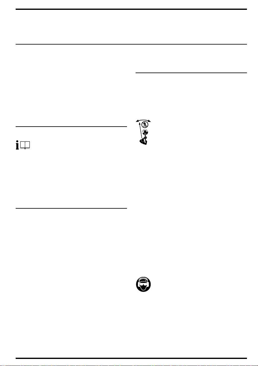
Safety instructions
T raining
• Never allow children or persons who are
unfamiliar with this type of trimmer to use
it, nor anyone who has not read this user
360˚
6m/20ft
manual.
• Do not allow children, animals or other
persons near your trimmer when in use always keep them at least 6m (20ft) away
from the cutting area.
• Remember that the operator is
responsible for accidents or hazards
occurring to other people or their property.
• Your trimmer is designed for use on AC
(mains) electrical supplies only - do not
attempt to use it on any other supply.
• Plug your trimmer into a power point -
never a lighting socket.
• Never carry your trimmer by the cable or
jerk the cable to seperate the
connectors. Keep the cable away from
heat sources, oils or sharp edges. Check
the condition of your cable before use
and do not use if damaged.
Preparation
• To protect your feet, always wear stout
shoes or boots - freshly cut grass is
damp and slippery.
• Rubber or man-made footwear will
enhance your safety.
• Do not operate your trimmer barefoot or
in open sandals.
• Use protective equipment. Wear safety
spectacles or goggles whilst operating
your trimmer. Use ear pr otection if the
sound level seems uncomfortable when
using your trimmer.
• Use a face mask if dusty.
• Wear long trousers to protect your legs -
any debris left on the lawn or cutting path
may be picked up and ejected by the line.
• The power supply cable should be
regularly inspected for signs of damage or
ageing, and only used if in good condition.
2
Page 3

• Always keep the power supply cable
away from the line - be aware of its
position at all times.
• Always be sure your trimmer is in a safe
operating condition.
• Always switch off and remove the plug if
the supply cable has become damaged
!
or entangled.
• Before using your trimmer, disconnect it
from the electrical supply and visually
check that the spool assembly is secure.
Never fit metal cutting line or wire to your
trimmer.
• Always check that your lawn or cutting
path is clear of all sticks, stones, wire
and other debris. Contact with such
debris may be dangerous or may
damage your trimmer.
• Take care against injury from the guard
trimming blade.
Operation
• Your trimmer will continue to run for a
short time after releasing the switch lever.
Always allow your trimmer to stop on
its own.
• Release the switch lever to turn your
trimmer off and remove the plug from
the mains:
• Whenever you leave your trimmer
unattended.
• Before checking, cleaning, adjusting
or working on your trimmer.
• Before clearing a blockage.
• If your trimmer starts to vibrate
abnormally (check immediately).
• After striking a foreign object, inspect
your trimmer for damage and make
repairs as necessary.
• Do not put hands or feet near or under
rotating parts.
• Start your trimmer carefully according to
the instructions and with your feet well
away from the cutting line.
• Do not use your trimmer in the rain and
do not allow it to get wet. Avoid using
your trimmer in wet grass, if possible.
• Use your trimmer only in daylight or good
artificial light.
• Do not cross gravel paths or roads whilst
the line is rotating.
• Always be sure of your footing,
particularly on slopes.
• Always cut across the face of slopes,
never up and down.
ENGLISH
• Exercise extreme caution when changing
direction on slopes.
• Do not cut excessively steep slopes and
always wear non-slip footwear.
• Walk, never run. Do not force your trimmer .
• Always use your trimmer in the manner
outlined in this manual. Y our trimmer is
designed to be used in an upright
position and if it is used in any other way
it may result in injury. Never run your
trimmer whilst it is lying on its side or
upside down.
• Never operate your trimmer with
defective guards or shields and always
operate with the guard in position.
Maintenance and storage
• Store your trimmer in a dry place when
not in use, out of the reach of children.
• Do not use solvents or cleaning fluids to
clean your trimmer - use a blunt scraper
to remove grass and dirt.
• Always disconnect from the electrical
supply before cleaning.
• Do not operate your trimmer if any parts
are defective; discard all defective parts
and fit new parts before use.
• Keep all nuts, bolts and screws tight to
be sure your trimmer is in a safe working
condition.
• Use only Black & Decker recommended
replacement parts and accessories.
Black & Decker’s policy is one of continuous
improvement to our products and, as such, we
reserve the right to change product specifications
without prior notice.
Double insulation
Your trimmer is double insulated.
This means that all external metal parts are
electrically isolated from the power supply.
This is achieved by placing an extra
insulation barrier between the electrical and
mechanical parts. Double insulation means
greater electrical safety and obviates the
necessity of having your trimmer earthed.
3
Page 4
Electrical safety (UK only)
Your trimmer should always be switched off
at the mains before disconnecting any plug
!
and socket connector or extension cables.
Fuse replacement
If your trimmer is supplied with cable fitted
with a non-re-wireable plug:
• The plug is fitted with a 5 amp fuse
which is the recommended fuse for
your trimmer.
• Only use replacement fuses which are
approved to BS1362.
• When changing the fuse in your plug,
always ensure the fuse cover is refitted.
If the fuse cover is missing or damaged
do not use the plug.
Note: Fuses do not give personal protection
against electric shock.
Plug replacement
• Disconnect the plug from the supply.
• Cut off the plug and dispose of
immediately. Insertion of a detatched
plug into a 13 amp socket outlet may
result in electric shock.
• Only fit BS1363A approved plugs fitted
with the correctly rated fuse.
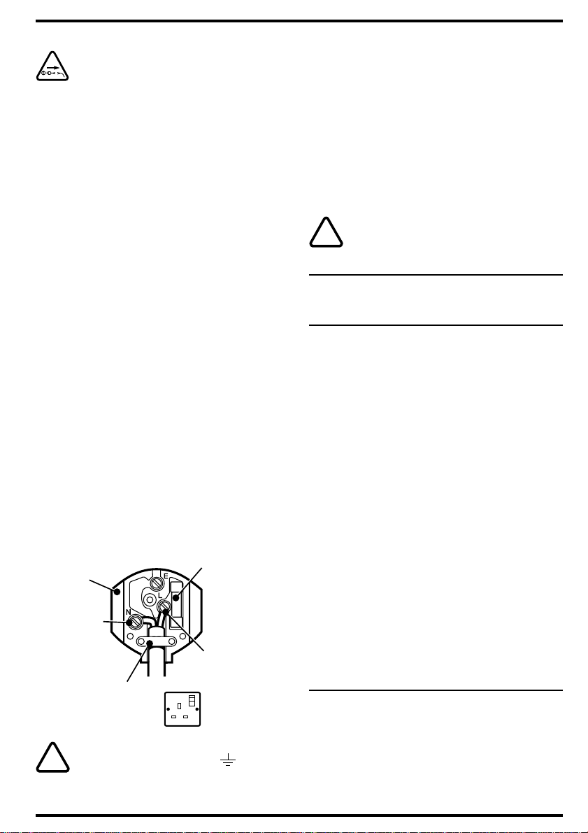
• The cable wire colours, or a letter , will be
marked at the connection points of most
good quality plugs. Attach the wires to
their respective points in the plug (see
below). Brown is for “Live” (L) and blue is
for “Neutral” (N).
• Before replacing the top cover of the
mains plug ensure that the cable restraint
is holding the outer sheath on the cable
firmly and that the two leads are correctly
fixed at the terminal screws.
Fit a
BS1363A
approved
plug
Connect blue
to N (neutral)
Make sure that the
outer sheath of the
cable is held firmly
by the clamp
Warning! Never connect live or neutral wires
to the earth pin marked “E” or .
!
Note: Do not wire an extension cable directly
into your trimmer yourself. Instead, take your
Fit the
recommended
fuse
Connect brown
to L (live)
240 volts AC only.
Never use a light
socket
trimmer to your nearest Black & Decker
service agent.
Increased safety can be obtained by having
a qualified electrician install a high sensitivity
(30mA) circuit breaker in the house wiring.
If you do not have such a circuit breaker
installed, or you do not wish to have one
installed, then we strongly recommend that
the electrical power to your trimmer be
supplied through a high sensitivity residual
current device (RCD). The RCD is designed
to provide a high degree of personal
protection against harmful electric current
should fault conditions occur.
Warning! The use of an RCD or other circuit
breaker unit does not release the operator of
!
your trimmer from the safety instructions and
safe working practices given in this manual.
The following five sections only refer
to products supplied without a cable.
Cable connection system (UK only)
Black & Decker continually make every effort to
achieve the highest standards in performance,
quality and reliability and recommend the use of a
new outdoor cable connection system.
The new system gives additional protection against
the possibility of water or moisture entering into the
cable connector during normal use.
Note: The new connection system does not release
the operator of the machine from the safety
precautions and safe working practices given in this
user manual. Particular attention is drawn to the
coupler system as being “weather resistant” and not
suitable for immersion, submersion or being
subjected to water jets. Care should be taken to
prevent the cable from lying or trailing through pools
of water or from splashing with hose pipes.
The new cable system is available in various lengths
through most major DIY retail outlets:
A6615 20m heavy duty cable, new socket
A6616 20m heavy duty cable, new socket
A6617 30m heavy duty cable, new socket
13 amp plug
13 amp plug and cable tidy system
13 amp plug and cable tidy system
Existing cable systems (UK only)
If you already own an outdoor cable system, we
recommend that you replace the existing ‘female’
cable connector with the new ‘female’ connector
(see opposite) which is supplied loose in the carton.
(Please read the section entitled “Fitting the ‘female’
connector”.)
4
Page 5
old ‘female’ connector new ‘female’ connector
Should you wish to convert more than one cable
system, the new female connector is available as an
accessory from most major DIY retail outlets and from
Black & Decker service agents (cat. no. A6624S).
Existing powered garden tools
(UK only)
To connect existing Black & Decker garden power
tools to the new system you will require an adaptor
(see below). This is available as an accessory from
most major DIY retail outlets (cat. no. A6623S).
Warning! This adaptor is only suitable for
products rated up to 500W.
!
It is not recommended for use with the
following:
Hover mowers
Rotary mowers with grass collection
Chainsaws
Shredders
Blowervacs.
Please contact your local service agent
should you require further advice.
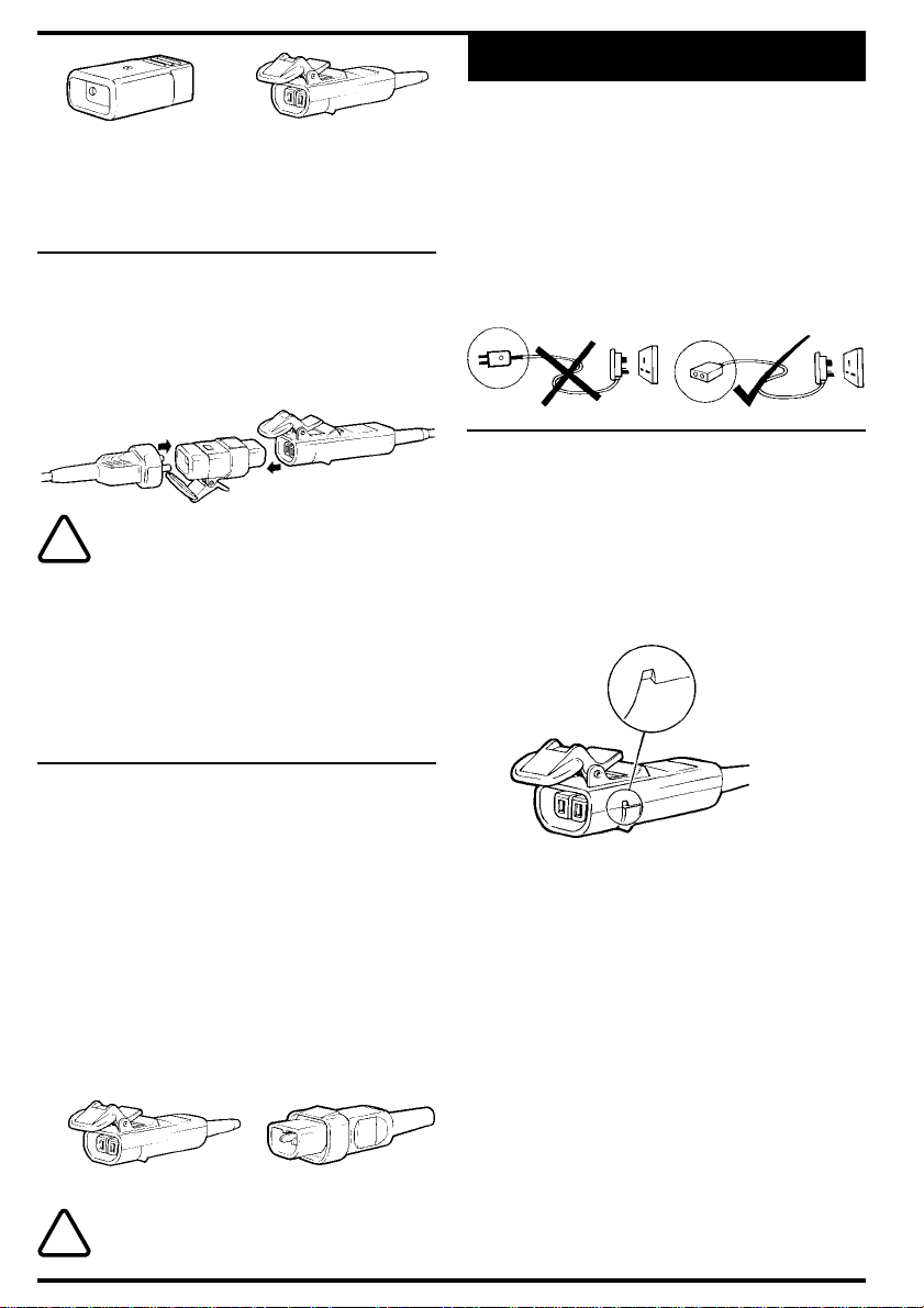
ENGLISH
plug with the recommended fuse. Never
wire a ‘male’ connector to your extension
cable and never wire an extension cable
with a plug of any kind at each end of the
cable. This is extremely dangerous and
results in the pins being live which may
cause a fatal electric shock.
Fitting the ‘female’ connector
(UK only)
To remove the cover, unscrew the fixing screw until it
is free of the nut which is located in the hexagonal
recess on the underside of the connector. Take car e
not to lose the nut if it falls out. There is no need to
completely remove the fixing screw as it is intended
to remain captive in the cover. The cover can now be
removed by applying pressure as shown below.
apply pressure here
Fitting your own extension cable
(UK only)
• When fitting your own extension cable fit a
13 amp plug (see “Fitting the mains plug”) to one
end of the cable and a ‘female’ connector
(supplied loose in the carton) to the other end
(see opposite). For wiring instructions see the
following sections.
• A ‘male’ connector is already attached to the
electrical supply cable on your mower and is
designed to be non-rewireable (see opposite).
This should not be removed. Should the
cable and plug become damaged or need
replacing, please return your mower to your local
Black & Decker service agent.
‘female’ connector ‘male’ connector
Warning! Never wire an extension cable with
anything other than the ‘female’ connector
!
supplied and a 13 amp BS1363A approved
The extension cable contains two wires which are
colour coded for easy recognition; brown is for ‘Live’
(L) and blue is for ‘Neutral’ (N). The female connector
is marked ‘L’ for live and ‘N’ for neutral. These
markings are located inside the body near the
terminal screws (see opposite, figure a). With the
connector cover removed, lift out the cable protector
and proceed as follows:
• Pass the cable through from the narrow end of
the cable protector (see opposite, figure a).
• Prepare the cable ends to the specified strip
lengths (see opposite, figure b).
• Remove cable clamp (see opposite, figure a).
Take care of loose parts.
• To connect the extension cable to the connector
terminals, unscrew the terminal screws until the
clamp washers have lifted just enough to enter
the conductor between the raised washer and
the terminal (see below). Connect the brown lead
to ‘L’ and the blue lead to ‘N’.
5
Page 6

Note: There is no need to remove the terminal
screws. Connections are not to be made under
the screw heads.
terminal screw
clamp terminal
washer conductor
position
to left of screw
• Locate the cable and cable protector into the
body correctly (see below, figure a). Then fit the
cable clamp over the outer sheath of the cable
and screw down until the screws are fully home.
Failure to do this may result in the cover not
fitting correctly to the connector body.
• Before replacing the cover of the ‘female’
connector make sure that the cable clamp is
holding the outer sheath of the cable firmly with
screws fully home and that the two leads are
correctly fixed at the terminal screws and ar e not
taut (see below, figure a).
• Place the cover onto the body assembly
ensuring that it seats flat, then retighten the fixing
screw into the nut until the cover is securely held
(see below, figure c).
• Finally check that the cable protector is secure
and that there are no gaps between the cover
and the connector body.
terminal screws
clamping washers
connector body fixing screw
6mm
• Place the guard over the spool housing
B
on your trimmer taking care that the line
does not become stuck between the
two parts.
• Align the square marking on the guard
C
with the square marking on your trimmer
body and push the guard upwards until it
almost contacts the underside of the
body. Now turn the guard in the direction
indicated by the arrow.
• The guard is secure when the ridges on
D
the guard have fitted into the slots in the
body, and the spring finger has located.
• Once the guard is in position, secure the
guard screw which goes through the
guard screw hole and into screw boss in
the body.
• To avoid damage in transit, the spool has
been packed in a polythene bag.
Assembling the spool (Fig. E)
• Thread the line through the hole in the
E
inner cover and then unclip the line from
the groove in the top face of the spool.
• Place the inner cover on the spool.
• Ensure that sufficient line is threaded
through the hole in the inner cover before
fitting the spool to the spool carrier.
• Grip the spool with one hand and the
spool carrier with the other. Fit the spool
by pushing down in the direction of arrow
(a) and twisting clockwise in the direction
of arrow (b) until you feel it click into
position.
cable
clamp cover
cable
protector
Preparing your trimmer for use
(Fig. B - D)
• Take your trimmer, guard and parts pack
out of the box.
• Remove the guard screw from the parts
pack.
6
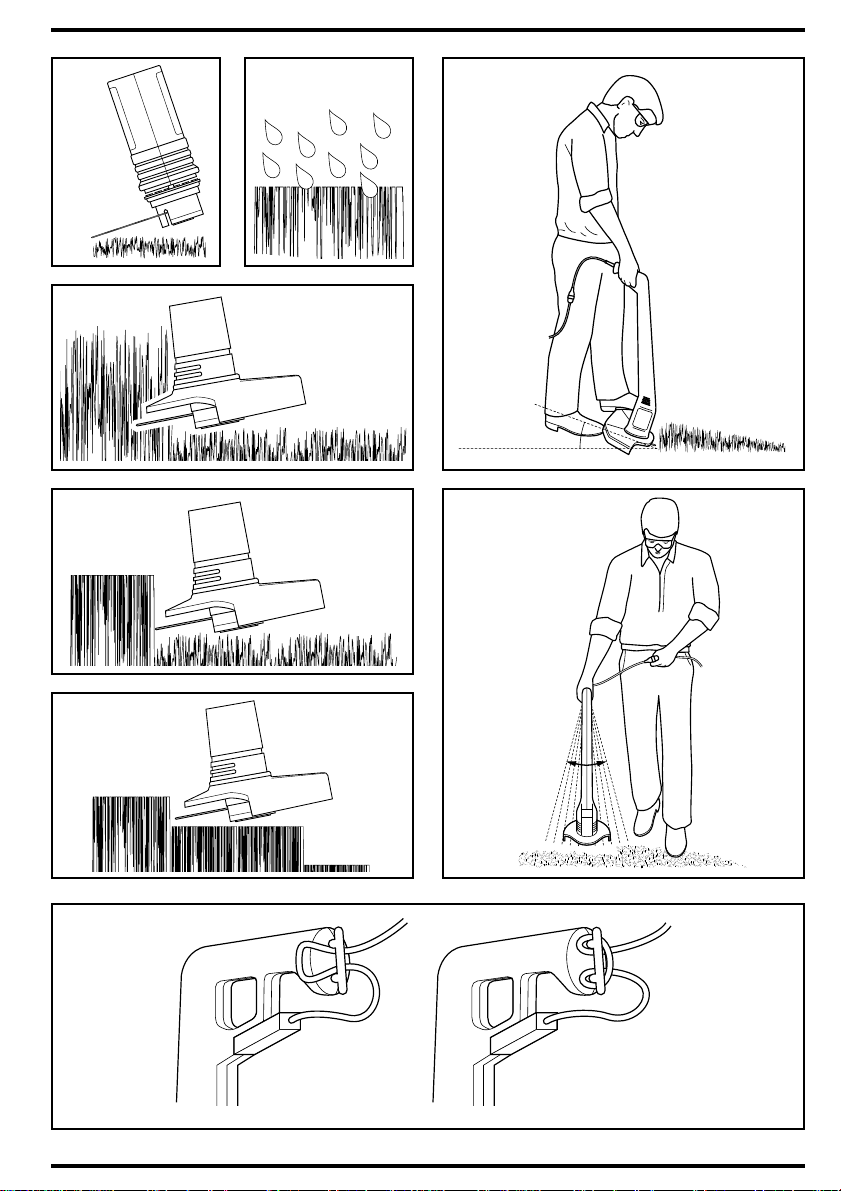
How to use your trimmer (Figs. 1 - 8)
To switch on your trimmer press the switch
lever. To switch off your trimmer, release the
switch lever.
In order to get the most from your trimmer
please learn the following techniques.
Do not be impatient, you will obtain the best
results by experience and by following these
simple rules.
Do not use your trimmer without its guard.
1
Do not cut wet grass, best results are
2
achieved when the grass is dry.
Cut at an angle and with the tip of the nylon
3
line. Your trimmer is balanced to operate at
this angle.
Swing your trimmer gently from side to side.
4
Page 7

Do not overload your trimmer. It operates
5
best at high speeds.
On long grass, start at the top.
6
Take small cuts.
7
If your trimmer features a cord restraint,
8
loop a length of cord through the restraint to
prevent the plug and socket coming apart
accidentally if the cord is pulled.
Feeding out more nylon line (Fig. F)
Note: There must be a minimum of 5cm
(2 inches) of nylon line protruding from the
spool cover before your manual-feed trimmer
is operated:
• Hold the spool housing firmly with one
hand, and the nylon line with the other,
then pull the nylon line out of the slot.
• Pull the nylon line out of the spool
F
Fitting a new spool of nylon line
(Fig. G)
G
housing in the direction of arrow (a).
• Continue to pull the nylon line out of the
spool housing, in the direction of arrow
(b), until there is sufficient line to reach
the edge of the guard, then pull the nylon
line down into the next slot in the spool
housing as indicated by arrow (c).
Note: When your trimmer is operated for the
first time, any excess line will be cut off by
the blade housed in the guard. This is also
the case for any subsequent line adjustment.
Because line cut off by the trimming blade in
the guard may be ejected, it is important that
the amount of excess line is kept to a
minimum. Where an excessive amount of
line is pulled out, the line should be cut back
to the outside of the guard befor e switching
on your trimmer.
• Your manual feed trimmer is now ready
for use.
• Remove the spool and inner cover by
pushing down and turning anticlockwise
in the direction of arrow.
Fit a new , full spool as described in
‘Assembling the spool cover’. Alternatively, fit
new nylon line to the empty spool as follows:
• Locate one end of the nylon line in one of
the grooves in the spool and wind the
line on to the spool in the direction of the
arrow (anti-clockwise) until it is full.
ENGLISH
• Fit the inner cover onto the spool and fit
the spool onto your trimmer as described
in ‘Assembling the spool cover’.
Replacement line
A new spool containing 5.5 metres of nylon line may
be purchased from your Black & Decker agent.
Alternatively, replacement lines containing 25 to 50
metres of line are available.
For maximum reliability never put on a heavier or
lighter line (eg. fishing line) which will cause motor
failure or reduce cutting performance.
Care and maintenance
• For the best performance, please keep the nylon
line, spool and air slots in your trimmer body
clean. Use a dry brush or cloth to remove grass,
sap or other dirt.
• Plastic parts may be cleaned by using a mild
soap and a cloth dampened with hot water.
Do not use any other type of detergent, cleaner
or solvent which might contain chemicals that
could seriously damage the plastic. Do not spray
your trimmer with water.
• Self lubricating bearings are used in this tool and
so lubrication is not required.
Fault finding
Before checking your trimmer for any faults,
disconnect it from the mains.
• If your trimmer vibrates, remove the spool and
replace it in a new position. If this does not cure
the problem try removing the spool and
rewinding the nylon line more tightly on the spool
before replacing it.
• If your trimmer will not start check that all power
cables are properly connected. If this does not
work, check your power point then check the
fuse and wiring on the cable extension plug and
female connector.
What to do if your string trimmer
needs repair
For after sales service please refer to the section
‘Lawnmowers & Garden’ within your local
Yellow Pages.
7
Page 8

ENGLISH
Unwanted products and the
environment
Should you find one day that your trimmer
needs replacement, or is of no further
use to you, think of the protection of the
environment. Black & Decker service agents
will accept your old trimmer and will dispose
of it in an environmentally safe way.
genuine Black & Decker accessories and parts may
damage or reduce the performance of your
Black & Decker product and may also endanger the
user. The terms and conditions of the warranty may
also be effected.
It is our aim that all Black & Decker customers should
be totally satisfied with their Black & Decker product
and after sales service, if help or advice is needed
please contact a local Black & Decker authorised
repair agent who will be happy to help. Full details of
our after sales service can be obtained from any of
our Black & Decker authorised repair agents.
This user manual contains a full directory and parts
drawing.
Black & Decker lawn and garden
guarantee
lf your Black & Decker trimmer becomes defective,
within the guarantee period, due to faulty materials
and workmanship, we guarantee to either replace all
defective parts, or at our discretion, replace your
trimmer free of charge, provided that:
• Your trimmer is returned to one of our authorised
repair agents with evidence of purchase.
• Your trimmer has been used within the
parameters of its consumer classification.
• Your trimmer has not been used for hire purposes.
• Repairs have not been attempted by anyone
other than our authorised repair agents.
• The failure represents normal wear and tear.
This guarantee is offered as an extra benefit and is
additional to your statutory rights.
Our guarantee policy
Failure due to the following are not covered:
• Replacing worn or damaged blades, nylon line
and chains, or cables damaged during storage
or use. These are regarded as replacement items
which wear during normal usage.
• Failure as a result of sudden impact or obvious
abuse.
• Failure due to usage not in accordance with
instructions and recommendations contained in
this manual.
The use of other than genuine Black & Decker
accessories and parts may damage or reduce the
performance of your Black & Decker trimmer and
may render the guarantee void.
Other Black & Decker products
(UK only)
Black & Decker has a full range of outdoor power
tools that make life easy in the garden. If you would
like further information on other products, please
contact the Black & Decker Service Information
Centre at the address towards the back of this
manual, or contact your Black & Decker stockist.
Lawnmowers String trimmers
Chainsaws Lawnrakers
Compost shredders Leafbusters
Blade trimmers Cordless brooms
Cordless trimsaws Cordless shrubbers
Cordless shears Hedgetrimmers
EC Declaration of Conformity
We declare that units:
GL200, GL300, GL320, GL325, GL330, GL335,
GL555, GL565, ST20, ST22, ST23, ST25, ST32
conform to: 89/392/EEC, 89/336/EEC,
73/23/EEC, EN55014, EN55104, EN60335
A weighted sound pressure 95dB (A)
A weighted sound power 108dB (A)
Hand/arm weighted vibration <2.5m/s
Brian Cooke
Director of Engineering
Spennymoor, County Durham DL16 6JG
United Kingdom
2
Black & Decker after sales service
(UK, Australia and New Zealand only)
Black & Decker offers a nationwide network of
authorised service agents. The use of other than
8
Page 9

TYP.
®
GL200/GL300
8
7
H1E
15
22
13
10
21
24
3
4
1
5
6
2
19
9
12
13
11
13
13
11
17
E11851 / 749498
16
20
23
14
01 / 96
25
9
Page 10

Australia Black & Decker (A’asia) Pty Ltd Tel: 03 9213 8200
New Zealand Black & Decker Tel: 09 579 7600
South Africa Black & Decker South Africa (Pty) Ltd Tel: 011 314 4431
United Kingdom Black & Decker Tel: 01753 574277
286-288 Maroondah Highway, North Croydon, Victoria 3136 Fax: 03 9726 7150
483 Great South Road, Penrose, Auckland Fax: 09 579 8200
Suite no 107, PostNet X65, Halfway House 1685 Fax: 011 314 4435
210 Bath Road, Slough Tlx: 848317 BAND MH
Berkshire SL1 3YD Fax: 01753 551155
Part no. 371356-17 10/97.1
10
®
Page 11

Yes No
Date of your purchase:
Address of the dealer where your string trimmer was purchased:
Was your string trimmer a gift?
Was your string trimmer your first purchase?
Was your string trimmer bought as a replacement?
What was the price of your string trimmer?
Name:
House number or name and street:
Town:
County or state:
Postcode:
Address of the dealer where your string trimmer was purchased:
GL___/___
Country:
Product catalogue number:
Data protection act: Tick this box if you prefer not to receive
information from Black & Decker or other companies.
11
Page 12

If you live in Australia or New Zealand, please register your purchase by using the
Please complete this section immediately after the purchase of your string trimmer
South Africa: Black & Decker South Africa (Pty) Ltd, Suite no 107, PostNet X65, Halfway House 1685
and post it to the Black & Decker address in your country (above).
United Kingdom & Ireland: PO Box 821, Slough, Berkshire, SL1 3AR
alternative guarantee card supplied in the carton.
GUARANTEE CARD
Part no. 371356-17 10/97.1
Page 13

®
GL200
GL300
Page 14
1
✗
5
2
✗
3
✗
o
20
6
7
8
4
14
Page 15

A
2
3
B
1
6
8
D
1
4
5
7
6
8
14
C
5
910
11
12
8
15
1
6
6
13
15
Page 16

E
a
b
F
b
7
c
14
17
5
8
G
18
16
ac
16
5
8
6
14
18
5
 Loading...