

Page 1

SHORT HAUL,
ASYNCHRONOUS / SYNCHRONOUS
4 WIRE MODEM FOR PRIVATE LINES
1.2 to 128 Kbps
SHM® 128
USER'S GUIDE
ORIGINAL ISSUE: FEBRUARY 01, 2000
UPDATE: NOVEMBER 25, 2004
P/N: 511004311
Page 2

SHM 128 - 511004311 - Update: 11/25/2004 2/31
RECOMMANDATIONS
The line circuit as well as the interface circuits at the back of the
product are SELV circuit. Compliance with EN60950 is only
maintained if they are connected to line or port on other
equipments which only contain SELV circuit as specified in
EN60950.
DISCONNECTING THE PRODUCT
Before opening the housing servicing, product must be
disconnected from the main power supply. To enable this, power
must be installed near the product and must be easily accessible.
AETA.COM reserves the right to modify the products described in
this guide at any time and without prior notice.
DECLARATION OF CONFORMITY
The manufacturer declares that the AEMOD 128 short haul
modem conforms to the following standards :
EN 55022 Ed. 94 Electromagnetic radiations
EN 55024 Ed. 98 Electromagnetic immunity
EN 60950 Ed. 98 Safety requirements
CE MARK
The CE mark on this product applies to the EMC directive
89/336/EEC and to the Low Voltage Directive 73/23/EEC.
Page 3

SHM 128 - 511004311 - Update: 11/25/2004 3/31
CONTENTS
I PRESENTATION
II INSTALLATION
III INTERFACES
IV DISPLAYS AND TESTS FEATURES
V OPERATIONS
VI RANGE
VII MICRO SWITCH POSITIONS SUMMARY
Page 4

SHM 128 - 511004311 - Update: 11/25/2004 4/31
I – PRESENTATION
Front panel
Rear panel V28,V35 and 230V~ unpluggable terminal block
Rx Tx
Jonction
Al.
230V
50Hz
15mA
Rear panel V11 and 230V~ unpluggable terminal block
Tx Rx
Jonction
Al.
230V
50Hz
15mA
Page 5
SHM 128 - 511004311 - Update: 11/25/2004 5/31
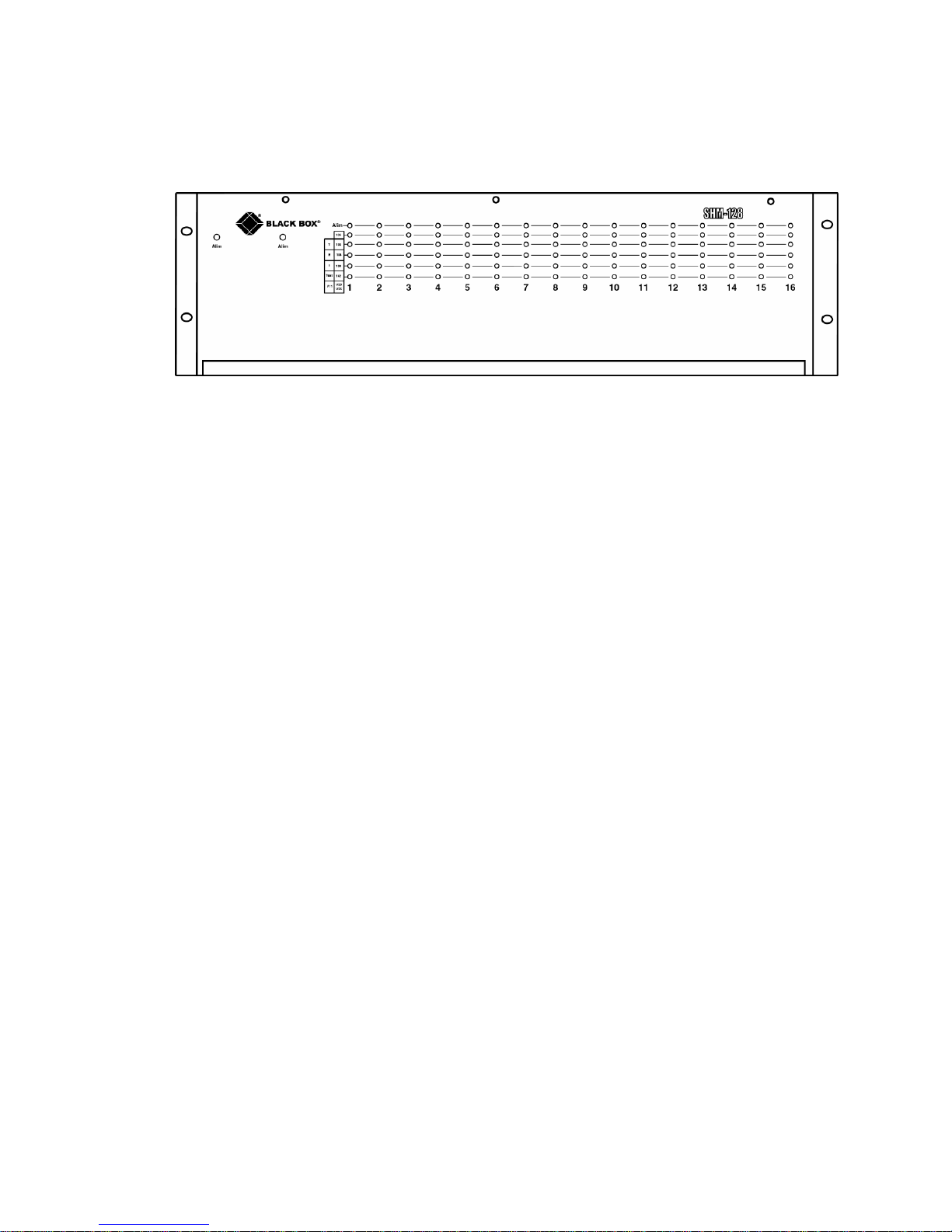
Chassis front panel
The rack-mount chassis can contain:
up to 16 modem cards
up to 2 power cards
Page 6

SHM 128 - 511004311 - Update: 11/25/2004 6/31
II - INSTALLATION
1. Power supply
Connect all secondary supply wires before connecting the
mains power plug.
Standalone versions:
Standalone 230V version: plug the power cord to the mains power
socket.
The “Alim” LED must light on. If it does not, check the F1 fuse on
the board (250V delayed 400mA).
Standalone 48V version : connect the 48V supply to the 48V
screw terminals (polarity doesn't matter).
The “Alim” LED must light on. If it does not, check the F1 fuse on
the board (250V delayed 63mA).
Page 7

SHM 128 - 511004311 - Update: 11/25/2004 7/31
Rack-mount versions:
Rack-mount 230V version:
Plug the 230V power card in slot A or B of the chassis.
For backup, plug a second 230V power card in the other slot.
Plug the mains cord in the outlet at the back of the chassis and in
the mains power socket.
The “Alim” LED of the power card must light on. If it does not,
check the F1 fuse on the board (250V delayed 1A).
The “Alim” LED of a modem card must light on. If it does not,
check the F1 fuse on the board (250V delayed 400mA).
Rack-mount 48V version:
Plug the 48V power card in slot A or B of the chassis.
For backup, plug a second 48V power card in the other slot.
Connect the +48V wire of the power supply to the screw connector
block tagged 0B and located at the back of the chassis.
Connect the 0V wire of the power supply to the screw connector
block tagged –48V and located at the back of the chassis.
The “Alim” LED of the power card must light on. If it does not,
check the F1 fuse on the board (250V delayed 2A).
The “Alim” LED of a modem card must light on. If it does not,
check the F1 fuse on the board (250V delayed 400mA).
Page 8

SHM 128 - 511004311 - Update: 11/25/2004 8/31
2. Line wiring:
Warning: The efficiency of AEMOD 128 is guaranteed only
with a two twisted pairs cable.
The two Tx line wires are connected to the two Rx line wires of the
other end.
Screw connector block standalone or chassis version:
Tx
The transmit line is connected to
the terminals :
The receive line is connect to the
terminals :
Rx
RJ45 standalone unit:
RJ45 pinouts:
RJ45
receptacle
pin number
Description
1 Not used
2 Not used
3 Rx
4 Tx
5 Tx
6 Rx
7 Not used
8 Not used
Page 9

SHM 128 - 511004311 - Update: 11/25/2004 9/31
REMARK:
The way of plugging the two Tx wires has no importance. The
same for the way of plugging the two Rx wires.
NOTE: As an option, a 3 meter long cord fitted with a RJ45 plug
at one end and a spade lug at the other end can be delivered.
3. Terminal connection:
V28 version: connect directly the terminal to AEMOD 128 using a
DB25 female connector .
V35 version: connect the DB25M / M34F adaptor cord (delivered
with the device) to the 'Jonction' connector of AEMOD 128. Then
use a M34 cord to connect the terminal to AEMOD 128.
V11 version: connect the DB25M / DB15F adaptor cord (delivered
with the device) to the 'Jonction' connector of AEMOD 128. Then
use a DB15 M34 cord to connect the terminal to AEMOD 128.
4. Alarm contact:
A 2 pins contact ('Al.') is available at the rear side of AEMOD
128.
The device provide a loop which is open when no line signal is
detected by the modem.
Page 10

SHM 128 - 511004311 - Update: 11/25/2004 10/31
III - INTERFACES
1. V28 interface
ITU-T : V24 + V28 (RS232)
ISO : 2110
Circuit Pin Meaning Name Signal
source
ITU-T
EIA
102 AB 7 Signal ground GND
103 BA 2 Transmit data TD
→
104 BB 3 Receive data RD
←
105 CA 4 Request to send RTS
→
106 CB 5 Clear to send CTS
←
107 CC 6 Data set ready DSR
←
108 CD 20 Data terminal ready DTR
→
109 CF 8 Data carrier detect DCD
←
113 DA 24 External transmit clock ExtClk
→
114 DB 15 Modem transmit clock TC
←
115 DD 17 Modem receive clock RC
←
140 RL 21 Remote loop back RLB2
→
141 LL 18 Local loop back LLB3
→
142 TM 25 Test indicator TI
←
→ Terminal signal source
← Modem signal source
Page 11

SHM 128 - 511004311 - Update: 11/25/2004 11/31
2. V11 interface
ITU-T : V11 (RS422)
ISO : 4903
Circuit
Pin Meaning Name Signal
source
G 8 Signal ground
T 2
9
Transmit data wire (a)
Transmit data wire (b)
Ta
Tb
→
→
R 4
11
Receive data wire (a)
Receive data wire (b)
Ra
Rb
←
←
C 3
10
Control wire (a)
Control wire (b)
Ca
Cb
→
→
I 5
12
Indicator wire (a)
Indicator wire (b)
Ia
Ib
←
←
S 6
13
Transmit and receive
clock signal wire (a)
Transmit and re
ceive
clock signal wire (b)
Sa
Sb
←
←
X 7
14
Ext. Clock wire (a)
Ext. Clock wire (b)
Xa
Xb
→
→
→ Terminal signal source
← Modem signal source
Page 12

SHM 128 - 511004311 - Update: 11/25/2004 12/31
V11 Adaptator
DB25M
DB15F
1
Protective ground
1
2
Tx(a) T(a)
2
3
Rx(a) R(a)
4
4
RTS(a) C(a)
3
5 CTS(a)
6
DSR(a)
7
GND GND
8
8
DCD(a) I(a)
5
9
Hrec(b) S(b)
13
10
DCD(b) I(b)
12
11
Hext(b) X(b)
14
12
13
14
Tx(b) T(b)
9
15 Hem(a)
16
Rx(b) R(b)
11
17
Hrec(a) S(a)
6
18
19
RTS(b) C(b)
10
20
21
22
23
24
Hext(a) X(a)
7
25
Page 13

SHM 128 - 511004311 - Update: 11/25/2004 13/31
3. V35 interface
ITU-T : V35
ISO : 2593
Circuit
Pin Meaning Name Signal
source
101 Protective ground
102 B Signal ground GND
105 C Request to send RTS
→
106 D Clear to send CTS
←
107 E Data set ready DSR
←
109 F Data carrier detect DCD
←
108 H Data terminal ready DTR
→
104 R
T
Receive data wire (a)
Receive data wire (b)
RD
←
←
115 V
X
Receive clock wire (a)
Receive clock wire (b)
RC
←
←
114 Y
AA
Transmit clock wire (a)
Transmit clock wire (b)
TC
←
←
103 P
S
Transmit data wire (a)
Transmit data wire (b)
TD
→
→
113 U
W
Ext. transmit clock wire
(a)
Ext. transmit clock wire
(b)
ExtClk
→
→
140 N Remote loop back RLB
→
141 L Local loop back LLB
→
142 NN Test indicator TI
←
→ Terminal signal source
← Modem signal source
Page 14

SHM 128 - 511004311 - Update: 11/25/2004 14/31
V35 Adaptator
DB25M
M34F
1
Cable screen
A
2
Tx(a)
P
3
Rx(a)
R
4
RTS
C
5
CTS
D
6
DSR
E
7
GND
B
8
DCD
F
9
Hrec(b)
X
10
11
Hext(b)
W
12
Hem(b)
AA
13
14
Tx(b)
S
15
Hem(a)
Y
16
Rx(b)
T
17
Hrec(a)
V
18
Bcl3
L
19
20
DTR
H
21
Tbcl2
N
22
23
24
Hext(a)
U
25
Test
NN
Page 15

SHM 128 - 511004311 - Update: 11/25/2004 15/31
4. RS530 interface
ISO : 2110
Pin Meaning Name Signal
source
7 Signal ground
2
14
Transmit data
Transmit data
TD a
TD b
→
→
3
16
Receive data
Receive data
RD a
RD b
←
←
4
19
Request to send
Request to send
RTS a
RTS b
→
→
5
13
Clear to send
Clear to send
CTS a
CTS b
←
←
6
22
Data set ready
Data set ready
DSR a
DSR b
←
←
8
10
Signal detector
Signal detector
SD a
SD b
←
←
20
23
Data terminal ready
Data terminal ready
DTR a
DTR b
→
→
15
12
Transmit clock
Transmit clock
TC a
TC b
←
←
17 9 Receive clock
Receive clock
RC a
RC b
←
←
24
11
External clock
External clock
ExtClk a
ExtClk b
→
→
18 Local loop back LLB
→
21 Remote loop back RLB
→
25 Test mode T
←
→ Terminal signal source
← Modem signal source
Page 16

SHM 128 - 511004311 - Update: 11/25/2004 16/31
IV – DISPLAYS AND TESTS FEATURES
1. leds
Led "Alim" lights up when the modem is powered on.
Led "106" lights up when CTS signal is on.
Led "103/T" lights up when transmitted data is "0".
Led "104/R" lights up when received data is "0".
Led "109/I" lights up when line signal detector is on.
Led "142/Test" lights up when a local or remote loop back
is in progress.
2. Loop facility
Complying with ITU-T V54, two loops are possible:
A – Analog loop (Loop 3)
Controlled by the switch Bcl3 (or the micro switch S9 for the
chassis version) or by the CT141 circuit.
terminal
Local
Line
Transmitter
Receiver
Local loop type 3
Local modem is disconnected from the line. Transmit line is
looped to receive line on local modem. Data transmitted by the
terminal are sent back by local modem. This loop back only allows
to test the local modem.
Page 17

SHM 128 - 511004311 - Update: 11/25/2004 17/31
B – Remote digital loop (RDL2)
Controlled by the switch Tbcl2 (or the micro switch S8 for the
chassis) or by the CT140 circuit.
terminal
Local
Line
Remote
loop
back
Rec.
Trans.
Rec.
Trans.
Remote digital loop type 2
The remote modem is looped. Data transmitted by local terminal,
via the local modem, are send to and returned from the remote
modem. This test can verify the integrity of the local modem, the
communication link and the remote modem.
Strap Z on position 2-1 inhibits loop back. On position 2-3 strap Z
allows CT140 controlled loop back.
Strap Z has no influence on S8 command.
Page 18

SHM 128 - 511004311 - Update: 11/25/2004 18/31
This strap in only accessible when the standalone box is opened.
This strap moving in only possible when opening the box.
To do it, just pinch one side of the front panel black frame, and
pull out the frame. (Pinching must be done on the stripped zones
of the frame side).
Strap ‘Z’ location:
Strap Z
3 1
Warning:
It is not possible to initiate a RDL2 loop from a modem actually
using the receive clock as the transmit clock.
C - Remote digital loop inhibition
S8 switch (or S10 switch for the chassis version) makes the
modem to ignore the remote digital loop request from the remote
modem.
A position: loop back allowed
B position: loop back inhibited
Page 19

SHM 128 - 511004311 - Update: 11/25/2004 19/31
V - OPERATION
1. Transmit control
Line transmit signal may be:
- controlled by RTS (S7 on position A)
- permanent (S7 on position B)
DTR interface signal may be used or not by the modem depending
on strap Y:
- Y 1-2 : DTR is ignored (Factory setting)
- Y 2-3 : DTR must be at space level
Strap ‘Y’ location :
Strap Y
3 1
Page 20

SHM 128 - 511004311 - Update: 11/25/2004 20/31
CTS/RTS delay is controlled by S6 micro switch and operating
mode.
S 6 Operating mode
Delay time
CTS/RTS
B Synchronous 4 800 bd to 38 400 bd Delay time 25ms
A Synchronous 4 800 bd to 38 400 bd Delay time 50ms
B Synchronous 64 000 bd to 128 000 bd
Delay time 4,5ms
A Synchronous 64 000 bd to 128 000 bd
Delay time 15ms
B Asynchronous Delay time 5ms
A Asynchronous Delay time 17ms
2. Synchronous mode - Transmit clock setup
A - Internal clock : CT114
Internal clock is supplied by the modem on CT114 (TC).
Micro switch S4 on position B and S5 on position A.
Data rate (micro switch S1, S2, S3).
B - External clock : CT113
Transmit clock is supplied by terminal on CT113 (ExtClk).
Micro switch S4 on position A and S5 on position A.
Data rate can range from 1,2 to 128 Kbps.
C - Receive clock : CT115
Receive clock is used by the modem as transmit clock and applied
on TC pin (CT114). Micro switch S4 on position A and S5 on
position B.
Page 21

SHM 128 - 511004311 - Update: 11/25/2004 21/31
D – RS422 specific feature
As there is only one clock (S) on the interface, there are only 2
ways to configure the transmit clock of the AEMOD 128 RS422:
a) one modem in internal clock and the other in receive clock
mode.
b) both modems in external clock.
Warning:
In case a), when one modem uses the receive clock as transmit
clock, the range is shortened.
3. Asynchronous mode
Asynchronous mode is obtained in placing micro switch S4 and S5
in position B.
Page 22

SHM 128 - 511004311 - Update: 11/25/2004 22/31
VI - RANGE
The distances indicated below correspond to a guaranteed minimum
range for twisted pairs of ∅ 4mm (AWG26).
For other diameters multiply roughly by:
1.3 for ∅ 0.5 mm (AWG24) ; 1.5 for ∅ 0.6 mm (AWG22);
2.0 for ∅ 0.8 mm (AWG20)
The range depends on the transmit clock used by modems:
1) TC = internal clock for both modems (RS232, V35).
TC = receive clock for both modems (RS232, V35, R422).
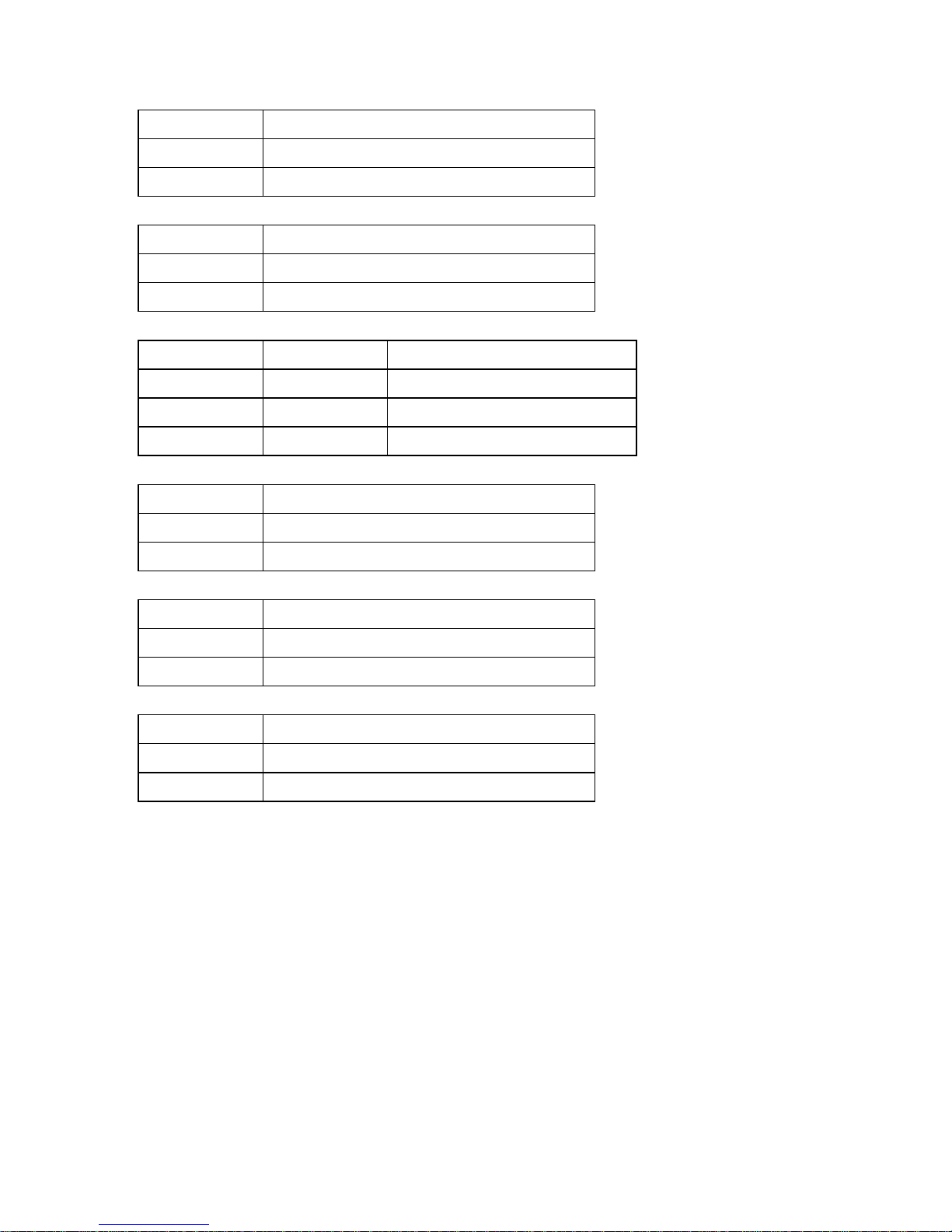
Rate (bps) Point to point
1.200
9.000 m
2.400
7.000 m
4.800
6.500 m
9.600
5.500 m
19.200
4.500 m
64.000
3.800 m
128.000
3.400 m
Page 23

SHM 128 - 511004311 - Update: 11/25/2004 23/31
2) RS232, V35, RS422
TC = internal clock on one side and,
TC = receive clock on the other side.
Rate (bps) Point to point
1.200
8.000 m
2.400
6.800 m
4.800
5.600 m
9.600
4.000 m
19.200
3.400 m
64.000
2.500 m
128.000
1.500 m
3) Asynchronous (V28).
Rate (bps) Point to point
1.200
8.700 m
2.400
7.000 m
4.800
6.600 m
9.600
5.000 m
19.200
3.800 m
Page 24

SHM 128 - 511004311 - Update: 11/25/2004 24/31
VII – MICRO SWITCH POSITIONS SUMMARY
* Factory settings
1. Standalone version
Synchronous mode:
S 1 S 2 S 3 Data rate (bps)
A A B 128.000
B A B 64.000
A B A 19.200*
B B A 9.600
A A A 4.800
B A A 2.400
A B B 1.200
S 4 S 5 Transmit clock
A A External clock
B A Internal clock*
A B Receive clock
Asynchronous mode:
S 1 S 2 S 3 Data rate (bps)
A
A
B
115.200
57.600
28.800
14.400
B A B 38.400
A B A 19.200
B B A 9.600
A A A 4.800
B A A 2.400
A B B 1.200
Page 25

SHM 128 - 511004311 - Update: 11/25/2004 25/31
S 4 S 5 Transmit clock
B B Asynchronous mode
S 6 Delay time CTS / RTS
B Low delay *
A Significant delay
S 7 Transmit control
A Controlled by RTS*
B Permanent
S 8 Remote loop inhibition
A Remote loop allowed*
B Remote loop inhibited
Bcl3 Analog loop 3
A No*
B Yes
Tbcl2 Remote digital loop 2
A No*
B Yes
Strap Y DTR management
1-2 Used by the terminal
2-3 Ignored*
Strap Z Remote loop inhibition
1-2 Yes
2-3 No*
Page 26

SHM 128 - 511004311 - Update: 11/25/2004 26/31
2. Rack-mount version
Synchronous mode:
S 1 S 2 S 3 Data rate (bd)
A A B 128.000
B A B 64.000
A B A 19.200*
B B A 9.600
A A A 4.800
B A A 2.400
A B B 1.200
S 4 S 5 Transmit clock
A A External clock
B A Internal clock*
A B Receive clock
Asynchronous mode:
S 1 S 2 S 3 Data rate (bd)
A
A
B
115.200
57.600
28.800
14.400
B A B 38.400
A B A 19.200
B B A 9.600
A A A 4.800
B A A 2.400
A B B 1.200
S 4 S 5 Transmit clock
B B Asynchronous mode
Page 27
SHM 128 - 511004311 - Update: 11/25/2004 27/31
S 6 Delay time CTS / RTS
B Low delay *
A Significant delay
S 7 Transmit control
A Controlled by RTS*
B Permanent
S 8 S 9 Loop mode
B A Remote digital loop 2
A B Analog loop 3
A A NONE*
S 10 Remote loop inhibition
A Remote loop allowed*
B Remote loop inhibited
Strap Y DTR management
1-2 Used by the terminal
2-3 Ignored*
Strap Z Remote loop inhibition
1-2 Yes
2-3 No*
Page 28

SHM 128 - 511004311 - Update: 11/25/2004 28/31
GENERAL CHARACTERISTICS
Power:
- 160 to 245 VAC/50 to 60Hz
or
- 36 to 72 VDC
Consumption:
4W maximum
Temperature tolerance :
Operating: -5° to +50°C
Storage : -40° to +70°C
Size :
Standalone:
H : 5cm - W : 12,5cm - D : 18,7cm
Rack:
H : 13,3cm - W : 43,9cm - D : 20,5cm
Weight:
Standalone : ≤ 750 g
Rack (full) : ≤ 5 Kg
MTBF: 714,000 hours
Page 29

SHM 128 - 511004311 - Update: 11/25/2004 29/31
NOTES
Page 30

SHM 128 - 511004311 - Update: 11/25/2004 30/31
Page 31

AETA.COM
HEAD OFFICE and SALES DEPARTMENT
Immeuble KEPLER, Hall 3
18-22 Avenue Edouard Herriot
F-92350 LE PLESSIS ROBINSON - FRANCE
Tel: +33 1 41 36 12 12
Fax: +33 1 41 36 12 13
TECHNICAL DEPARTMENT
Les Pleiades 1, Batiment B
860 Rue Rene Descartes
F-13857 AIX EN PROVENCE CEDEX 3 - FRANCE
Tel: +33 4 42 12 60 50
Fax : +33 4 42 12 60 39
 Loading...