

Page 1

1000 Park Drive • Lawrence, PA 15055-1018 • 724-746-5500 • Fax 724-746-0746
© Copyright 2000. Black Box Corporation. All rights reserved.
Page 2
CUSTOMER
SUPPORT
INFORMATION
Order toll-free in the U.S. 24 hours, 7 A.M. Monday to midnight Friday: 877-877-BBOX
FREE technical support, 24 hours a day, 7 days a week: Call 724-746-5500 or fax 724-746-0746
Mail order: Black Box Corporation, 1000 Park Drive, Lawrence, PA 15055-1018
Web site: www.blackbox.com • E-mail: info@blackbox.com
JULY 2000
SC122A
SC123A
4 x 2 SCSI Matrix Switch
E
N
T
E
R
P
O
W
E
R
B
U
S
Y
A
L
A
R
M
4x2 SCSI Matrix Switch
M
E
N
U
Page 3

Page 4

1
FCC INFORMATION
FEDERAL COMMUNICATIONS COMMISSION
AND
INDUSTRY CANADA
RADIO FREQUENCY INTERFERENCE STATEMENTS
This equipment generates, uses, and can radiate radio frequency energy and if not
installed and used properly, that is, in strict accordance with the manufacturer’s
instructions, may cause interference to radio communication. It has been tested
and found to comply with the limits for a Class A computing device in accordance
with the specifications in Subpart J of Part 15 of FCC rules, which are designed to
provide reasonable protection against such interference when the equipment is
operated in a commercial environment. Operation of this equipment in a
residential area is likely to cause interference, in which case the user at his own
expense will be required to take whatever measures may be necessary to correct the
interference.
Changes or modifications not expressly approved by the party responsible for
compliance could void the user’s authority to operate the equipment.
This digital apparatus does not exceed the Class A limits for radio noise emission from digital
apparatus set out in the Radio Interference Regulation of Industry Canada.
Le présent appareil numérique n’émet pas de bruits radioélectriques dépassant les limites
applicables aux appareils numériques de la classe A prescrites dans le Règlement sur le
brouillage radioélectrique publié par Industrie Canada.
Page 5

2
4 X 2 SCSI MATRIX SWITCH
NORMAS OFICIALES MEXICANAS (NOM)
ELECTRICAL SAFETY STATEMENT
INSTRUCCIONES DE SEGURIDAD
1. Todas las instrucciones de seguridad y operación deberán ser leídas antes de
que el aparato eléctrico sea operado.
2. Las instrucciones de seguridad y operación deberán ser guardadas para
referencia futura.
3. Todas las advertencias en el aparato eléctrico y en sus instrucciones de
operación deben ser respetadas.
4. Todas las instrucciones de operación y uso deben ser seguidas.
5. El aparato eléctrico no deberá ser usado cerca del agua—por ejemplo, cerca
de la tina de baño, lavabo, sótano mojado o cerca de una alberca, etc..
6. El aparato eléctrico debe ser usado únicamente con carritos o pedestales que
sean recomendados por el fabricante.
7. El aparato eléctrico debe ser montado a la pared o al techo sólo como sea
recomendado por el fabricante.
8. Servicio—El usuario no debe intentar dar servicio al equipo eléctrico más allá
a lo descrito en las instrucciones de operación. Todo otro servicio deberá ser
referido a personal de servicio calificado.
9. El aparato eléctrico debe ser situado de tal manera que su posición no
interfiera su uso. La colocación del aparato eléctrico sobre una cama, sofá,
alfombra o superficie similar puede bloquea la ventilación, no se debe colocar
en libreros o gabinetes que impidan el flujo de aire por los orificios de
ventilación.
10. El equipo eléctrico deber ser situado fuera del alcance de fuentes de calor
como radiadores, registros de calor, estufas u otros aparatos (incluyendo
amplificadores) que producen calor.
11. El aparato eléctrico deberá ser connectado a una fuente de poder sólo del
tipo descrito en el instructivo de operación, o como se indique en el aparato.
Page 6

3
NOM STATEMENT
12. Precaución debe ser tomada de tal manera que la tierra fisica y la polarización
del equipo no sea eliminada.
13. Los cables de la fuente de poder deben ser guiados de tal manera que no
sean pisados ni pellizcados por objetos colocados sobre o contra ellos,
poniendo particular atención a los contactos y receptáculos donde salen del
aparato.
14. El equipo eléctrico debe ser limpiado únicamente de acuerdo a las
recomendaciones del fabricante.
15. En caso de existir, una antena externa deberá ser localizada lejos de las lineas
de energia.
16. El cable de corriente deberá ser desconectado del cuando el equipo no sea
usado por un largo periodo de tiempo.
17. Cuidado debe ser tomado de tal manera que objectos liquidos no sean
derramados sobre la cubierta u orificios de ventilación.
18. Servicio por personal calificado deberá ser provisto cuando:
A: El cable de poder o el contacto ha sido dañado; u
B: Objectos han caído o líquido ha sido derramado dentro del aparato; o
C: El aparato ha sido expuesto a la lluvia; o
D: El aparato parece no operar normalmente o muestra un cambio en su
desempeño; o
E: El aparato ha sido tirado o su cubierta ha sido dañada.
Page 7

4
4 X 2 SCSI MATRIX SWITCH
TRADEMARKS USED IN THIS MANUAL
UL®is a registered trademark of Underwriters Laboratories Incorporated.
Windows
®
and Windows NT®are registered trademarks of Microsoft Corporation.
Any other trademarks mentioned in this manual are acknowledged to be the
property of the trademark owners.
Page 8

5
CONTENTS
Contents
Chapter Page
1. Specifications . . . . . . . . . . . . . . . . . . . . . . . . . . . . . . . . . . . . . . . . . . . . . . . . . 7
2. Introduction . . . . . . . . . . . . . . . . . . . . . . . . . . . . . . . . . . . . . . . . . . . . . . . . . . 10
2.1 About the SCSI Switch . . . . . . . . . . . . . . . . . . . . . . . . . . . . . . . . . . . . . . . 10
2.2 Features. . . . . . . . . . . . . . . . . . . . . . . . . . . . . . . . . . . . . . . . . . . . . . . . . . . 10
2.2.1 LCD Panel . . . . . . . . . . . . . . . . . . . . . . . . . . . . . . . . . . . . . . . . . . . . . 11
2.2.2 Front-Panel Controls . . . . . . . . . . . . . . . . . . . . . . . . . . . . . . . . . . . . . 11
2.3 Technical Description . . . . . . . . . . . . . . . . . . . . . . . . . . . . . . . . . . . . . . . 11
2.3.1 Available SCSI Switch Interfaces. . . . . . . . . . . . . . . . . . . . . . . . . . . . 11
2.3.2 General Hardware Description . . . . . . . . . . . . . . . . . . . . . . . . . . . . 12
2.3.3 Ultra2 SCSI Compatibility. . . . . . . . . . . . . . . . . . . . . . . . . . . . . . . . . 12
2.3.4 SCSI Switch Installation . . . . . . . . . . . . . . . . . . . . . . . . . . . . . . . . . . 12
3. Installation . . . . . . . . . . . . . . . . . . . . . . . . . . . . . . . . . . . . . . . . . . . . . . . . . . . 15
3.1 What’s Included . . . . . . . . . . . . . . . . . . . . . . . . . . . . . . . . . . . . . . . . . . . . 15
3.2 AC Line Voltage . . . . . . . . . . . . . . . . . . . . . . . . . . . . . . . . . . . . . . . . . . . . 15
3.3 Switch Placement . . . . . . . . . . . . . . . . . . . . . . . . . . . . . . . . . . . . . . . . . . . 15
3.4 Power Equipment Off . . . . . . . . . . . . . . . . . . . . . . . . . . . . . . . . . . . . . . . 16
3.5 SCSI Interface Cabling. . . . . . . . . . . . . . . . . . . . . . . . . . . . . . . . . . . . . . . 16
4. Operator Controls and Indicators . . . . . . . . . . . . . . . . . . . . . . . . . . . . . . . . 17
4.1 AC Power Switch. . . . . . . . . . . . . . . . . . . . . . . . . . . . . . . . . . . . . . . . . . . . 17
4.2 LCD Display, Keypad, and Indicators . . . . . . . . . . . . . . . . . . . . . . . . . . . 17
4.2.1 LCD Display . . . . . . . . . . . . . . . . . . . . . . . . . . . . . . . . . . . . . . . . . . . . 17
4.2.2 Keypad . . . . . . . . . . . . . . . . . . . . . . . . . . . . . . . . . . . . . . . . . . . . . . . . 18
4.2.3 Indicators . . . . . . . . . . . . . . . . . . . . . . . . . . . . . . . . . . . . . . . . . . . . . . 18
4.3 LCD Display Control Menus . . . . . . . . . . . . . . . . . . . . . . . . . . . . . . . . . . 18
4.4 SCSI Switch Port Configuration . . . . . . . . . . . . . . . . . . . . . . . . . . . . . . . 20
4.5 SCSI Switch Default Configuration. . . . . . . . . . . . . . . . . . . . . . . . . . . . . 21
5. Configuration and Operation. . . . . . . . . . . . . . . . . . . . . . . . . . . . . . . . . . . . 22
5.1 SCSI Cable Interface Requirements . . . . . . . . . . . . . . . . . . . . . . . . . . . . 22
5.2 Internal Terminator Selection . . . . . . . . . . . . . . . . . . . . . . . . . . . . . . . . 22
5.3 Selecting Internal Terminator Power. . . . . . . . . . . . . . . . . . . . . . . . . . . 23
5.4 Selecting External Terminator Power . . . . . . . . . . . . . . . . . . . . . . . . . . 23
5.5 Serial Port Interface Pinout. . . . . . . . . . . . . . . . . . . . . . . . . . . . . . . . . . . 24
5.6 Internal RS-232 Jumper Block. . . . . . . . . . . . . . . . . . . . . . . . . . . . . . . . . 24
Page 9

6
4 X 2 SCSI MATRIX SWITCH
Chapter Page
5.7 RS-232 Serial Port Commands. . . . . . . . . . . . . . . . . . . . . . . . . . . . . . . . . 25
5.8 ASCII Character Reference for SCSI Switch Box Selection . . . . . . . . . 32
5.9 Graphical User Interface (GUI) . . . . . . . . . . . . . . . . . . . . . . . . . . . . . . . 32
5.10 Connecting Multiple SCSI Switches . . . . . . . . . . . . . . . . . . . . . . . . . . . 33
5.11 Rackmount Installation . . . . . . . . . . . . . . . . . . . . . . . . . . . . . . . . . . . . . 33
5.11.1 Installation in Rack . . . . . . . . . . . . . . . . . . . . . . . . . . . . . . . . . . . . . 33
5.11.2 Rackmount Considerations . . . . . . . . . . . . . . . . . . . . . . . . . . . . . . 33
5.12 SCSI Switch Typical Applications . . . . . . . . . . . . . . . . . . . . . . . . . . . . . 34
5.13 Network Control of SCSI Switch (Optional) . . . . . . . . . . . . . . . . . . . . 35
5.13.1 LAN Port Configuration . . . . . . . . . . . . . . . . . . . . . . . . . . . . . . . . . 35
5.13.2 Cfgswitch Utility. . . . . . . . . . . . . . . . . . . . . . . . . . . . . . . . . . . . . . . . 35
5.13.3 SetswitchTerm, Utility . . . . . . . . . . . . . . . . . . . . . . . . . . . . . . . . . . . 38
6. SCSI Technical Information . . . . . . . . . . . . . . . . . . . . . . . . . . . . . . . . . . . . . 40
6.1 SCSI Basics . . . . . . . . . . . . . . . . . . . . . . . . . . . . . . . . . . . . . . . . . . . . . . . . 40
6.1.1 SCSI-1 . . . . . . . . . . . . . . . . . . . . . . . . . . . . . . . . . . . . . . . . . . . . . . . . . 40
6.1.2 SCSI-2 . . . . . . . . . . . . . . . . . . . . . . . . . . . . . . . . . . . . . . . . . . . . . . . . . 40
6.1.3 SCSI-3 . . . . . . . . . . . . . . . . . . . . . . . . . . . . . . . . . . . . . . . . . . . . . . . . . 40
6.1.4 Signal Wiring . . . . . . . . . . . . . . . . . . . . . . . . . . . . . . . . . . . . . . . . . . . 40
6.1.5 Common Problems . . . . . . . . . . . . . . . . . . . . . . . . . . . . . . . . . . . . . . 41
6.1.6 Passive Terminators. . . . . . . . . . . . . . . . . . . . . . . . . . . . . . . . . . . . . . 41
6.1.7 Active Terminators . . . . . . . . . . . . . . . . . . . . . . . . . . . . . . . . . . . . . . 41
6.2 SCSI Installation Tips. . . . . . . . . . . . . . . . . . . . . . . . . . . . . . . . . . . . . . . . 41
6.3 SCSI Interface Signal Descriptions . . . . . . . . . . . . . . . . . . . . . . . . . . . . . 42
7. Troubleshooting . . . . . . . . . . . . . . . . . . . . . . . . . . . . . . . . . . . . . . . . . . . . . . 52
Page 10

7
CHAPTER 1: Specifications
1. Specifications
SCSI Interface
Maximum Port Switching—Delay 3 ns
Maximum Signal Skew—2 ns
Internal Terminator Power—1 amp
SCSI-1, SCSI-2, & SCSI-3, SPI-2 compatible; Asynchronous and synchronous
compatible; Conforms to ANSI X3.131 and X3T9.2
Single-Ended SCSI (SE)
Maximum Data Rate (8-bit Narrow)—20 MBps
Maximum Data Rate (16-bit Wide)—40 MBps
Maximum Port Cable Length—6 meters (19.7 ft.)
Internal Terminator Impedance—100 ohms
Terminator Disconnect Capacitance—3 pF
Active Internal Bus Termination
Differential SCSI (DE)
Maximum Data Rate (8-bit Narrow)—20 MBps
Maximum Data Rate (16-bit Wide)—40 MBps
Maximum Port Cable Length—25 meters (82 ft.)
Internal Terminator Impedance—110 ohms
Terminator Disconnect Capacitance—5 pF
Passive Internal Bus Termination
Page 11

8
4 X 2 SCSI MATRIX SWITCH
Low-Voltage SCSI (LVD)
Maximum Data Rate (8-bit Narrow)—40 MBps
Maximum Data Rate (16-bit Wide)—80 MBps
Maximum Port Cable Length—25 meters (82 ft.)
Internal Terminator Impedance—105 ohms
Terminator Disconnect Capacitance—3 pF
Active Internal Bus Termination
Serial Interface
Baud Rate—9600 or 19,200 baud
Mode—No parity, 8 bits, 1 stop bit
Maximum Cable Length—15 meters (50 ft.)
Rear-Panel Connectors—DB9
LAN Port (Optional)
Protocol—TCP/IP
Interface—Ethernet
Data Rate—10 MBps
Rear-Panel Connector—RJ-45
Agency Approvals
UL®, CUL, FCC Class A, CE
Physical
Temperature—32 to 149° F (0 to 65°F)
Humidity—Up to 90% noncondensing
Power—105 to 240 VAC ± 10% (25 watts)
Page 12

9
CHAPTER 1: Specifications
Size—4.5"H x 11.3"W x 9.7"D (11.4 x 28.7 x 24.6 cm )
Weight—5.1 lb. (2.3 kg)
Page 13

10
4 X 2 SCSI MATRIX SWITCH
2. Introduction
2.1 About the SCSI Switch
The 4 x 2 SCSI Matrix Switch is a high-performance electronic crosspoint switch
for use with the SCSI (Small Computer System Interface) bus. It enables four
independent SCSI buses to be selected and electrically connected in any
combination via internal electronic switching circuits. The 4 x 2 SCSI Matrix
Switch eliminates the need to swap and reconfigure SCSI cables and bus
terminators when alternate system configurations are required.
In conjunction with the 4 x 2 SCSI Switch dual RS-232 serial interface, a Graphic
User Interface (GUI) allows the system administrator to remotely operate and
control SCSI port configuration and termination, report SCSI bus activity, gather
performance statistics, and set internal temperature points for alarm notification.
Standard DOS or modem software can also be used to control the switch using
simple ASCII control commands.
Up to 32 SCSI Switches can be connected together and controlled by one serial
port.
2.2 Features
• Ultra2, Ultra, and Fast SCSI compatible.
• 80 MBps throughput (LVD).
• Easy-to-use LCD panel.
• Daisy chain up to 32 switches.
• Share up to 60 SCSI peripherals.
• Supports single-ended, differential, LVD SCSI.
• Transparent electronic switching.
• Optional LAN Port.
• Does not require SCSI bus ID.
• User-installable.
Page 14

11
CHAPTER 2: Introduction
2.2.1 LCD P
ANEL
The 4 x 2 SCSI Matrix Switch features an easy-to-use, menu-driven LCD panel with
soft-touch MENU, ENTER, and directional keys. The LCD is lighted, which allows
for easy viewing and operation.
2.2.2 F
RONT
-P
ANELCONTROLS
• Set and configure SCSI ports
• Set termination
• Set switch number
• View power supply status
• View internal temperature
• Set internal temperature alarm
• Set serial port configuration
• Display SCSI bus busy status
• Display port configuration
2.3 Technical Description
2.3.1 A
VAILABLE
SCSI S
WITCHINTERFACES
The 4 x 2 SCSI Matrix Switch is available in the following configurations:
• Single-ended/LVD interface (SC122A)
• Differential interface (SC123A)
NOTE
Make sure that the SCSI Switch you’re installing is used with the
appropriate interface. Single-ended/LVD and differential SCSI devices
cannot be installed on the same switch unless a SCSI differential
converter is used.
Page 15

12
4 X 2 SCSI MATRIX SWITCH
2.3.2 G
ENERALHARDWAREDESCRIPTION
The 4 x 2 SCSI Matrix Switch’s rear panel identifies each of the independent SCSI
ports. SCSI ports A and B have two daisy-chained connectors per port, and SCSI
ports 1, 2, 3, and 4 have single connectors for installation of SCSI devices. You can
install the SCSI Switch at any point on the SCSI bus.
Each port has internal termination that can be turned on or off from the LCD
panel. External “termination power” for devices and terminators are provided by
internal resettable fuses.
The SCSI Switch does not require a device ID and is completely transparent to
all computers and peripherals on the SCSI bus. No additional software is needed
for installation and operation. A universal switching power supply auto ranges
input voltages between 105 VAC and 240 VAC.
2.3.3 U
LTRA
2 SCSI C
OMPATIBILITY
The SCSI Switch supports Ultra2 SCSI, 80-MBps (wide) SCSI host adapters,
computers, and peripherals in asynchronous and synchronous mode. The SCSI
Switch conforms to ANSI X3.131 and X3T9.2 specifications for single-ended
devices. Disconnect and reselect functions are fully supported to ensure complete
SCSI compatibility.
2.3.4 SCSI S
WITCHINSTALLATION
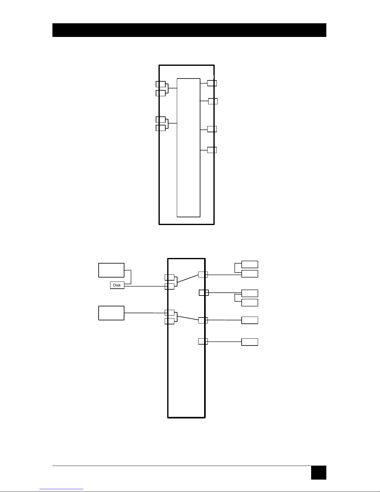
Ports A and B are fully bi-directional to ports 1, 2, 3, and 4 (see Figure 2-1). You
determine where to connect computers, host adapters, and peripherals. In
general, if daisy-chained ports are required for connection to external peripherals,
use ports A or B. See Figure 2-2 for a typical installation.
Page 16
13
CHAPTER 2: Installation
Figure 2-1. SCSI Matrix Switch block diagram.
Figure 2-2. Typical installation.
Computer
Tape
Disk
Term
Computer
Term
Term
Term
Disk
CD-Rom
Term
Scanner
Term
Scanner
Term
1
2
4
3
B
B
A
A
Term
124
3
B
B
A
A
S
W
I
T
C
H
M
A
T
R
I
X
Term
Term
Term
Term
Term
SCSI Switch Ports
S
w
i
t
c
h
M
a
t
r
i
x
Term
Term
Term
Term
Term
Term
Page 17

14
4 X 2 SCSI MATRIX SWITCH
NOTE
1. Connections can be made to either connector on the appropriate port.
2. “Term” indicates where terminators should be installed.
The LCD panel is used to select port connections and enable or disable each
internal SCSI port terminator. Refer to Chapter 4 for complete instructions on
operating the LCD keypad.
You can selectively enable or disable any internal terminator to meet system
configurations and requirements.
NOTE
For proper operation of any SCSI bus, there must not be a “hanging”
line or cable. Termination should be enabled on active SCSI ports that
are not connected through to another port.
Page 18

15
CHAPTER 3: Installation
3. Installation
3.1 What’s Included
• This users’ manual
• (1) 4 x 2 SCSI Matrix Switch
• (1) AC power cable (110 or 220 V)
• (1) 10-ft. (3.1-m) 9-Pin-male-to-9-pin-female RS-232 cable
• (1) 9-pin-male-to-25-pin-female RS-232 adapter
• (2) SCSI Matrix Switch control software disks
• Rackmount handles and screws
• Bottom feet
If anything is missing or damaged, call Black Box at 724-746-5500.
3.2 AC Line Voltage
You can connect the Switch to any AC input voltage between 105 to 240 volts.
Unless otherwise specified, the Switch will be shipped with a 110-volt power cord
for use in the USA. For a power cord that will work in your country (outside the
USA), call Black Box Technical Support.
3.3 Switch Placement
Place the Switch in a convenient location near the host computer or peripherals.
Keep SCSI cable lengths short to provide the best performance and reliability.
Make sure that the dual fans and ventilation slots on the sides of the Switch receive
adequate airflow. Do not place the Switch on any devices that generate excessive
heat.
3.4 Power Equipment Off
Power off all equipment and peripherals connected to the SCSI interface before
installing cables or terminators.
Page 19

16
4 X 2 SCSI MATRIX SWITCH
3.5 SCSI Interface Cabling
Both versions of the 4 x 2 SCSI Matrix Switch have 68-pin shielded high-density
SCSI-2 connectors. Single-ended devices can have cable lengths up to 19 ft. (6 m).
Differential devices can be connected with up to 82 feet (25 meters) of cable. Lowvoltage differential devices can support up to 82 feet (25 meters) of cable.
Connect the host adapter or peripheral to the rear-panel connector using a
proper SCSI cable. Section 6.1 describes standard SCSI cable interface
requirements.
NOTE
Do not intermix single-ended and differential devices on any SCSI chain
unless a SCSI differential converter is used to convert from one bus
type to the other.
Figure 3-1. The SCSI Switch’s rear panel.
Page 20

17
CHAPTER 4: Operator Controls and Indicators
4. Operator Controls and
Indicators
4.1 AC Power Switch
The AC power switch is located on the Switch’s rear panel. Putting the switch in
the “1” position applies power to the SCSI Switch.
NOTE
Always apply AC power to the SCSI Switch before powering SCSI
devices and computers. This will ensure that devices are found on
system bootup.
4.2 LCD Display, Keypad, and Indicators
4.2.1 LCD D
ISPLAY
The LCD display shows the selection parameters available.
Figure 4-1. LCD display main menu.
> SET TEMP LIMIT
DISPLAY VERSION
DISPLAY POWER TEMP
FRONT PANEL LOCK
> SET SERIAL PORTS
SET SWITCH NUMBER
SET PORTS
> SET TERMINATION
DISPLAY PORTS
DISPLAY ACTIVITY
Page 21

18
4 X 2 SCSI MATRIX SWITCH
4.2.2 K
EYPAD
The Keypad enables the selection of menu and set-up parameters for the SCSI
Switch.
• MENU: Returns to the SCSI Switch set-up and configuration menu.
• ENTER: Selects the highlighted set-up parameter.
• UP, DOWN, RIGHT, LEFT Arrows: Scrolls the cursor to enable menu
selection.
4.2.3 I
NDICATORS
The indicators provide SCSI Switch status information.
• POWER: Identifies that the SCSI Switch is powered.
• BUSY: Identifies that there is SCSI activity on one or more SCSI ports.
• ALARM: A visual and audible alarm identifies a failure of an internal power
supply or that the SCSI Switch has exceeded the set temperature limit.
NOTE
To disable the audible alarm, press the front-panel MENU key. The
ALARM light will remain lit until the condition is corrected.
4.3 LCD Display Control Menus
SET PORTS
SET TERMINATION
SET TERMINATION
|A *| B|
|1|2||3 *|4|
SET PORTS
1234
A|*||||
B ||*|||
Page 22

19
CHAPTER 4: Operator Controls and Indicators
DISPLAY PORTS
SET SERIAL PORTS
SET SWITCH NUMBER
DISPLAY POWER, TEMPERATURE
SET TEMP LIMIT
SET TEMP LIMIT
MAX +40°C
CURRENT TEMP +26.0°C
DISPLAY POWER TEMP
PWR SUPPLY GOOD
+25.5°C
SET SWITCH NUMBER
01
USE UP/DOWN KEYS
SET SERIAL PORTS
COM 1 9600 * 19200
COM 2 9600 * 19200
DAISY CHAIN Y * N
DISPLAY PORTS
| A 1 | A 2 | A 3 | A 4 |
| B 1 | B 2 | B 3 | B 4 |
Page 23

20
4 X 2 SCSI MATRIX SWITCH
DISPLAY BUS ACTIVITY
FRONT PANEL LOCK
DISPLAY VERSION
HVD/ LVD/SE: Indicates current SCSI bus interface mode.
x: Indicates Serial Port Locked.
LAN: Indicates LAN Port installed and active.
4.4 SCSI Switch Port Configuration
The SCSI Switch has an internal memory device that retains the last configuration
and set-up information. Switch port, termination, serial port, and control
parameters are saved as they are entered on the front panel.
BLACK BOX
SC123A
S/N 2 1 0 0 3 0 3
H V D V E R 2 1 1 2 1 2 4 L A N
FRONT PANEL UNLOCKED
ENTER PASSWORD
TO LOCK 0 0 0 0
DISPLAY ACTIVITY
1 2 3 4
Page 24

21
CHAPTER 4: Operator Controls and Indicators
4.5 SCSI Switch Default Configuration
The SCSI Switch default configuration as shipped from the factory is defined
below.
PORTS: A1, B2
TERMINATION: All Off
SERIAL PORTS: 9600 Baud, Daisychained
SWITCH NUMBER: 01
TEMPERATURE ALARM: 40° Celsius
FRONT PANEL: Unlocked, Password 0000
Page 25

22
4 X 2 SCSI MATRIX SWITCH
5. Configuration and Operation
5.1 SCSI Cable Interface Requirements
The 4 x 2 SCSI Matrix Switch can be installed at any point on the SCSI bus. Always
use high-quality SCSI-2 or SCSI-3 cables for optimum computer performance and
reliability.
The SC123A differential switch contains 68-pin high-density SCSI-2 connectors
for 40MBps wide Ultra SCSI computers and peripherals. The maximum cable
distance should not exceed 82 ft. (25 m).
The SC122A single-ended/low-voltage differential switch contains 68-pin
high-density SCSI-2 connectors.
Low-Voltage Differential (LVD):
When operating with LVD devices, 80-MBps wide Ultra2 SCSI computers and
peripherals are supported. The maximum cable distance for LVD should not
exceed 25 meters (82 feet) total length.
Single-ended (SE):
When operating with SE devices, 40-MBps wide Ultra SCSI computers and
peripherals are supported. The maximum cable distance for SE should not exceed
6 meters (19.7 feet) total length.
Black Box offers standard and custom SCSI cables for connecting the SCSI
Switch to host devices and peripherals. Call Black Box Technical Support for
details.
5.2 Internal Terminator Selection
The SCSI Switch contains internal SCSI bus terminators for each port.
Termination is required at both ends of a SCSI bus for proper operation. Each
port can have their internal terminator enabled or disabled from the front-panel
display and keypad.
Refer to Figure 5-1 to select internal termination.
NOTE
Data errors will result if more than two sets of terminators are installed
on any SCSI bus (See Figures 2-1 and 2-2).
Page 26

23
CHAPTER 5: Configuration and Operation
5.3 Selecting Internal Terminator Power
On-board SCSI Switch terminators can be powered by internal 5-volt power or
externally from SCSI bus “termination power.”
Figure 5-1. Internal terminator power jumpers.
Table 5-1. Jumper settings for internal termination
E1-Port A E5-Port 1 E7-Port 3
E2-Port B E6-Port 2 E8-Port 4
NOTE
The standard factory default connects internal terminators to internal
5 volts.
5.4 Selecting External Terminator Power
The SCSI Switch can supply external terminator power via an internal resettable
fuse. This fuse supplies 1 amp at 5 volts to the termination power signal. The SCSI
Switch contains internal protection and will not be affected if other SCSI devices
provide terminator power.
Figure 5-2. External terminator power jumpers.
NOTE
Factory Default is “Enabled” on all ports.
E19-E28
E1-E8
Internal 5V
External
Termination
Power
Page 27

24
4 X 2 SCSI MATRIX SWITCH
Table 5-2. Jumper settings for external termination
E19-Port A E20-Port 1 E24-Port 3
E21-Port B E22-Port 2 E26-Port 4
NOTE
The standard factory default connects internal terminators to internal
5 volts.
5.5 Serial Port Interface Pinout
The SCSI Switch contains two RS-232 serial ports, using DB9 female connectors;
these allow external control of the switch. The connectors are compatible with
standard RS-232 modem cables. The serial ports can be configured to operate
separate communications ports or as daisy-chained ports.
Daisy-chained mode allows one computer or terminal to communicate with
multiple SCSI Switches.
Table 5-3. Rear-panel RS-232 connector pinout
Signal Description DB9 Pin DB25 Pin
DCD Data Carrier Detect 1 8
RXD Receive Data 2 3
TXD Transmit Data 3 2
DTR Data Terminal Ready 4 20
GND Signal Ground 5 7
DSR Data Set Ready 6 6
RTS Request to Send 7 4
CTS Clear to Send 8 5
RI Ring Indicator 9 22
5.6 Internal RS-232 Jumper Block
RS-232 P
ORT
1
Jumper block E9, E10, E1, E12, and E13 configure the Port 1 serial interface for
normal and null-modem serial cables. The SCSI Switch default configuration
operates with standard modem cables.
Page 28

25
CHAPTER 5: Configuration and Operation
Figure 5-3. RS-232 Port 1.
NOTE
To bypass RTS and CTS control signals, jumper E12-1 and E13-1. (This
may be required in some DOS applications.)
RS-232 P
ORT
2
Jumper block E14, E15, E16, E17, and E18 configure the Port 2 serial interface for
daisychained or dual serial ports. The SCSI Switch default configuration operates
with standard modem cables.
Figure 5-4. RS-232 Port 2.
NOTE
To bypass RTS and CTS control signals, jumper E17-1 and E18-1. (This
may be required in some DOS applications.)
5.7 RS-232 Serial Port Commands
The SCSI Switch can be controlled via the RS-232 interface using simple ASCII
control characters. The following information provides the parameters necessary
to control and select SCSI ports using any standard serial interface.
DAISY CHAINED DUAL SERIAL PORTS
E15
E16
E17
E18
RXD
TXD
RTS
CTS
E14
Page 29

26
4 X 2 SCSI MATRIX SWITCH
a. Baud rate internally selected for 9600 or 19200 baud. (Factory default is 9600
baud.)
b. Transmit and receive set for 8 data bits, 1 stop bit, no parity.
c. Serial interface operates in half-duplex mode.
d. i.e.: MODE COMx 9600,N,8,1
The sequence for communicating with the SCSI Switch is defined as:
a. Start sequence:
ascii “cr”,”/”, “/”
b. Switch box number:
Box 1 - “7C” ( | ) Box 3 - “7E” ( ~ )
Box 2 - “7D”( } ) Box 4 - “7F” ( del )
c. Port Select:
Port A1 - “A1” Port B1 - “B1”
Port A2 - “A2” Port B2 - “B2”
Port A3 - “A3” Port B3 - “B3”
Port A4 - “A4” Port B4 - “B4”
NOTE
1. More than one port can be selected when transmitting to port A or B.
(For example, to select A1, A3, B2, and B4, transmit “A13B24”.)
2. “0” clears all ports (for example, “A0” clears all ports connected to
port A).
d. Transmit Data to SCSI Switch:
Ascii “K” - Selects desired ports.
NOTE
If a port (A or B) is not specified, no action will be taken to that port. If a
port is selected (A1), that port will be selected and other A ports (2, 3,
and 4) will be turned off.
Page 30

27
CHAPTER 5: Configuration and Operation
Ascii “N” - Turns specified port ON.
Ascii “F” - Turns specified ports OFF.
e. End sequence:
Ascii “cr”
Table 5-4. SCSI Switch commands
Command Command Example Response
Character
Select Port K <cr>//|A1K<cr>
Report Port Status S <cr>//|S<cr> <abcdefgh>
Select Terminator k <cr>//}A1k<cr>
Report Terminator Status s <cr>//|s<cr> <ABCD123456>
Lock Front Panel L <cr>//|L<cr>
Unlock Front Panel U <cr>//|U<cr>
Report Model, S/N, and ? <cr>//|?text…<cr> <text…>
date of manufacture
Report Alarm Status A <cr>//|A<cr> <axyz>
Report Temperature T <cr>//|T<cr> <t+23.5>
(Celsius)
Report Performance P <cr>//|P<cr> <PAABBCCDD>
112233445566
Report SCSI Bus I <cr>//|I<cr> <xxxx>
Inactivity
Yank on SCSI Reset Y <cr>//|AC3Y<cr>
line
Page 31

28
4 X 2 SCSI MATRIX SWITCH
Table 5-4 (continued). SCSI Switch commands
Command Command Example Response
Character
Disable Audible Alarm OA <cr>//|OA<x><cr>
Set Baud Rate OB <cr>//|OB<xy><cr>
Set Serial Port Mode OC <cr>//|OC<x><cr>
Set Switch Number OD <cr>//|OD<xx><cr>
Set Lock/Unlock OP <cr>//|OP<xxxx><cr>
Password
Set Temperature Limit OT <cr>//|OT<xx><cr>
Report Revision R <cr>//|R<cr> <2024610>
Lock Serial Ports (LAN) OL <cr>//|OLxxxx<cr> //|OL1<cr>pass
//|OL0<cr>fail
Unlock Serial Ports OU <cr>//OUxxxx<cr> //|OU1<cr>pass
//|OU0<cr>fail
Report Serial Port OS <cr>//|OS<cr> //|OS1<cr>lock
Lock Status //|OS0<cr>open
Page 32

29
CHAPTER 5: Configuration and Operation
E
XPANDEDLIST OFCOMMANDS
a. Select SCSI Port Matrix:
command: <cr>//|<AB1234K><cr>
report: none
NOTE
K - Forces switch patterns to outputs.
N - Turns the specified switches ON.
F - Turns the specified switches off.
b. Report SCSI Port Matrix Assignment Status
command: <cr>//|S<cr>
report: //|A1234B1234K<cr>
c. Select SCSI Terminator Matrix:
command: <cr>//|<AB1234k><cr>
report: none
d. Report SCSI Terminator Status
command: <cr>//|s<cr>
report: //|AB1234k<cr>
e. Report Model, Serial Number, and Date of Manufacture:
command: <cr>//|?<cr>
report: //SC121A 20241150 01/15/2000
SC122A = model number
20241150 = serial number
01/15/2000 = date of manufacture
Page 33

30
4 X 2 SCSI MATRIX SWITCH
f. Report Alarm Status:
command: <cr>//|a<cr>
report: //|axyz<cr> (xx- 8-bit hexadecimal value)
x: 1 = Over temperature
y: 1 = Power supply 2 failure
z = Power supply 1 failure
g. Report SCSI Bus Performance:
command: <cr>//|P<xy><cr>
report: //|P<aabb11223344<cr>
aa: hex 00-FF Port A
bb: hex 00-FF Port B
hex 00 = 0% Busy
hex FF = 100% Busy
h. SCSI bus Inactivity to SCSI report:
command: <cr>//|I<cr>
report: xxxx: hex inactive time in tenths of seconds
i. Yank on SCSI Reset line:
command: <cr>//|<AB1234Y><cr>
report: none
j. Disable Audible Alarm:
command: <cr>//|OA<x><cr>
x: 0= don’t disable
x: 1=disable alarm
report: none
Page 34

31
CHAPTER 5: Configuration and Operation
k. Set Serial Port Baud Rate:
command: <cr>//|OB<xy><cr>
x: 0= COM1
x: 1=COM2
y: 0=9600 Baud
y: 1=19200 Baud
report: none
l. Set Serial Port Mode:
command: <cr>//|OC<x><cr>
x: 0= daisy chain serial ports
x: 1= dual comm serial ports
report: none
m. Set Switch (Device) Number:
command: <cr>//|OD<xx><cr>
xx: 01 thru 32
report: none
n. Set Lock/Unlock Front Panel Password:
command: <cr>//|OP<xxxx><cr>
xx: 000 thru 9999
report: none
o. Set Temperature Limit:
command: <cr>//|OT<xx><cr>
xx: 15 thru 55 (degrees C)
report: none
Page 35

32
4 X 2 SCSI MATRIX SWITCH
5.8 ASCII Character Reference for SCSI Switch Box Selection
Switch 12345678
ascii | } ~ (del) ` a b c
Switch 9 10 11 12 13 14 15 16
ascii d e f g h i j k
Switch 17 18 19 20 21 22 23 24
ascii l m n o p q r s
Switch 25 26 27 28 29 30 31 32
ascii t u v w x y z {
5.9 Graphical User Interface (GUI)
Your SCSI Switch is supplied with control software that is compatible with
Windows
®
95, 98, and Windows NT®operating systems to allow remote control of
the switch. Follow instructions on the disks to install the software.
Figure 5-5. Screen shot of GUI control panel.
Settings
Black Box Control Software Version 3.1
4 x 2 SCSI Matrix Switch
Port Assignments
A
B
1 2 3 4
Terminators
A
B
Terminators
1 2 3 4
Backup - RAID #1
Bus Mode
HVD
LVD
SE
Smart Switching
Ports
Terminators
Show Bus Activity Meters
Port Busy
1 2 3 4
100
%
0
1 2 3 4
Backup - RAID #1
SCSI Busy
Alarm
Switch Without
Holdoff
File Configure SC122/123A Window Help
Page 36

33
CHAPTER 5: Configuration and Operation
5.10 Connecting Multiple SCSI Switches
Up to 32 SCSI Switches can be controlled by a single RS-232 serial interface. To
operate in this configuration, set the serial ports to operate in daisy-chained mode.
Figure 5-6. Multiple SCSI Switch configuration.
5.11 Rackmount Installation
The SCSI Switch can be installed in a standard 19-inch (EIA unit) rack.
5.11.1 I
NSTALLATION INRACK
Attach the two mounting brackets to each side of the SCSI Switch enclosure using
the screws provided. Set the unit into position on the rack, aligning the mounting
bracket holes with the rack holes. Use
5
⁄8-inch 10-32 to 12-24 screws to install the
Switch in the rack.
5.11.2 R
ACKMOUNTCONSIDERATIONS
1. For proper operation, ensure that the maximum recommended operating
ambient temperature of 149°F (65°C) is not exceeded.
2. If the unit is installed in a closed or multi-unit rack assembly, the operating
ambient temperature of the rack environment may be greater than room
ambient. Install the rack in an environment compatible with SCSI Switch
maximum rated operating temperature.
3. Make sure the amount of airflow around the SCSI Switch required for safe
operation is not compromised.
Computer
SCSI Switch
Box 1
SCSI Switch
Box 2
SCSI Switch
Box 3
SCSI Switch
Box 4
Page 37

34
4 X 2 SCSI MATRIX SWITCH
4. Mounting the SCSI Switch in a rack should not cause a hazardous condition
of uneven mechanical loading.
5. Do not overload the SCSI Switch supply circuit.
6. Make sure the rackmount equipment is connected to earth ground.
5.12 SCSI Switch Typical Applications
The following illustrations provide sample application and configuration
information. Many other configurations are possible with the SCSI Switch.
Figure 5-7. Sample application #1.
SCSI Switch
CD Towers
Servers
Server
Page 38

35
CHAPTER 5: Configuration and Operation
Figure 5-8. Sample application #2.
5.13 Network Control of SCSI Switch (Optional)
The 4 x 2 SCSI Matrix Switch may be controlled over a TCP/IP network using the
optional LAN port.
5.13.1 LAN P
ORTCONFIGURATION
If the SCSI Switch is equipped with the optional LAN port, you can remotely
control the SCSI Switch via a standard 10-Mbps Ethernet connection running
TCP/IP. The RS-232 COM2 port (which is used for daisy chaining SCSI Switches)
has been disabled (it is being used internally by the LAN card). If you wish to daisy
chain SCSI Switches you’ll need to disable the LAN port and enable the COM2
port. To do this, you’ll need to configure jumper block E15 and E16 as shown in
Figure 5-9 (RS-232 ENABLED) and remove the ribbon cable from J14 (see Figure
5-10) as shown in following configurations.
5.13.2 C
FGSWITCHUTILITY
The cfgswitch.exe utility is used to configure the TCP/IP address. This utility is
provided on the included disk. You can re-configure the IP address by using the IP
Configuration Utility. Run cfgswitch.exe from the diskette provided with your 4 x 2
SCSI Matrix Switch. A “Configure Black Box Network Switch” window will appear.
Enter the new IP address and switch MAC address in the appropriate fields. The
MAC address can be found on a label located on the bottom of the Switch. You can
search for the IP address by clicking the search button in the “Configure Black Box
Network Switch.” This will bring up a “Search For Black Box Network Switches”
window. Enter a beginning IP address, an ending IP address, and click Search.
SCSI
Switch
Terminals
Hosts
Hosts
Page 39
36
4 X 2 SCSI MATRIX SWITCH
Command strings to control the SCSI Switch may be manually entered through
certain versions of HyperTerminal to support connections to IP addresses via LAN.
NOTE
You will need to specify port #3001 when establishing the connection.
Figure 5-9. SCSI Switch LAN/RS-232 jumper configuration.
OR
123
RXD
TXD
RTS
CTS
E18
E17
E16
E15
LAN ENABLED (DEFAULT) RS-232 ENABLED
123
RXD
TXD
RTS
CTS
E18
E17
E16
E15
Page 40

37
CHAPTER 5: Configuration and Operation
Figure 5-10. J14: LAN ribbon cable location.
Figure 5-11. Configure network switch screens.
4340052
Ethernet Addresses
1. 00-80-a3-2b-9c-74
REV A13
Search for Network Switches
Starting IP Address
. . .
Ending IP Address
. . .
CancelOK
Search
New IP Address
. . .
Configure Exit
Initialize IP Address
Switch MAC Address
. . .
Change IP Address
00 – 80 – A3 – – –
Configure Network Switch
Current IP Address
Search
J14
Page 41

38
4 X 2 SCSI MATRIX SWITCH
5.13.3 S
ETSWITCHUTILITY
The setswitch.exe utility enables you to set switch parameters via the LAN port.
This utility is located on the diskette provided with your SCSI Switch. To change
switch settings and termination for an SCSI Switch: from a DOS prompt run
SETSWITCH.EXE from the diskette provided.
Usage:
setswitch [/?] [/i<IP Address>] [/c<Com Port>] [/b<baud rate>]
[/n<Switch Number>] [/h<holdoff>] [/x] [/t<Termination>]
[[/s]<SwitchSettings>] [/w<command>] [/r<command>]
Where:
/? = this message.
/i <IPAddress> = The IP address of the network-enabled SCSI Switch.
/c <Com Port> = The number of the Com Port to address (1 to 8;default=1).
/b <Baud Rate> = The baud rate for the com port (2400, 9600, 19200;
dflt=9600).
/n <Switch Number> = The number of the switch to change (1 to 32; default=1).
/h <holdoff> = SCSI Bus holdoff, in seconds. The SCSI Switch will not change
the switch settings on a bus until there has been inactivity the specified
number of seconds. Valid range is 0 to 25 seconds.
/x = Ignore SCSI Bus activity. Switch settings will be changed immediately.
/t <Termination> = Termination can be turned on or off for each port (A or B,
or 1 to 4). “A2NB3F” activates termination for ports A and 2 and, it
deactivates termination on ports B and 3. Termination on unspecified ports
will not be affected.
[/s]<Switch Settings> = The settings to be changed (/s is optional).
“A1B2NB1A2F” connects ports A1 and B2 and disconnects ports B1 and A2.
Switch settings on unspecified ports will not be affected.
[/w]<command> = <command> is sent to the switch with no parsing. Any
response from the switch is ignored.
Page 42

39
CHAPTER 5: Configuration and Operation
[/r]<command> = <command> is sent to the switch with no parsing. Any
response from the switch is displayed on the console’s error output.
Page 43

40
4 X 2 SCSI MATRIX SWITCH
6. SCSI Technical Information
6.1 SCSI Basics
6.1.1 SCSI-1
The original specification supports data transfers up to 5 MBps on an 8-bit wide
parallel data bus. SCSI-1 standards had some incompatibility problems between
host adapters and peripheral devices. The need to improve compatibility, increase
transfer rates, and add other features for better performance required a review of
the specifications.
6.1.2 SCSI-2
Improved compatibility and higher transfer rates were provided in this
enhancement. The addition of Wide SCSI permits 16 or 32 bits to be transferred in
parallel, the latter requiring two cables. In combination with the Fast SCSI option,
synchronous data transfers up to 10 MBps for 8 bit, 20 MBps for 16 bit, and 40
MBps for 32 bit were achieved.
6.1.3 SCSI-3
The most significant additions include the ability to address up to 32 devices, a 16bit single cable data bus, and serial SCSI protocol. The SCSI-3 standard has been
split into several subdocuments, including the SCSI Parallel Interface (SPI) which
is based on a layered protocol and the SCSI Interlocked Protocol (SIP), a software
link protocol.
6.1.4 S
IGNALWIRING
The signal wiring used in a SCSI bus has an impact on bus performance. The two
wiring techniques generally used for SCSI are single-ended and differential. With
single-ended wiring, a single wire carries the signal from initiator to target. Singleended circuitry is not noise resistant and is generally limited to about 6 meters
(20 ft.) at data transfer speeds of 10 MB.
Differential wiring uses two wires for each signal and offers exceptional noise
resistance because it does not rely on a common ground. This allows cables up to
25 meters (82 ft.) and reliable operation at 10 MB or greater. Differential wiring
and circuitry is more complex than single-ended and generally tends to be more
expensive to implement.
Page 44

41
CHAPTER 6: SCSI Technical Information
6.1.5 C
OMMONPROBLEMS
The majority of problems encountered with SCSI bus installations are due to
unbalanced or improper impedances on the SCSI bus transmission cables caused
by varying manufacturers’ peripheral devices. SCSI terminators compensate for
these inherent impedance mismatches on a SCSI bus where peripheral devices
such as hard drives, CD-ROM drives, scanners, or printers are used.
6.1.6 P
ASSIVE
T
ERMINATORS
The most basic is a passive-resistance style terminator. This is usually supplied with
peripherals and frequently does a poor job of balancing the impedance of the
SCSI bus. Passive terminators are resistor networks that allow signal voltages to vary
with the load and terminator power supplied, resulting in unstable signals from
end to end on the bus and causing data errors. Passive terminators are no longer
recommended by ANSI for designs.
6.1.7 A
CTIVETERMINATORS
Active terminators add a voltage regulator to the circuit to regulate signal voltages
with varying loads and termpower, allowing a consistent signal to be transmitted
everywhere on the bus. This in turn compensates for the varying bus lengths and
signal loads. All lines are terminated through 110-ohm resistors, which are
applicable to all narrow and wide single-ended applications. Active termination is
the minimum ANSI-recommended termination.
6.2 SCSI Installation Tips
• Keep your SCSI chain short. Official SCSI specifications limit a SCSI chain to no
more that 19.7 feet (6 meters) long. Practical experience says the shorter, the
better. The maximum length you should allow between devices is 3 feet
(0.9 m).
• Never assign the same SCSI ID number to two devices residing on the same bus. SCSI
uses these numbers as addresses to ensure that information goes to the correct
location. Giving two devices the same address can result in lost information.
• Know that some SCSI-ID numbers may be reassigned. Internal boot hard drives are
usually set to ID “0” while secondary hard drives are set to “1.” Motherboards
or host adapters are generally set to ID “7.”
• Always terminate the first and last devices on the chain. Drives purchased specifically
for internal use nearly always arrive with terminators installed. If in doubt, call
the vendor you purchased the device from.
Page 45

42
4 X 2 SCSI MATRIX SWITCH
• If the last device on the chain has two SCSI connectors, attach the cable to one and a
terminator to the other. Otherwise, you’ll have an open connector that may cause
noise on the SCSI chain.
• Always turn off the power to your computer and SCSI devices before swapping cables or
moving devices around. SCSI cables contain sensitive data transmission lines and
one or more live power wires.
• Turn on your SCSI devices before you turn on the computer. Some SCSI devices will
not mount if they are not running when you power up your computer.
Shutting down your computer first and then the attached SCSI devices allows
your system to completely “flush” itself.
6.3 SCSI Interface Signal Descriptions
A total of 18 signals are required for the SCSI interface. These signals are described
as follows:
• BSY (BUSY): An “OR-tied” signal indicating that the bus is being used.
• SEL (SELECT): An “OR-tied” signal used by an initiator to select a target or by
a target to reselect an initiator.
• C/D (CONTROL/DATA): A signal driven by a target that indicates whether
control or data information is on the data bus. True indicates control.
• I/O (INPUT/OUTPUT): A signal driven by a target that controls the
direction of data movement on the data bus with respect to an initiator. True
indicates input to the initiator. This signal is also used to distinguish between
selection and reselection phases.
• MSG (MESSAGE): A signal driven by a target during the message phase.
• REQ (REQUEST): A signal driven by a target to indicate a request for a
REQ/ACK data transfer handshake.
• ACK (ACKNOWLEDGE): A signal driven by an initiator to indicate an
acknowledgment for a REQ/ACK data transfer handshake.
• ATN (ATTENTION): A signal driven by an initiator to indicate the
ATTENTION condition.
• RST (RESET): An “OR-tied” signal that indicates the reset condition.
Page 46

43
CHAPTER 6: SCSI Technical Information
• DB(0 through 15,P,P1) (DATA BUS): Eight data-bit signals, plus a parity-bit
signal that form a data bus. DB(7) is the most significant bit and has the
highest priority during the Arbitration phase. Bit number, significance, and
priority decrease downward to DB(0). A data bit is defined as one when the
signal value is true and is defined as zero when the signal value is false. Data
parity DB(P) shall be odd.
Table 6-1. SCSI connector assignments single-ended (SE)
16-bit SCSI (wide)
Signal Name Pin Number Signal Name Pin Number
Ground 1 -DB12 35
Ground 2 -DB13 36
Ground 3 -DB14 37
Ground 4 -DB15 38
Ground 5 -DBP1 39
Ground 6 -DB0 40
Ground 7 -DB1 41
Ground 8 -DB2 42
Ground 9 -DB3 43
Ground 10 -DB4 44
Ground 11 -DB5 45
Ground 12 -DB6 46
Ground 13 -DB7 47
Ground 14 -DBP 48
Page 47

44
4 X 2 SCSI MATRIX SWITCH
Table 6-1 (continued). SCSI connector assignments
single-ended (SE) 16-bit SCSI (wide)
Signal Name Pin Number Signal Name Pin Number
Ground 15 Ground 49
Ground 16 Ground 50
TERMPWR 17 TERMPWR 51
TERMPWR 18 TERMPWR 52
Reserved 19 Reserved 53
Ground 20 Ground 54
Ground 21 -ATN 55
Ground 22 Ground 56
Ground 23 -BSY 57
Ground 24 -ACK 58
Ground 25 -RST 59
Ground 26 -MSG 60
Ground 27 -SEL 61
Ground 28 -C/D 62
Ground 29 -REQ 63
Ground 30 -I/O 64
Ground 31 -DB8 65
Page 48

45
CHAPTER 6: SCSI Technical Information
Table 6-1 (continued). SCSI connector assignments
single-ended (SE) 16-bit SCSI (wide)
Signal Name Pin Number Signal Name Pin Number
Ground 32 -DB9 66
Ground 33 -DB10 67
Ground 34 -DB11 68
Table 6-2. SCSI connector assignments differential/16-bit SCSI (wide)
Signal Name Pin Number Signal Name Pin Number
+DB(12) 1 -DB(12) 35
+DB(13) 2 -DB(13) 36
+DB(14) 3 -DB(14) 37
+DB(15) 4 -DB(15) 38
+DB(P1) 5 -DB(P1) 39
Ground 6 Ground 40
+DB(0) 7 -DB(0) 41
+DB(1) 8 -DB(1) 42
+DB(2) 9 -DB(2) 43
+DB(3) 10 -DB(3) 44
+DB(4) 11 -DB(4) 45
Page 49

46
4 X 2 SCSI MATRIX SWITCH
Table 6-2 (continued). SCSI connector assignments diff./16-bit SCSI (wide)
Signal Name Pin Number Signal Name Pin Number
+DB(5) 12 -DB(5) 46
+DB(6) 13 -DB(6) 47
+DB(7) 14 -DB(7) 48
+DB(P) 15 -DB(P) 49
DIFFSENS 16 Ground 50
TERMPWR 17 TERMPWR 51
TERMPWR 18 TERMPWR 52
Reserved 19 Reserved 53
+ATN 20 -ATN 54
Ground 21 Ground 55
+BSY 22 -BSY 56
+ACK 23 -ACK 57
+RST 24 -RST 58
+MSG 25 -MSG 59
+SEL 26 -SEL 60
+C/D 27 -C/D 61
+REQ 28 -REQ 62
Page 50

47
CHAPTER 6: SCSI Technical Information
Table 6-2 (continued). SCSI connector assignments
differential/16-bit SCSI (wide)
Signal Name Pin Number Signal Name Pin Number
+I/O 29 -I/O 63
Ground 30 Ground 64
+DB(8) 31 -DB(8) 65
+DB(9) 32 -DB(9) 66
+DB(10) 33 -DB(10) 67
+DB(11) 34 -DB(11) 68
Table 6-3. SCSI connector assignments
low-voltage differential (LVD)/16-bit SCSI (wide)
Signal Name Pin Number Signal Name Pin Number
+DB(12) 1 -DB(12) 35
+DB(13) 2 -DB(13) 36
+DB(14) 3 -DB(14) 37
+DB(15) 4 -DB(15) 38
+DB(P1) 5 -DB(P1) 39
+DB(0) 6 -DB(0) 40
+DB(1) 7 -DB(1) 41
+DB(2) 8 -DB(2) 42
+DB(3) 9 -DB(3) 43
Page 51

48
4 X 2 SCSI MATRIX SWITCH
Table 6-3 (continued). SCSI connector assignments
low-voltage differential (LVD)/16-bit SCSI (wide)
Signal Name Pin Number Signal Name Pin Number
+DB(4) 10 -DB(4) 44
+DB(5) 11 -DB(5) 45
+DB(6) 12 -DB(6) 46
+DB(7) 13 -DB(7) 47
+DB(P) 14 -DB(P) 48
Ground 15 Ground 49
DIFFSENS 16 Ground 50
TERMPWR 17 TERMPWR 51
TERMPWR 18 TERMPWR 52
Reserved 19 Reserved 53
Ground 20 Ground 54
+ATN 21 -ATN 55
Ground 22 Ground 56
+BSY 23 -BSY 57
+ACK 24 -ACK 58
+RST 25 -RST 59
+MSG 26 -MSG 60
Page 52

49
CHAPTER 6: SCSI Technical Information
Table 6-3 (continued). SCSI connector assignments
low-voltage differential (LVD)/16-bit SCSI (wide)
Signal Name Pin Number Signal Name Pin Number
+SEL 27 -SEL 61
+C/D 28 -C/D 62
+REQ 29 -REQ 63
+I/O 30 -I/O 64
+DB(8) 31 -DB(8) 65
+DB(9) 32 -DB(9) 66
+DB(10) 33 -DB(10) 67
+DB(11) 34 -DB(11) 68
Page 53

50
4 X 2 SCSI MATRIX SWITCH
Table 6-4. SCSI speed support map
STA Term Maximum Bus Length (M) Maximum Devices
SE HVD LVD
SCSI-1 6 25 - 8
Fast SCSI 6 25 - 8
Fast Wide SCSI 6 25 - 16
Ultra SCSI 1.5 25 - 8
Ultra SCSI 3 - - 4
Wide Ultra SCSI - 25 - 16
Wide Ultra SCSI 1.5 - - 8
Wide Ultra SCSI 3 - - 4
Ultra2 SCSI (1) 25 25 2
Ultra2 SCSI (1) 12 12 8
Wide Ultra2 SCSI (1) 25 25 2
Wide Ultra2 SCSI (1) 12 12 16
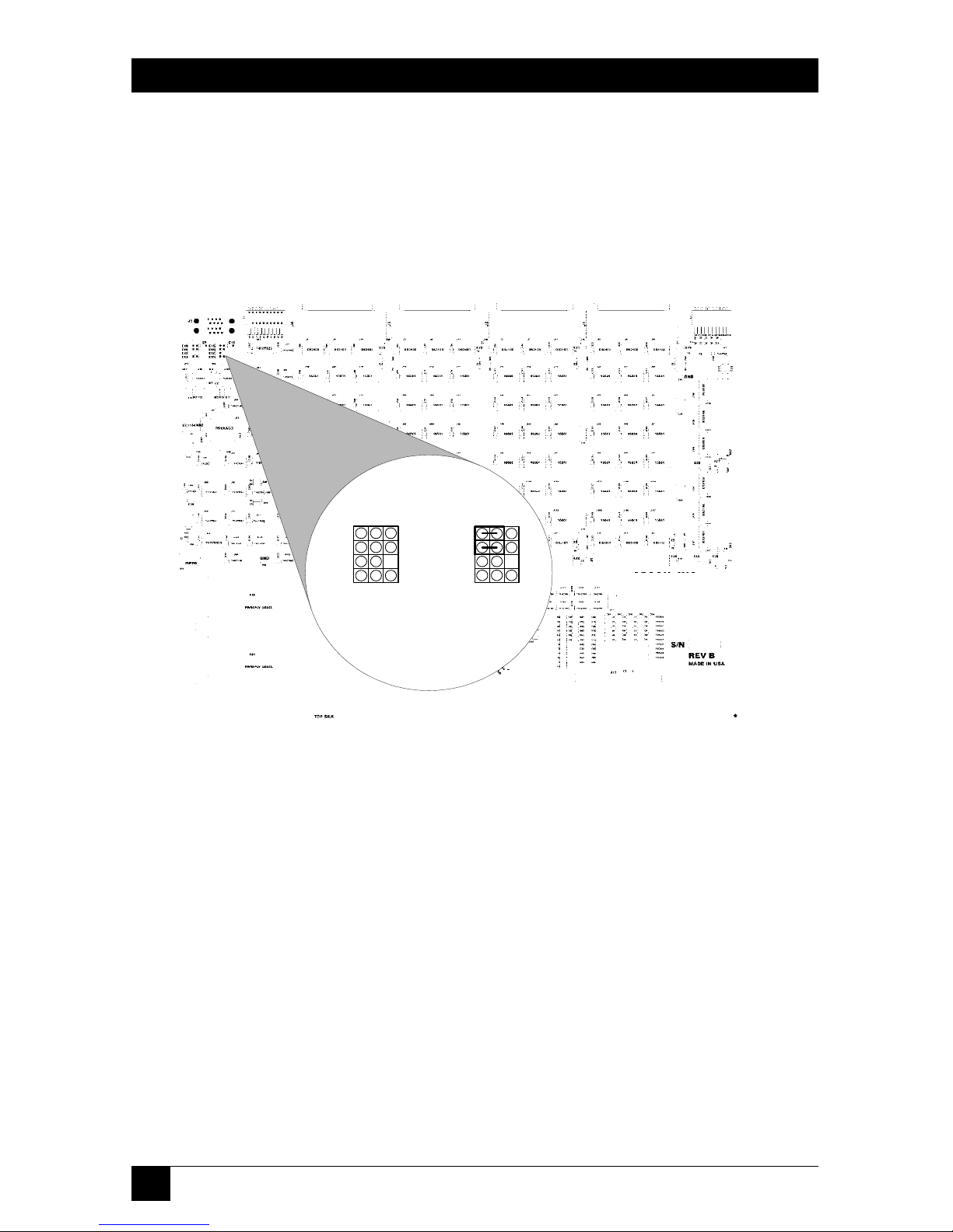
To access jumper options:
Remove the six screws on the bottom of the unit. Then lift off the cover.
Page 54

51
CHAPTER 6: SCSI Technical Information
Figure 6-1. SCSI Switch component placement.
• RS-232 jumper block: E9 through E18
• Active terminator power select: E1 through E8, E29, E30
Page 55

52
4 X 2 SCSI MATRIX SWITCH
7. Troubleshooting
7.1 Calling Black Box
If you determine that your 4 x 2 SCSI Matrix Switch is malfunctioning, do not
attempt to alter or repair the unit. It contains no user-serviceable parts. Contact
Black Box at 724-746-5500.
Before you do, make a record of the history of the problem. We will be able to
provide more efficient and accurate assistance if you have a complete description,
including:
• the nature and duration of the problem.
• when the problem occurs.
• the components involved in the problem.
• any particular application that, when used, appears to create the problem or
make it worse.
7.2 Shipping and Packaging
If you need to transport or ship your 4 x 2 SCSI Matrix Switch:
• Package it carefully. We recommend that you use the original container.
• If you are shipping the 4 x 2 SCSI Matrix Switch for repair, make sure you
include everything that came in the original package. Before you ship, contact
Black Box to get a Return Materials Authorization (RMA) number.
 Loading...