

Page 1
LES301A-KIT
LES301AE-KIT
1-Port 10/100 Device Server, RS-232/422/485, DB9 M
Access a serial RS-232 or RS-422/485 device over a
10- or 100-Mbps network.
• Remotely monitor, manage, and control an industrial device in the field.
• Easy to configure through a Web browser, serial console, Telnet™
or Windows® utility.
LES301A
Information
LES301A user manual
Customer
Support
Order toll-free in the U.S.: Call 877-877-BBOX (outside U.S. call 724-746-5500)
FREE technical support 24 hours a day, 7 days a week: Call 724-746-5500 or fax 724-746-0746
Mailing address: Black Box Corporation, 1000 Park Drive, Lawrence, PA 15055-1018
Web site: w ww.blackbox.com • E-mail: info @ blackbox.com
Page 2

724-746-5500 | blackbox.com
Trademarks Used in this Manual
Trademarks Used in this Manual
Black Box and the Double Diamond logo are registered trademarks of BB Technologies, Inc.
HP and OpenView are registered trademarks of Hewlett-Packard Development Company.
Intel and Pentium are registered trademarks of Intel Corporation.
MS-DOS, Microsoft, and Windows are registered trademarks of Microsoft Corporation.
Any other trademarks mentioned in this manual are acknowleged to be the property of the trademark owners.
Page 2
We‘re here to help! If you have any questions about your application
or our products, contact Black Box Tech Support at 724-746 -5500
or go to blackbox.com and click on “Talk to Black Box.”
You’ll be live with one of our technical experts in less than 30 seconds.
724-746-5500 | blackbox.com
LES301A user manual
Page 3

FCC and IC RFI Statements
Federal Communications Commission and Industry Canada Radio Frequency Interference
Statements
This equipment generates, uses, and can radiate radio-frequency energy, and if not installed and used properly, that is, in strict
accordance with the manufacturer’s instructions, may cause inter ference to radio communication. It has been tested and found to
comply with the limits for a Class A computing device in accordance with the specifications in Subpart B of Part 15 of FCC rules,
which are designed to provide reasonable protection against such interference when the equipment is operated in a commercial
environment. Operation of this equipment in a residential area is likely to cause interference, in which case the user at his own
expense will be required to take whatever measures may be necessary to correct the interference.
Changes or modifications not expressly approved by the party responsible for compliance could void the user’s authority to
operate the equipment.
This digital apparatus does not exceed the Class A limits for radio noise emis sion from digital apparatus set out in the Radio
Interference Regulation of Industry Canada.
Le présent appareil numérique n’émet pas de bruits radioélectriques dépassant les limites applicables aux appareils numériques de
la classe A prescrites dans le Règlement sur le brouillage radioélectrique publié par Industrie Canada.
LES301A user manual
724-746-5500 | blackbox.com
Page 3
Page 4

724-746-5500 | blackbox.com
NOM Statement
Instrucciones de Seguridad
(Normas Oficiales Mexicanas Electrical Safety Statement)
1. Todas las instrucciones de seguridad y operación deberán ser leídas antes de que el aparato eléctrico sea operado.
2. Las instrucciones de seguridad y operación deberán ser guardadas para referencia futura.
3. Todas las advertencias en el aparato eléctrico y en sus instrucciones de operación deben ser respetadas.
4. Todas las instrucciones de operación y uso deben ser seguidas.
5. El aparato eléctrico no deberá ser usado cerca del agua—por ejemplo, cerca de la tina de baño, lavabo, sótano mojado o cerca
de una alberca, etc.
6. El aparato eléctrico debe ser usado únicamente con carritos o pedestales que sean recomendados por el fabricante.
7. El aparato eléctrico debe ser montado a la pared o al techo sólo como sea recomendado por el fabricante.
8. Servicio—El usuario no debe intentar dar servicio al equipo eléctrico más allá a lo descrito en las instrucciones de operación.
Todo otro servicio deberá ser referido a personal de servicio calificado.
9. El aparato eléctrico debe ser situado de tal manera que su posición no interfiera su uso. La colocación del aparato eléctrico
sobre una cama, sofá, alfombra o superficie similar puede bloquea la ventilación, no se debe colocar en libreros o gabinetes
que impidan el flujo de aire por los orificios de ventilación.
10. El equipo eléctrico deber ser situado fuera del alcance de fuentes de calor como radiadores, registros de calor, estufas u otros
aparatos (incluyendo amplificadores) que producen calor.
11. El aparato eléctrico deberá ser connectado a una fuente de poder sólo del tipo descrito en el instructivo de operación, o como
se indique en el aparato.
12. Precaución debe ser tomada de tal manera que la tierra fisica y la polarización del equipo no sea eliminada.
13. Los cables de la fuente de poder deben ser guiados de tal manera que no sean pisados ni pellizcados por objetos colocados
sobre o contra ellos, poniendo particular atención a los contactos y receptáculos donde salen del aparato.
14. El equipo eléctrico debe ser limpiado únicamente de acuerdo a las recomendaciones del fabricante.
15. En caso de existir, una antena externa deberá ser localizada lejos de las lineas de energia.
16. El cable de corriente deberá ser desconectado del cuando el equipo no sea usado por un largo periodo de tiempo.
17. Cuidado debe ser tomado de tal manera que objectos liquidos no sean derramados sobre la cubierta u orificios de ventilación.
18. Servicio por personal calificado deberá ser provisto cuando:
A: El cable de poder o el contacto ha sido dañado; u
B: Objectos han caído o líquido ha sido derramado dentro del aparato; o
C: El aparato ha sido expuesto a la lluvia; o
D: El aparato parece no operar normalmente o muestra un cambio en su desempeño; o
E: El aparato ha sido tirado o su cubierta ha sido dañada.
Page 4
724-746-5500 | blackbox.com
LES301A user manual
Page 5

Table of Contents
Chapter Page
1. Specifications........................................................................................................................................................................7
1.1 Hardware Specifications ................................................................................................................................................7
1.2 Software Specifications .................................................................................................................................................7
1.3 DB9 Pin Assignments ....................................................................................................................................................8
1.4 Ethernet Port (RJ-45).....................................................................................................................................................8
1.5 Power Terminal Block Connector ..................................................................................................................................9
1.6 Buzzer/LED Message .....................................................................................................................................................9
1.6.1 Buzzer ............................................................................................................................................................ 9
1.6.2 LAN LED ..........................................................................................................................................................9
1.6.3 COM Port LED .................................................................................................................................................9
1.6.4 RUN LED ........................................................................................................................................................10
2. Overview ......................................................................................................................................................................11
2.1 Introduction ................................................................................................................................................................11
2.2 What’s Included ..........................................................................................................................................................11
2.3 Hardware Description .................................................................................................................................................11
2.4 Application Connectivity .............................................................................................................................................12
3. Hardware Setup .................................................................................................................................................................14
3.1 LED Indicators .............................................................................................................................................................14
3 .1.1 L AN L ED ........................................................................................................................................................14
3.1.2 COM Port LED ...............................................................................................................................................15
3.1.3 RUN LED ........................................................................................................................................................15
3.2 Installation Procedures (LES301A-KIT or LES301AE-KIT) ..............................................................................................15
4. Software Setup ..................................................................................................................................................................16
4.1 Configuration by SerialManager ..................................................................................................................................16
4 .1.1 St at ic I P ..........................................................................................................................................................16
4.1.2 Auto IP (Dynamic IP) ......................................................................................................................................17
4.2 Configuration by Telnet Utility .....................................................................................................................................18
4.2.1 Log into the System .......................................................................................................................................18
4.2.2 Networking ....................................................................................................................................................20
4.2.3 Change the Password ....................................................................................................................................21
4.2.4 COM1 Setup ..................................................................................................................................................21
4.2.5 Configure LES301A As a TCP Client .............................................................................................................. 23
4.2.6 Configure LES301A As a UDP Client ..............................................................................................................24
4.2.7 COM Port Setting ..........................................................................................................................................25
4.2.8 Enabling the Serial Data Buffer ......................................................................................................................25
4.2.9 Setting Packet Delimiter .................................................................................................................................26
4.2.10 Accept Control Command from COM POrt ...................................................................................................26
4.3 Configuration Using Web Browser ..............................................................................................................................26
4.3.1 Log in to the System ......................................................................................................................................27
4.3.2 Change the Password and RS-232/RS-485/RS-422 Type Selection ...............................................................28
4.3.3 Network Setup ..............................................................................................................................................29
4.3.4 Configure LES301A As a TCP Server ..............................................................................................................31
4.3.5 Configure LES301A As a TCP Client ...............................................................................................................32
4.3.6 Pair Connection .............................................................................................................................................33
4.4 Assign a New IP Address by ARP Command ..............................................................................................................35
LES301A user manual
724-746-5500 | blackbox.com
Page 5
Page 6

724-746-5500 | blackbox.com
Table of Contents
Chapter Page
5. Using VirtualCOM ...............................................................................................................................................................37
5.1 Setup of a Virtual COM Driver ...................................................................................................................................... 37
5.1.1 Pre-installation Requirements .......................................................................................................................... 37
5.1.2 Supported Firmware ....................................................................................................................................... 37
5.1.3 Limitation ........................................................................................................................................................ 38
5.1.4 Installation ......................................................................................................................................................38
5.1.5 Uninstalling .....................................................................................................................................................38
5.2 Virtual COM Communication .......................................................................................................................................38
5.2.1 Enable Virtual COM on LES301A .................................................................................................................... 38
5.2.2 Run Serial/IP for LES301A on PC .................................................................................................................... 39
5.3 Configuring Virtual COM Ports.....................................................................................................................................40
6. SNMP Setup ....................................................................................................................................................................... 42
6.1 SNMP Network Management Platform ........................................................................................................................ 42
6.2 Using NetworkView as an Example ..............................................................................................................................42
7. Start Writing Your Own Applications ..................................................................................................................................44
7.1 Preparing the System ....................................................................................................................................................44
7.2 Running the Sample Program ....................................................................................................................................... 44
7.2.1 TCPTEST in Visual Basic ...................................................................................................................................44
7.2.2 TCPTEST2 in Visual C ......................................................................................................................................45
8. Diagnostics .......................................................................................................................................................................46
8.1 Use Standard TCP/IP Utility Ping Command .................................................................................................................46
8.2 Use SerialManager Configuration Utility Program ........................................................................................................ 46
8.3 Use TCPTEST.exe or TCPTEST2.exe Sample Program .................................................................................................... 46
Appendix A: Upgrade System Firmware.....................................................................................................................................47
A.1 Upgrade Procedures ..................................................................................................................................................... 47
A.2 Critical Issues of Upgrading ..........................................................................................................................................48
A.3 Error Messages ............................................................................................................................................................. 48
Appendix B: Disable System Firmware ....................................................................................................................................... 49
Appendix C: Using SerialManager Utility ....................................................................................................................................50
C.1 SerialManager Utility Introduction ................................................................................................................................50
C.2 Interface .......................................................................................................................................................................50
C.3 Functions ...................................................................................................................................................................... 50
C.3.1 Device Search ................................................................................................................................................. 50
C.3.2 Firmware ......................................................................................................................................................... 53
C.3.3 Configuration .................................................................................................................................................. 55
C.3.4 Security ........................................................................................................................................................... 61
C.3.5 Virtual COM....................................................................................................................................................62
Page 6
724-746-5500 | blackbox.com
LES301A user manual
Page 7

Chapter 1: Specifications
1. Specifications
1.1 Hardware Specifications
Baud Rate — 1200 bps to 230 kbps
CPU — 16-bit embedded CPU, 100 MHz
Data Bits — 7, 8
EEPROM — 512 bytes
Flash Memory — 512 KB
Flow Control — None, Hardware CTS/RTS, Software X-ON/X-OFF
Host Communication — IEEE 802.3 baseband, TCP/IP, UDP, SNMP, HTTP, Telnet, ARP, BOOTP, DHCP, ICMP
Packet Delimiter — By intercharacter timeout, by characters delimiter
Parity — None, even, odd, mark, space
Reset — Built-in default key to restore factory settings
Stop Bits — 1, 2
SDRAM — 512 KB
Watchdog Timer — 1.34 second hardware auto reset, Power Failure Threshold: 4.75 V
SerialPort Communication — (1) RS-232 or RS-485/RS-422 selectable:
RS-232: EIA-RS-232C standard, full duplex, DB9;
RS-485: 2/4 wires, half/full duplex, terminal block;
RS-422: 4 wires, half/full duplex, terminal block
Connectors — (1) DB9 M, (1) 3-pin terminal block (power), (1) RJ-45, (1) 5-VDC power connector
Indicators — (3) LEDs: (1) Run, (1) LAN, (1) COM Port 1
Power — 9-30V terminal block, 2.8 watt
Temperature Tolerance — Operating: 32 to 140° F (0 to 60° C)
Humidity — 20-90%, noncondensing
Size — 1.1"H x 3.1"W x 2.6"D (2.8 x 7.8 x 6.5 cm)
1.2 Software Specifications
Configuration — Configuration information for both TCP/IP and serial ports is kept in the EEPROM;
Windows configuration utilities are provided for configuring settings
Protocol — TCP/IP, UDP, HTTP, SNMP, ARP, Telnet, ICMP, BOOTP, DHCP, SMTP
Internal Buffer Size — TCP receiving buffer size: 8 KB
TCP Transmitting Buffer Size — 16 KB
RS-232 or RS-485/RS-422 Receiving Buffer Size — 4 KB
RS-232 or RS-485/RS-422 Transmitting Buffer Size — 4 KB
LES301A user manual
724-746-5500 | blackbox.com
Page 7
Page 8
724-746-5500 | blackbox.com
Chapter 1: Specifications
1.3 DB9 Pin Assignments
Table 1-1 shows the LES301A unit’s DB9 connector pin assignments.
Table 1-1. DB9 connector pin assignments.
Pin RS-232 full-duplex 2-Wire RS- 485 half-duplex RS-422/4-Wire RS-485 full-duplex
1 DCD N/A N/A
2 RXD N/A TXD+
3 TXD DATA+ RXD+
4 DTR N/A N/A
5 SG (Signal Ground) SG (Signal Ground) SG (Signal Ground)
6 DSR N/A N/A
7 RTS DATA- RXD-
8 CTS N/A TXD-
9 N/A N/A N/A
NOTE: You may need an LES30X-TB5 adapter for RS-485 or RS-422 applications.
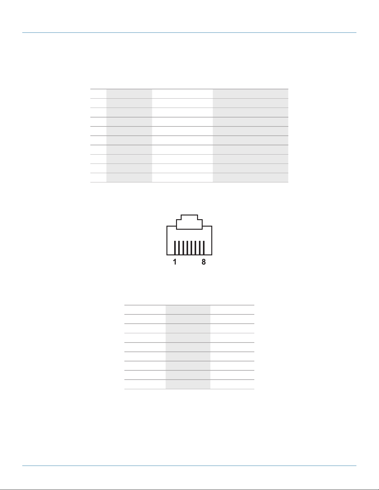
1.4 Ethernet Port (RJ-45)
Figure 1-1. RJ-45 connector pinout.
Table 1-2. RJ-45 connector pin assignment.
Pin Assignment 568A Definition 568B Definition
1 Green-White Orange-White
2 Green Orange
3 Orange-White Green-White
4 Blue Blue
5 Blue-White Blue-White
6 Orange Green
7 Brown-White Brown-White
8 Brown Brown
You can choose either 568A or 568B pinning. To make a crossover cable, use 568A pinning at one end of a UTP cable and use
568B pinning at the other end of the UTP cable.
Page 8
724-746-5500 | blackbox.com
LES301A user manual
Page 9
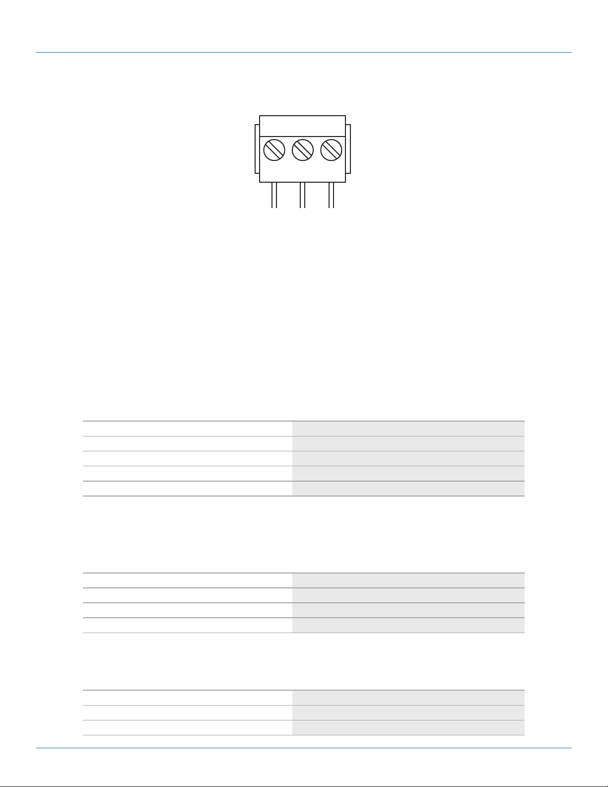
1.5 Power Terminal Block Connector
NOTE: VIN- and VIN+ can be reversed.
1.6 Buzzer/LED Message
Chapter 1: Specifications
F.G. VIN- VIN+
Figure 1-2. Terminal block signals.
1.6.1 Buzzer
“^”: Beep twice
“=”: Beep off
Table 1-3. Buzzer message.
Message Description
^===^===^===^===^===^===^…(1sec) Watchdog problem, contact Black Box Technical Support*
^^^^^^^^^^^^^^^^^^^^^^^^… Memory problem, contact Black Box Technical Support*
^==^========^^ (5sec) Startup OK but AP firmware is disabled
^==^========^^^ (5sec) Startup OK and AP firmware is enabled
*Contact Black Box Technical Support at 724-746-5500 or info@blackbox.com.
1.6.2 LAN LED
Table 1-4. LAN LED.
Message Description
LED off Ethernet is disconnected
LED is blinking green Data is transmitted at 100 Mbps on Ethernet
LED is blinking orange Data is transmitted at 10 Mbps on Ethernet
1.6.3 COM Port LED
Message Description
LED off No data is being transmitted on COM por t
LED is blinking Data is being transmitted on COM port
LES301A user manual
Table 1-5. COM port LED message.
724-746-5500 | blackbox.com
Page 9
Page 10

724-746-5500 | blackbox.com
Chapter 1: Specifications
1.6.4 RUN LED
Message Description
LED on Jumper JP1 Pin 1 and Pin 2 are short; this disables AP firmware in flash memory
LED is blinking at the rate once every 0.5 sec AP firmware is running
Table 1-6. RUN LED.
Page 10
724-746-5500 | blackbox.com
LES301A user manual
Page 11

Chapter 2: Overview
2. Overview
2.1 Introduction
The LES301A Ethernet Serial Server is a gateway between Ethernet (TCP/IP) and RS-232 or RS-485/RS-422 communications. The
information transmitted by the LES301A is transparent to both host computers (Ethernet) and devices (RS-232 or RS-485/RS-422).
Data coming from the Ethernet (TCP/IP) is sent to the designated RS-232 or RS-485/RS-422 port and data being received from
the RS-232 or RS-485/RS-422 port is sent to the Ethernet (TCP/IP) transparently.
In the computer integration manufacturing or industrial automation area, the Ethernet Serial Server is used to directly connect
field devices to an Ethernet network. Terminal Server (the main control program that runs in LES301A) transforms whatever data is
received from RS-232 or RS-485/RS-422 to a TCP/UDP port, then connects the devices to the Ethernet network via a single
application program or multiple application programs.
Many control devices provide the ability to communicate with hosts through RS-232 or RS-485/RS-422; however, RS-232 or
RS-485/RS-422 serial communication has its limitations. For example, it is hard to transfer data through a long distance. The
LES301A can communicate with a remote device in the Intranet environment or even in the Internet, which increases the
communication distance dramatically.
The LES301A has (1) RS-232/RS-485/RS-422 port (software selectable), (1) RJ-45 Ethernet and Watch-Dog Timer etc.
2.2 What’s Included
Your package should contain the following items. If anything is missing or damaged, contact Black Box Tech Support
at 724-746-5500 or info@blackbox.com.
LES301A-KIT and LES301AE-KIT: LES301A:
• (1) Ethernet Serial Server • (1) Ethernet Serial Server
• (1) CD-ROM containing configuration utility • (1) CD-ROM containing configuration utility
and this user manual in PDF format and this user manual in PDF format
• (2) wallmounting screws • (1) printed quick-start guide
• (1) printed quick-start guide
• (1) power adapter (PS012 for LES301A-KIT);
(PS012E for LES301AE-KIT) Optional Accessories:
• (1) 3-pin Phoenix connector • DIN Rail Kit (LES30X-DR)
• DB9 to TB5 Adapter (LES30X-TB5)
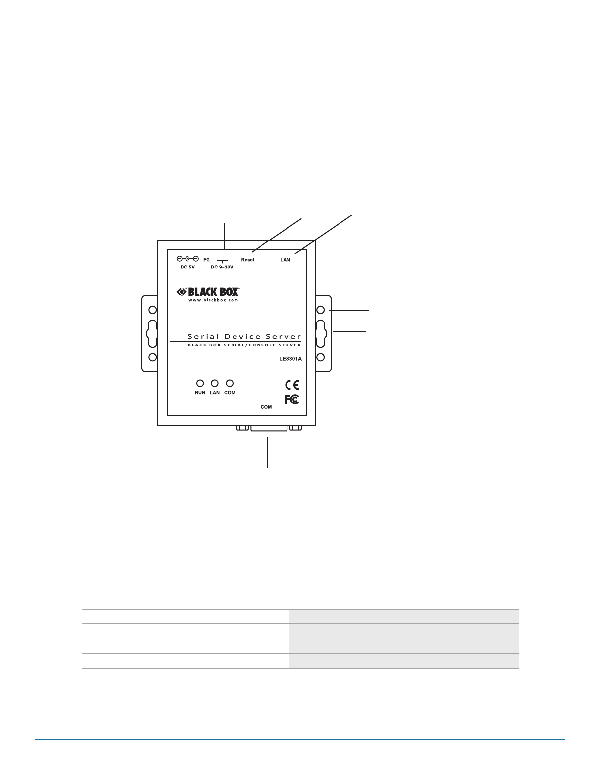
2.3 Hardware Description
Figures 2-1 through 2-3 show the Ethernet Serial Server’s back panel, top panel, and front panel views. Table 2-1 describes its
components.
3-pin male terminal
block for power input
RJ-45 10 - /100 -Mbps
Ethernet port
LES301A user manual
Reset
button
Figure 2-1. Back panel.
724-746-5500 | blackbox.com
Page 11
Page 12

724-746-5500 | blackbox.com
Chapter 2: Overview
DC 9–30 V
DB9 male serial port
Reset
button
Figure 2-2. Top panel.
RJ-45
10- /100-Mbps
port
DIN rail screw hole
Wallmount screw hole
DB9 male serial port
Figure 2-3. Front panel.
Table 2-1. Ethernet Serial Server components.
Message Description
LED off Ethernet is disconnected
LED is blinking green Data is transmitted at 100 Mbps on Ethernet
LED is blinking orange Data is transmitted at 10 Mbps on Ethernet
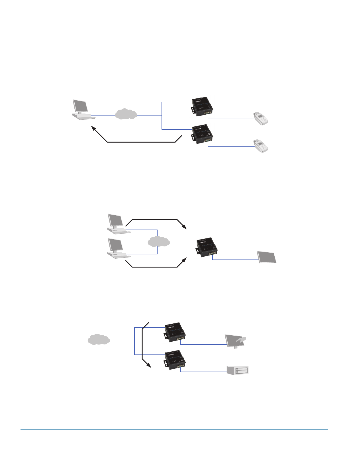
2.4 Application Connectivity
TCP Server Mode: LES301A can be configured as a TCP server on a TCP/IP Network to wait for other applications (clients) in the
host computer to establish a connection with the serial device. After the connection is established between the serial device and
the host computer, data can be transmitted in both directions.
Computer
LES301A
Figure 2-4. TCP server mode.
Serial bus
PLC
Page 12
724-746-5500 | blackbox.com
LES301A user manual
Page 13
Chapter 2: Overview
TCP Client Mode: LES301A can be configured as a TCP client on TCP/IP network to establish a connection with other
applications (server) in the host computer actively. After the connection is established, data can be transmitted between the serial
device and the host computer in both directions.
Remote control
host
LES301A
Card
reader
LES301A
Figure 2-5. TCP Client mode.
UDP Mode: UDP is a faster but non-guaranteed datagram delivery protocol. LES301A can be configured as a UDP mode on TCP/
IP Network to establish a connection using unicast or multicast data from the serial device to one or multiple host computers. The
opposite is also true.
Computers
Ethernet
Figure 2-6. UDP mode.
Tunneling Mode: In this mode, a serial connection with two or more LES301A units established sends data over TCP/IP
Network. This extends the 50-foot (15-m) RS-232 distance limit.
LES301A
LES301A
Serial bus
Card
reader
Display
LES301A user manual
Ethernet
Touchscreen
Serial bus
LES301A
Figure 2-7. Tunneling mode.
724-746-5500 | blackbox.com
PLC
Page 13
Page 14
724-746-5500 | blackbox.com
Chapter 3: Hardware Setup
3. Hardware Setup
NOTE: Figures 2-1 through 2-3 in Chapter 2 show the LES301A unit’s back, top, and front views.
NOTE: To reset the settings to the default value, press the LES301A‘s reset button.
Figure 3-1 shows the interfaces.
DC 9–30 V
Reset
button
RJ-45
10/100 Mbps
port
DIN rail screw hole
Wallmount screw hole
3.1 LED Indicators
3.1.1 LAN LED
Message Description
LED off Ethernet is disconnected
LED is blinking green Data is transmitted at 100 Mbps on Ethernet
LED is blinking orange Data is transmitted at 10 Mbps on Ethernet
Page 14
DB9 male serial port
Figure 3-1. LES301A interfaces.
Table 3-1. LAN LED message.
724-746-5500 | blackbox.com
LES301A user manual
Page 15

3.1.2 COM Port LED
Table 3-2. COM port LED message.
Message Description
Off No data is transmitted on the COM port
LED is blinking Data is transmitted on the COM por t
3.1.3 RUN LED
Table 3-3. RUN LED message.
Message Description
On Jumper JP1 Pin 1 and Pin 2 are shorted to disable AP firmware running
LED is blinking every 0.5 second AP firmware is running normally
3.2 Installation Procedures (LES301A-KIT or LES301AE-KIT)
Chapter 3: Hardware Setup
Step 1: Connect an LES301A to the included power supply (PS012 or PS012E) or to a 9–30 VDC source.
Step 2: Connect the LES301A to an Ethernet network. Use a standard straight-through Ethernet cable to connect to a hub/
switch, or connect it to a PC’s Ethernet port via a cross-over Ethernet cable.
NOTE: The PC must be in the same subnetwork as the LES301A.
Step 3: Connect the LES301A’s serial port to a serial device.
NOTE: You may need an adapter (LES30X-TB5) for RS-485 or RS-422 applications.
Step 4: Mount the LES301A to a wall or panel using the included mounting screws. Or, mount the unit to a DIN rail rack using
the DIN Rail Kit (LES30X-DR).
NOTES: Disconnect the device from power source completely before installing and wiring the server.
Do not exceed the maximum allowable current of the power cord and common wire. If you don’t, the wire might overheat
and cause serious damage to the connected and neighboring equipment.
The casing will be too hot to touch when operating in harsh environments. Please handle with care.
NOTE: Ground the LES301A properly through frame ground.
LES301A user manual
724-746-5500 | blackbox.com
Page 15
Page 16
724-746-5500 | blackbox.com
Chapter 4: Software Setup
4. Software Setup
The LES301A Ethernet Serial Server is shipped with default settings shown in Table 4-1.
Table 4-1. Default software settings.
Property Default value
IP address 10.0.50.100
Gateway 10.0.0.254
Subnet mask 255.255.0.0
User name admin
Password Null (leave it blank)
COM 1 9600, None, 8, 1, No flow control, buffer disabled, packet delimiter timer 2 ms
Link 1 Type: TCP server, listen port 4660, filter=0.0.0.0, virtual COM disabled
SysName of SNMP name
SysLocation of SNMP location
SysContact of SNMP contact
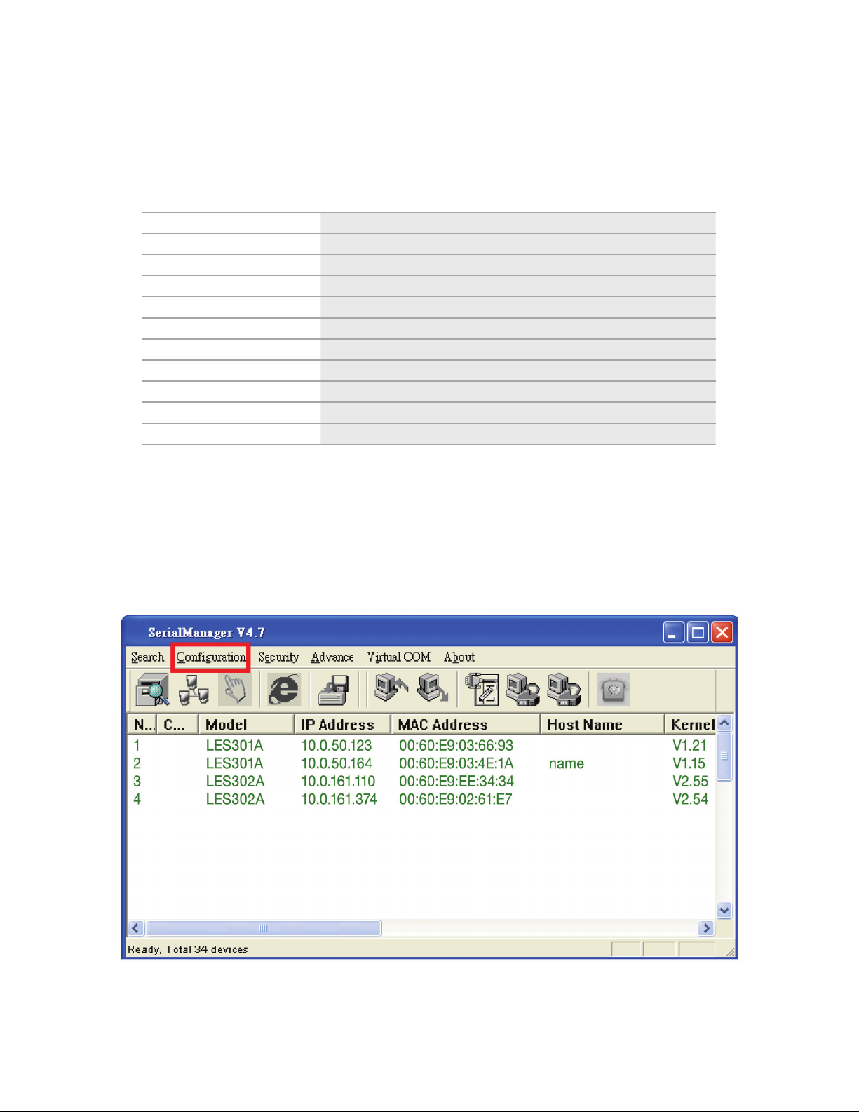
4.1 Configuration by SerialManager
4.1.1 Static IP
Use SerialManager that’s included on the product CD to configure the LES301A’s network parameters. Click on the
“Configuration” button (see Figure 4-1) then give it static IP information (see Figure 4-2.)
Page 16
Figure 4-1. Configure using SerialManager.
724-746-5500 | blackbox.com
LES301A user manual
Page 17
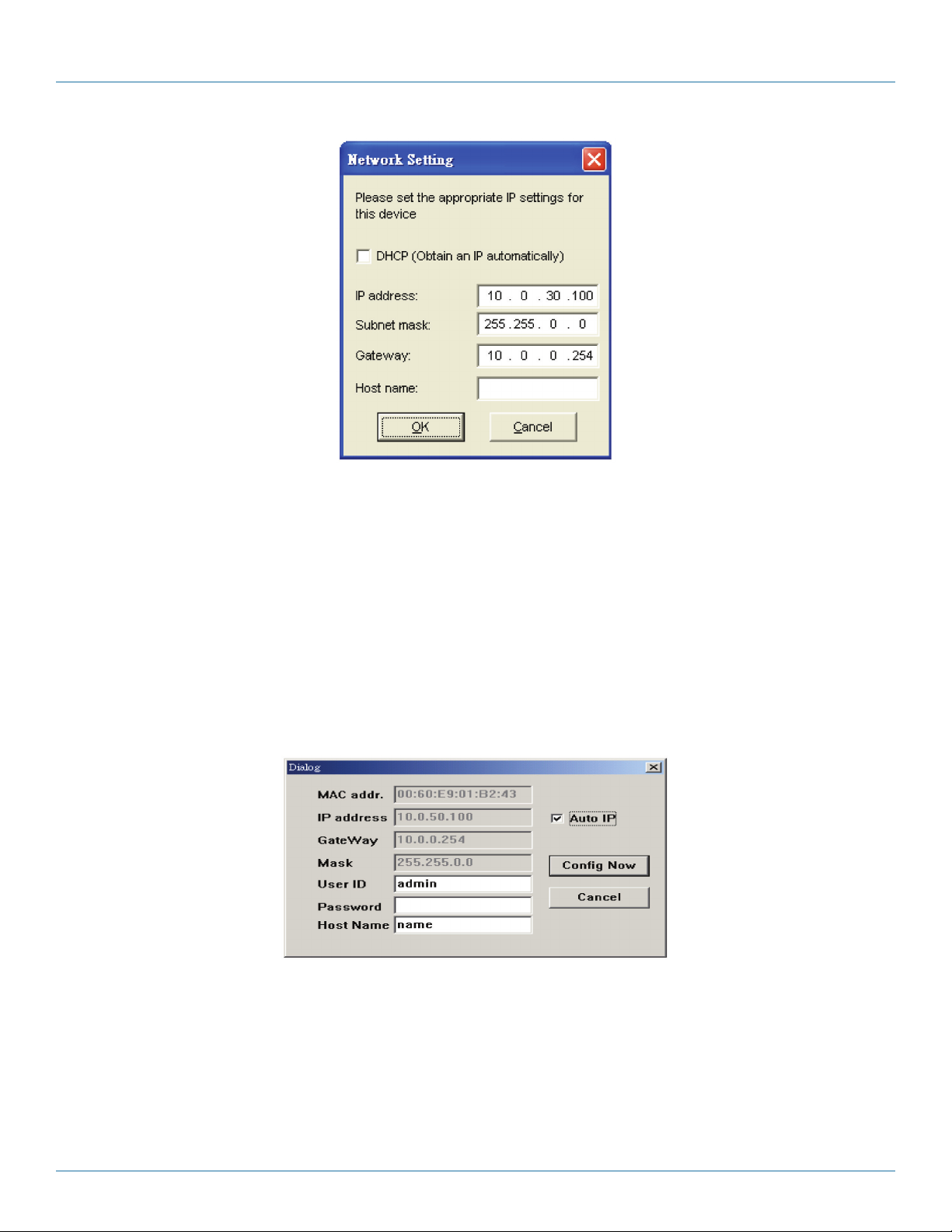
Figure 4-2. Static IP setup dialog window.
Chapter 4: Software Setup
4.1.2 Auto IP (Dynamic IP)
A DHCP server can automatically assign the IP address and network settings. The LES301A supports the DHCP function. By
default, the DHCP function on the LES301A is disabled; you can use SerialManager software to search network information automatically by following these steps:
1. Execute SerialManager (Figure 4-1).
2. Click on the IP address of the LES301A in SerialManager.
3. Click on the “Config” button, and the dialog window will pop up (Figure 4-2).
4. Check ”DHCP (Obtain an IP automatically)” (Figure 4-3).
5. Click on the “Config Now” button (The LES301A will restart and get its IP from the DHCP server automatically.)
LES301A user manual
Figure 4-3. SerialManager auto IP dialog window.
724-746-5500 | blackbox.com
Page 17
Page 18
724-746-5500 | blackbox.com
Chapter 4: Software Setup
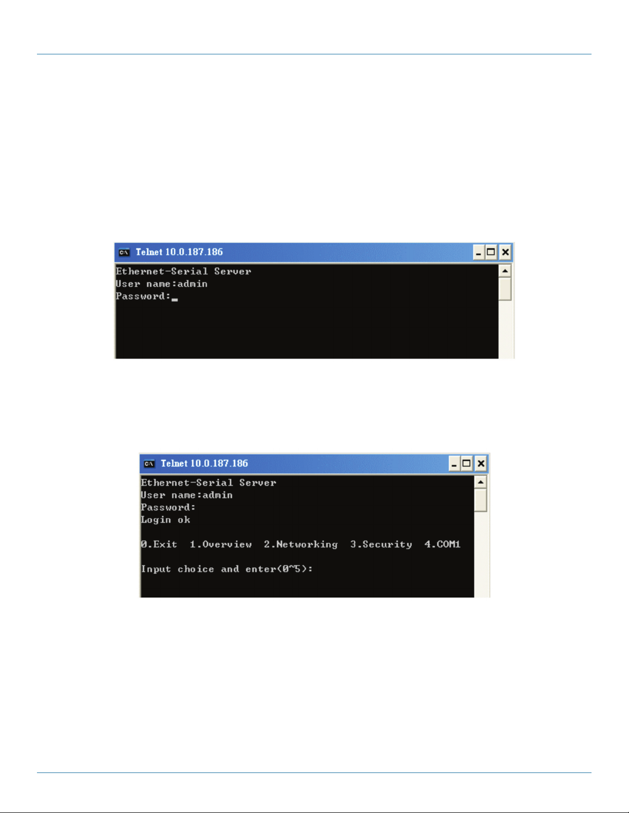
4.2 Configuration by Telnet Utility
You can use the Telnet utility to change configuration settings of the LES301A.
4.2.1 Log into the System
Open the MS-DOS® command prompt window.
Telnet to the LES301A using the command “Telnet IP_address.” (For example: Input Telnet 10.0.50.100 in the MS-DOS
command prompt window). After you Telnet to LES301A, the system prompts for a password; the default password is blank.
(Figure 4-4).
Figure 4-4. Log into the system.
NOTE: Press the LES301A default button to reset the password to the default value.
After verifying the password, the following terminal screen appears (see Figure 4-5).
Figure 4-5. Main menu.
NOTES: If the LES301A does not receive any command within one minute, Telnet will be terminated automatically.
The networking parameter changes will take effect only when you exit and restart the LES301A.
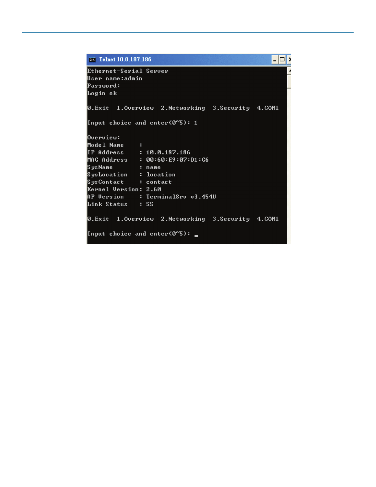
Select “1” from “Input choice and enter (0–4):” to enter the overview page as shown in Figure 4-6.
Page 18
724-746-5500 | blackbox.com
LES301A user manual
Page 19
Chapter 4: Software Setup
Figure 4-6. Overview.
This page gives you general information about the LES301A, including IP and MAC address, SNMP information, kernel and AP
information, and connection status of the device.
LES301A user manual
724-746-5500 | blackbox.com
Page 19
Page 20
724-746-5500 | blackbox.com
Chapter 4: Software Setup
4.2.2 Networking
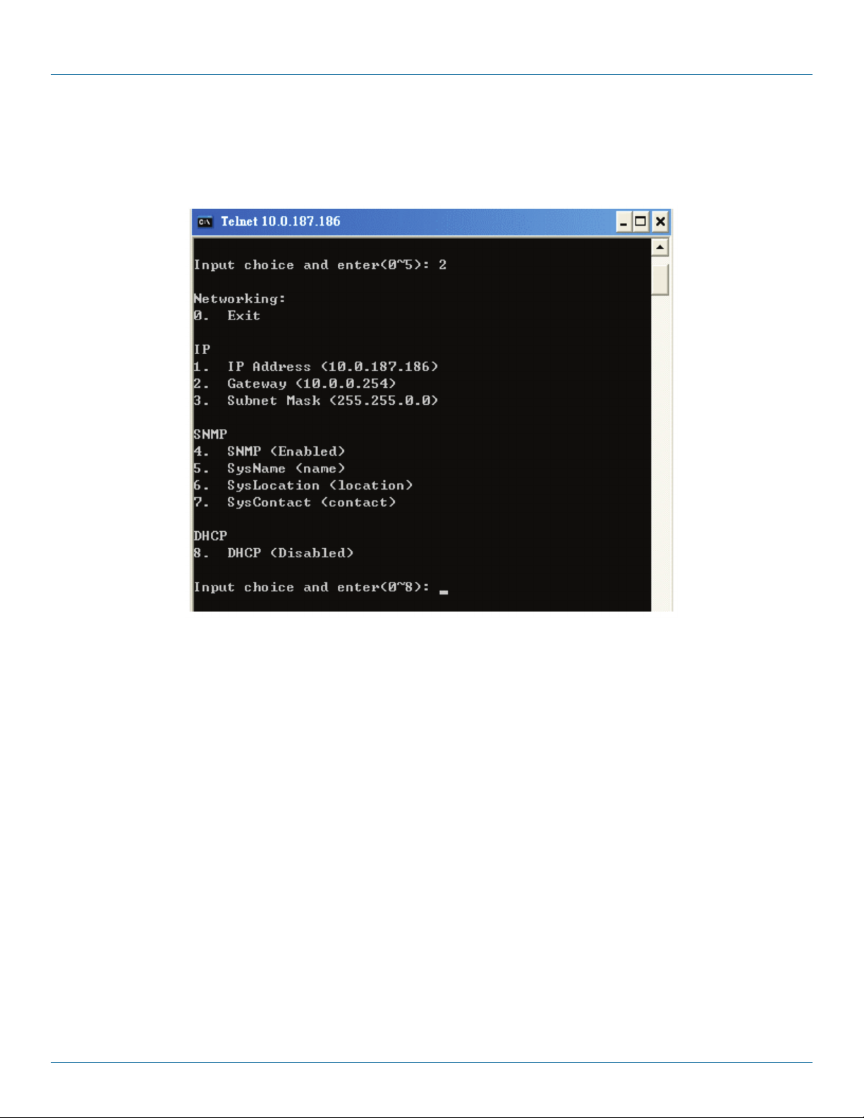
Select “2” from “Input choice and enter (0–4):” to enter the Networking page (see Figure 4-7).
Figure 4-7. Network settings.
This page allows you to change the LES301A’s network settings, including IP address, subnet mask, gateway IP address, and
SNMP information.
NOTE: Any setting change made on this page won’t take effect until you restart the device.
NOTE: Press the “ESC” key to return to the previous menu.
Page 20
724-746-5500 | blackbox.com
LES301A user manual
Page 21
Chapter 4: Software Setup
4.2.3 Change the Password
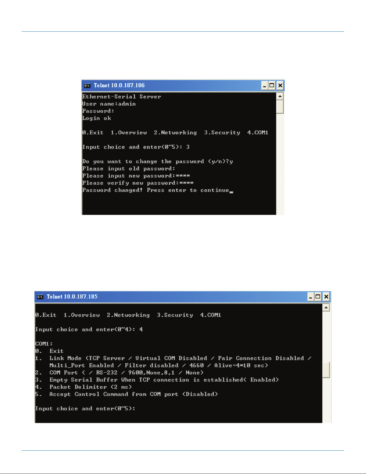
1. Select “3” from “Input choice and enter (0–4):” and the following screen appears (see Figure 4-8).
Figure 4-8. Change the password.
2. To change the password, type the old password in the “Please input old password” field, then type the new password in the
“Please input new password” and the “Please verify new password” fields.
NOTE: Press the product’s default key to reset the password to the default value.
4.2.4 COM1 Setup
Select “4” from “Input choice and enter (0–4):” The following screen appears (see Figure 4-9).
LES301A user manual
Figure 4-9. COM1 setup.
724-746-5500 | blackbox.com
Page 21
Page 22

724-746-5500 | blackbox.com
Chapter 4: Software Setup
The page enables you to configure COM1 parameter settings, including COM working mode, port parameters, enabling or
disabling serial buffer’s data, and setting packet delimiter.
Figure 4-10. COM port selection screen.
LINK Mode Setup: Configure LES301A as a TCP server (see Figure 4-10).
1. Type “1” when prompted “Input choice and enter (1–4):” of COM1.
2. Type “1” when prompted “Input choice (1–5) and enter: ”
3. Input the local port in the “Please input local port: ” prompt.
To enable the IP filter:
1. Type “y” at the “Do you want to enable the IP filter (y/n)?” prompt.
2. Input the source IP in the “Please input Filter_IP: ”
3. Double-click the “Enter” key.
To disable the IP filter:
1. Type “n” at the “Do you want to enable the IP filter (y/n)?” prompt.
2. Double-click the “Enter” key.
3. Input idle time in “Please input idle time to send TCP alive packet(4*10sec):” prompt. (If you input 2, the sending TCP keep
alive packet period will change to 2*10 sec.)
NOTES:
1. The IP filtering function is disabled if setting FILTER_IP to “0.0.0.0”.
2. The IP filter is disabled by default.
3. If the IP filter is enabled, only the assigned source IP can connect to the LES301A.
724-746-5500 | blackbox.com
Page 22
LES301A user manual
Page 23

Chapter 4: Software Setup
Figure 4-11. Link Mode—TCP server setup.
4.2.5 Configure the LES301A as a TCP Client
1. Type “2” at the “Input choice (1–5) and enter:“ prompt (see Figure 4-11)
2. Input the destination IP in the “Please input Destination IP:” prompt.
3. Input the destination port in the “Please input Destination port:” prompt.
Type “1” for Connected always:
1. Double-click the “Enter” key.
2. Input idle time at the “Please input idle time to send TCP alive packet(4*10sec):” prompt. (If you input “2”, the sending TCP
keep alive packet period will change to 2*10 sec)
Type “2” for Trigger by receiving COM port data:
1. Input the idle time to disconnect at the “Please input idle time to disconnect (0 sec , 1–255):” prompt. (If you input “0” disable
the function; if you input “2”, the serial Inactivity beyond 2 sec will cause the unit to disconnect.)
2. Input the error retrying time in the “Please input waiting time for error retrying (0 minute, 1–255):” prompt. (If you input “0”,
the function is disabled; if you input “2”, the serial Inactivity beyond 2 sec will cause the unit to disconnect.)
3. Double-click the “Enter” key.
4. Input the idle time at the “Please input idle time to send TCP alive packet(4*10sec)” prompt. (If you input “2,” the sending TCP
keep alive packet period will change to 2*10 sec.)
LES301A user manual
724-746-5500 | blackbox.com
Page 23
Page 24

724-746-5500 | blackbox.com
Chapter 4: Software Setup
Figure 4-12. Link mode TCP client setup.
4.2.6 Configure the LES301A as a UDP Client
For example, the local port is 4660, the destination IP is 10.0.29.254, and the destination port is 666 (see Figure 4-13).
Figure 4-13. Link Mode-UDP client setup.
Page 24
724-746-5500 | blackbox.com
LES301A user manual
Page 25

Chapter 4: Software Setup
4.2.7 COM Port Setting
Type “2” at the “Input choice and enter (1–4):” prompt for COM1. The following screen will appear. You can then give the COM
port an alias name, set the baud rate and parity, determine the number of data bits and stop bits, and decide if you want to use
flow control (and also the type of flow control you want to use). See Figure 4-14.
Figure 4-14. COM port setting.
4.2.8 Enabling the Serial Data Buffer
Type “3” at the “Input choice and enter (1–4):” prompt. By default, the COM port serial data buffer is enabled, meaning that
when TCP/IP Ethernet connection is broken, serial data collected from serial device will be empty in LES301A. Once the TCP/IP
connection is resumed, the serial data will be sent through Ethernet connection. You can enable or disable this. (See Figure 4-15.)
Figure 4-15. COM port—Enable or disable serial data buffer.
LES301A user manual
724-746-5500 | blackbox.com
Page 25
Page 26

724-746-5500 | blackbox.com
Chapter 4: Software Setup
4.2.9 Setting Packet Delimiter
Packet delimiter is a way of controlling packets within serial communication. It can prevent packets from being cut, thus keeping
the packets complete. The LES301A provides two ways to set the parameters: inter-character timer and terminator. By default, the
packet delimiter timer is 1 ms. You can change the timer shown in Figure 4-16.
Figure 4-16. Setting packet delimiter timer.
You can also choose the character pattern as the packet delimiter as shown in Figure 4-17.
Figure 4-17. Setting the packet delimiter-character pattern.
4.2.10 Accept Control Command from COM Port
The LES301A can also accept serial control commands directly over the network following RFC2217 format. For more details
about this function, contact Black Box Tech Support at 724-746-5500 or info@blackbox.com.
4.3 Configuration Using Web Browser
1. Make sure your PC is located on the same network subnet as the LES301A.
2. Open a Web browser, then type in the LES301A IP address to configure. The default user name is “admin” and the default
password is null (leave it blank).
3. The LES301A’s network, link mode, and COM ports settings can be configured in different Web pages.
4. Click “Save Configuration” to save the settings.
Page 26
724-746-5500 | blackbox.com
LES301A user manual
Page 27

Chapter 4: Software Setup
5. Click on the ”Restart” button to activate the change.
You can also modify various settings through the Web server interface. To do so, follow the steps below.
4.3.1 Log in to the System
1. From the Web browser, type the LES301A’s IP address in the URL.
Example: http://10.0.50.100
2. The following authentication screen appears. (See Figure 4-18.) Type in the user name and password, then click on “OK.” The
user name is admin, and password is left blank by default.
Figure 4-18. Log into the system via Web.
3. The following overview page appears. (See Figure 4-19.)
LES301A user manual
724-746-5500 | blackbox.com
Page 27
Page 28

724-746-5500 | blackbox.com
Chapter 4: Software Setup
Figure 4-19. Overview.
4.3.2 Change the Password and RS-232/RS-485/RS-422 Type Selection
1. Click on the “Security” link and the screen shown in Figure 4-20 appears.
Figure 4-20. Change the password.
Page 28
724-746-5500 | blackbox.com
LES301A user manual
Page 29

Chapter 4: Software Setup
2. Type in the old password in the “Old Password” field, type in the new password in the “New Password” and the “Verified
Password” fields, and then click on “Save Configuration” to update the password.
NOTE: Press the default key to reset password to the default value.
3. COM type selection: Click on “COM1” Link and the following screen appears (see Figure 4-21). Select the COM type and click
on “Save” to update the COM port typesetting.
DOES THIS SCREEN EXIST FOR LES301A??
Figure 4-21. COM type selection.
4.3.3 Network Setup
Click on the “Networking” link and the following screen appears. Fill in the IP information under the TCP/IP field. Or, you can
configure the unit by clicking on DHCP to obtain auto IP address, gateway, and subnet mask information.
Enable SNMP by checking “Enable,” then fill in network identification information under SNMP field and click on the “Save
Configuration” button to save the changes.
NOTE: The setting will not become effective until you restart the LES301A.
LES301A user manual
724-746-5500 | blackbox.com
Page 29
Page 30

724-746-5500 | blackbox.com
Chapter 4: Software Setup
Page 30
Figure 4-22. Network setup.
724-746-5500 | blackbox.com
LES301A user manual
Page 31

Chapter 4: Software Setup
4.3.4 Configure the LES301A as a TCP Server
You can configure the LES301A with transparent mode as the default.
1. Click on the “COM1” link.
2. Configure the LES301A as a TCP server.
3. Input the local listening port “4660.”
To enable the IP filter:
1. Check “IP filter.”
2. Input the source IP in the “Source IP“ field.
If you don’t want to enable the IP filter:
1. Don’t check “IP filter.”
2. Input the idle time at the “Please input idle time to send TCP alive packet(sec):” prompt. (If you input “2,” the sending TCP
keep alive packet period will be changed to 2*10 sec.)
3. Input the TCP Inactivity time at the “TCP Inactivity Time Before Disconnect( sec):” prompt. (If you input “2,” TCP Inactivity
beyond 2 sec will cause a disconnect.)
4. Click on the “Save Configuration” button to save the changes.
NOTE:
1. The IP filtering function is disabled if you set the FILTER_IP to “0.0.0.0”.
2. The IP filter is disabled by default.
3. If the IP filter is enabled, only the source IP assigned can connect to the LES301A.
LES301A user manual
Figure 4-23. LINK1 setup—TCP server.
724-746-5500 | blackbox.com
Page 31
Page 32

724-746-5500 | blackbox.com
Chapter 4: Software Setup
\
Figure 4-24. COM1 setup—TCP server.
NOTES:
1. The default port number for the LES301A is 4660 and it is associated with serial port COM1 respectively. After your application
program connects to the TCP port 4660 of the LES301A, data sent to this TCP connection from your application program is
transparent to the LES301A’s COM1. The opposite is also true.
2. The serial interface will show a different port interface according to the model of the serial server.
4.3.5 Configure the LE301A As a TCP Client
Configure the LES301A as a TCP client, for example, the destination IP is 10.0.29.11, and the destination port is 4660.
1. Input destination IP “10.0.29.11”
2. Input destination port “4660”
3. Input idle time at the “Please input idle time to send TCP alive packet( sec):” prompt. (If you input 4, the sending TCP
keep-alive packet period will change to 4*10 sec.)
4. Select “TCP Connect On Power-on” to keep trying to establish a TCP connection after Power on.
5. Select “TCP Connect On Any Serial Character,” and any serial character will trigger to establish the TCP connection.
6. Input idle time to disconnect at the “Serial Inactivity Time before disconnect (0sec , 1–255):” prompt. Input “0” to disable the
function; input ”2” and the serial Inactivity beyond 2 sec will cause a disconnect.
Page 32
724-746-5500 | blackbox.com
LES301A user manual
Page 33

Chapter 4: Software Setup
7. Input the error retrying time at the “Waiting Time Between Re-connect Attempts (0 minute, 1–255):” prompt. Input “0” to
disable the function; input “2” and the serial Inactivity beyond 2 sec will cause a disconnect.
8. Click on the “Save Configuration” button to save the changes.
Figure 4-25. COM1 setup—TCP client
4.3.6 Pair Connection
If the serial connection is established with two or more LES301A units to send data over Ethernet network, that is, pair
connection mode, you can choose “pair connection,” which is indicated in the following figure for any type of serial device.
LES301A user manual
724-746-5500 | blackbox.com
Page 33
Page 34

724-746-5500 | blackbox.com
Chapter 4: Software Setup
Figure 4-26. COM1 setup—pair connection.
Configure the LES301A as UDP mode. The local port is 4660, the destination IP is 10.0.29.254, and the destination port is 4660.
Page 34
724-746-5500 | blackbox.com
LES301A user manual
Page 35

Chapter 4: Software Setup
Figure 4-27. COM1 setup—UDP mode.
1. Click on “Save Configuration” to save the changes.
2. If the update is successful, the following screen appears.
Figure 4-28. Configuration is successful.
4.4 Assign a New IP Address by ARP Command
Use ARP command to assign a static IP address to LES301A using its hardware MAC address. The MAC address is printed on the
rear side of device in the format of “0060E9-xxxxxx.” The following example shows how it works in the MS-DOS command
prompt window.
For example, change IP from 10.0.50.100 to 10.0.50.101, and the MAC address for LES301A is 00-60-e9-11-11-01.
Step 1: Add the new host IP to ARP table.
• Open the MS-DOS command prompt window.
• Input “arp -s 10.0.50.101 00-60-E9-11-11-01.”
LES301A user manual
724-746-5500 | blackbox.com
Page 35
Page 36

724-746-5500 | blackbox.com
Chapter 4: Software Setup
Figure 4-29. MS-DOS command prompt window.
Step 2: Change to new IP via Telnet Port 1.
• Input “telnet 10.0.50.101 1”
NOTE: The Telnet will fail, and the LES301A will restart automatically. After restart, the IP address should change to 10.0.50.101.
Step 3: Use a new IP to configure LES301A via Telnet.
• Input “telnet 10.0.50.101”
NOTE: When using this method to change the IP address, the PC's IP address and the LES301A’s IP address must belong to the
same subnet.
NOTE: The changed IP address must be legal, otherwise it will be changed back to the default value (10.0.50.100) after restart.
Page 36
Figure 4-30. Assigning a new IP address by ARP command.
724-746-5500 | blackbox.com
LES301A user manual
Page 37

Chapter 5: Using Virtual COM
5. Using Virtual COM
Virtual COM driver mode for windows converts COM data to LAN data to control the RS-232 port on an LES301A via the LAN.
By creating virtual COM ports on the PC, the Virtual COM driver redirects the communications from the virtual COM ports to an
IP address and port number on an LES301A that connects the serial line device to the network. Figure 5-1 shows the Virtual COM
connection diagram.
Hub
PC
Physical COM1
Physical COM2
COM3 (Virtual COM port)
COM4 (Virtual COM port)
COM5 (Virtual COM port)
COM6 (Virtual COM port)
OS Driver Level:
COM 256 (Virtual COM port)
Serial Line
Serial Device 1
Serial Line
TCP/IP
network
LES301A
Figure 5-1. Virtual COM connection diagram.
5.1 Setup of a Virtual COM Driver
5.1.1 Pre-installation Requirements
The PC’s operating system should comply with the following requirements:
• Processor: Intel® compatible, Pentium® class
Serial Device 2
Serial Line
Serial Device 3
Serial Line
Serial Device 4
units
• Operating system: Windows® Server 2003, Windows XP, Windows 2000®, Windows NT 4.0 SP5 or later, Windows Me,
Windows 98, Windows 95, Microsoft® NT/2000 Terminal Server, Citrix MetaFrame
5.1.2 Supported Firmware
The Virtual COM driver supports firmware AP v3.0 and later of LES301A device servers.
LES301A user manual
724-746-5500 | blackbox.com
Page 37
Page 38

724-746-5500 | blackbox.com
Chapter 5: Using Virtual COM
5.1.3 Limitation
The Virtual COM driver enables you to select up to 256 COM ports as Virtual COM ports in a SerialManagerPC. You can select
from a list of COM ports from COM1 to COM256.
5.1.4 Installation
Turn off all anti-virus software before beginning the installation. Run the Virtual COM setup file included in the CD to install
Virtual COM driver for your operating system.
Select one or two COM ports to become the Virtual COM ports.
5.1.5 Uninstalling
1. From the Windows Start menu, select “Setting,” “Control Panel,” “Add/Remove Programs.”
2. Select “Serial IP”in the list of installed software.
3. Click on the “Add/Remove” button to remove the program; or, from the Windows Start menu, select “Programs,” “Serial IP,”
“Uninstall Serial IP.”
5.2 Virtual COM Communication
5.2.1 Enable Virtual COM on LES301A
From a Web browser, access the LES301A by typing its IP address, then click on the COM1 link to access the COM1 page. On the
top half of the page, click on “TCP Server” and enable Virtual COM by putting a check in front of the “Enable” button, then type
in the local port number in the “Local Port” field.
Figure 5-2. Enable VirtualCOM.
Or, you can enable Virtual COM through Telnet configuration by setting COM1 as TCP server (Figure 9-2), and type in the local
port number for COM1, then enable Virtual COM as shown in Figure 5-3.
Page 38
724-746-5500 | blackbox.com
LES301A user manual
Page 39

Chapter 5: Using Virtual COM
Figure 5-3. Enable Virtual COM via Telnet.
5.2.2 Run Serial/IP on PC
In the Window Start Menu, go to “Programs,” select “Serial/ IP” and select “Control Panel.” When the“Select Port” window
pops up, select the serial port you want to configure. The configuration window will appear (see Figure 5-4).
LES301A user manual
724-746-5500 | blackbox.com
Page 39
Page 40

724-746-5500 | blackbox.com
Chapter 5: Using Virtual COM
Figure 5-4. Serial/IP configuration.
On the right side of Figure 5-4 is a sample Virtual COM Control Panel window. On the left side is the list of the COM ports that
you have selected (in the Select Ports window) for use by the Virtual COMRedirector. If you want to change which ports appear
in this list, use the “Select Ports” button.
Each COM port has its own settings. When you click on a COM port, the Control Panel display changes to reflect the settings for
that COM port.
NOTE: When you change settings for a COM port, the changes are effective immediately. There is no separate confirmation
dialog to confirm or cancel your changes.
5.3 Configuring Virtual COM Ports
Configure each Serial/IP COM port as follows:
1. Select a COM port in the list.
2. For IP Address of Server, enter a numeric IP address for the serial server.
3. For Port Number, enter the TCP port number that the serial server uses to provide its serial ports to the network.
4. For Server Credentials, the default is “No Login Required.” If your serial server does require a login by the Virtual
COMRedirector, the Virtual COMRedirector needs to provide a username and/or password every time an application tries to
use the serial server.
Page 40
724-746-5500 | blackbox.com
LES301A user manual
Page 41

Chapter 5: Using Virtual COM
5. Click the “Configuration Wizard” button and then click the “Start” button that appears in the wizard window. This important
step verifies that the Virtual COMRedirector can communicate with the serial server using the settings you have provided. If the
Log display does not show errors, click the “Use Settings” button in the wizard. This makes the recommended settings effec-
tive and returns you to the Control Panel to continue with the following steps.
Figure 5-5. Configuration Wizard.
6. For Connection Protocol, the setting must match the TCP/IP protocol that the serial server supports. The Configuration Wizard
is usually able to determine the correct setting.
7. For COM Port Options, the settings must match the COM port behavior expected by the PC application that will use this COM
port. The Configuration Wizard will recommend a combination of settings.
LES301A user manual
724-746-5500 | blackbox.com
Page 41
Page 42

724-746-5500 | blackbox.com
Chapter 6: SNMP Setup
6. SNMP Setup
6.1 SNMP Network Management Platform
LES301A is an SNMP device that allows many popular SNMP network management platforms such as HP® OpenView® and
SunNet Manager to conduct SerialManager.
Depending on the network management tools you are using, you can collect device LES301A information from running the
management tools including IP address, DNS name, system descriptions, and NIC information, etc.
6.2 Using NetworkView as an Example
NetworkView is a compact network management tool from NetworkView Software, Inc. (www.networkview.com). It discovers all
TCP/IP nodes in a network using DNS, SNMP, and ports information and documents with their printed maps and reports for
future use.
First, download and install the tool on your PC (Windows 2000 and Windows XP), then start NetworkView.
1. Click on the button to open a new file. The following screen will appear. In the Addresses field, enter the IP address range to
search.
Figure 6-1. IP address searching.
2. Click on “OK” and the following dialog box will display the searching progress.
Figure 6-2. Searching progress.
3. After the search is completed, NetworkView will display the devices found in the main window.
724-746-5500 | blackbox.com
Page 42
LES301A user manual
Page 43

Chapter 6: SNMP Setup
Figure 6-3. NetworkView displays the devices found.
4. Double-click on the device icon to display information about the device, including IP Address, Company, SysLocation (Max 15
characters), SysName (Max 9 characters), and types, etc.
Figure 6-4. NetworkView display device information.
NOTES:
1. The NetworkView tool is limited to information extracting and viewing only.
2. To modify the configurations, use the Web server, Telnet, or SerialManager configuration utilities.
LES301A user manual
724-746-5500 | blackbox.com
Page 43
Page 44

724-746-5500 | blackbox.com
Chapter 7: Start Writing Your Own Applications
7. Start Writing Your Own Applications
Before you start writing host applications or programs to interact with LES301A, make sure you have done the following.
7.1 Preparing the System
1. Properly connect the LES301A hardware, including power, Ethernet, and serial cable.
2. Properly configure the LES301A parameters, including connection type, IP address, gateway IP address, and network mask (see
Chapter 3).
3. Configure the LES301A as a TCP Server using the default TCP port number “4660.”
4. The host (PC) application program must be configured as a TCP client and connects to the LES301A with a designated TCP port
number “4660” for COM1.
5. Make sure the LES301A is running by checking the running status through the SerialManager configuration utility.
7.2 Running the Sample Program
Sample programs written in VB and VC++ are included in the package for reference; source codes are also included. You can find
test programs on the product CD or diskette under the directory of \sample\vb_ap\and \sample\vc_ap, respectively.
There are two test programs: TCPTEST written in Visual Basic and TCPTEST2 written in Visual C++.
7.2.1 TCPTEST in Visual Basic
This sample program is written in Visual Basic 5.0 with Winsock Controls. It shows how to send and receive data between host
(PC) and LES301A via Ethernet in two socket ports.
Run Visual Basic and open sample program tcptest.vbp. After the program is started successfully, you can start testing functions.
For more information, press “Help” in the program for a detailed explanation.
NOTE: Make sure the Microsoft visual studio family software is installed on the computer. Otherwise, the sample program will not
run.
Page 44
Figure 7-1. TCP test sample program in Visual Basic.
724-746-5500 | blackbox.com
LES301A user manual
Page 45

Chapter 7: Start Writing Your Own Applications
7.2.2 TCPTEST2 in Visual C
To start the program, type in the following command in the command line prompt:
TCPTEST2 IP_Address Port_Number
Figure 7-2. TCP test sample program in Visual C
The command “tcptest2 10.0.50.100 4660” connects to a TCP server that has IP address “10.0.50.100” and port number
“4660.” The received data is displayed on the screen and the data typed in is sent to the TCP server of the designated port
number. You can also send binary data in hex format with a leading character “\.” For example, “\00” and “\FF” represent ASCII
code 0 and 255, respectively.
You can also use a modem to connect to the serial server. Command "AT\Od" sends a standard AT command to the modem,
which in return responds with an "OK\0D\0A" message to the host application.
To exit the program, type “=” then press the Enter key.
LES301A user manual
724-746-5500 | blackbox.com
Page 45
Page 46

724-746-5500 | blackbox.com
Chapter 8: Diagnostics
8. Diagnostics
There are several ways that you can check on the status and availability of the LES301A.
8.1 Use the Standard TCP/IP Utility Ping Command
From Windows “Start” menu, select “Run” and type in “ping <TCP Server IP address>.”
If the connection is established, the Reply messages are displayed; otherwise it will indicate that the request timed out.
Figure 8-1. Standard TCP/IP utility ping command.
8.2 Use the SerialManager Configuration Utility Program
Use the SerialManager configuration program that’s included on the product CD or diskette to check on the status of the
LES301A. You can read the status and version from the tool.
For example, “S” means that COM1 is the server mode and it is not connected.
Figure 8-2. SerialManager configuration Utility.
8.3 Use TCPTEST.exe or TCPTEST2.exe Sample Program
Use sample programs TCPTEST.exe and TCPTEST2.exe that are included on the product CD to check on the status of LES301A.
Refer to Section 7.2 to run the sample programs.
Page 46
724-746-5500 | blackbox.com
LES301A user manual
Page 47

Appendix A: Upgrade System Firmware
Appendix A: Upgrade System Firmware
After a new version of firmware is released, you can download it from www.blackbox.com. After you download the firmware,
follow the instructions listed below.
A.1 Upgrade Procedures
When you get a new software version, follow the sequences below to upgrade the LES301A.
1. To upgrade the firmware, connect a PC (Windows 95/98/NT/2000/XP) and the LES301A in the same TCP/IP network. Use a
ping command or the SerialManager program to verify their availability.
2. Prepare the download tool and press any key to edit its configuration file: “dapdl.cfg.” The dapdl.cfg file is on the CD you
received with your LES301A.
Figure A-1. Download screen.
3. Edit the "dapdl.cfg" file to fit your system’s needs. The content of the file looks like the following. Be sure to save the
modifications after you make the change.
Remote_IP10.0.50.100
LoadU5001ap.hex
The first line identifies the IP address of the LES301A, and the second line identifies the firmware (.Hex file) name to be down-
loaded.
4. Execute the utility program “download.bat” (it’s on the product CD).
5. Input the user name and password, and the new firmware will be downloaded.
Figure A-2. Input user name and password.
6. The LES301A will automatically restart each time the firmware is successfully downloaded.
LES301A user manual
724-746-5500 | blackbox.com
Page 47
Page 48

724-746-5500 | blackbox.com
Appendix A: Upgrade System Firmware
Figure A-3. Download finished screen.
A.2 Critical Issues of Upgrading
1. You can abort the upgrading process by pressing the “Esc” key on the host PC during the upgrading process. The LES301A will
restart automatically, and the system remains intact.
2. If the LES301A does not receive any upgrading data within 30 seconds, it will restart automatically and the system will remain
intact.
3. After the upgrading process finishes, the LES301A will program the flash memory, and the buzzer will beep 6 times, then
restart. Normally, it takes about 10 seconds to complete the programming process. If an error occurs during the programming
process, the LES301A will clear the corresponding memory, and the system remains intact.
A.3 Error Messages
A firmware upgrade may not be successful if errors occur during the process.
Table A-1. Firmware upgrade errors.
Error cause Message
Hex file text error
Illegal hex file format
LES301A handshaking problem
Configuration file
Hex file checksum error
Hex file format error
Hex File end- of-record error
LES301A ACK start address error
LES301A ACK length error
LES301A response command error
Remote IP not found
Open configuration file failure
Page 48
724-746-5500 | blackbox.com
LES301A user manual
Page 49

Appendix B: Disable System Firmware
Appendix B: Disable System Firmware
The application program (AP) LES301A firmware can be disabled. Do this if you downloaded a wrong version of firmware that
caused the system to crash.
To disable the current version of firmware and prevent it from executing, do the following:
1. Turn off the power, open the LES301A case.
2. Short Pin 1 and Pin 2 of Jumper JP1 on the right-top corner of the main board to disable AP firmware.
3. Power on the LES301A.
4. Download the correct AP firmware to LES301A.
5. Remove Pin 1 and Pin 2 of Jumper JP1 to enable AP firmware.
6. Close the case and continue operation.
LES301A user manual
724-746-5500 | blackbox.com
Page 49
Page 50

724-746-5500 | blackbox.com
Appendix C: Using SerialManager Utility
Appendix C: Using SerialManager Utility
C.1 SerialManager Utility Introduction
The SerialManager utility is a special tool for device management and configuration. Use it daily to manage various network
devices for address search, device positioning, parameter configuring, and firmware downloading.
C.2 Interface
The operating interface of the SerialManager utility is shown below:
Figure C-1. Operating interface of the SerialManager utility.
Table C-1. Cautions.
Caution field Description
! IP conflict. There are two devices with the same IP address in the network.
@ The device is using DHCP.
< The device is being located.
+ You have logged into the device.
? MAC conflict. There are two devices with the same MAC address in the net work.
C.3 Functions
C.3.1 Device Search
Use this function to search devices in the network. There are four methods to search devices: Search by Broadcast, Search by IP
addresses, Search by MAC addresses, and Re-scan devices using the current search method. To select the Search method, click on
“Search” in the main menu.
Page 50
724-746-5500 | blackbox.com
LES301A user manual
Page 51

Appendix C: Using SerialManager Utility
Figure C-2. Main menu.
Alternatively, you can select the search method by clicking the “Rescan button” on the toolbar.
Figure C-3. Rescan button.
Broadcast Search
Once “Broadcast Search” is selected, a box will pop up as in Figure C-4. You may type in or select a different broadcast address
based on the requirement.
LES301A user manual
724-746-5500 | blackbox.com
Page 51
Page 52

724-746-5500 | blackbox.com
Appendix C: Using SerialManager Utility
Figure C-4. Broadcast Search screen.
Search by IP Address
Once “Search by IP Address” is selected, an interface will pop up. Here, you have two options: “Select an IP address to search” or
“Search device in the range of IP address.”
Figure C-5. Search Devices by IP Addresses screen.
Search by MAC Address
If “Search by MAC Address” is selected, another box will pop up. Here, you can search in two ways: “Search a MAC address to
search” or “Search devices in the range of MAC address.”
Page 52
724-746-5500 | blackbox.com
LES301A user manual
Page 53

Appendix C: Using SerialManager Utility
Figure C-6. Search Devices by MAC Addresses screen.
Rescan
Once you click the “Rescan” button on the toolbar, the SerialManager utility will re-search devices by using the current search way.
C.3.2 Firmware
This function is applied to downloading a firmware into the selected device. You can enter the window for downloading by first
clicking a designated network device, and then selecting the submenu option “Firmware Download” in the main menu option
“Firmware”, or by directly clicking the “Upgrade” button from the disk.
LES301A user manual
Figure C-7. Download firmware.
724-746-5500 | blackbox.com
Page 53
Page 54

724-746-5500 | blackbox.com
Appendix C: Using SerialManager Utility
Figure C-8. SerialManager screen.
You can select and download the required firmware from the disk. You can also select several same devices at one time, and
update the firmware by selecting “Apply for all selected devices.”
Page 54
Figure C-9. Download firmware from disk.
724-746-5500 | blackbox.com
LES301A user manual
Page 55

Appendix C: Using SerialManager Utility
C.3.3 Configuration
Use this function to set up parameters in the device configuration, to import and to export the parameters, and to set up some
options. You can configure: “Network,” “SNMP,” “COM Port,” “Locate,” “Reset,” “Import Setting,” “Export Setting,” “Virtual
COM,” “Config by browser,” and “Options.” Configure the parameters through the menu or by clicking the corresponding
button on the toolbar.
Figure C-10. Configuration button on toolbar.
Network
You can modify the IP address of any selected device. You can statically assign IP address, subnet mask, and gateway. Optionally,
you can set up the device with a host name. You can select DHCP option to obtain an IP address automatically.
Figure C-11. Network Setting screen.
LES301A user manual
724-746-5500 | blackbox.com
Page 55
Page 56

724-746-5500 | blackbox.com
Appendix C: Using SerialManager Utility
SNMP
You can modify SNMP settings of any selected device. The supported SNMP fields are Name, Location, and Contact.
NOTE: This function will be enabled after a successful login.
Figure C-12. SNMP Setting screen.
COM Port
This function is applied to the configuration of COM port parameters only. The COM Port setting dialog is shown in Figure C-13.
NOTE: This function will be enabled after a successful login.
Page 56
724-746-5500 | blackbox.com
LES301A user manual
Page 57

Appendix C: Using SerialManager Utility
Figure C-13. COM Ports Setting screen.
You can also select several devices at once, and carry out the configuration for them at the same time by selecting “Apply for all
selected devices with the same model.”
NOTE: COM tabs are generated automatically according to the COM port number of the device. If a device has four COM ports,
there will be four tabs, for example: COM1, COM2, COM3, and COM4.
Link mode sets up a TCP or UDP connection between the serial port and the other network devices. Each COM port corresponds
to a link mode, TCP or UDP, which is used to transfer data. You can set each link mode and the working parameters according to
requirements.
LES301A user manual
724-746-5500 | blackbox.com
Page 57
Page 58

724-746-5500 | blackbox.com
Appendix C: Using SerialManager Utility
COM property represents the parameter of the serial port including: serial port type, baud rate, data bit, stop bit, parity bit, data
packet delimiter, and flow control, etc.
Locate
Apply this function to locate a device when you know its IP address but you don’t know its position. If you locate the device, it
will beep. Locate the device by selecting the Configuration submenu “Locate” or by clicking the “Locate” button on the toolbar.
Reset
Restart the device after you configure the parameters. You can also carry out a restart through the submenu option “Reset.”
Import Setting
If a network has a large number of devices that are used for the same purpose, it would be very complicated to configure the
parameters for each device in the network one by one. You can import the parameter configuration from a parameter file directly
into all the devices in the network through the submenu option “Import setting” or by clicking the “Import setting” button on
the toolbar. The import parameter settings dialog box is shown below.
Figure C-14. Import a File dialog box.
You can also select several devices at once, and upload the configuration file into all the selected devices by selecting “Apply for
all selected devices have same model.”
Page 58
724-746-5500 | blackbox.com
LES301A user manual
Page 59

Appendix C: Using SerialManager Utility
Export Settings
You can save the parameter information to a standard device into a parameter file through the submenu option “Export setting“
or by clicking the “Export settings” button on the toolbar for backup purposes or to be imported to other device. The “Export
Settings” dialog box is shown in the figure below.
Figure C-15. Export Settings dialog box.
You can also select several devices at one time, and save the parameter information of these selected devices into a designated
parameter file by selecting “Save all the selected devices.”
Configure by Browser
If the device has a Web server built in, it will provide additional device-specific parameters that SerialManager does not supply.
You can set parameters directly through the submenu option “Config by Browser.” A Web browser is shown next.
LES301A user manual
724-746-5500 | blackbox.com
Page 59
Page 60

724-746-5500 | blackbox.com
Appendix C: Using SerialManager Utility
Figure C-16. Web browser.
Configure by Telnet
Most devices support Telnet login. It will provide additional device-specific parameters that SerialManager does not supply. You
can set parameters directly through the submenu option, “Config by Browser.” A Web browser is shown in Figure C-16.
Option
In this dialog, you can:
1. Set the SerialManager’s scan interval.
2. If the device tip option is turned on, SerialManager will show additional information when your mouse cursor stays on the
device.
3. You can select which network interface card SerialManager uses. If this option is set to “DEFAULT,” SerialManger will use the
default NIC that the operating system assigns.
Page 60
Figure C-17. Options.
724-746-5500 | blackbox.com
LES301A user manual
Page 61

Appendix C: Using SerialManager Utility
C.3.4 Security
This function is applied to the security protection for the network devices, to protect the device when modifying, leading-in,
leading-out configuration, and some other important functions. Here three functions are mainly supplied, including: “Login,”
“Logout,” and “Change Password,” shown in the figure below.
Login
Use this function to log into any network device. Some sensitive functions can only be operated after a successful login. You can
also select several devices at one time, and log into them at the same time by selecting “Apply for all selected devices.”
NOTE: Double clicking on the device would also login/log out from the device.
Figure C-18. Login screen.
Logout
Use this function to logout from any network device. You should always log out after you alter the operating parameters of any
important device, shown in the figure below. You can also select several devices at one time, and log them out at the same time
by selecting “Apply for all selected devices.”
Figure C-19. Logout screen.
Change Password
Use this function to modify the password for logging in to any network device. This option only works after a successful login,
shown in Figure C-20. You can also select several devices at one time, and modify their PINs at the same time by selecting “Apply
for all selected devices.”
LES301A user manual
724-746-5500 | blackbox.com
Page 61
Page 62

724-746-5500 | blackbox.com
Appendix C: Using SerialManager Utility
Figure C-20. Change Password screen.
C.3.5 Virtual COM
Some devices support virtual serial port function. You can configure these devices via “Virtual COM.” The VirtualCOM settings are
integrated into the Serial Manager. You can still select “Serial/IP Tools”to call original VirtualCOM configuration utilities. You can
either use this integrated Virtual COM working area or the original Serial/ IP Tools to configure Virtual COM.
Figure C-21. Virtual COM screen.
After you select “Configuration Show,” a new Virtual COM working area will appear.
724-746-5500 | blackbox.com
Page 62
LES301A user manual
Page 63

Appendix C: Using SerialManager Utility
Figure C-22. Virtual COM working area.
Select the device you want to establish a Virtual COM connection with—you can select multiple devices. After the device is
selected, right click in the blank working area and select “Add devices.”
LES301A user manual
724-746-5500 | blackbox.com
Page 63
Page 64

724-746-5500 | blackbox.com
Appendix C: Using SerialManager Utility
Figure C-23. Add devices.
The device is added. Right-click on any port and a menu will appear. You can remove the device from the Virtual COM working
area by selecting “Remove devices.” You can disable Virtual COM for a specific port by selecting “Port Disable.” Remember to
click “Apply” to apply any changes.
Page 64
724-746-5500 | blackbox.com
LES301A user manual
Page 65

Appendix C: Using SerialManager Utility
Figure C-24. Mapping drop-down menu.
If you select Port Mapping…, a new window will appear. You can set up the Virtual COM accordingly.
Figure C-25. Virtual COM Settings screen.
C.3.6 About
Use this function to display SerialManager utility information.
LES301A user manual
724-746-5500 | blackbox.com
Page 65
Page 66

724-746-5500 | blackbox.com
Appendix C: Using SerialManager Utility
Figure C-26. SerialManager screen.
Page 66
724-746-5500 | blackbox.com
LES301A user manual
Page 67

NOTES
LES301A user manual
724-746-5500 | blackbox.com
Page 67
Page 68

Black Box Tech Support: FREE! Live. 24/7.
Tech support the
way it should be.
Great tech support is just 30 seconds away at 724-746-5500 or blackbox.com.
About Black Box
Black Box provides an extensive range of networking and infrastructure products. You’ll find everything from cabinets and racks
and power and surge protection products to media converters and Ethernet switches all supported by free, live 24/7 Tech support
available in 30 seconds or less.
© Copyright 2011. Black Box Corporation. All rights reserved.
LES301A user manual, version 1
724-746-5500 | blackbox.com
 Loading...