

Page 1
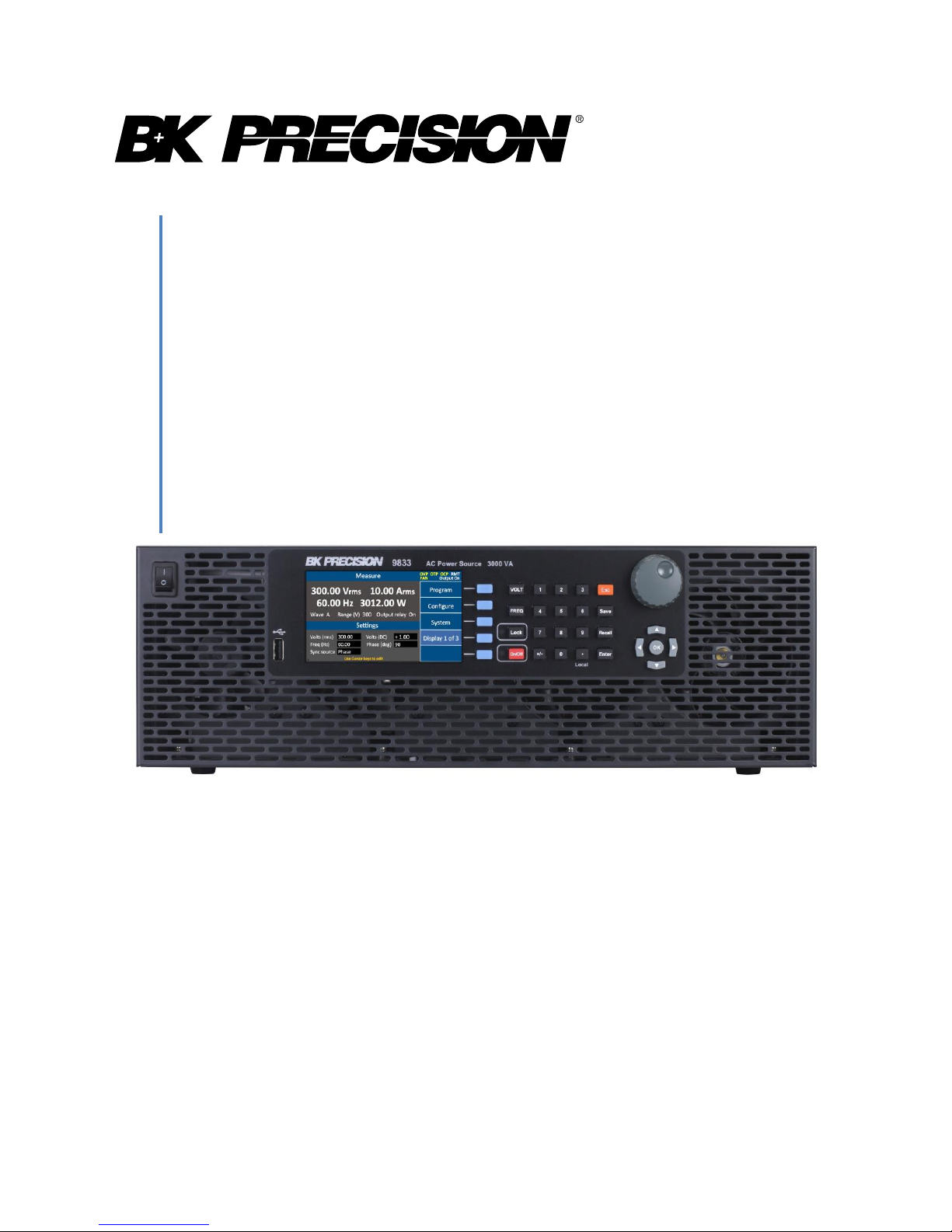
9830 Series
Model: 9832, 9833
High Power Programmable AC Power
Source
USER MANUAL
1
Find Quality Products Online at: sales@GlobalTestSupply.com
www.GlobalTestSupply.com
Page 2

1 Safety Summary
The following safety precautions apply to both operating and maintenance personnel and must
be followed during all phases of operation, service, and repair of this instrument.
Before applying power to this instrument:
Read and understand the safety and operational information in this manual.
Apply all the listed safety precautions.
Verify that the voltage selector at the line power cord input is set to the correct line
voltage. Operating the instrument at an incorrect line voltage will void the warranty.
Make all connections to the instrument before applying power.
Do not operate the instrument in ways not specified by this manual or by B&K Precision.
Failure to comply with these precautions or with warnings elsewhere in this manual violates the
safety standards of design, manufacture, and intended use of the instrument. B&K Precision
assumes no liability for a customer’s failure to comply with these requirements.
Category rating
The IEC 61010 standard defines safety category ratings that specify the amount of electrical
energy available and the voltage impulses that may occur on electrical conductors associated
with these category ratings. The category rating is a Roman numeral of I, II, III, or IV. This rating
is also accompanied by a maximum voltage of the circuit to be tested, which defines the voltage
impulses expected and required insulation clearances. These categories are:
Category I (CAT I): Measurement instruments whose measurement inputs are not intended to
be connected to the mains supply. The voltages in the environment are typically derived from a
limited-energy transformer or a battery.
Category II (CAT II): Measurement instruments whose measurement inputs are meant to be
connected to the mains supply at a standard wall outlet or similar sources. Example
measurement environments are portable tools and household appliances.
Category III (CAT III): Measurement instruments whose measurement inputs are meant to be
connected to the mains installation of a building. Examples are measurements inside a
building's circuit breaker panel or the wiring of permanently-installed motors.
Category IV (CAT IV): Measurement instruments whose measurement inputs are meant to be
connected to the primary power entering a building or other outdoor wiring.
i
Find Quality Products Online at: sales@GlobalTestSupply.com
www.GlobalTestSupply.com
Page 3

Do not use this instrument in an electrical environment with a higher category rating than what
is specified in this manual for this instrument.
You must ensure that each accessory you use with this instrument has a category rating equal
to or higher than the instrument's category rating to maintain the instrument's category rating.
Failure to do so will lower the category rating of the measuring system.
Electrical Power
This instrument is intended to be powered from a CATEGORY II mains power environment. The
mains power should be between 190 V to 250 V RMS. Use only the power cord supplied with
the instrument and ensure it is appropriate for your country of use.
Ground the Instrument
To minimize shock hazard, the instrument chassis and cabinet must be connected to an
electrical safety ground. This instrument is grounded through the ground conductor of the
supplied, three-conductor AC line power cable. The power cable must be plugged into an
approved three-conductor electrical outlet. The power jack and mating plug of the power cable
meet IEC safety standards.
Do not alter or defeat the ground connection. Without the safety ground connection, all
accessible conductive parts (including control knobs) may provide an electric shock. Failure to
use a properly-grounded approved outlet and the recommended three-conductor AC line
power cable may result in injury or death.
Unless otherwise stated, a ground connection on the instrument's rear panel is for a reference
of potential only and is not to be used as a safety ground.
Do not operate in an explosive or flammable atmosphere
ii
Find Quality Products Online at: sales@GlobalTestSupply.com
www.GlobalTestSupply.com
Page 4
Do not operate the instrument in the presence of flammable gases or vapors, fumes, or finelydivided particulates.
The instrument is designed to be used in office-type indoor environments. Do not operate the
instrument
In the presence of noxious, corrosive, or flammable fumes, gases, vapors, chemicals, or
finely-divided particulates.
In relative humidity conditions outside the instrument's specifications.
In environments where there is a danger of any liquid being spilled on the instrument or
where any liquid can condense on the instrument.
In air temperatures exceeding the specified operating temperatures.
In atmospheric pressures outside the specified altitude limits or where the surrounding
gas is not air.
In environments with restricted cooling air flow, even if the air temperatures are within
specifications.
In direct sunlight.
This instrument is intended to be used in an indoor pollution degree 2 environment. The
operating temperature range is 0 °C to 40 °C and 20% to 80% relative humidity, with no
condensation allowed.
Measurements made by this instrument may be outside specifications if the instrument is used
in non-office-type environments. Such environments may include rapid temperature or
humidity changes, sunlight, vibration and/or mechanical shocks, acoustic noise, electrical noise,
strong electric fields, or strong magnetic fields.
Do not operate instrument if damaged
If the instrument is damaged, appears to be damaged, or if any liquid, chemical, or other
material gets on or inside the instrument, remove the instrument's power cord, remove the
instrument from service, label it as not to be operated, and return the instrument to B&K
Precision for repair. Notify B&K Precision of the nature of any contamination of the instrument.
iii
Find Quality Products Online at: sales@GlobalTestSupply.com
www.GlobalTestSupply.com
Page 5

Clean the instrument only as instructed
Do not clean the instrument, its switches, or its terminals with contact cleaners, abrasives,
lubricants, solvents, acids/bases, or other such chemicals. Clean the instrument only with a
clean dry lint-free cloth or as instructed in this manual.
Not for critical applications
This instrument is not authorized for use in contact with the human body or for use as a
component in a life-support device or system.
Do not touch live circuits
Instrument covers must not be removed by operating personnel. Component replacement and
internal adjustments must be made by qualified service-trained maintenance personnel who
are aware of the hazards involved when the instrument's covers and shields are removed.
Under certain conditions, even with the power cord removed, dangerous voltages may exist
when the covers are removed. To avoid injuries, always disconnect the power cord from the
instrument, disconnect all other connections (for example, test leads, computer interface
cables, etc.), discharge all circuits, and verify there are no hazardous voltages present on any
conductors by measurements with a properly-operating voltage-sensing device before touching
any internal parts. Verify the voltage-sensing device is working properly before and after
making the measurements by testing with known-operating voltage sources and test for both
DC and AC voltages. Do not attempt any service or adjustment unless another person capable
of rendering first aid and resuscitation is present.
Do not insert any object into an instrument's ventilation openings or other openings.
Hazardous voltages may be present in unexpected locations in circuitry being tested when a
fault condition in the circuit exists.
Fuse replacement
iv
Find Quality Products Online at: sales@GlobalTestSupply.com
www.GlobalTestSupply.com
Page 6

Fuse replacement must be done by qualified service-trained maintenance personnel who are
aware of the instrument's fuse requirements and safe replacement procedures. Disconnect the
instrument from the power line before replacing fuses. Replace fuses only with new fuses of
the fuse types, voltage ratings, and current ratings specified in this manual or on the back of the
instrument. Failure to do so may damage the instrument, lead to a safety hazard, or cause a
fire. Failure to use the specified fuses will void the warranty.
Servicing
Do not substitute parts that are not approved by B&K Precision or modify this instrument.
Return the instrument to B&K Precision for service and repair to ensure that safety and
performance features are maintained.
For continued safe use of the instrument
Do not place heavy objects on the instrument.
Do not obstruct cooling air flow to the instrument.
Do not place a hot soldering iron on the instrument.
Do not pull the instrument with the power cord, connected probe, or connected test
lead.
Do not move the instrument when a probe is connected to a circuit being tested.
v
Find Quality Products Online at: sales@GlobalTestSupply.com
www.GlobalTestSupply.com
Page 7
This product is subject to Directive 2002/96/EC of the
European Parliament and the Council of the European
Union on waste electrical and electronic equipment
(WEEE), and in jurisdictions adopting that Directive, is
marked as being put on the market after August 13, 2005,
and should not be disposed of as unsorted municipal waste.
Please utilize your local WEEE collection facilities in the
disposition of this product and otherwise observe all
applicable requirements.
Compliance Statements
Disposal of Old Electrical & Electronic Equipment (Applicable in the European
Union and other European countries with separate collection systems)
CE Declaration of Conformity
This instrument meets the requirements of EMC Directive 2014/30/EU Electromagnetic
Compatibility Directive and the following standards.
EMC Directive
- EN 61326-1:2013 Class A
- EN 61326-2-1:2013
- EN 61000-3-12:2011
- EN 61000-3-11:2000
- EN 61326-1:2013 (industrial locations)
- EN 610000-4-2:2009
- EN 610000-4-3:2006+A1:2008+2010
- EN 610000-4-4:2012
- EN 610000-4-5:2014
Find Quality Products Online at: sales@GlobalTestSupply.com
- EN 610000-4-6:2010
- EN 610000-4-8:2010
- EN 610000-4-34:2007+A1:2009
vi
www.GlobalTestSupply.com
Page 8
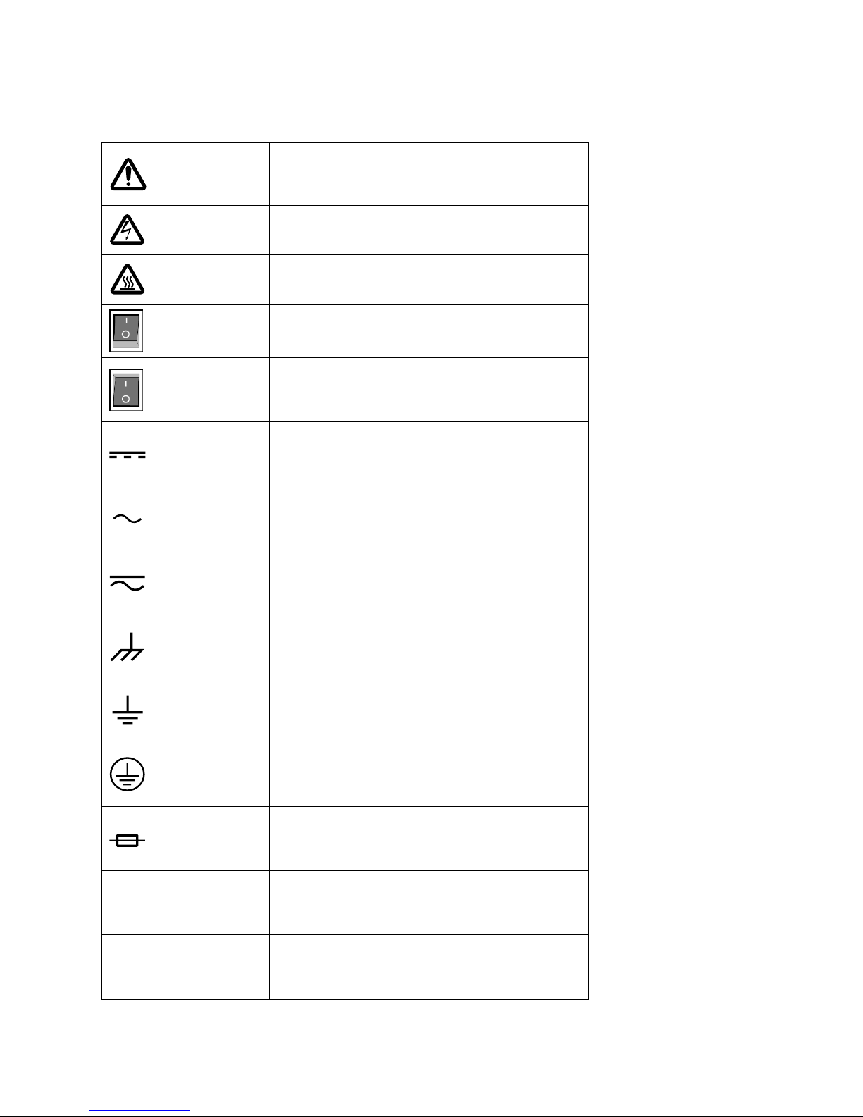
Refer to the user manual for warning
information to avoid hazard or personal
injury and prevent damage to instrument.
Electric Shock hazard
Hot surface
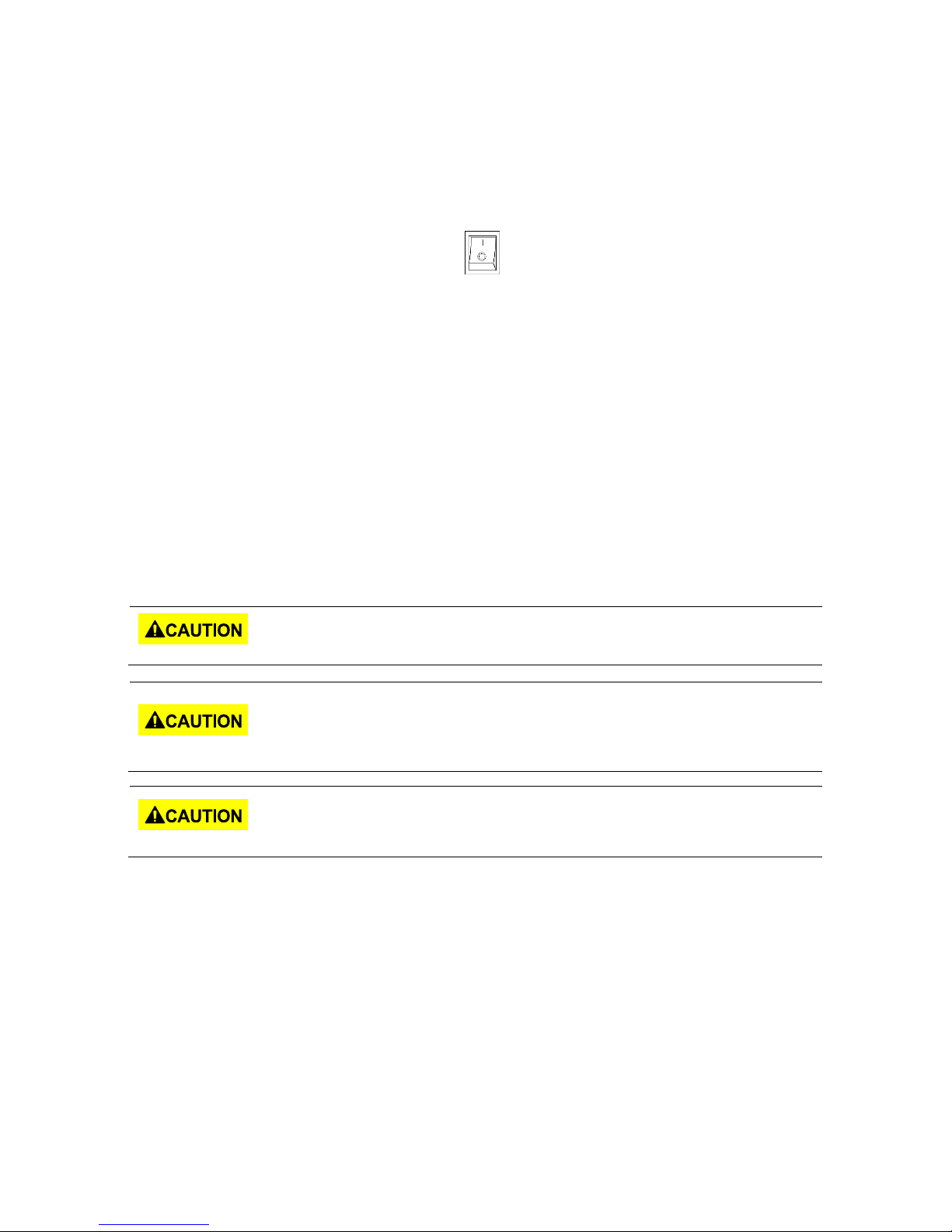
On (Power). Press the “I” at the top of the
power switch to turn the instrument ON.
Off (Power). Press the “O” at the bottom of
the power switch to turn the instrument
off.
Direct current (DC)
Alternating current (AC)
Direct and alternating current (DC + AC)
Chassis (earth ground) symbol
Ground terminal
Protective earth ground
Fuse Symbol
CAT I
(1000V)
IEC Measurement Category I. Inputs may be
connected to mains (up to 1000 VAC) under
Category I overvoltage conditions.
CAT II
(300V)
IEC Measurement Category II. Inputs may
be connected to mains (up to 300 VAC)
under Category II overvoltage conditions.
Safety Symbols
Find Quality Products Online at: sales@GlobalTestSupply.com
www.GlobalTestSupply.com
vii
Page 9
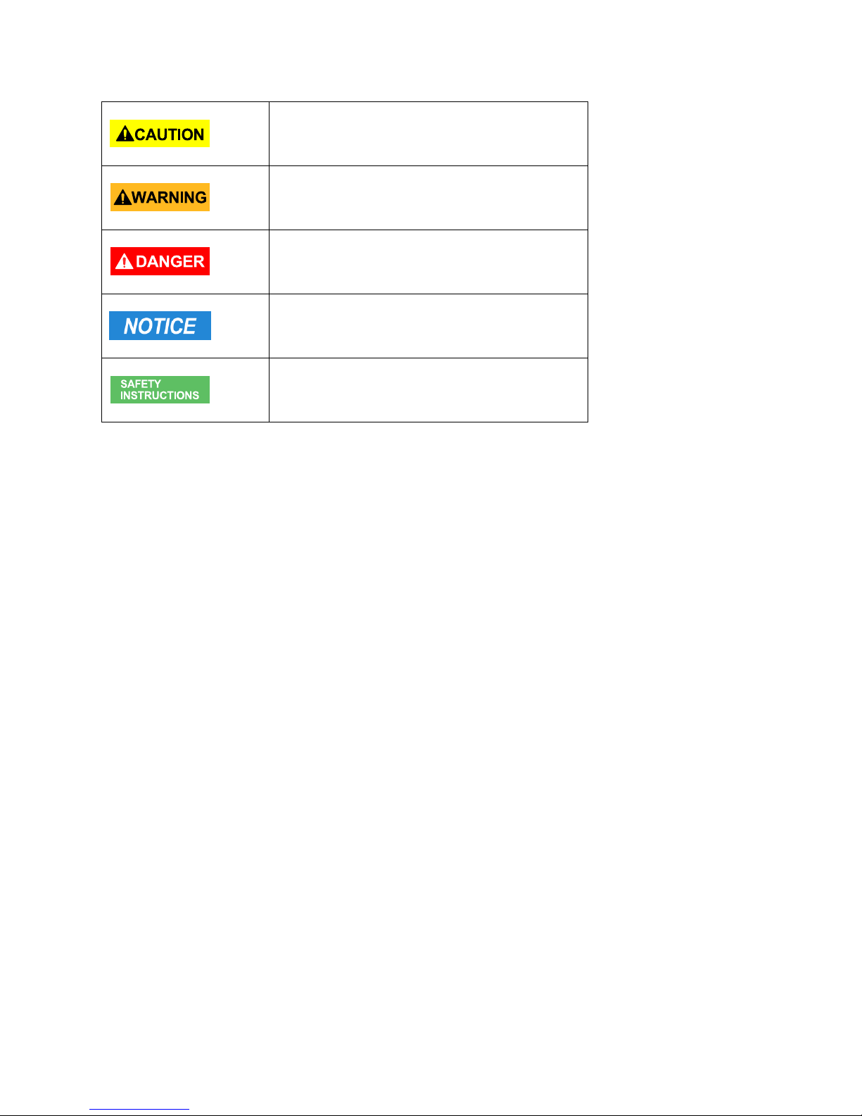
CAUTION indicates a hazardous situation
which, if not avoided, will result in minor or
moderate injury
WARNING indicates a hazardous situation
which, if not avoided, could result in death
or serious injury
DANGER indicates a hazardous situation
which, if not avoided, will result in death or
serious injury.
NOTICE is used to address practices not
related to physical injury.
Safety instructions (or equivalent) signs
indicate specific safety-related instructions
or procedures
Find Quality Products Online at: sales@GlobalTestSupply.com
www.GlobalTestSupply.com
viii
Page 10

2 Notations
TEXT – Denotes a softkey.
TEXT – Denotes a front panel key.
ix
Find Quality Products Online at: sales@GlobalTestSupply.com
www.GlobalTestSupply.com
Page 11

Table of Contents
1 Safety Summary ............................................................................................................... i
Compliance Statements ............................................................................................................... vi
Safety Symbol ............................................................................................................................. vii
2 Notations ........................................................................................................................ ix
3 General Information ........................................................................................................ 1
3.1 Package Contents .............................................................................................................. 1
3.2 Product Dimensions ........................................................................................................... 2
3.3 Installation ......................................................................................................................... 3
3.4 Front Panel......................................................................................................................... 4
3.5 Rear Panel .......................................................................................................................... 6
4 Display Overview ............................................................................................................ 7
4.1 Display Description ............................................................................................................ 7
5 Getting Started.............................................................................................................. 10
5.1 Input Power Requirements ............................................................................................. 10
5.1.1 North American Split Phase Power .................................................................... 10
5.1.2 Fuse .................................................................................................................... 12
5.2 Preliminary Check ............................................................................................................ 12
5.2.1 Power-on Procedure .......................................................................................... 12
5.2.2 Warm-up Time ................................................................................................... 13
5.2.3 Power-off Procedure .......................................................................................... 13
5.3 Sense Lines ....................................................................................................................... 13
6 Menu Tree .................................................................................................................... 15
7 Front Panel Operation ................................................................................................... 16
7.1 Configure Voltage and Frequency Output....................................................................... 16
7.1.1 Setting voltage .................................................................................................... 16
7.1.2 Setting frequency ............................................................................................... 16
7.1.3 Setting Voltage ................................................................................................... 17
7.2 Program Settings ............................................................................................................. 18
7.2.1 Step Mode .......................................................................................................... 18
7.2.2 List Mode ............................................................................................................ 20
7.2.3 Pulse Mode ......................................................................................................... 25
8 Configure Menu ............................................................................................................ 27
x
Find Quality Products Online at: sales@GlobalTestSupply.com
www.GlobalTestSupply.com
Page 12

8.1 Config 1 ............................................................................................................................ 27
8.2 Config 2 ............................................................................................................................ 29
8.3 Limits ................................................................................................................................ 31
9 System Settings ............................................................................................................. 33
9.1 System Setup ................................................................................................................... 33
9.2 Communication Setup ..................................................................................................... 33
9.3 System Error .................................................................................................................... 34
9.4 System Next ..................................................................................................................... 35
9.5 Recall Default ................................................................................................................... 36
10 Save .............................................................................................................................. 38
10.1 Save Config ...................................................................................................................... 38
10.2 Save Screen ...................................................................................................................... 39
10.3 Recall Configuration ........................................................................................................ 39
11 Remote Interface Operation .......................................................................................... 41
11.1 Interface Connection ....................................................................................................... 41
11.1.1 RS232 ................................................................................................................. 41
11.1.2 USBVCP (virtual COM) ....................................................................................... 41
11.1.3 USBTMC ............................................................................................................. 42
11.1.4 GPIB ................................................................................................................... 42
11.1.5 LAN (Ethernet) ................................................................................................... 42
11.1.6 Web server ......................................................................................................... 42
12 Digital I/O ..................................................................................................................... 46
12.1 External Voltage Control.................................................................................................. 47
12.1.1 AC Couple........................................................................................................... 48
12.1.2 DC Couple .......................................................................................................... 48
12.2 Trigger In .......................................................................................................................... 48
12.3 15 VDC ............................................................................................................................. 49
12.4 Output Status Detection .................................................................................................. 49
12.4.1 /SYNC ................................................................................................................. 50
12.4.2 /Fault_out .......................................................................................................... 50
12.4.3 /Transient .......................................................................................................... 50
12.5 Remote_Inhibit ................................................................................................................ 51
12.6 Tx / Rx .............................................................................................................................. 52
12.7 Event_SW ......................................................................................................................... 52
12.8 Analog input (BNC) .......................................................................................................... 53
xi
Find Quality Products Online at: sales@GlobalTestSupply.com
www.GlobalTestSupply.com
Page 13

13 Build-in Harmonic Wave ................................................................................................ 55
14 Calibration .................................................................................................................... 70
14.1 AC Voltage Calibration ..................................................................................................... 70
14.1.1 300V range calibration ...................................................................................... 71
14.1.2 150V range calibration ...................................................................................... 72
14.1.3 DC Voltage Calibration ....................................................................................... 72
14.1.4 AC Current Calibration ....................................................................................... 73
14.1.5 Restore to Factory Default (RECALL DATA) ....................................................... 74
14.1.6 External Voltage Calibration .............................................................................. 75
15 Specifications ................................................................................................................ 78
16 LIMITED THREE-YEAR WARRANTY ................................................................................. 81
xii
Find Quality Products Online at: sales@GlobalTestSupply.com
www.GlobalTestSupply.com
Page 14

3 General Information
The B&K Precision 9830 series are low distortion single phase AC power sources delivering a
maximum of 3000 VA, 300 Vrms, 30 Arms /97.5 Apk. The Output frequency is adjustable from
45 Hz to 1200 Hz. All models are capable of outputting AC, DC or AC+DC. Predefined waveforms
include sine, square, clipped sine and THD waveforms. Standard remote interface include
USBVCP and USBTMC-compliant. RS232, LAN, and GPIB interfaces are available to provide
flexibility for remote operation.
Features
Output AC, DC or AC+DC
Built-in power factor correction (PFC) circuit at the AC input
Low harmonic distortion
Power Line Disturbance simulation
Step, pulse and list modes
Adjustable phase angle control
Built-in and user definable waveforms
Digital I/O port for external trigger, remote inhibit, command completion, failure status,
Analog input for external control
Comprehensive protection modes including OVP, OCP, OTP, fan failure, key lock
3.1 Package Contents
Please inspect the instrument mechanically and electrically upon receiving it. Unpack all items
from the shipping carton, and check for any obvious signs of physical damage that may have
occurred during transportation. Report any damage to the shipping agent immediately. Save
the original packing carton for possible future reshipment. Every instrument is shipped with the
following contents:
1 x 9833 or 9832 AC Power Source
1 x AC input power cord
1 x Certificate of calibration
1 x Test report
Verify that all items above are included in the shipping container. If anything is missing, please
contact B&K Precision.
1
Find Quality Products Online at: sales@GlobalTestSupply.com
www.GlobalTestSupply.com
Page 15
Note: Check that you have the most current User manual.
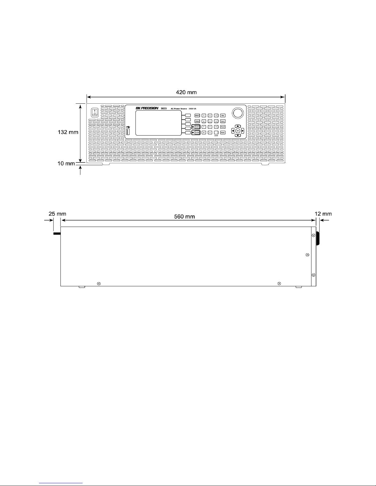
3.2 Product Dimensions
Figure 1 - Dimensions
2
Find Quality Products Online at: sales@GlobalTestSupply.com
www.GlobalTestSupply.com
Page 16
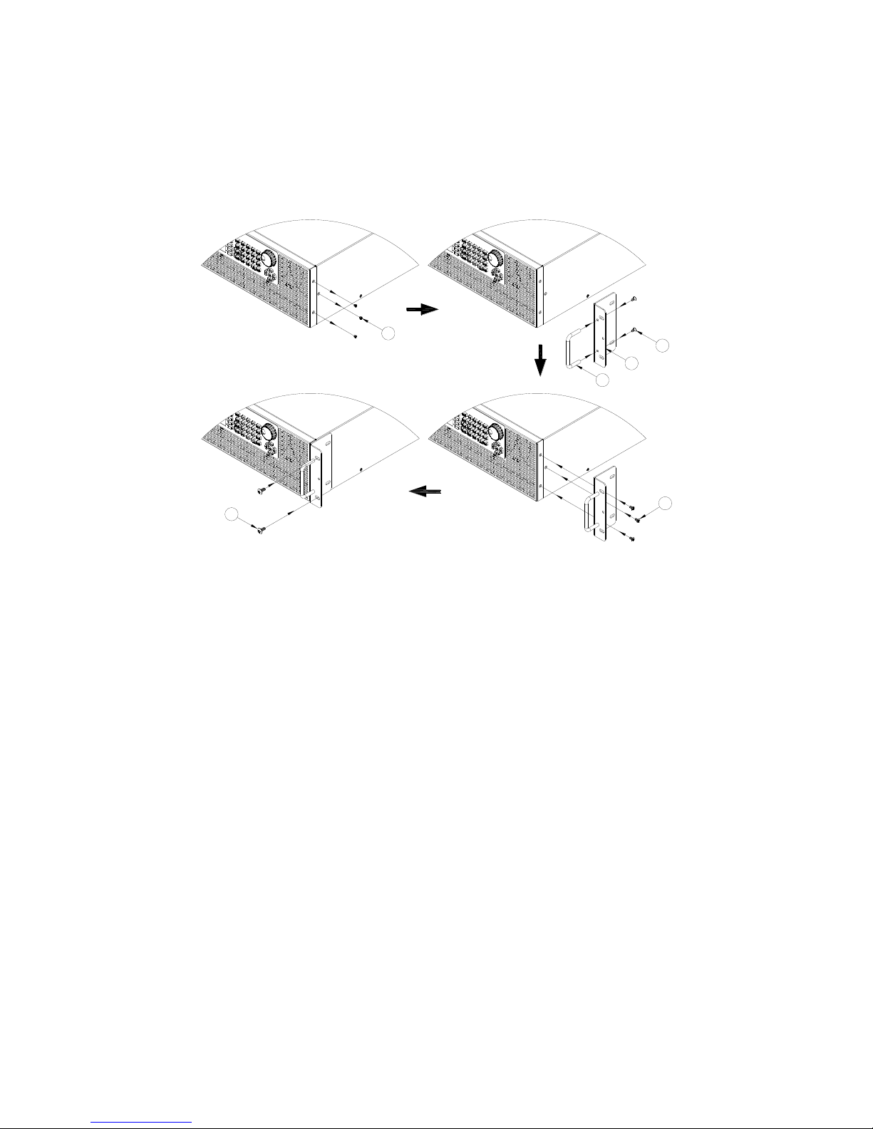
1
Step 1
2
3
4
Step 2
5
Step 3Step 4
6
3.3 Installation
The following diagram shows how to install the optional rack mount kit.
Figure 2 - Rack Mount Kit
3
Find Quality Products Online at: sales@GlobalTestSupply.com
www.GlobalTestSupply.com
Page 17

①
Power ON/OFF
②
USB disk port
③
VFD
④
Softkeys
⑤
Function keys & Indicator LEDs
⑥
Number keys
⑦
Function keys
⑧
Rotary knob
⑨
Direction keys
3.4 Front Panel
Figure 3 - Front Panel
4
Find Quality Products Online at: sales@GlobalTestSupply.com
www.GlobalTestSupply.com
Page 18
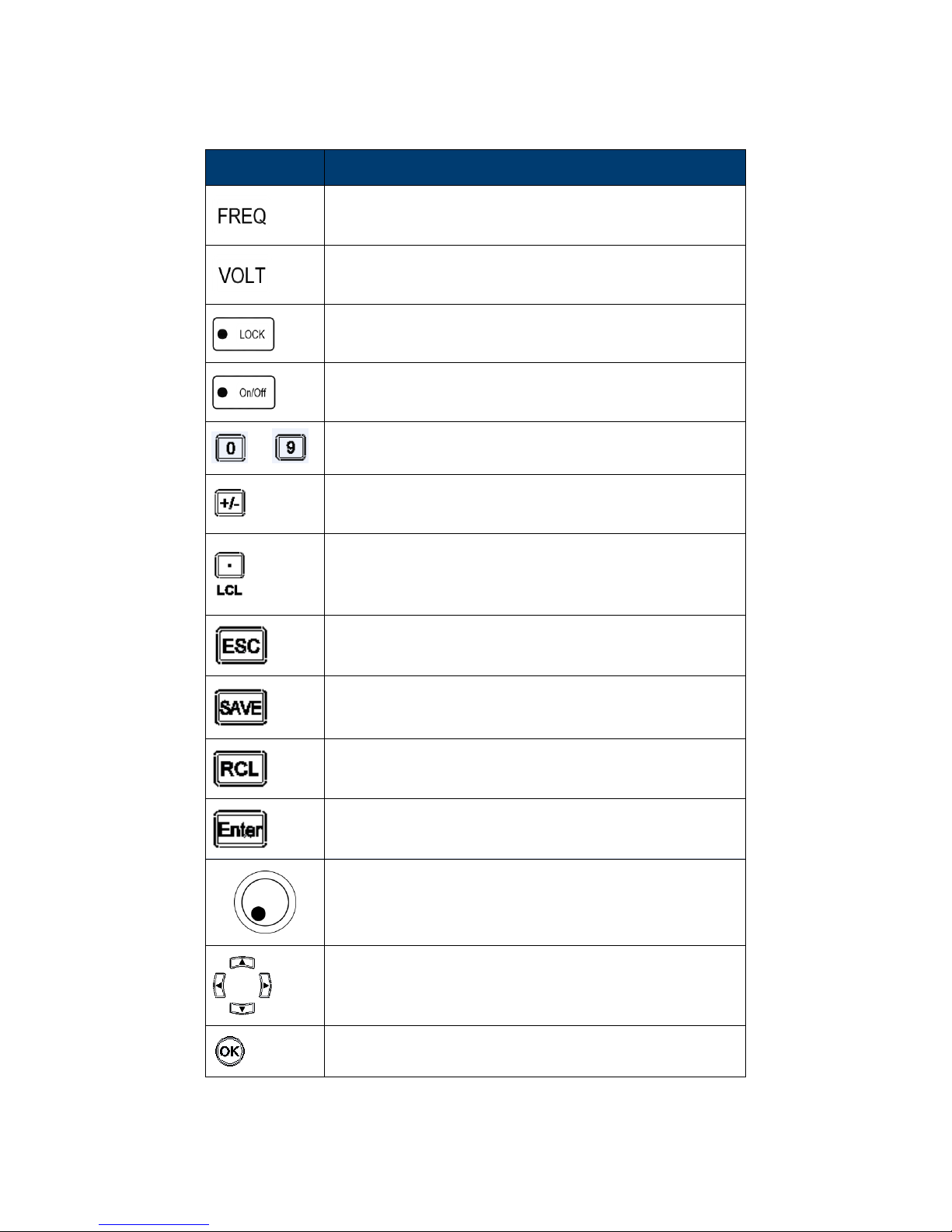
Key
Definition
Frequency key, press to set the output frequency
Voltage key, press to set the output voltage
Press to lock the keyboard,
(Keyboard is locked when LED is illuminated).
Output On/Off key, press to enable/disable voltage
output, (Output is On when LED is illuminated).
to
Number key 1 to 9 for direct numeric entry.
Set the number entered to a positive or negative
value.
Main function: decimal point
Secondary function: switch from remote control to
local control
Escape key, press to escape the settings menu or
cancel the current settings
Save key, store configurations and settings into the
internal memory or a USB disk
Recall key, recall data from internal storage or
external USB disk
Enter key, press to confirm the settings change
Rotary, to adjust value or make up/down selection
(press it for ENTER function)
Up/Down/Left/Right direction keys
Confirm key, press to confirm the settings
Find Quality Products Online at: sales@GlobalTestSupply.com
www.GlobalTestSupply.com
5
Page 19
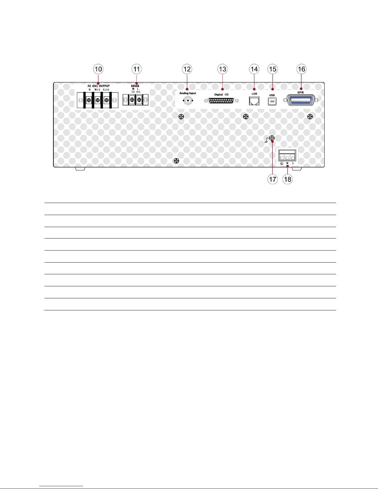
⑩
AC output terminal
⑪
Remote sense terminal
⑫
ANALOG connector
⑬
DIGITAL Input /Output
⑭
LAN port
⑮
USB port (USBVCP or USBTMC)
⑯
GPIB port
⑰
Ground wire
⑱
AC input terminal
3.5 Rear Panel
Figure 4 - Rear Panel
6
Find Quality Products Online at: sales@GlobalTestSupply.com
www.GlobalTestSupply.com
Page 20
4 Display Overview
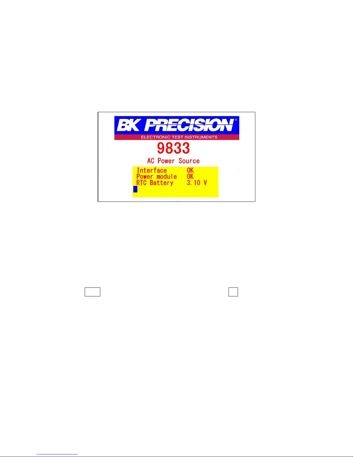
The power on screen shows the model number and self-test status. The Interface, and Power
module should indicate OK. The (Real Time Clock), RTC will show the battery voltage. When the
self-test completes, the instrument will advance to the Settings and Measure screen. This
process takes approximately 7 seconds. If an error does occur, the instrument must be returned
for service.
Figure 5 - Power on screen
4.1 Display Description
At the top right of the screen the remote and output status are displayed. Each of the blue
softkeys will have a corresponding label to the left. These labels will change on each screen to
show different options. Settings Fields have a black background. Settings Fields can be selected
by using arrow keys to move to the field and press enter to select and modify the value in the
field. Press the Enter key again to confirm the change or press the Esc key to cancel the change.
7
Find Quality Products Online at: sales@GlobalTestSupply.com
www.GlobalTestSupply.com
Page 21
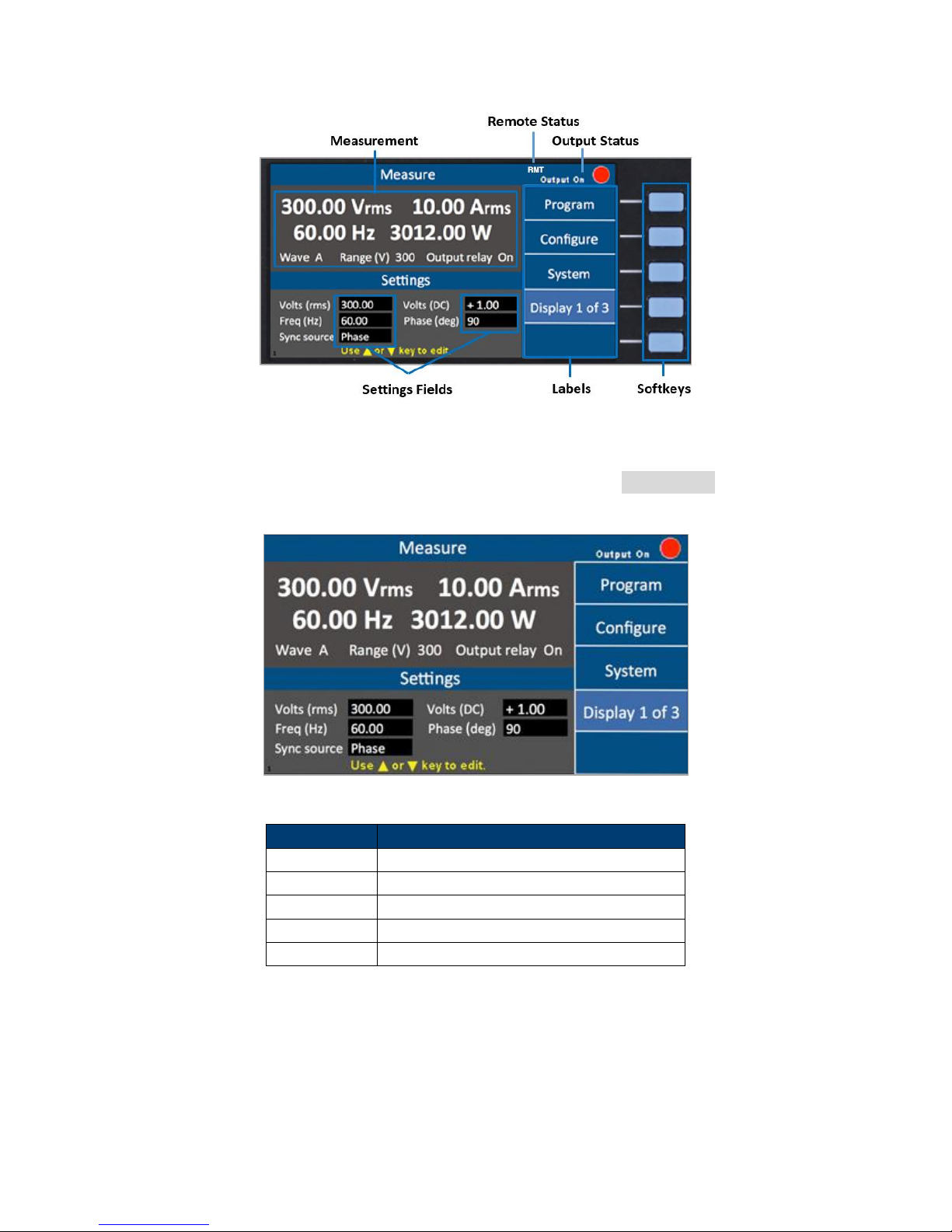
Parameter
Description
Volts (rms)
AC output Vrms setting
Volts (DC)
DC output setting
Freq (Hz)
Output frequency setting
Sync source
Select Phase or Immed (immediate)
Phase (deg)
Phase angle setting
Figure 6 - Display Description
The instrument provides 3 display screen options for accessing commonly used measurements
and settings. Each of these screens can be selected by pressing the Display x of x softkey
repeatedly.
Figure 7 - Display 1 of 3
Table 1 – Display 1 of 3 Settings
Display 2 of 3
This display shows all 12 power measurements and an output timer.
8
Find Quality Products Online at: sales@GlobalTestSupply.com
www.GlobalTestSupply.com
Page 22
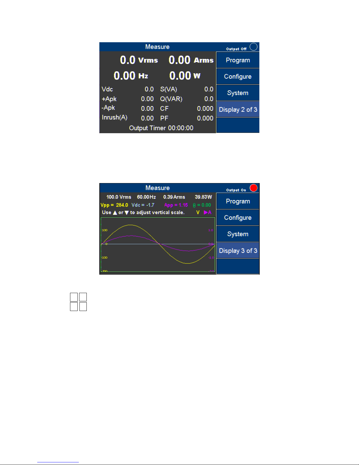
Figure 8 - Display 2 of 3
Display 3 of 3
This displays shows a graphical representation of the settings, output measurements and
waveforms.
Figure 9 - Display 3 of 3
Press the ◄ ► keys to select and view V (voltage waveform) or A (current waveform). Then
press the ▲ ▼ key to change the scale until the complete waveform is visible.
9
Find Quality Products Online at: sales@GlobalTestSupply.com
www.GlobalTestSupply.com
Page 23
Connection of the 9832 or 9833 to an AC power source should be made by a
qualified electrician or other qualified personnel. Incorrect wiring may damage the
source or cause a fire hazard.
The included AC power cord is safety certified for this instrument operating in the
rated range. If an extension cable is added, be sure that it can meet the required
power ratings for this instrument. Any misuse with wrong or unsafe cables will
void the warranty.
5 Getting Started
Before connecting and powering up the instrument, please review and go through the
instructions in this chapter.
5.1 Input Power Requirements
The AC input accepts line voltage input within:
Voltage: 190 V – 250 V
Frequency: 47 Hz – 63 Hz
Maximum power consumption: 9832: 2500 VA; 9833: 3800 VA
Before connecting to an AC outlet or external power source, make sure that the power switch is
in the OFF position and verify that the AC power cord, including the extension line, is
compatible with the rated voltage/current and that there is sufficient circuit capacity for the
power supply.
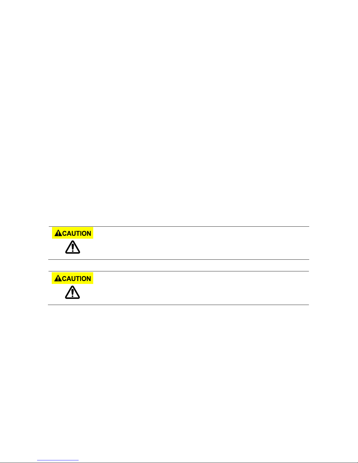
Follow the illustrations below to connect the new AC power cord to the AC input of the source
in the rear panel.
5.1.1 North American Split Phase Power
Split phase is commonly used in North American to provide 208 to 240 Volts. This
requires two wires that are both hot. For example 110 V and, 110 V resulting in 220 V
across them. The included cable may be used in most regions by adding a band of blue
electrical tape on each end of the white wire to identify both the black and white with
blue band as hot. The green trace yellow wire is always used for ground and must be
connected properly. Check with your local Authority Having Jurisdiction for clarification.
The power cable that is shipped with the instrument is preassembled from the factory.
The following instruction will provide information for changing the power cable for split
phase.
1. Verify that the source power in your facility can provide the minimum voltage and
Find Quality Products Online at: sales@GlobalTestSupply.com
www.GlobalTestSupply.com
10
Page 24
current required to operate the instrument.
2. Using the power cable provided, identify the end that plugs into the instrument.
Before disassembling the black hooded connector, make a note of how the unit is
assembled from the factory so it can be correctly reassembled.
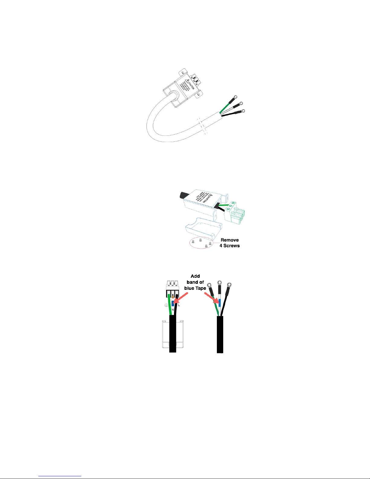
3. Remove the 4 screws from the bottom of the hooded connector as shown and place
the upper and the upper and lower hood pieces and screws to the side.
The black, white, and green wires should now be clearly visible. Use a screwdriver to
unscrew and release the white wire only.
Add a band of blue electrical tape or heat shrink to each end of the white wire.
1. Return the white wire into the green connecter and tighten the screw. Verify all
three wires are secured in the connector.
2. Closely inspect each of the wires at the enter point of the green connector to
verify none of the copper strands are bridging over to the wrong terminal
causing a short.
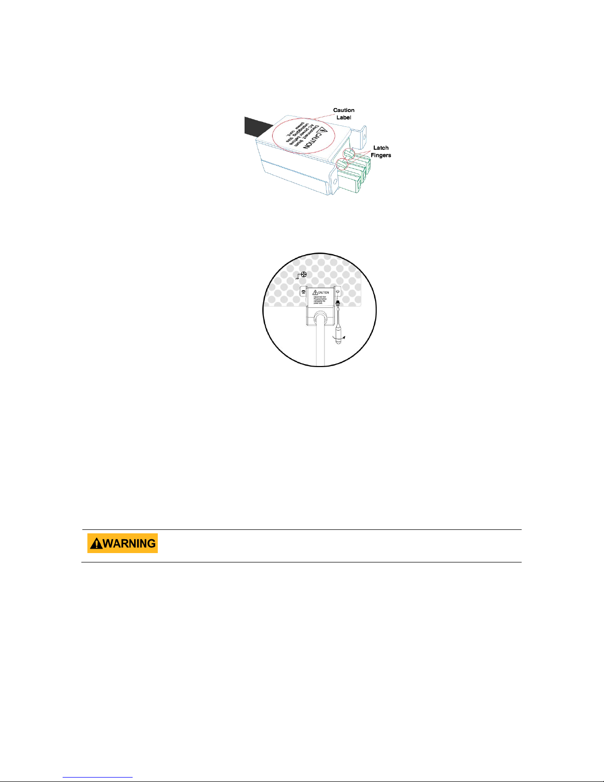
3. Carefully reassemble the hood so the Latch Fingers and Caution Label are facing
11
Find Quality Products Online at: sales@GlobalTestSupply.com
www.GlobalTestSupply.com
Page 25
Any disassembling of the case or fuse changes not performed by an authorized
service technician will void the warranty of the instrument.
up and reinstall the 4 screws into the hood. The green connector should be
locked in place.
4. Using the (2) screws provided with the cable, secure the assembled connector to
the back of the instrument as shown in Figure 10 – Securing. Note: Use only the
screws provided.
The green (trace yellow) wire connects to electrical ground (required). The black wire
connects to L (Line 1) and the white with blue band connects to N (Line 2).
5.1.2 Fuse
The factory installed fuse will meet the requirements when the instrument is operated
with the specified Input Power requirements. This source is a switching mode power
supply. The fuse installed inside should not fail under normal operation. If the fuse has
blown, it may be an indication of a more serious malfunction inside of the source. In this
event, contact B&K Precision.
5.2 Preliminary Check
5.2.1 Power-on Procedure
1. Complete the following steps to verify that the source is ready for use.
2. Verify AC Input Voltage
Figure 10 - Securing the power cable
3. Verify and check to make sure proper AC voltages are available to power the
12
Find Quality Products Online at: sales@GlobalTestSupply.com
www.GlobalTestSupply.com
Page 26
Do not connect multiple power supplies in series or parallel as this may cause
damage or a malfunction.
When the AC input voltage is lower than 190 VAC, the source will activate an inner
over temperature protector and cut off the output in response to the condition. To
ensure that the entire test process can be completed smoothly, confirm that the
input AC voltage is within the specified range.
When the AC input frequency is outside the range of 47 to 63 Hz, the source will
beep. To ensure the normal operation of the source, please make sure the AC
input frequency is within the required range.
instrument. The AC voltage range must meet per the acceptable specifications.
4. Connect Power
5. Connect specified AC power cord and verify the hood is in place and correctly
secured to rear panel.
6. Press the power switch to the “|” ON position to turn ON the instrument.
It will take a few seconds before the fans power on and the self-test begins.
5.2.2 Warm-up Time
The 9830 series is fully operable upon switching the power on. However, to reach the
specified equipment accuracy, please allow the source to warm up for at least 15
minutes.
5.2.3 Power-off Procedure
When the instrument is not in use, make sure to set the front panel power switch to the
OFF position. After the power switch is turned off the internal fans will continue to run
for approximately 5-10 seconds to discharge the internal capacitors per safety
requirements. Once the discharge process is complete, the instrument will carry out an
automatic shutdown process of approximately 2-8 seconds. Do not turn the power back
on until the instrument has completed a full shut down cycle.
5.3 Sense Lines
The source can be configured as local sense or remote sense to compensate the voltage
drop of the test leads. The following diagram shows how to connect the load by local sense
or remote sense configurations.
When local sense is selected, the sense end L is connected to the output end L and sense
end N is connected to the output end N, whereas the output end L is connected to the load
end L and output end N is connected to the load end N. When this sensing mode is
selected, the wires connecting between the sense ends to the load end must be as short as
possible. The local sense is the default configuration. When remote sense is selected, both
Find Quality Products Online at: sales@GlobalTestSupply.com
www.GlobalTestSupply.com
13
Page 27
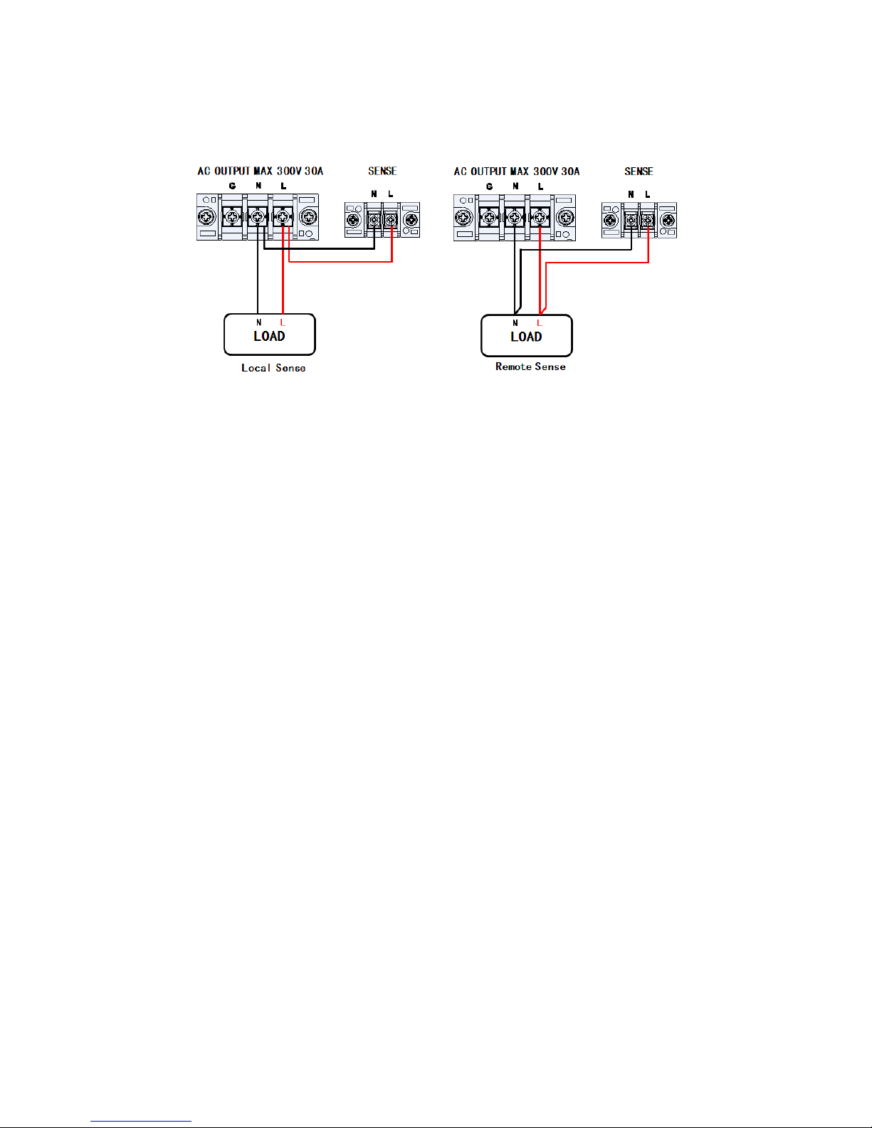
the sense end L and output end L are connected to the load end L, whereas both sense end
N and output end N are connected to the load end N.
Figure - 11 Sense Lines
14
Find Quality Products Online at: sales@GlobalTestSupply.com
www.GlobalTestSupply.com
Page 28
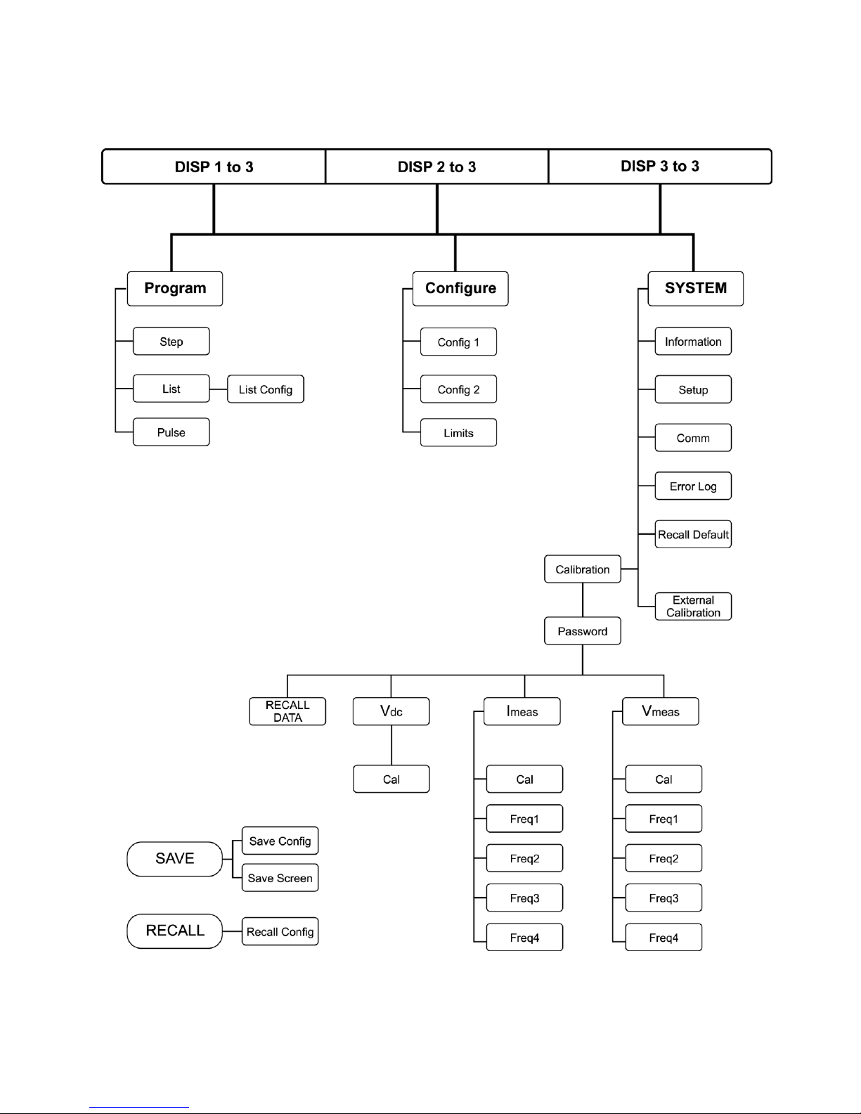
6 Menu Tree
15
Find Quality Products Online at: sales@GlobalTestSupply.com
www.GlobalTestSupply.com
Page 29

NOTES:
1) The values of some settings are strings, for example, Sync Source = IMMED (or PHASE). These
settings can be set by the arrow keys (▲ ▼ ◄ ►) or the rotary knob.
2) When the output status is ON, any changes to the displayed values of Volts(rms), Volts(DC) or
FREQ are immediately reflected at the output.
3) Except for Volts(rms), Volts(DC) and FREQ, the ENTER key must be pressed to confirm the new
output value and save the new settings to memory. Changes can be cancelled by pressing the ESC
key before the ENTER key.
7 Front Panel Operation
7.1 Configure Voltage and Frequency Output
7.1.1 Setting voltage
Press VOLT or the ▲ ▼ (arrow keys) to move the cursor to Volts (rms). Then press the
ENTER key.
There are three ways to set the value of the output voltage:
1. Press the number keys 1, 1, 0, . , 0 and Enter to set Volts(rms) = 110.0 V.
2. Use the ◄ ► keys to select the hundreds digit then press the arrow keys ▲ or
▼ repeatedly until the value reaches 110.0 and press the Enter or OK key to
confirm.
3. Use ◄ ► keys to the hundreds digit then use the rotary knob until the value
reaches 110.0. Press the Enter or OK key or push in on the rotary knob to
confirm.
7.1.2 Setting frequency
Press FREQ or arrow key (▲ ▼) to move the cursor to the Freq (Hz). Then press the
ENTER or OK key.
There are three ways to set the value of output frequency:
1. Press number key 6, 0, Enter or OK to set Freq (Hz) = 60.
2. Use ◄ ► keys to the hundreds digit then press arrow keys (▲or ▼) repeatedly
until the value reaches 60. Press Enter or OK key to confirm.
Use ◄ ► keys to select the hundreds digit then rotate the rotary knob until the value
reaches 60. Press Enter or OK key or press in on the rotary knob to confirm the change.
Find Quality Products Online at: sales@GlobalTestSupply.com
www.GlobalTestSupply.com
16
Page 30

Vac
7.1.3 Setting Voltage
Press the VOLT key, and a small window will pop-up. Pressing the VOLT key again will
switch between VAC and VDC (when the coupling mode is “AC+DC”). Press the number
keys to set the value, and press the OK or the Enter key to confirm the change.
Optionally, press the ESC key to cancel the setting change.
Figure 12 - Setting Frequency
Figure 13 - Setting Voltage. Vac left, Vdc right.
17
Find Quality Products Online at: sales@GlobalTestSupply.com
www.GlobalTestSupply.com
Page 31

Parameters
Range
Description
Volts (rms)
0 to 300.0 Vrms
Initial AC output voltage
dVac
0 to ±300.0 Vrms
In/decrement of VAC per
step
Volts (DC)
-424.0 to 424.0 V
Initial DC output voltage
dVdc
-424.0 to 424.0 V
Increment/decrement of
VDC per step
Freq.
43 to 1200.0 Hz
Initial output frequency
dF
±43 to 1200.0 Hz
Increment/decrement of
FREQ. per step
Set Time
0 to 100000 ms
Set the time interval of
one step
Count
1 to 99
Set how many steps to
run
Sync Source
Immed, Phase
Select the mode of
output transient phase
Phase (deg)
0.0゜ to 359.7゜
Set the angle of output
transient
7.2 Program Settings
Press the Program softkey in the Setting and Measurement page to enter Program mode.
There are three modes for the user to choose from to simulate Power Line Disturbances.
They are:
Step Output settings step-up or step-down based on user criteria.
List Change the output sequentially by individual settings included in a list.
Pulse Trigger pulse signals periodically.
7.2.1 Step Mode
Step Mode has 10 parameters that can be set by the user. The following table describes
each parameter with its range and description.
Table 2 - Step Mode Parameters
18
Find Quality Products Online at: sales@GlobalTestSupply.com
www.GlobalTestSupply.com
Page 32

Parameters
Settings
Volts(rms)
40
dVac
+20
Volts(DC)
+0
dVdc
0
Freq.
50
dF
0.0
Set Time
80
Count
4
Sync Source
Phase
Phase(deg)
0.0
Step Mode Operation Steps
The following example for Step Mode waveform shows 4 steps starting at 40 volts and
increasing 20 volts at each step. The instrument will dwell for 80 ms at each step.
Figure 14 - Step Mode Example Output
Table 3- Step Mode Example Parameters
1. Press the Step softkey.
Figure 15 - Step Page
19
Find Quality Products Online at: sales@GlobalTestSupply.com
www.GlobalTestSupply.com
Page 33

Parameters
Range
Description
List
0 to 9
Index of LIST
Infinite
ON or OFF
ON: Infinite output
OFF: Based on Repeat value
Repeat
0 to 99
Repeat sequence
Base
Time or Cycle
Select the unit for timing the
running of LIST
Sync Source
Immed or Phase
Select the mode of output
transient phase
Phase (deg)
0.0 to 359.7
Set the angle of output transient
2. Use the arrow keys (▲ ▼ ◄ ►) to move the cursor to the wanted parameter of
the STEP setting page.
3. Press the ENTER key to adjust the parameter. Then press the ENTER key again to
change its value.
4. When finished editing all the parameters, press On/Off key to activate the Step
mode.
Using an oscilloscope you should observe a wavfore as shown in Figure 16 - Oscilloscope
view of Step waveform example.
Figure 16 - Oscilloscope view of Step waveform example
The instrument will continuosly output the final waveform of Step mode until the On/Off
key is pressed.
7.2.2 List Mode
List mode is the only mode with two pages of parameters. The first page of parameters
is common to all the Second page parameters. Only one first page is needed per list. The
first page, Table 4 - List Parameters, First Page is displayed when the List softkey is
pressed and the second page, Table 5 - List Config Parameters, Second Page is displayed
when the List Config softkey is pressed.
Table 4 - List Parameters, First Page
20
Find Quality Products Online at: sales@GlobalTestSupply.com
www.GlobalTestSupply.com
Page 34

Parameters
Range
Description
List No.
0 to 9
Show configuration of a LIST
Step No.
0 to 99
Show current edit step of list
Volts (rms) Start
0 to 300
Set starting AC voltage
Volts (rms) End
0 to 300
Set ending AC voltage
Volts (DC) Start
-424.0 to 424.0
Set starting DC voltage
Volts (DC) End
-424.0 to 424.0
Set ending DC voltage
Freq. (Hz) Start
43 to 1200.0
Set starting frequency
Freq. (Hz) End
43 to 1200.0
Set ending frequency
Time (ms)
0 to 999999
Set the time interval for running
the specified configuration
CYCLE
0 to 999999
Set the period for running the
specified configuration
Steps
0 to 200
Set the number of steps the
specified configuration will be
divided into
Parameters
Step 1
Step 2
Step 3
List No.
0 0 0
Step No.
0 1 2
Volts (rms) Start
80
60
40
Volts (rms) End
0 0 0
Volts (DC) Start
0 0 0
Volts (DC) End
0 0 0
Freq. (Hz) Start
50
50
50
Freq. (Hz) End
50
50
50
Time (ms)
100
60
20
Steps
5 3 2
Table 5 - List Config Parameters, Second Page
In the following example 3 new steps will be added to List No. 0.
Figure 17 - List Mode Waveform
Table 6 – Step parameters
Find Quality Products Online at: sales@GlobalTestSupply.com
www.GlobalTestSupply.com
21
Page 35

Parameters
ExampleSettings
List
0
Infinity
OFF
Repeat
02
Base
Time
Sync Source
Phase
Phase (deg)
0.0
Table 7 - List Mode First Page
List operation pages
Press the List softkey, refer to List Parameter Table for settings details.
Figure 18 - List Mode first page
Refer to Table 6 – List Mode First Page. The first page parameters are common to all the
steps added under the second page parameters. This first page only needs to be
configured once for List 0. Use the arrow keys (▲ ▼ ◄ ►) to move the cursor to the
wanted parameter of the List page. Then press the ENTER Key to change its value.
Configure all the parameters for the List mode first page.
When all of the values for the First page have been configured, press List Config softkey
to move to the Second page. The Step No. will indicate “New” as the values have not
been stored in memory yet. Empty Step 100 and current Step 0 will be indicated in the
22
Find Quality Products Online at: sales@GlobalTestSupply.com
www.GlobalTestSupply.com
Page 36

Parameters
Values
Volts (rms) Start
80
Volts (rms) End
0
Volts (DC) Start
0
Volts (DC) End
0
Freq. (Hz) Start
50
Freq. (Hz) End
50
Time (ms)
100
Steps
5
yellow boxes when no entries are stored in any List.
Figure 19 - List Mode second page
Refer to . Use the arrow key (▲ ▼ ) to move the cursor to the wanted parameter of List
Step Configuration page. Press the ENTER key to change its value, then press the ENTER
key again to confirm the change.
Figure - List 0, User Step 1 Values
After all of the values from have been entered, press the Add Step softkey to enter all
the changes in to memory and create a new step in List No. 0. The Empty Step will
change to 99 and Current Step will change to 1.
Figure 20 – List Mode Add Step
Refer to Figure 21 - List 0, Step 2 Values
23
Find Quality Products Online at: sales@GlobalTestSupply.com
www.GlobalTestSupply.com
Page 37

Parameters
Values
Volts (rms) Start
60
Volts (rms) End
0
Volts (DC) Start
0
Volts (DC) End
0
Freq. (Hz) Start
50
Freq. (Hz) End
50
Time (ms)
60
Steps
3
Parameters
Settings
Volts (rms) Start
40
Volts (rms) End
0
Volts (DC) Start
0
Volts (DC) End
0
Freq. (Hz) Start
50
Freq. (Hz) End
50
Time (ms)
20
Steps
2
Volts (rms) Start
40
Volts (rms) End
0
. Use the arrow keys (▲ ▼) to move the cursor to the wanted parameter of List Step
Configuration page. Press the ENTER key to change its value, then press the ENTER key
again to confirm the change.
Figure 21 - List 0, Step 2 Values
After all of the values have been entered, press the Add Step softkey to enter these
changes in to memory and add a new step in List No. 0. The page with Empty Step field
in yellow will change to 98 and Current Step to 2.
Figure 22 - Add New Step
Table 8 - List Mode Parameters
After all of the values have been entered, press the Add Step softkey to enter these
24
Find Quality Products Online at: sales@GlobalTestSupply.com
www.GlobalTestSupply.com
Page 38

Parameters
Range
Description
Volts (rms)
0 to 300.0 Vrms
Set the AC voltage of a pulse
Volts (DC)
-424.0 to 424.0 V
Set the DC voltage of a pulse
Freq.
43 to 1200.0Hz
Set the frequency of a pulse
Duty
0 to 100.0 %
Set the duty cycle for the pulse
holding (% of period time)
Period
0 to 100000ms
Set the pulse to pulse period
Count
1 to 99
Set how many pulses to generate
Sync Source
Immed, Phase
Select the mode of output
transient phase
Phase
0.0゜ to 359.7゜
Set pulse phase angle
Parameters
Settings
Volts (rms)
100
Freq.
50
Duty (%)
25
Period(ms)
80
Count
4
Sync Source
Phase
changes in to memory and add a new step in List No. 0. The page with Empty Step field
in yellow will change to 97 and Current Step to 3. All of the steps 0, 1 and 2 have been
entered.
Press the ESC key to exit. Make sure Set Repeat is = to 1 and press On/Off key to
activate the List mode.
Figure 23 - Oscilloscope view of List mode waveform example
7.2.3 Pulse Mode
The following example will describe how to setup the Pulse Mode.
Table 9 - Pulse Mode Parameters
25
Find Quality Products Online at: sales@GlobalTestSupply.com
www.GlobalTestSupply.com
Page 39

Phase (deg)
90
Table 10 – Pulse Mode Settings
Pulse Mode Operation Steps
1. Press Pulse softkey.
2. Use the arrow key (▲ ▼) to move the cursor to the wanted parameter.
3. Press the ENTER key to change its value then press the ENTER key again to
confirm.
Figure 24 - Pulse mode page
4. When finishing editing the parameters press the On/Off key to active the Pulse
mode.
Figure 26 - Oscilloscope view of Pulse waveform example
26
Find Quality Products Online at: sales@GlobalTestSupply.com
www.GlobalTestSupply.com
Page 40

Configurations
Range
Description
Range
150 V, 300 V
Select the range of AC output
voltage
Couple
AC, DC or
AC+DC
Select the coupling of output
voltage
Power On State
OFF, LAST, USER
OFF: When power on, the output
is OFF.
LAST: When power on, the settings
will restore to the pre-shutdown
state.
USER: When power on, users need
to set the output value and status.
(Volts(rms), Volts(DC), Freq, Sync
Source )
8 Configure Menu
In Setting and Measure page, press Configure key to open the Configuration page. The
Configuration page includes three softkey options:
1. Config 1 (default)
2. Config 2
3. Limits
Each of these pages will be explained below with more detail.
Figure 27 - Default Configuration 1 Menu
8.1 Config 1
Configurations listed below can be edited in this Configuration 1 page.
Find Quality Products Online at: sales@GlobalTestSupply.com
www.GlobalTestSupply.com
27
Page 41

Inrush Current
Measurement
Time (ms)
0 to 10000 ms
Set the time interval to measure
Inrush current
Inrush Current
Delay Time (ms)
0 to 10000 ms
Set the delay time to measure
Inrush current
Table 11 - Config 1 Configurations
Press the arrow key (▲ ▼) to move the cursor to the wanted configuration. Press ENTER
key to change its value, then press ENTER key to confirm.
Figure 28 - Configuration 1
Find Quality Products Online at: sales@GlobalTestSupply.com
www.GlobalTestSupply.com
28
Page 42

Move the cursor to Range (V) then Press ENTER key. Press 300 V key to put the supply in
the high voltage range, then press Enter key to confirm.
Or use ▲ ▼ keys (or Rotary) to set the value of Range (V) and other configurations. Use
▲ ▼ keys (or Rotary) to choose other configurations.
8.2 Config 2
Configurations listed below can be edited in Configuration 2 page.
29
Find Quality Products Online at: sales@GlobalTestSupply.com
www.GlobalTestSupply.com
Page 43

Configurations
Range
Description
Waveform Select
A or B
Select to output waveform A or B
Waveform A Type
SINE, SQUA, CSIN (clipping
sine), THD0-29 (harmonic
distortion sine), USER0-4
(user designed waveform)
** SQUA, CSIN (clipping sine), THD
(harmonic distortion sine), USER
(user define waveform) only for
Frequency ≦100Hz
Waveform A Index
(waveform A clip
level (%))
0-29
(0.0 to 100.0%)
When waveform A is THD, set index
When waveform A is CSIN (clipping
sine), set the clip level %
Waveform B Type
SINE, SQUA, CSIN (clipping
sine), THD0-29 (harmonic
distortion sine), USER0-4
(user design waveform)
** SQUA, CSIN (clipping sine), THD
(harmonic distortion sine), USER
(user define waveform) only for
Frequency ≦100Hz
Waveform B Index
(waveform B clip
level (%))
0-29
(0.0 to 100.0%)
When waveform B is THD, set index
When Waveform B is configured as
a CSIN (clipping sine), set the clip
level %
Output Timer
ON or OFF
Enable/disable the output timer.
Note: This function is available in
display 2 of 3 only.
Timer Setting
(H/M/S)
0 to 99 (hours) : 0 to 59
(minutes): 0 to 59
(seconds)
Set the timing interval of output
timer. When the output is turned
on the timer will count down to 0
and turn the output off.
External Ref.
OFF or LEVEL or AMP
Enable/disable the input of the
external reference signal
OFF: Function disable.
LEVEL: Input DC reference voltage
(0 to ±10 V) via the digital IO
connector to control output
voltage.
AMP: Input reference waveform to
BNC connector (-6 to +6 V) to
control output waveform.
Note: If the input frequency is over
1200 Hz, the amplitude of output
will diminish.
Remote Inhibit
ON or OFF
Remote shutdown function.
Transient
ON or OFF
When output voltage is changed,
the instrument will output a pulse
signal on “Trans” at the digital I/O
terminal.
Find Quality Products Online at: sales@GlobalTestSupply.com
www.GlobalTestSupply.com
30
Page 44

Configurations
Range
Description
Volts (rms)
0.0 to 306.0 Vrms
Set the limit value of AC output voltage
Volts (Vp) +
0.0 to 427.0 V
Set the limit value of positive DC output
voltage
Volts (Vp) -
-427.0 to 0.0 V
Set the limit value of negative DC output
voltage
A
0.00 to 33.00 A
Set the limit value of AC output current
A Delay (ms)
0 to 10000 ms
Set the time delay to activate protection
when the current limit is reached
Power
0 to 3300.00 VA
Set the limit value of output power
Press the arrow key (▲ ▼ ) to move the cursor to the wanted configuration. Press the
ENTER key to change its value then press the ENTER again key to confirm.
See the example below:
Move the cursor to Waveform Select, then press OK or Enter. Press the A softkey then
press OK or Enter to confirm. Use ▲ ▼ keys (or Rotary knob) to select the other
configurations.
Figure 29 - Configuration 2 page
8.3 Limits
The Configuration Limits page is used to set user-defined voltage, current and power limits.
Table 12 - Limits descriptions
31
Find Quality Products Online at: sales@GlobalTestSupply.com
www.GlobalTestSupply.com
Page 45

NOTE: If the output exceeds the limit value the Instrument will stop and the output will display an error
message. Press the Esc key to close the message window.
Press the arrow key (▲ ▼) to move the cursor to the wanted configuration. Press ENTER
key to change its value, then press ENTER key to confirm.
Figure 30 - Configure Limits
Move the cursor to Volts (rms). Use ▲ ▼ keys (or Rotary knob) to set the value of Volts
(rms) limit and other configurations. Then press OK or Enter key to confirm this setting.
Use ▲ ▼ keys (or Rotary knob) to select other configurations.
32
Find Quality Products Online at: sales@GlobalTestSupply.com
www.GlobalTestSupply.com
Page 46

Configurations
Range
Description
Date
YY/MM/DD
Set the date (year/month/day)
Time
HH:MM:SS
Set the time (hour/minute/seconds)
Brightness
0 to 9
The level of the LCD brightness
Beep
ON or OFF
Enable/disable the buzzer
9 System Settings
9.1 System Setup
The System Setup page is used to set Date, Time, Brightness and Beep.
Figure 31 - System Setup
Press the arrow keys (▲ ▼) to move the cursor to the wanted configuration. Press the
ENTER key to change its value and then press the ENTER key again to confirm the changes.
Table 13 - System Setup Configurations
9.2 Communication Setup
The Communication Setup page is used to select and configure the communications ports.
Figure 32 - Communication Setup
33
Find Quality Products Online at: sales@GlobalTestSupply.com
www.GlobalTestSupply.com
Page 47

Configurations
Range
Description
Comm. Type
USBVCP, USBTMC,
GPIB, LAN, RS232
USBVCP: USB Virtual Com Port (19200,
N, 8, 1)
USBTMC: USB Test and Measurement
Class. (NI VISA Driver is needed)
GPIB: General-Purpose Interface Bus
LAN: Local Area Network
RS232: (On Digital I/O board 19200, N,
8, 1)
GPIB Address
1 to 30
Set the GPIB address
IP Mode
DHCP (Auto), Manu,
(STATIC)
Select how to assign the IP.
DHCP: Auto assigns IP.
Manu: Assign IP address, subnet mask,
and gateway manually.
IP Address
XXX : XXX : XXX : XXX
IP address
Subnet Mask
XXX : XXX : XXX : XXX
Subnet mask
Gateway
XXX : XXX : XXX : XXX
Gateway
Press the arrow keys (▲ ▼) to move the cursor to the wanted configuration. Press the
ENTER key to change its value and then press the ENTER key again to confirm the changes.
Table 14 - Communication Configurations
9.3 System Error
The System Clear Error page is used to view and clear the error log. Use + - key or rotary
knob to see other error messages.
Figure 33 System Error Log
Find Quality Products Online at: sales@GlobalTestSupply.com
www.GlobalTestSupply.com
34
Page 48

Error Code
Definition
0x00000080
FW_VerError
0x00000040
SW_EShoutdown
0x00000020
SW_OVAP Software
0x00000010
SW_OPP Software
0x00000008
SW_OVP
0x00000004
SW_OCP
0x00000002
SW_CAN2Error
0x00000001
SW_CAN1Error
0x00018000
AC Input Fail
0x00040000
HW Over Voltage
0x88E00000
HW Over Current
0x33180000
Over Temperature
0x00004000
FAULT_FAN_FAIL
0x00002000
FAULT_CURR_LIMIT
0x00001000
FAULT_CURR_OVSPEC
0x00000800
AC Input too low
0x00000400
AC Input too high
0x00000200
PFC Vbus too high
0x00000100
AC Input Freq. Error
To clear the error log Press the arrow key (▲ ▼) to move the cursor to Clear Error?
(Yes/No) then press the ENTER key to change its value. Select YES, then press ENTER key
again to clear error log. The log errors cannot be recovered once it has been cleared.
Table 15 - Error Code Definitions
9.4 System Next
The System Next page is used to access to system defaults and calibration functions.
Figure 34 - System Next Page
35
Find Quality Products Online at: sales@GlobalTestSupply.com
www.GlobalTestSupply.com
Page 49

9.5 Recall Default
Press System softkey, then press Next softkey to go to the next function page. At the System
Next screen press Recall Default softkey. Press an arrow key (▲ ▼) to move the cursor to
Reset all config? Press ENTER key, then press the Yes softkey to reset all configurations.
Figure 35 - Recall Default
36
Find Quality Products Online at: sales@GlobalTestSupply.com
www.GlobalTestSupply.com
Page 50

Config 1(2) Field
Value
Volts (rms)
50
Volts (DC)
0
Freq (Hz)
60
Sync source
Phase
Phase (deg)
0.0
Range(V)
300
Couple
AC
Power On State
Off
(User) On/Off State
Off
(User) Volts(rms)
0
(User) Volts(dc)
0
(User) Freq(Hz)
60
(User) Sync Source
Phase
(User) Phase(deg)
0
(Inrush) Measurement Time(ms)
0
(Inrush) Delay Time(ms)
0
Waveform Select
A
Waveform A Type
Sine
Wave A Index
----, 0
Waveform B Type
Sine
Wave B Index
----, 0
Wave B
Index 0
Output Timer
Off
Timer Setting
--:--:--
External Ref.
Off
Remote Inhibit
Off
Transient
Off
Table 16 - Default Values
37
Find Quality Products Online at: sales@GlobalTestSupply.com
www.GlobalTestSupply.com
Page 51

10 Save
The Instrument can save data and screen shots into the USB disk (only FAT32 format is
supported).
Figure 36 - Save Menu
10.1 Save Config
Press Save Config softkey to store all configurations and settings into the internal memory
(CFGFile01.cfg to CFGFile09.cfg) or into a USB disk (CFGFile10.cfg to CFGFile99.cfg). Use the
number keys to enter the file name. Then press OK or ENTER key to confirm or press ESC
key to cancel.
Figure 37 - Save Config
38
Find Quality Products Online at: sales@GlobalTestSupply.com
www.GlobalTestSupply.com
Page 52

10.2 Save Screen
Plug in a USB disk, then press the Save Screen softkey to take a screen shot and store the
image to a USB disk (SCRFile000.bmp to SCRFile999.bmp). Use number keys to enter the
file name. Then press OK or ENTER key to confirm or press ESC key to cancel.
Figure 38 - Save Screen
10.3 Recall Configuration
Figure 39 - Recall page
Press Recall Config softkey to recall configurations and settings from internal memory
(CFGFile01.cfg to CFG09File.cfg) or from a USB disk (CFGFile10.cfg to CFGFile99.cfg). Use
39
Find Quality Products Online at: sales@GlobalTestSupply.com
www.GlobalTestSupply.com
Page 53

the number keys to enter the file name. Then press OK or ENTER key to confirm, or press
ESC key to cancel.
Figure 40 - Recall File Selection
40
Find Quality Products Online at: sales@GlobalTestSupply.com
www.GlobalTestSupply.com
Page 54

Settings
Value
Baud
19200
Data bits
8
Parity
None
Stop bits
1
Flow control
None
Settings
Value
Baud
19200
Data bits
8
Parity
None
Stop bits
1
Flow control
None
The USB interface does not support flow control. The programmer should be
aware of this limitation and pay attention to the Instrument command process
time. If the remote commands are sent too fast the internal buffer may overrun
and cause communication errors. Therefore, it is mandatory to add a delay
between commands so that the Instrument can have sufficient time to process.
11 Remote Interface Operation
The Instrument comes with RS232, USB (USBTMC, and USBVCP), GPIB, LAN and analog
interfaces. Users can program the Instrument using the SCPI (Standard Commands for
Programmable Instruments) commands through any of the remote interfaces. Only one
interface at a time can be enabled and used to control the Instrument.
11.1 Interface Connection
11.1.1 RS232
The RS232 interface can be found on pin 23 (RX) and 11 (TX) of the DB25 port. See the
settings below:
Table 17 - RS232 Settings
11.1.2 USBVCP (virtual COM)
The USB port is a virtual COM port, which can be used for remote communication. See
the settings below:
Find Quality Products Online at: sales@GlobalTestSupply.com
www.GlobalTestSupply.com
41
Page 55

11.1.3 USBTMC
The USB port is USBTMC-compliant and can be used for remote communication and
control. There are no additional settings in the menu system for USB configuration. The
only requirement is that the USBTMC driver be installed. It is included when installing
VISA software on the computer.
11.1.4 GPIB
Each device is assigned a GPIB address from 1-30. To communicate via GPIB, connect a
GPIB cable to the GPIB interface on the back of the instrument and configure the
address.
11.1.5 LAN (Ethernet)
There are three ways to control the Instrument via LAN interface: Web server, Telnet
connection, and Socket connection.
11.1.6 Web server
There is an embedded web server GUI (Graphical User Interface) that can access the
Instrument via LAN interface using a web browser. Using a web browser from a
computer connected to the same local area network as the Instrument. The GUI
provides a simple way to set the voltage and current, and to monitor the output. To use
this function, follow the steps below:
Open up a web browser on the computer.
1. Check the IP address of the Instrument through menu tree System →
Information.
2. Enter the IP address of the Instrument in the URL bar of your browser with IP
42
Find Quality Products Online at: sales@GlobalTestSupply.com
www.GlobalTestSupply.com
Page 56

Address
a. For example 192.100.111.
If correctly configured, the following screen will be shown:
Figure 41 - Web Login Page
A password is required to login and access the menu items on the page.
The default admin password is 123456.
The web server menu items are described below:
HOME
This page provides general information about the instrument, Manufacturer, Model
Number, Serial Number, Firmware version, Interface, USBTMC setting, MAC address,
and IP Address.
Figure 42 - Home Page
LAN Config
This page provides settings and status of LAN, including IP address, IP subnet, Gateway,
DNS server, Hostname, Domain, mDNS host name, TCP/IP VXI-11 instrument, and
43
Find Quality Products Online at: sales@GlobalTestSupply.com
www.GlobalTestSupply.com
Page 57

TCP/IP Raw Socket.
Figure 43 - LAN Config
Config
The Config page provides different settings output voltage range, waveform A/B, output
type, inrush current. Limitations can also be set for R.M.S. voltage, +/- Peak voltage,
output R.M.S. current and output power.
Figure 44 - Source Config
Control
The Control page provides the general control of the instrument such as output on/off
as well as the AC/DC voltage and frequency settings. The command line for SCPI
44
Find Quality Products Online at: sales@GlobalTestSupply.com
www.GlobalTestSupply.com
Page 58

commands can also be accessed here.
Figure 45 - Source Control
Log Out
The Log Out will exit the web page and go back to login screen. The instrument can be
connected via LAN (Ethernet) or Telnet client with a socket port of 5024 Socket
connection. Socket connection is available for communication via LAN (Ethernet)
interface. Users can use this port to open a raw socket connection for sending remote
commands. The socket port is: 5025
45
Find Quality Products Online at: sales@GlobalTestSupply.com
www.GlobalTestSupply.com
Page 59

Pin
Name
I/O
Definition
Range
1
Ext_V
IN
External reference voltage input pin. (reference
ground: AGND)
In DC mode, enter -10V to +10V to control the
DC output.
In AC mode, enter 0 to +10V to control the AC
output.
Not supported in AC+DC mode.
-10 V to 10 V (DC)
0 to +10 V (AC)
2
15 VDC
OUT
+15VDC output. (reference ground: AGND)
(15±0.8) V, 100 mA
3
NONE
4
AC ON
OUT
When the output of the Instrument is active, the
voltage level of this pin is high (5V); otherwise
the voltage level is low (0V). (reference ground:
DGND)
5 V, 0 V, 1 mA
5
Reserved
Reserved
6 Reserved
Reserved
7
/Ext_OnOff
IN
This pin is used with Trigger_in (pin17).
When the voltage level of this pin is low, the
Instrument will stop output. When the voltage
level is high, the Instrument will start output.
(Refer to the description below for more details)
5 V
8
DGND
PWR
Digital ground
9
/SYNC
OUT
The synchronize signal
12 V,10 mA
10
DGND
PWR
Digital ground
11
Tx
OUT
RS232 transmitter
±9 V,10 mA
12
NONE
12 Digital I/O
The digital I/O interface is used to control or monitor the Instrument. Refer to the figure below
describing the digital I/O 25-pin.
Figure 46 - Digital IO Pinout
Find Quality Products Online at: sales@GlobalTestSupply.com
www.GlobalTestSupply.com
46
Page 60

13
Event_SW+
IN
Built-in switch + (control the switch on or switch
off via the SCPI commands)
14
AGND
PWR
Analog ground
15
NONE
16
/Fault_out
OUT
When protection status is active, the voltage
level of this pin will turn from high to low.
(reference ground: DGND)
5 V, 0 V, 1 mA
17
/Trigger_in
IN
When this pin receives a falling edge, it will
trigger the output of the Instrument
5 V
18
DGND
PWR
Digital ground
19
/Remote_inhibit
IN
When the voltage level of this pin is low, the
Instrument output will be off. If the voltage level
is returned from low to high the output will
remain off. To restart output, press Enter or OK
key for 2 seconds. (Refer to the description
below for more details)
5 V
20
DGND
PWR
Digital ground
21
/Transient
OUT
When the output status of Instrument has
changed, this pin will out a 500uS active low
pulse. (Refer to the description below for more
details)
5 V, 0 V, 1 mA
22
DGND
PWR
Digital ground
23
Rx
IN
RS232 receiver
±9 V
24
NONE
25
Event_SW-
IN
Built-in switch - (control the switch on or off with
SCPI commands)
Table 18 - Digital IO - Pinout
12.1 External Voltage Control
The external reference voltage (Ext_V) pin controls the R.M.S. voltage of the Instrument.
The reference voltage is between pin 1 and AGND pin 14.
Figure 47 - External Voltage Pinout
Find Quality Products Online at: sales@GlobalTestSupply.com
www.GlobalTestSupply.com
47
Page 61

NOTE: Input voltage cannot exceed 0 to 10 V in AC couple mode.
NOTE: Input voltage cannot exceed -10 V to +10 V in DC couple mode.
/Trigger_in
/Ext_OnOff
Result
Falling Edge
LOW
Instrument output STOP
To activate this function, configure the settings below:
Configure → Config 2 → External Ref. → Level
Figure 48 - External Reference Voltage Function
12.1.1 AC Couple
AC couple is selected by setting: Configure → Config 1 → Couple → AC. The reference
voltage is proportional to the Instrument voltage.
1 Vdc reference voltage = 30 Vac Instrument
12.1.2 DC Couple
DC couple is selected by setting: Configure → Config 1 → Couple → DC. The reference
voltage is proportional to the source voltage.
±1 Vdc reference voltage = ±42 Vac source
This function is not supported when Configure → Config 1 → Couple → AC+DC.
12.2 Trigger In
To activate the Trigger function, follow the settings: Configure → Config 2 → External Ref.
→ Level.
This instrument has a trigger input on pin 17 of the digital IO interface. Trigger_in is high at
5 V and low at 0 V. The Instrument will respond to the falling edge of Trigger_in and
Ext_OnOff (external output control) according to the following control table and timing
diagram.
48
Find Quality Products Online at: sales@GlobalTestSupply.com
www.GlobalTestSupply.com
Page 62

Falling Edge
HIGH
Instrument output ON
HIGH
LOW
No change
HIGH
HIGH
No change
Falling Edge
LOW
Instrument output STOP
HIGH
LOW
Instrument output ON
Table 19 - Control Table
Figure 49 - Trigger Timing Diagram
12.3 15 VDC
This instrument supplies 15 VDC up to 100 mA between pin 2 (15VDC) and pin 14 (AGND).
Figure 50 - 15 V supply
12.4 Output Status Detection
The digital IO interface has system status logic outputs that are described in this section. All
these outputs are in reference to DGND, pins 8, 10, 18, 20, and 22.
Figure 51 - Output status pin out
49
Find Quality Products Online at: sales@GlobalTestSupply.com
www.GlobalTestSupply.com
Page 63

12.4.1 /SYNC
When the output sine wave of the Instrument is about to pass through 0 degrees, pin 9
(/SYNC) will send out a 250 uS 12 V to 0 V pulse as shown in the below timing diagram.
This output
12.4.2 /Fault_out
Pin 16 (/Fault_out) indicates when a fault occurs or the Instrument is in protection
status. During normal operation, the voltage level of this pin stays high (5 V). The
voltage level will be low (0 V) if any of the circumstances below occurs:
Figure 52 - Sync Timing Diagram
4. Interface CAN Error
5. Module CAN Error
6. SW Over Current Prot
7. SW Over Voltage Prot
8. SW Over Power Limit
9. SW Over Max VA Limit
10. Remote Inhibit ON
12.4.3 /Transient
When the output status changes, pin 21 (/Transient ) will send out a 500 uS, 5 V to 0 V
pulse to synchronize with another external device as shown in the below timing
50
Find Quality Products Online at: sales@GlobalTestSupply.com
www.GlobalTestSupply.com
Page 64

diagram. This function is not available in the Program modes.
To active this function, follow the settings: Configure → Config 2 → Transient → ON.
Figure 53 - Transient Timing Diagram
12.5 Remote_Inhibit
The Instrument offers a remote inhibit used to turn the output off. The voltage level of pin
19 (Remote_inhibit) (reference ground is DGND) has to be set high (5 V) first, or the
Instrument will enter into protection mode. If the voltage level drops to 0 V, the
Instrument will stop outputting, and will show ‘Error Remote Inhibit ON’.
Follow the settings: Configure → Config 2 → Remote_Inhibit → ON
Figure 54 - Remote Inhibit Connection
51
Find Quality Products Online at: sales@GlobalTestSupply.com
www.GlobalTestSupply.com
Page 65

Settings
Value
Baud
19200
Data bits
8
Parity
None
Stop bits
0
Flow control
None
The RS232 interface does not support flow control. The programmer should be
aware of this limitation and pay attention to the Instrument command process
time. If the remote commands are sent too fast the internal buffer may overrun
and cause communication errors. Therefore, it is mandatory to add a delay
between commands so that the Instrument has sufficient time to process.
Event switch ratings
Voltage
- 6 to 60 V maximum
Current
50 mA maximum
To restore the output back to On, first set the voltage level to high (5V), then press and
hold the ENTER key for 2 seconds.
Figure 55 - Remote Inhibit Timing Diagram
12.6 Tx / Rx
Pin 11 (Tx) and pin 23 (Rx) (reference ground is DGND) are the send and receive lines of the
RS232 interface. Open System → Comm → Select RS232 and activate the transmission
function in Comm.
Table 20 - RS232 Settings
12.7 Event_SW
The Event_SW output can be used to control external devices. The Instrument uses a optocoupler with an NPN transistor output.
Table 21 - Event Switch Power
Find Quality Products Online at: sales@GlobalTestSupply.com
www.GlobalTestSupply.com
52
Page 66

Command
Description
TEST:DIGI ON
TEST:DIGI:IO:SWITCH ON
TEST:DIGI:IO:SWITCH OFF
TEST:DIGI OFF
To activate the switch on/off function
Switch on
Switch off
To disable the switch on/off function
Figure 56 - Event Switch Diagram
To activate this function, connect to pin 13 (Event_SW+) and pin 25 (Event_SW-), and then
give switch on/off command through SCPI command.
Table 22 - Event Switch Commands
Note: DIGI must be set ON to make changes to the switch on/off state.
12.8 Analog input (BNC)
The analog input(BNC) is used to control the output voltage of the instrument with an
external signal. In this example, an Arbitrary waveform generator is connected.
Figure 57 Configuration 1 page
Find Quality Products Online at: sales@GlobalTestSupply.com
www.GlobalTestSupply.com
53
Page 67

Figure 58 – Analog Input Connection
Press Configure softkey in the Setting and Measurement screen. Configure as follows:
Config 1(default) → Config 2 → Limits
Press Config 2 softkey to enter the Configuration 2 setting page. Use the arrow key (▲ ▼ )
to move the cursor to the External Ref., then press the ENTER key to change value. Select
the Amp softkey and press ENTER to save the setting.
Figure 60 - Configuration 2 Amp mode
Press ESC to go back to the Setting and Measurement screen. Set the arbitrary waveform
generator, to output 6Vrms / 60Hz sine wave, then press On/Off key to start the output. If
the AC output voltage range is 150V, the output voltage will be 150Vrms.
54
Find Quality Products Online at: sales@GlobalTestSupply.com
www.GlobalTestSupply.com
Page 68

Harmonic
2 5 7
8
weight(%)
2.07
9.8
15.8
2.16
Harmonic
3 7 19
weight(%))
1.5
1.5
2
Harmonic
3 5 7
23
31
weight(%)
2
14 2 1.4
1
13 Build-in Harmonic Wave
THD 00
THD 01
THD 02
55
Find Quality Products Online at: sales@GlobalTestSupply.com
www.GlobalTestSupply.com
Page 69

Harmonic
3 5 7
23
25
31
33
weight(%)
2.5
1.9
2.5
1.9
1.1
1.5
1.1
Harmonic
3 5 7 9 11
weight(%)
1.1
2.8
1.4
2.3
1.5
THD 03
THD 04
56
Find Quality Products Online at: sales@GlobalTestSupply.com
www.GlobalTestSupply.com
Page 70

Harmonic
3 5 7
15
19
weight(%)
1.65
4.2
3.45
1.05
3
Harmonic
3 5 7 9 11
15
21
weight(%)
2.2
5.6
2.8
4.6 3 1.4
1
THD 05
THD 06
57
Find Quality Products Online at: sales@GlobalTestSupply.com
www.GlobalTestSupply.com
Page 71

Harmonic
3 5 7
11
15
17
weight(%)
4.9
1.6
2.7
1.4 2 1.1
Harmonic
3 5 7
11
13
15
17
19
21
23
25
weight(%)
7.35
2.4
4.05
2.1
1.05
3
1.65
1.05
1.05
1.2
1.05
THD 07
THD 08
58
Find Quality Products Online at: sales@GlobalTestSupply.com
www.GlobalTestSupply.com
Page 72

Harmonic
3 5 7 9 11
13
15
17
19
21
23
25
weight(%)
9.8
3.2
5.4
1.2
2.8
1.4 4 2.2
1.4
1.4
1.6
1.4
Harmonic
3
weight(%)
17.8
THD 09
THD 10
59
Find Quality Products Online at: sales@GlobalTestSupply.com
www.GlobalTestSupply.com
Page 73

Harmonic
3
weight(%)
21.3
Harmonic
3
weight(%)
24.5
THD 11
THD 12
60
Find Quality Products Online at: sales@GlobalTestSupply.com
www.GlobalTestSupply.com
Page 74

Harmonic
2 5 7 8 weight(%)
2.3
9.8
15.8
2.5
Harmonic
2 5 7 8 weight(%)
1.15
4.9
7.9
1.25
THD 13
THD 14
61
Find Quality Products Online at: sales@GlobalTestSupply.com
www.GlobalTestSupply.com
Page 75

Harmonic
5 7 weight(%)
2.45
3.95
Harmonic
3 5 7 9 weight(%)
11
4.05
2
1.3
THD 15
THD 16
62
Find Quality Products Online at: sales@GlobalTestSupply.com
www.GlobalTestSupply.com
Page 76

Harmonic
3 5 9
weight(%)
7.17
3.42
0.8
Harmonic
3 5 9
weight(%)
8.11
3.48
1
THD 17
THD 18
63
Find Quality Products Online at: sales@GlobalTestSupply.com
www.GlobalTestSupply.com
Page 77

Harmonic
3 5 9
weight(%)
9.38
3.44
1.15
Harmonic
3 5 7 9 11
weight(%)
2
1.8
1.6
1.23
0.9
THD 19
THD 20
64
Find Quality Products Online at: sales@GlobalTestSupply.com
www.GlobalTestSupply.com
Page 78

Harmonic
3 5 7 9 11
13
weight(%)
3
2.75
2.4 2 1.4
0.8
Harmonic
3 5 7 9 11
13
weight(%)
4.15
3.8
3.24
2.6 2 1.25
THD 21
THD 22
65
Find Quality Products Online at: sales@GlobalTestSupply.com
www.GlobalTestSupply.com
Page 79

Harmonic
3 5 7 9 11
13
15
21
23
25
27
29
weight(%)
5.63
5.13
4.42
3.56
2.63
1.68
0.79
1.04
1.27
1.32
1.2
0.95
Harmonic
3 5 7 9 11
13
15
21
23
25
27
29
weight(%)
7.28
6.63
5.71
4.61
3.42
2.19
1.04
1.32
1.63
1.69
1.54
1.22
THD 23
THD 24
66
Find Quality Products Online at: sales@GlobalTestSupply.com
www.GlobalTestSupply.com
Page 80

Harmonic
5 7 11
13
19
23
25
35
37
weight(%)
3.54
2.68
8.87
7.86
1.04
4.11
4.13
2.61
2.82
Harmonic
21
23
25
weight(%)
1.38
5.39
2.29
THD 25
THD 26
67
Find Quality Products Online at: sales@GlobalTestSupply.com
www.GlobalTestSupply.com
Page 81

Harmonic
3 5 7 9 11
13
15
17
19
21
23
25
27
29
31
33
35
37
39
weight(%)
33
20
14
11
8.5
7.2 6 5 5 4.5 4 3.5 3 2.5 2 2 2 2
2
Harmonic
3 5 7 9 11
13
15
17
19
21
23
25
27
29
31
33
35
37
39
weight(%)
33
20
14
11
8.5
7.2 6 5 5 4.5 4 1 1 1 1 1 1 1
1
THD 27
K
THD 28
68
Find Quality Products Online at: sales@GlobalTestSupply.com
www.GlobalTestSupply.com
Page 82

Harmonic
3 5 7 9 11
13
15
weight(%)
33.3
20
13.8
10.8
8.5
7.2
5.5
THD 29
69
Find Quality Products Online at: sales@GlobalTestSupply.com
www.GlobalTestSupply.com
Page 83

14 Calibration
B+K Precision recommends a calibration interval of one year for this instrument. To perform the
calibration, the following equipment is required:
5 1/2 digital multimeter (DMM); B+K Precision 5492B or equivalent
DC source: BK Precision 9110 or equivalent
Resistive load: 3 ohm with rated power over 5,600 watts
WARNING
Calibration must only be performed by authorized technicians or calibration personnel only. If
you are not authorized, do not attempt to calibrate the instrument yourself, as you may
damage the instrument and void the warranty.
To enter the calibration procedure, access the menu tree System → Next → Calibration.
Enter the password 13579 by number keys followed ENTER key to confirm.
The calibration items are as below:
VMEAS
IMEAS
VDC
External_Calibration
14.1 AC Voltage Calibration
Connect DMM to the output of the instrument and set the DMM to ACV voltage
measurement.
70
Find Quality Products Online at: sales@GlobalTestSupply.com
www.GlobalTestSupply.com
Page 84

Calibration is performed for both the 150V range and the 300V range. The following steps
repeat for each range:
14.1.1 300V range calibration
1. Press Configure in the Setting and Measurement screen. Select 300V for the Range
(V).
Return to Setting and Measurement screen and select System → Next → Calibration
and enter the password 13579.
2. Select Vmeas (AC voltage) on the calibration menu.
Freq1, Freq2, Freq3 and Freq4 represent output frequency of 100Hz, 400Hz, 800Hz and
1200Hz respectively, and calibration is to be performed at each.
3. Press Freq1 key then press Cal. to start calibration. The instrument will output the
Low Point voltage.
Use the number keys to enter the voltage shown on the DMM, Press ENTER, then the
instrument will show “OK” after Low Point(V).
4. Press Cal. again to start calibration 2. The instrument will output ML Point voltage.
Use the number keys to enter the voltage shown on the DMM, Press ENTER and the
instrument will show “OK” after the ML Point(V).
5. Press Cal. again to start calibration 3. The instrument will output MH Point voltage.
Use the number keys to enter the voltage shown on the DMM, Press ENTER and the
instrument will show “OK” after the MH Point(V).
6. Press Cal. again to start calibration 4. The instrument will output High Point voltage.
Use the number keys to enter the voltage shown on the DMM, Press ENTER and the
instrument will show “OK” after the High Point(V).
The calibration date and time will be shown at the bottom of the screen.
Next, calibrate Freq2, Freq3 and Freq4 successively to complete the Range(V) 300V
71
Find Quality Products Online at: sales@GlobalTestSupply.com
www.GlobalTestSupply.com
Page 85

calibration.
14.1.2 150V range calibration
Press ESC key to return to Setting and Measurement screen and press Configure. Select
150V for Range (V). Return to the Setting and Measurement screen, and repeat Steps 2
~ 3 to calibrate Freq1 through Freq4. Note that the HIGH calibration voltage of 260VAC
becomes 140VAC.
14.1.3 DC Voltage Calibration
Connect the DMM to the output of the instrument. Set the DMM to DCV voltage
measurement.
7. Press System → Next → Calibration →softkeys, Enter the password 13579, and select
Vdc (DC voltage) on the calibration menu.
1. Press Cal. softkey to start calibration. The instrument will output Low Point voltage.
Use the number keys to enter the voltage shown on the DMM. Use the number keys
to enter the voltage shown on the DMM. Press ENTER, and the instrument will show
“OK” after the Low Point(V).
2. Press Cal. softkey to start calibration. The instrument will output ML Point voltage.
Use the number keys to enter the voltage shown on the DMM. Use the number keys
72
Find Quality Products Online at: sales@GlobalTestSupply.com
www.GlobalTestSupply.com
Page 86

to enter the voltage shown on the DMM. Press ENTER, and the instrument will show
“OK” after the ML Point(V).
3. Press Cal. softkey to start calibration. The instrument will output MH Point voltage.
Use the number keys to enter the voltage shown on the DMM. Use the number keys
to enter the voltage shown on the DMM. Press ENTER, and the instrument will show
“OK” after the MH Point(V).
4. Press Cal. softkey to start calibration. The instrument will output High Point voltage.
Use the number keys to enter the voltage shown on the DMM. Use the number keys
to enter the voltage shown on the DMM. Press ENTER, and the instrument will show
“OK” after the High Point(V).
The calibration date and time will be shown at the bottom of the screen.
14.1.4 AC Current Calibration
Connect a 3 ohm 5,600 watts resistive load to the output of the instrument, and connect
another 3 ohm 5,600 watts resistive shunt in series to measure the current.
1. Connect the DMM to both ends of the shunt. Set the DMM to measure AC voltage.
2. Press the System → Next → Calibration → softkeys. Enter the password 13579. Then
select Imeas (AC current) on the calibration menu.
Freq1, Freq2, Freq3 and Freq4 represent output frequency of 100Hz, 400Hz, 800Hz
73
Find Quality Products Online at: sales@GlobalTestSupply.com
www.GlobalTestSupply.com
Page 87

and1200Hz respectively.
5. Press Freq1 key then press the Cal. to start calibration, and the instrument will
output the Low Point current.
Divide the voltage shown on the DMM by 3 (3Ω shunt) and use the number keys to
enter the result. Press the ENTER key when complete. The instrument will show “OK”
after Low Point(A).
6. Press Cal. softkey to start calibration 2, and the instrument will output the ML Point
current.
Divide the voltage shown on the DMM by 3 (3Ω shunt) and use the number keys to
enter the result. Press the ENTER key when complete. The instrument will show “OK”
after the ML Point(A).
7. Press Cal. softkey to start calibration 3, and the instrument will output the MH Point
current.
Divide the voltage shown on the DMM by 3 (3Ω shunt) and use the number keys to
enter the result. Press the ENTER key when complete. The instrument will show “OK”
after the MH Point(A).
8. Press Cal. Softkey to start calibration 4, and the instrument will output the High
Point current.
Divide the voltage shown on the DMM by 3 (3Ω shunt) and use the number keys to
enter the result. Press the ENTER key when complete. The instrument will show “OK”
after the High Point(A). The calibration date and time will be shown below.
Next, calibrate Freq2, Freq3 and Freq4 in order to complete the current calibration.
14.1.5 Restore to Factory Default (RECALL DATA)
If you do not have a device to calibrate the instrument, this step will restore the
instrument to the factory defaults.
In Setting and Measurement screen, press System → Next → Calibration →softkeys.
Enter the password 13579 → RECALL DATA softkey. Use ◄ ► keys (or Rotary) to select
74
Find Quality Products Online at: sales@GlobalTestSupply.com
www.GlobalTestSupply.com
Page 88

YES, then press ENTER to confirm.
14.1.6 External Voltage Calibration
Connect a DC power supply to pin 1 and pin 14 of Digital IO. The DC power must be able
to supply 10V.
CAUTION:
The DC source for external voltage control and the DC source for external voltage
calibration should be identical. And the external voltage calibration should be
completed before using external voltage control function.
Press System → Next → External Calibration softkeys in Setting and Measurement
screen.
3. Input 9V from the external DC power supply. The ADC value should be 14900±300,
75
Find Quality Products Online at: sales@GlobalTestSupply.com
www.GlobalTestSupply.com
Page 89

then press the Next point softkey to calibrate the second point.
4. Supply 0V from the external DC power supply. The AD value should be 7900±300,
then press the Next point softkey to calibrate the third point.
5. Input -9Vdc from the external DC power supply. The AD value should be 1000±300,
then press the Next point softkey.
1. The instrument will show “Cal End”, then press ESC to complete the external voltage
76
Find Quality Products Online at: sales@GlobalTestSupply.com
www.GlobalTestSupply.com
Page 90

calibration.
77
Find Quality Products Online at: sales@GlobalTestSupply.com
www.GlobalTestSupply.com
Page 91

Model
9832
9833
AC Output
Output Phase
Single
Max. Power
2000 VA
3000 VA
Voltage Range1
(rms)
Low
0 to 150 V
High
0 to 300 V
Current
(rms)
Low
20 A
30 A
High
10 A
15 A
Current
(peak)
Low
65 A (< 100 Hz)
50 A (> 100 Hz)
97.5 A (< 100 Hz)
75 A (> 100 Hz)
High
32.5 A (< 100 Hz)
25 A (> 100 Hz)
48.75 A (< 100 Hz)
37.5 A (> 100 Hz)
Frequency Range
45 to 1.2 kHz
Phase Range
0 to 359.7
Total
45 to 400 Hz
0.5 %
Harmonic
> 400 to 1 KHz
1 %
Distortion
2
> 1 k to 1.2 kHz
2 %
Line Regulation3
0.1%
Load Regulation3
0.1% (resistive load)
Temperature Coefficient
0.2% per °C
Crest
Factor
45 to 100 Hz
3.25
100 Hz to 1.2 kHz
2.25
Efficiency
4
80 % (typical)
DC output
Maxium Power
1000 W
1500 W
Voltage Range1
Low
0 to ±212 V
High
0 to ±424 V
Current
Low
10 A
15 A
High
5 A
7.4 A
Ripple and Noise (20 Hz to 20 MHz)
≦300 mVrms / ≦ 3 Vpp
Output Characteristics
Transient Response Time
1.5 ms (typical)
Output Impedance
≦ 1 ohm
15 Specifications
Note: All specifications apply to the unit after a temperature stabilization time of 15 minutes
over an ambient temperature range of 23 °C ± 5 °C. Specifications are subject to change
without notice.
Find Quality Products Online at: sales@GlobalTestSupply.com
www.GlobalTestSupply.com
78
Page 92

Programming
Resolution
Voltage
0.1 V
Phase
0.1 degrees
Frequency
Hz (< 100 Hz)
0.1 Hz (>100 Hz)
Accuracy
Voltage
AC
0.2% + 0.2% of F.S.
DC
0.2% + 0.4% of F.S.
Phase
0.15 %
Frequency
± 1 % (45 Hz to 100 Hz)
Measurement
Resolution
Voltage
0.1 V
Current
0.01 A
Power
0.01 W
Frequency
0.01 Hz (<100Hz)
0.1 Hz (>100Hz)
Accuracy
Voltage
AC
0.25 % + 0.25 % F.S.
DC
0.25 % + 0.5 % F.S.
Current
AC
0.25 % + 0.375 % F.S. (rms)
0.4 % + 0.75 % F.S. (Peak)
0.25 % + 0.25 % F.S. (rms)
0.25% + 0.5 % F.S. (Peak)
DC
0.25 % + 3 % F.S.
0.25 % + 2 % F.S.
Power
1 % of F.S. for frequency ≦ 500 Hz
2 % of F.S. for frequency > 500 Hz
Frequency
0.5 %
AC Input
Voltage
190 to 250V
Frequency
47 to 63 Hz
Maximum Power
2500 VA
3800 VA
Maximum Current
13.2 A
20 A
Power Factor
0.98 (typical)
Find Quality Products Online at: sales@GlobalTestSupply.com
www.GlobalTestSupply.com
79
Page 93

General
Analog
BNC Input
Input Voltage
Range Max.
0 to ± 12.5 V
Input Impedance
200 kΩ
Bandwidth
1.2 kHz
Storage Memory
10 programs, up to 100 steps total (list mode)
5 memory locations for user-defined waveforms
9 instrument settings
Remote Interface
Analog programming5, USB (USBTMC or virtual com),
RS232
5,
GPIB, and Ethernet
Command Response Time
50 ms
Protection
OVP, OCP, OPP, OTP
Operating Temperature
32 °F to 104 °F (0 °C to 40 °C)
Storage Temperature
-40 °F to 185 °F (-40 °C to 85 °C)
Environmental Conditions
80% Relative Humidity up to 35 °C, non-condensing
Dimensions ( W×H×D )
16.5” x 5.2” x 22” (420 x 132 x 560 mm)
Weight
52.9 lbs. (24 kg)
Included Accessories
AC power cord with input connector, test report, &
certificate of calibration
Optional Accessories
Rackmount ears & handles (RK3U)
1 - The maximum voltage is limited to 310 Vrms and ± 438 Vdc
2 - > 66% to full range
3 - AC mode with sine wave and remote sense enabled
4 - 150 VAC (150 V range) and 300 VAC (300 V range) with nominal input AC voltage.
5 – Analog programming pin available on digital I/O connector
Find Quality Products Online at: sales@GlobalTestSupply.com
www.GlobalTestSupply.com
80
 Loading...