

Page 1
Data Sheet
Arbitrary/Function Generators
Models 4084AWG & 4086AWG
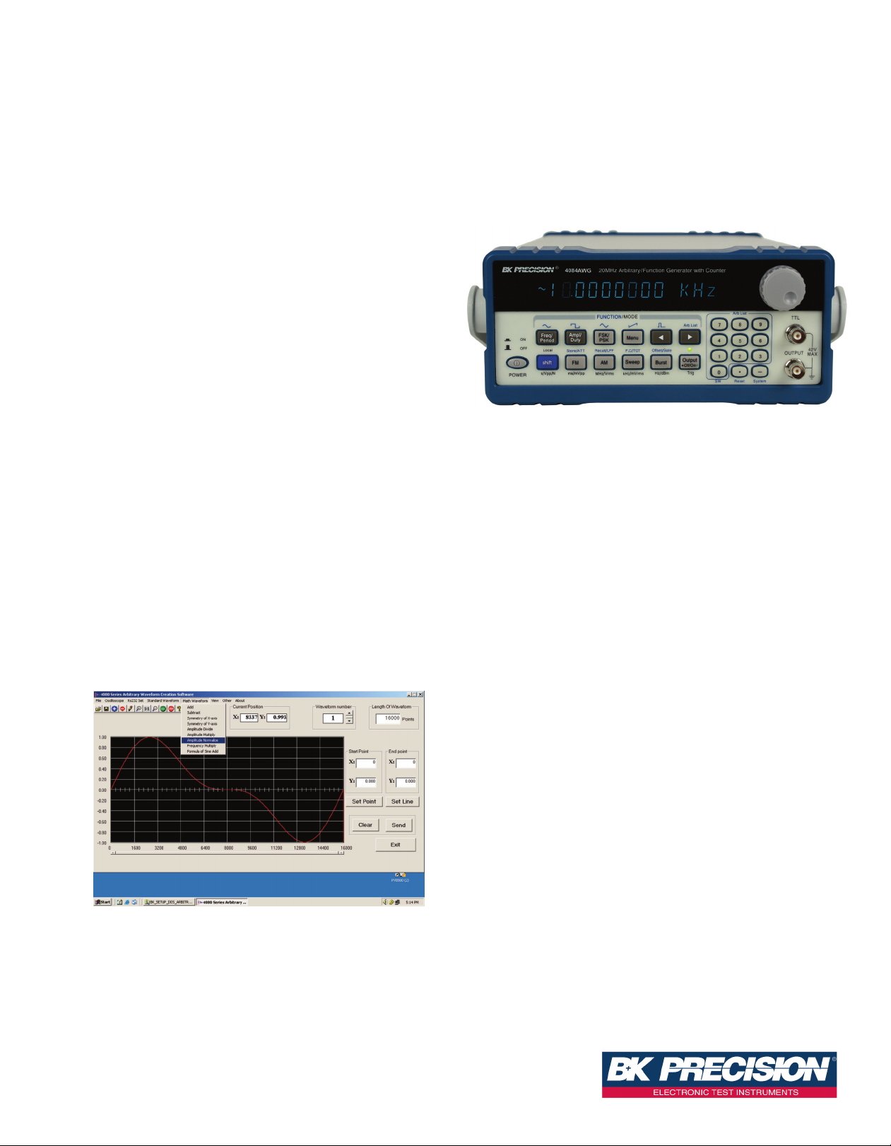
The B&K Precision®4084AWG and 4086AWG are high performance
laboratory grade synthesized function generators with arbitrary capability.
Direct digital synthesis (DDS) techniques are used to create stable,
accurate output signals for all 27 built-in standard and complex (arbitrary)
waveforms. The generators produce high purity, low distortion sine waves
up to 80 MHz, square waves up to 40 MHz and a stable output of very
small signals down to the 1mV - 10mV range. The instrument also provides a built-in 100 MHz Universal Counter with frequency measurement
and totalize function.
Unmatched affordability and excellent performance make models
4084AWG & 4086AWG a perfect fit for many applications in Electronic
Test and Design, Sensor Simulation and Education and Training.
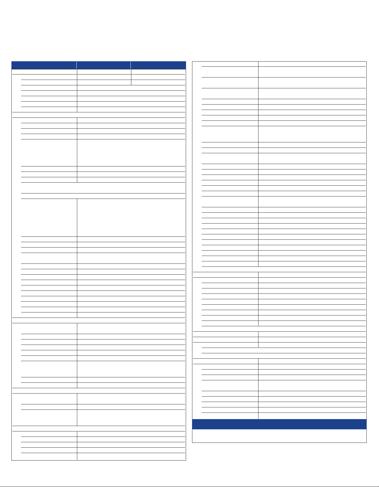
Custom waveform generation made easy
In addition to the built-in complex waveforms, you can use the
4084AWG & 4086AWG to generate custom arbitrary waveforms with
10 bit vertical resolution, 16k memory depth and a sample rate of
200MSa/s. Increase your productivity with the included intuitive Windows
Software: Generate and edit waveforms and download them to the instrument with a single click. Waveforms can be generated in many ways:
Draw waveforms freehand, import them from a text file or start out with
standard functions and customize them with the provided math functions
(Fig. 1).
Additionally, the software provides a direct interface to Tektronix
TDS1000, TDS2000 TPS2000 and TDS3000 series digital storage
oscilloscopes. Users can easily import waveforms originating from the
DSO’s display or internal memory and download and "replay" them on
the instrument.
Versatile modulation and trigger capabilities
The generators provide extensive modulation capabilities including AM,
FM, FSK, PSK, pulse modulation and linear/logarithmic sweep.
Internal and external modulation sources, as well as internal, external
and gated trigger sources are supported. Modulation parameters can
be set precisely and are adjustable over a wide range. For instance,
burst count is programmable in 1 burst increments up to 10000 bursts
and burst phase is adjustable in 0.1º increments.
Convenient user interface and operation
You can adjust parameters via knob or numeric keypad. Enter amplitude values directly in Vpp, mVpp, Vrms, mVrms or dBm, and display
the correct voltage by entering the actual output configuration used
(terminated with 50 Ohm or open circuit). You can enter frequency in
terms of frequency or seconds using time values s, ms, Hz, kHz or
MHz. Submenus are used for modulation modes and other complex
functions. The generators are fully programmable via the standard
RS232 interface, using SCPI commands. The instrument also provides
10 memories to store and recall instrument settings. Additionally the
current state is saved at power off and can be restored at power up.
®
Fig. 1 Arbitrary Waveform Generation Software
Technical data subject to change
© B&K Precision Corp. 2012
ww w.bk prec ision.c o m
Page 2
Arbitrary/Function Generators
Models 4084AWG & 4086AWG
Specifications
Models 4084AWG 4086AWG
Fr e qu enc y C har acte ri sti cs
Sine 1µHz ~ 20MHz 1µHz ~ 80MHz
Square 1µHz ~ 20MHz 1µHz ~ 40MHz
ll Other waveforms 1µHz ~ 100kHz
A
requency Stability ±1x10
F
esolution 1µHz
R
ccuracy ≤ ± 5x10
A
Data entry Units s, ms, Hz, kHz, MHz
Wa vef orm Cha rac ter ist ics
Main Waveforms (Sine, Square)
mplitude resolution 12 bits
A
ample Rate 200MSa/s
S
ine
S
Harmonic Distortion of ≤ - 50dBc (frequency ≤ 5MHz)
Sine Wave* ≤ - 45dBc (frequency ≤ 10MHz)
HD* 0.1% (20Hz ~ 100kHz)
T
quare
S
Rise and fall time* ≤ 15ns
* = Note: Test conditions for harmonic distortion, sine distortion,
rise/fall time Output Amplitude 2Vp-p, Environmental temperature: 25°C±5°C
Others built-in waveforms
7 build-in standard and Sine, Square, Triangle, Positive Ramp, Falling Ramp,
2
omplex waveforms Noise, Pulse, Positive Pulse, Negative Pulse, Positive
c
Waveform Length 4096 dots
Amplitude Resolution 10 bits
Pulse
Duty Cycle 0.1% ~ 99.9% (below 10kHz),
Rise/Fall Time ≤ 100ns (Duty Cycle 20%)
DC signal characteristics
DC range ≤ 10mV – 10V (high impedance)
DC Accuracy ≤ ±5% of setting +10mV (high impedance)
Arbitrary
Non volatile memory 8 waveforms
Waveform length 8~16000 points
Amplitude resolution 10 bits
Frequency range 1µHz~100kHz
Sample rate 200MSa/s
Am pli tu de Ch ar act eri sti cs
Amplitude Range (open circuit) Freq ≤ 40MHz: 2mV ~ 20Vpp , 1mV ~ 10Vpp (50Ω)
Resolution 2µVpp (open circuit), 1µVpp (50Ω)
Accuracy ± 1%+0.2mV (sine wave relative to 1kHz)
Stability ±0.5 % /3 hours
Flatness
For amplitude ≤ 2Vpp ±3% (freq≤ 5MHz), ±10% (5MHz<freq≤ 40MHz)
For amplitude >2Vpp: ±5% (freq≤ 5MHz), ±10% (5MHz<freq≤ 20MHz)
Output Impedance 50Ω
Output Units Vpp, mVpp, Vrms, mVrms, dBm
DC Offset Characteristics
Offset Range (open circuit) Freq ≤ 40MHz: ±10Vpk ac+dc (Offset ≤ 2 x pk to pk amplitude)
Offset Resolution 2µV (open circuit), 1µV (50Ω)
Offset Error ±5% of setting +10mV (Ampl. ≤ 2Vpp into open circuit)
Mo dul ati on
AM Characteristics
Carrier Waveforms Sine or Square
Modulation Source Internal or external
Internal Modulating Waveform Sine, Square, Triangle, Rising/Falling Ramp
Frequency of modulating signal 100µHz ~ 20kHz
D
rectified, Half-wave rectified, Sine transverse cut, Sine
Exponential, Half-round, Sinx/x, Square root, Tangent,
Cardiac, Earthquake, Combination
Freq >40MHz: ±2Vpk ac+dc (Offset ≤ 2 x pk to pk amplitude)
±5% of setting +20mV (Ampl. > 2Vpp into open circuit)
≤ - 40dBc (frequency ≤ 20MHz)
≤ - 35dBc (frequency ≤ 40MHz)
- 30dBc (frequency > 40MHz)
≤
C, Negative DC, Stair wave, Coded Pulse, Full wave
vertical cut, Sine phase modulation, Logarithmic,
1% ~ 99% (10kHz ~ 100kHz)
Freq > 40MHz: 2mV ~ 4Vp-p, 1mV ~ 2Vpp (50Ω)
±1dBm (frequency>40MHz)
6
-
22°C ±5°C)
(
6
-
22°C ±5°C)
(
±20% (frequency>20MHz)
istortion ≤ 2%
D
odulation Depth 1% ~ 120%, 1% ~ 80% (frequency>40MHz,
M
odulation Error ± 5%+0.2% (100µHz < frequency ≤ 10kHz)
M
Max. Amplitude of
ext. input signal 3Vp-p (-1.5V~ +1.5V)
M Characteristics
F
arrier Waveforms Sine or Square
C
odulation Source Internal or external
M
nternal Modulating Waveform Sine, Square, Triangle, Rising/Falling Ramp
I
Frequency of modulating signal 100µHz ~ 10kHz
Deviation Max. 50% of carrier frequency for internal FM
M, with input signal voltage 3Vp-p (-1.5V~+1.5V)
SK Characteristics
F
arrier Waveform Sine or Square
C
Control ModeI Internal or external trigger (external: TTL level,
FSK Rate 0.1ms ~ 800s
PSK Characteristics
arrier Waveform Sine or Square
C
PSK Phase 1 (P1) and Phase 2 (P2), range: 0.0 ~ 360.0°
Resolution 0.1°
PSK rate 0.1ms ~ 800s
ontrol Mode Internal or external trigger (external: TTL level,
C
urst Characteristics
B
Waveform Sine or Square
Burst Counts 1 ~ 10000 cycles
Time interval between bursts 0.1ms ~ 800s
Control Mode Internal, single or external gated trigger
Frequency Sweep Characteristics
Waveform Sine or Square
Sweep Time 1ms ~ 800s (linear), 100ms ~ 800s (log)
Sweep Mode Linear or Logarithmic
Start/ Stop Frequency Same as frequency range of Sine & Square
External trigger signal frequency DC ~ 1kHz (linear) DC~10Hz (log)
Control Mode Internal or external trigger
Inp uts / Outp uts
Main Output
Impedance 50Ω
Protection Short circuit and overload protected
Output MOD OUT
Frequency 100Hz ~ 20kHz
Waveform Sine, Square, Triangle, Rising/Falling Ramp
Amplitude 5Vp-p ± 5%
Output Impedance 600Ω
Modulation IN 3Vpp = 100% Modulation
External Input Trig/FSK/Burst Level - TTL
Un iver sa l Co unt er, Key Spe cs*
Frequency Range
Frequency Measurement 1Hz ~ 100MHz
Totalize mode 50MHz max
* For full specification of the counter section, refer to online manual at www.bkprecision.com
Gen era l
Power Supply 198~242V or 99~121V, Frequency: 47~ 63Hz
Power Consumption <35VA
F
mpl > 2Vpp into open circuit)
A
±10%+2% (10kHz < frequency ≤ 20kHz)
Max 100kHz (carrier frequency≥ 5MHz) for external
low level F1, high level F2)
ow level P1, high level P2)
l
State Storage Memory
Storage Parameters frequency, amplitude, waveform, DC offset values,
Storage Capacity 10 user configurable stored states
Dimensions (W x H x D) 10” x 3.93” x 14.56” (255 mm x 100 mm x 370 mm)
Weight 6.6lbs (3 kg)
Remote Interface RS232
Safety designed according to EN61010
modulation parameters
Three Year Warranty
Included Accessories: BNC to alligator cable, BNC to BNC cable, RS232 communication cable, power line
cord, test report, spare fuse, software installation disk.
2 www.bk prec is io n.c om
v032212
 Loading...