

Page 1

Page 2

Safety Summary
The following safety precautions apply to both operating and maintenance personnel and must be followed during all
phases of operation, service, and repair of this instrument.
Before applying power to this instrument:
• Read and understand the safety and operational information in this manual.
• Apply all the listed safety precautions.
• Verify that the voltage selector at the line power cord input is set to the correct line voltage. Operating the instrument
at an incorrect line voltage will void the warranty.
• Make all connections to the instrument before applying power.
• Do not operate the instrument in ways not specied by this manual or by B&K Precision.
Failure to comply with these precautions or with warnings elsewhere in this manual violates the safety standards of design,
manufacture, and intended use of the instrument. B&K Precision assumes no liability for a customer’s failure to comply
with these requirements.
2
Category rating
The IEC 61010 standard denes safety category ratings that specify the amount of electrical energy available and the
voltage impulses that may occur on electrical conductors associated with these category ratings. The category rating is
a Roman numeral of I, II, III, or IV. This rating is also accompanied by a maximum voltage of the circuit to be tested,
which denes the voltage impulses expected and required insulation clearances. These categories are:
Category I (CAT I): Measurement instruments whose measurement inputs are not intended to be connected to the
mains supply. The voltages in the environment are typically derived from a limited-energy transformer or a battery.
Category II (CAT II): Measurement instruments whose measurement inputs are meant to be connected to the mains
supply at a standard wall outlet or similar sources. Example measurement environments are portable
tools and household appliances.
Category III (CAT III): Measurement instruments whose measurement inputs are meant to be connected to the mains
installation of a building. Examples are measurements inside a building’s circuit breaker panel
or the wiring of permanently-installed motors.
Category IV (CAT IV): Measurement instruments whose measurement inputs are meant to be connected to the primary
power entering a building or other outdoor wiring.
Do not use this instrument in an electrical environment with a higher category rating than what is specied in this manual
for this instrument.
You must ensure that each accessory you use with this instrument has a category rating equal to or higher than the
instrument’s category rating to maintain the instrument’s category rating. Failure to do so will lower the category rating
of the measuring system.
Page 3

Electrical Power
This instrument is intended to be powered from a CATEGORY II mains power environment. The mains power should be
115 V RMS or 230 V RMS. Use only the power cord supplied with the instrument and ensure it is appropriate for your
country of use.
Ground the Instrument
To minimize shock hazard, the instrument chassis and cabinet must be connected to an electrical safety ground. This
instrument is grounded through the ground conductor of the supplied, three-conductor AC line power cable. The power
cable must be plugged into an approved three-conductor electrical outlet. The power jack and mating plug of the power
cable meet IEC safety standards.
Do not alter or defeat the ground connection. Without the safety ground connection, all accessible conductive parts
(including control knobs) may provide an electric shock. Failure to use a properly-grounded approved outlet and the
recommended three-conductor AC line power cable may result in injury or death.
3
Unless otherwise stated, a ground connection on the instrument’s front or rear panel is for a reference of potential only
and is not to be used as a safety ground. Do not operate in an explosive or ammable atmosphere.
Do not operate the instrument in the presence of ammable gases or vapors, fumes, or nely-divided particulates.
The instrument is designed to be used in oce-type indoor environments. Do not operate the instrument
• In the presence of noxious, corrosive, or ammable fumes, gases, vapors, chemicals, or nely-divided particulates.
• In relative humidity conditions outside the instrument’s specications.
• In environments where there is a danger of any liquid being spilled on the instrument or where any liquid can condense
on the instrument.
• In air temperatures exceeding the specied operating temperatures.
• In atmospheric pressures outside the specied altitude limits or where the surrounding gas is not air.
• In environments with restricted cooling air ow, even if the air temperatures are within specications.
• In direct sunlight.
This instrument is intended to be used in an indoor pollution degree 2 environment. The operating temperature range is
0∘C to 40∘C and 20% to 80% relative humidity, with no condensation allowed. Measurements made by this instrument
may be outside specications if the instrument is used in non-oce-type environments. Such environments may include
rapid temperature or humidity changes, sunlight, vibration and/or mechanical shocks, acoustic noise, electrical noise,
strong electric elds, or strong magnetic elds.
Page 4

Do not operate instrument if damaged
If the instrument is damaged, appears to be damaged, or if any liquid, chemical, or other material gets on or inside the
instrument, remove the instrument’s power cord, remove the instrument from service, label it as not to be operated,
and return the instrument to B&K Precision for repair. Notify B&K Precision of the nature of any contamination of the
instrument.
Clean the instrument only as instructed
Do not clean the instrument, its switches, or its terminals with contact cleaners, abrasives, lubricants, solvents, acids/bases,
or other such chemicals. Clean the instrument only with a clean dry lint-free cloth or as instructed in this manual. Not
for critical applications
This instrument is not authorized for use in contact with the human body or for use as a component in a life-support
device or system.
4
Do not touch live circuits
Instrument covers must not be removed by operating personnel. Component replacement and internal adjustments must
be made by qualied service-trained maintenance personnel who are aware of the hazards involved when the instrument’s
covers and shields are removed. Under certain conditions, even with the power cord removed, dangerous voltages may
exist when the covers are removed. To avoid injuries, always disconnect the power cord from the instrument, disconnect
all other connections (for example, test leads, computer interface cables, etc.), discharge all circuits, and verify there
are no hazardous voltages present on any conductors by measurements with a properly-operating voltage-sensing device
before touching any internal parts. Verify the voltage-sensing device is working properly before and after making the
measurements by testing with known-operating voltage sources and test for both DC and AC voltages. Do not attempt
any service or adjustment unless another person capable of rendering rst aid and resuscitation is present.
Do not insert any object into an instrument’s ventilation openings or other openings.
Hazardous voltages may be present in unexpected locations in circuitry being tested when a fault condition in the circuit
exists.
Fuse replacement must be done by qualied service-trained maintenance personnel who are aware of the instrument’s fuse
requirements and safe replacement procedures. Disconnect the instrument from the power line before replacing fuses.
Replace fuses only with new fuses of the fuse types, voltage ratings, and current ratings specied in this manual or on
the back of the instrument. Failure to do so may damage the instrument, lead to a safety hazard, or cause a re. Failure
to use the specied fuses will void the warranty.
Servicing
Page 5

Do not substitute parts that are not approved by B&K Precision or modify this instrument. Return the instrument to
B&K Precision for service and repair to ensure that safety and performance features are maintained.
For continued safe use of the instrument
• Do not place heavy objects on the instrument.
• Do not obstruct cooling air ow to the instrument.
• Do not place a hot soldering iron on the instrument.
• Do not pull the instrument with the power cord, connected probe, or connected test lead.
• Do not move the instrument when a probe is connected to a circuit being tested.
Safety Symbols
Symbol Description
indicates a hazardous situation which, if not avoided, will result in death or serious injury.
5
indicates a hazardous situation which, if not avoided, could result in death or serious injury
indicates a hazardous situation which, if not avoided, will result in minor or moderate injury
Refer to the text near the symbol.
Electric Shock hazard
Alternating current (AC)
Chassis ground
Earth ground
This is the In position of the power switch when instrument is ON.
This is the Out position of the power switch when instrument is OFF.
is used to address practices not related to physical injury.
Page 6

Contents
1 Quick Start 10
1.1 Front Panel 10
1.2 Rear Panel 10
1.3 Touch Screen Display 10
1.4 Waveform Selection and Setup 10
1.5 Create a simple sine wave 11
1.5.1 Frequency and Phase 12
1.5.2 Amplitude, and Oset 12
1.6 To Turn On/O Output 13
1.6.1 Function Keys 13
2 Sine Waveform 14
2.1 Frequency/Period 14
2.2 Amplitude 14
2.3 Oset 15
2.4 Phase 16
2.5 Harmonics 16
2.5.1 Harmonic Type 17
2.5.2 Harmonic Order 18
2.5.3 Harmonic Amplitude 18
2.5.4 Harmonic Phase 18
3 Square Wave 19
3.1 Duty Cycle 19
3.1 Oset, High/Low Levels 19
3.2 Phase 20
4 Ramp Wave 23
4.1 Frequency, Amplitude, Oset, High/Low level, and Phase 23
4.2 Symmetry 24
5 Pulse Wave 27
5.1 Frequency, Amplitude, Oset, High/Low level, and Phase 27
5.2 Pulse Width and DutyCycle 27
5.3 Rising and Falling Edges 28
5.4 Delay 29
6 Noise Wave 32
6.1 Standard Deviation 32
6.2 Mean 33
6.3 Bandwidth 33
7 DC Wave 35
8 Arbitrary Wave 36
8.1 DDS 36
8.2 TrueArb 36
8.2.1 Sampling Rate 37
8.3 Waveform Selection 37
8.4 Selecting a Built-in Waveform 38
8.5 Stored Waveform 38
Page 7

9 Modulation Function 40
9.1 AM 40
9.1.1 To Select Modulation Source 41
9.1.2 Internal Source 41
9.1.3 External Source 41
9.1.4 Modulation Depth 41
9.1.5 Modulation Frequency 41
9.1.5.1 DSB-AM 42
9.1.5.2 FM 42
9.1.5.3 Frequency Deviation 43
9.1.5.4 PM 43
9.1.5.5 Phase Deviation 44
9.1.5.6 FSK 44
9.1.6 Key Frequency 44
9.1.7 Hop Frequency 45
9.1.7.1 ASK 45
9.1.7.2 PSK 46
9.1.7.3 PWM 46
9.1.8 Pulse Width/Duty Deviation 46
10 Sweep Function 49
10.1 Sweep Frequency 49
10.2 Start Frequency and Stop Frequency 49
10.3 Center Frequency and Frequency Span 50
10.4 Sweep Type 50
10.5 Linear Sweep 50
10.6 Log Sweep 50
10.7 Sweep Trigger Source 50
10.8 Internal Trigger 51
10.9 External Trigger 51
10.10 Manual Trigger 51
7
11 Burst Function 52
11.1 Burst Type 52
11.1.1 N-Cycle 52
11.1.2 Innite 53
11.1.3 Gated 53
11.1.4 Start Phase 54
11.1.5 Burst Period 54
11.1.6 Cycles/Innite 54
11.1.7 Delay 54
11.1.8 Burst Trigger Source 55
11.1.9 Internal Trigger 55
11.1.10 External Trigger 55
11.1.11 Manual Trigger 55
12 Storage System 56
12.1 To Store and Recall 56
12.1.1 USB Device (0:) 56
12.1.2 Browse 57
12.1.3 File Type 57
12.1.4 State File 58
12.1.5 Data File 58
12.2 File Operation 58
12.2.1 To Save the Instrument State 58
12.2.2 Select the character 59
12.2.3 Delete the character 59
12.2.4 Save the le. 59
Page 8

12.2.5 To Recall State File or Data File 59
12.2.6 To Delete File 59
12.2.7 To Copy and Paste File 59
13 Utility Function 60
13.1 System Settings 61
13.2 Number Format 62
13.3 Language Setup 62
13.4 Power On 62
13.5 Set to Default 63
13.6 Beep 63
13.7 Screen Saver 63
13.8 System Info 63
13.9 Software Update 63
13.10 Built-in Help 64
13.11 Test/Cal 65
13.11.1 Self Test 65
13.11.2 Screen Test 66
13.11.3 Key Test 66
13.11.4 LED Test 67
13.11.5 Board Test 67
13.11.6 Touch Adjust 67
13.12 Frequency Counter 68
13.12.1 Counter Setup 69
13.13 Parameters to be measured 69
13.14 Reference Frequency 69
13.15 Trigger Level 69
13.16 Coupling Mode 69
13.17 High Frequency Rejection 70
13.18 Output 70
13.19 Load 70
13.19.1 Steps for setting the load: 70
13.20 Polarity 70
13.21 EqPhase 71
13.22 Waveforms Combination Mode 71
13.23 CH Copy/Coupling 71
13.23.1 Channel Coupling 71
13.23.2 Frequency Coupling 72
13.23.3 Amplitude Coupling 73
13.23.4 Phase Coupling 73
13.24 Channel Tracking 74
8
14 Output Synchronization 75
14.1 Sync Signals of Dierent Waveforms 75
14.1.1 Modulated Waveform 75
14.1.2 Sweep and Burst Waveform 75
15 Clock Source 76
15.1 Sync methods for two or more instruments: 76
15.2 Synchronization among multiple instruments 76
16 Channel Phase Mode 77
17 Overvoltage Protection 78
18 Remote Interface 79
18.1 User-dened programming 79
18.2 Remote Control via USB 79
18.3 Remote Control via GPIB 80
18.4 Remote Control via LAN 80
Page 9

19 Specications 81
20 Appendix: Waveforms 82
20.1 Common Waveforms 82
20.1 Math Waveforms 82
20.2 Engine Waveforms 83
20.3 Window Waveforms 84
20.4 Trigonometric Waveforms 85
20.5 Square Waveforms 85
20.6 Medical Waveforms 85
20.7 Modulated Waveforms 86
20.8 Filter Waveforms 86
20.9 Demo Waveforms 87
21 Daily Maintenance 88
21.1 Cleaning 88
22 LIMITED THREE-YEAR WARRANTY 89
23 Service Information 90
9
Page 10

Quick Start
1.1 Front Panel
4060B Series front panel includes a touch screen, menu softkeys, numeric keyboard, knob, function keys, arrow keys, and
channel control area as shown in Figure 1.1.
Item Description
1 Power Switch
2 USB Port (load waveforms, store settings, etc...)
3 Touchscreen
4 Soft Keys
5 Number Pad
6 Function and Channel Keys
7 Knob and Selection Button
8 Arrow Keys
9 Channel Outputs
Figure 1.1 Front Panel View
1.2 Rear Panel
The rear panel shown in Figure 1.2 provides multiple interfaces, including Counter, 10MHz In/Out, Aux In/Out, LAN,
USB Device, Earth Terminal and AC Power Supply Input.
1.3 Touch Screen Display
The screen displays the parameters and a the waveform for a single channel. Most of the elds can be accessed either
through the function keys below the screen or by pressing their value on screen. Figure 1.3 shows a view of Channel
1 with a simple waveform (sine wave). The values and parameters available on-screen change depending on the mode,
options and waveform selected.
1.4 Waveform Selection and Setup
Press the “Waveform” button to open the waveform setup menu shown in Figure 1.4. The softkeys show the available
waveforms for that page. The “Page 1/2” button accesses the other page of waveforms shown in the second image in
Figure 1.4.
Page 11

Quick Start 11
Item Description
1 Power Input
2 USB
3 Ethernet
4 Counter Input
5 Auxillary Input/Output
6 Clock Input/Output (10 MHz)
7 Ground Connection
Figure 1.2 Rear Panel of 4060B Series
Item Description
1 Channel Tab
2 Waveform
3 0 V reference
4 Parameters
5 Output Settings
6 Status indicators (clock, lock and network)
7 Settings menu
Figure 1.3 Touch Screen Display
1.5 Create a simple sine wave
By default, the generator starts congure with a 1 kHz, 4 V peak to peak, symmetric to the ground reference waveform
starting at 0 degrees. All of these parameters are changeable.
Page 12

Quick Start 12
Page 1
Page 2
Figure 1.4 Waveform Menu
1.5.1 Frequency and Phase
To set the frequency, press the rst soft-key, the frequence value to the right of the waveform, or the word “frequency”
above the rst soft-key. The eld, when ready for editing, is highlighted in blue as shown in Figure 1.5. Use the knob,
arrow keys, and the number pad to set the desired frequency. As the value is changed the output will follow the changes
as they occur if the output is on. Phase is modied in the same manner.
Figure 1.5 Frequency Setting
1.5.2 Amplitude, and Oset
Like setting the frequency, select the parameter to modify and use the knob and keys to change its value. The oset and
amplitude are related through the eective maximum and minimum voltages. The waveform output is fully dened by
either setting the amplitude and oset, or the high and low level. The high and low level dene the peak values of the
waveform.
Page 13

Quick Start 13
1.6 To Turn On/O Output
The two keys on the right side of the operation panel above each channel output are used to enable and disable the
output. When enabled, the key will light up. When enabled and lit, pressing the button again disables the respective
channel. Each key can also change the load impedance value by pressing and holding the key for 2 seconds.
Note: Load impedance is only modies the signal voltage setting. HiZ expects an impedance much larger than 50,
so the output voltage is the same as the internal driving source voltage. When set to 50, the displayed voltage is half
of this value. If the wrong setting is chosen, the output voltage can by up to double, or down to half of the expected
value. See Section 13.19 for more.
1.6.1 Function Keys
Access to most of the conguration and machine setup is through the function keys. See Figure 1.6.
Figure 1.6 Function Keys
Mod. This is the waveform “Modulation” setup and enable key. When pressed, the modulation set-
tings are applied to the current waveform. See Section 9 for details.
Sweep This is the waveform “Sweep” frequency setup and enable key. This key also applies sweep set-
tings to the current waveform when pressed. See Section 10 for details.
Burst This is the waveform “Burst” setup and enable key. This key also applies burst settings to the
current waveform when pressed. See Section 11 for details.
Parameter This key returns the menu system to the current waveform parameter settings. This is the menu
set that opens when selecting a “waveform”.
Utility This key opens the main menu for conguring the system settings of the generator. Generator
conguration such as the remote interface, clocking, synchronization, and other functions are accessed in this menu.
Store/Recall The le browser is opened by this key giving access to open, save and manage system setups.
Waveforms The set of waveform types is accessed in this menu.
Ch1/Ch2 This key, when pressed, changes the active waveform menu. See the color of the waveform and
the tab brought to the foreground to verify which channel is selected.
Page 14

Sine Waveform
Press the “Waveforms” key and then press the Sine softkey. The screen shown in Figure 2.1 will open. The parameters
available for sine waveforms include frequency, period, amplitude, high level, low level, oset and phase.
Parameter Description
Frequency/Period Set the signal frequency or period; The current parameter will be switched at a second press.
Amplitude/HighLevel Set the signal amplitude or high level; The current parameter will be switched at a second press.
Oset/LowLevel Set the signal oset or low level; The current parameter will be switched at a second press.
Phase Set the phase of the signal.
Figure 2.1 Sine Wave Parameters
2.1 Frequency/Period
Frequency is one of the most important parameters of basic waveforms. For dierent instrument models and waveforms,
the available ranges of frequency are dierent. For detailed information, please refer to “4060B Series Datasheet”. The
default frequency is 1 kHz.
1. Press Waveforms → Sine → Frequency, to set the frequency parameter. The frequency shown on the screen when the
instrument is powered on is the default value or the set value of last power down. If Period (rather than Frequency) is
the desired parameter, press Frequency/Period again to enter the Period mode. The current value for the waveform’s
period is now displayed in inverse color. Press the Frequency/Period key once again to return to the Frequency entry
mode.
2. Input the desired frequency.
Use the numeric keyboard to input the parameter value directly, and press the corresponding key to select the parameter
unit. Or use the arrow keys to select the digit to edit, and then use the knob to change its value.
Note: When using the numeric keyboard to enter the value, the left arrow key can be used to move the cursor
backward and delete the value of the previous digit.
2.2 Amplitude
The amplitude setting range is limited by the “Load” and “Frequency/Period” settings. For detailed information, please
refer to “4060B Series Datasheet”.
Page 15

Sine Waveform 15
Figure 2.2 Set Frequency
1. Press Waveforms → Sine → Amplitude, to set the amplitude. The amplitude shown on the screen when the instrument
is powered on is the default value or the set value of last power down. If setting the waveform’s high level is desired,
press the Amplitude/HighLevel key again to switch into the high level parameter (the current operation is displayed
in inverse color).
2. Input the desired amplitude.
Use the numeric keyboard to input the parameter value directly, and press the corresponding key to select the parameter
unit. Or use the arrow keys to select the digit to edit, and then use the knob to change its value.
Figure 2.3 Set Amplitude
2.3 Oset
The oset setting range is limited by the “Load” and “Amplitude/HighLevel” settings. For detailed information, please
refer to “4060B Series Datasheet”. The default value is 0Vdc.
1. Press Waveforms → Sine → Oset, to set the oset. The oset shown on the screen when the instrument is powered
on is the default value or the set value of last power down. If you want to set the waveform by low level, press the
Oset/LowLevel key again, to switch into the low level parameter (the current operation is displayed in inverse color).
2. Input the desired oset.
Use the numeric keyboard to input the parameter value directly, and press the corresponding key to select the parameter
unit. Or use the arrow keys to select the digit to edit, and then use the knob to change its value.
Page 16

Sine Waveform 16
Figure 2.4 Set Oset
2.4 Phase
1. Press Waveforms → Sine → Phase, to set the phase. The Phase shown on the screen when the instrument is powered
on is the default value or the set value of last power down.
2. Input the desired phase.
Use the numeric keyboard to input the parameter value directly and press the corresponding key to select the parameter
unit. Or use the arrow keys to select the digit to edit, and then use the knob to change its value.
Figure 2.5 Set Phase
Note When the independent mode is enabled, the phase parameter cannot be modied
2.5 Harmonics
The 4060B Series can be used as a harmonic generator to output harmonics with specied order, amplitude and phase.
According to the Fourier transform, a periodic time domain waveform is the superposition of a series of sine waveforms
as shown in the equation below:
Page 17

Sine Waveform 17
Figure 2.6
Press Waveforms → Sine → Harmonic and choose “On”, then press
Item Description
Type Set the harmonic type to “odd”, “ever” or “all”.
Order Set the order of the harmonic.
Harmonic Ampl Set the amplitude of the harmonic.
Harmonic Phase Set the phase of the harmonic.
Cancel Return to the sine parameters menu.
Figure 2.7 Harmonic Interface
2.5.1 Harmonic Type
The 4060B Series can output odd harmonics, ever harmonics and user-dened orders of harmonics. After entering the
harmonic setting menu, press Type to select the desired harmonic type.
1. Press Even, the instrument will output fundamental waveform and even harmonics.
2. Press Odd, the instrument will output fundamental waveform and odd harmonics.
3. Press All, the instrument will output fundamental waveform and all the user-dened orders of harmonics.
Page 18

Sine Waveform 18
2.5.2 Harmonic Order
After entering the harmonic setting menu, press Order, the use the numeric keyboard or knob to input the desired value.
• The range is limited by the maximum output frequency of the instrument and current fundamental waveform frequency.
• Range: 2 to maximum output frequency of the instrument ÷ current fundamental waveform frequency The maximum
is 10.
2.5.3 Harmonic Amplitude
After entering the harmonic setting menu, press Harmonic Ampl to set the harmonic amplitude of each order.
1. Press Order to select the sequence number of the harmonic to be set.
2. Press Harmonic Ampl to set the amplitude of the harmonic selected. Use the arrow keys and knob to change the
value. Or use the numeric keyboard to input the amplitude value and then select the desired unit from the pop-up
menu. The units available are Vpp, mVpp and dBc.
2.5.4 Harmonic Phase
After entering the harmonic setting menu, press Harmonic Phase to set the harmonic phase of each order.
1. Press Order to select the sequence number of the harmonic to be set.
2. Press Harmonic Phase to set the phase of the harmonic selected. Use the arrow keys and knob to change the value.
Or use the numeric keyboard to input the phase value and then select the unit °.
Page 19

Square Wave
Press Waveforms key to select the waveform function, and press the Square softkey. The square waveform parameters
are set by using the Square operation menu.
The parameters of square waveforms include frequency/period, amplitude/high level, oset/low level, phase and duty. As
shown in Figure 3.1, select DutyCycle. The duty cycle parameter area is highlighted in the parameter display window,
and users can set the duty cycle value here.
Function Description
Frequency/ Period Set the signal frequency or period; The current parameter will be switched at a second press.
Amplitude/ HighLevel Set the signal amplitude or high level; The current parameter will be switched at a second
press.
Oset/ LowLevel Set the signal oset or low level; The current parameter will be switched at a second press.
Phase Set the phase of the signal.
DutyCycle Set the duty cycle for square waveform.
Figure 3.1 Square Wave Parameters
1 Duty Cycle
The ratio of the amount of time the pulse is in the high state and the waveform’s period.
The duty cycle setting range is limited by the “Frequency/Period” setting. For detailed information, please refer to
“4060B Series Datasheet”. The default value is 50%.
1. Press Waveforms → Square → DutyCycle, to set the duty cycle. The duty cycle shown on the screen when the
instrument is powered on is the default value or the set value of last power down.
2. Input the desired Duty Cycle. Use the numeric keyboard to input the parameter value directly and press the corresponding key to select the parameter unit. Or use the arrow keys to select the digit to edit, and then use the knob
to change its value. The generator will change the waveform immediately.
Note: The methods of setting other parameters of square signal are similar to sine waveform function.
3.1 Oset, High/Low Levels
Page 20

Square Wave 20
3.2 Phase
Figure 3.2 Set Duty Cycle
Figure 3.3 Set Duty Cycle
Figure 3.4 Set Oset
Page 21

Square Wave 21
Figure 3.5 Set Hi Level
Figure 3.6 Set Low Level
Figure 3.7 Set Phase
Page 22

Square Wave 22
Figure 3.8 Phase at 180 degrees
Page 23

Ramp Wave
Press Waveforms key to select the waveform function, and press the Ramp softkey. The ramp waveform parameters are
set by using the ramp operation menu.
The parameters for ramp waveforms include frequency/period, amplitude/high level, oset/low level, phase and symmetry.
As shown in Figure 4.1, in the soft key menu, select Symmetry. The symmetry parameter area is highlighted in the
parameter display window, and users can set the symmetry value here.
Figure 4.1 Ramp Waveform Main Screen
Frequency and Period Set the signal frequency or period; The current parameter will be switched at a second press.
Amplitude/ HighLevel Set the signal amplitude or high level; The current parameter will be switched at a second press.
Oset/ LowLevel Set the signal oset or low level; The current parameter will be switched at a second press.
Phase Set the phase of the signal.
Symmetry Set the symmetry for ramp waveform.
4.1 Frequency, Amplitude, Oset, High/Low level, and Phase
Set the frequency, amplitude, high level, low level, oset and phase as shown in Figures 4.2, 4.3, 4.4, 4.5, 4.6.
Figure 4.2 Set Frequency
Page 24

Ramp Wave 24
Figure 4.3 Set Amplitude
Figure 4.4 Set Oset
4.2 Symmetry
The percentage that the rising period takes up the whole Period.
Input Range: 0~100% Default Value: 50%
1. Press Waveforms → Ramp → Symmetry, to set the symmetry. The symmetry shown on the screen when the
instrument is powered on is the default value or the set value of last power down.
2. Input the desired Symmetry.
Use the numeric keyboard to input the parameter value directly, and press the corresponding key to select the parameter
unit. Or use the arrow keys to select the digit to edit, and then use the knob to change its value. The generator will
change the waveform immediately.
Page 25

Ramp Wave 25
Figure 4.5 Set High Level
Figure 4.6 Set Low Level
Figure 4.7 Set Phase
Page 26

Ramp Wave 26
Figure 4.8 Set Symmetry 15%
Figure 4.9 Set Symmetry 90%
Page 27

Pulse Wave
Press Waveforms key to select the waveform function, and press the Pulse softkey. The pulse waveform parameters are
set by using the pulse operation menu.
The parameters for pulse waveforms include frequency/period, amplitude/high level, oset/low level, width, rise/fall and
delay. As shown in Figure 5.1, in the soft key menu, select PulWidth. The pulse width parameter area is highlighted in
the parameter display window, and users can set the pulse width value here.
Figure 5.1 Pulse Waveform Main Screen
Frequency/ Period Set the signal frequency or period; The current parameter will be switched at a second press.
Amplitude/ HighLevel Set the signal amplitude or high level; The current parameter will be switched at a second press.
Oset/ LowLevel Set the signal oset or low level; The current parameter will be switched at a second press.
PulWidth/ DutyCycle Set the signal pulse width or duty cycle; The current parameter will be switched at a second press.
Rise/ Fall Setting the rise edge or fall edge for pulse waveform. The current parameter will be switched at
a second press.
Delay Setting the delay for pulse waveform.
5.1 Frequency, Amplitude, Oset, High/Low level, and Phase
Set the frequency, amplitude, high level, low level, and oset as shown in Figures 4.2, 4.3, 4.4, 4.5, 4.6.
5.2 Pulse Width and DutyCycle
Pulse width is dened as the time from the 50% threshold of a rising edge amplitude to the 50% threshold of the next
falling edge amplitude (as shown in the gure below). The pulse width setting range is limited by the “Minimum Pulse
Width” and “Pulse Period” setting. For detailed information, please refer to “4060B Series Datasheet”. The default
value is 200s.
Pulse duty cycle is dened as the percentage that the pulse width takes up in the whole period. Pulse duty cycle and
pulse width are correlative. Once a parameter is changed, the other will be automatically changed.
1. Press Waveforms→ Pulse → PulWidth, to set the pulse width. The pulse width shown on the screen when the
instrument is powered on is the default value or the set value of last power down. If you want to set the waveform by
duty, press the PulWidth/DutyCycle key again, to switch into the duty parameter (the current operation is displayed
in inverse color).
Page 28

Pulse Wave 28
Figure 5.2 Set Frequency
Figure 5.3 Set Amplitude
2. Input the desired Pulse Width.
Use the numeric keyboard to input the parameter value directly, and press the corresponding key to select the parameter
unit. Or use the arrow keys to select the digit to edit, and then use the knob to change its value. The generator will
change the waveform immediately.
5.3 Rising and Falling Edges
Rise edge time is dened as the duration of the pulse amplitude rising from 10% to 90% threshold, while fall edge time is
dened as duration of the pulse amplitude moving down from 90% to 10% threshold. The setting of rise/fall edge time
is limited by the currently specied pulse width limit. Users can set rise edge and fall edge independently.
1. Press Waveforms → Pulse → Rise to set the rise edge.
The rise edge shown on the screen when the instrument is powered on is the default value or the set value of last
power down. If you want to set the waveform by fall edge, press the Rise/Fall key again, to switch into the fall edge
parameter (the current operation is displayed in inverse color).
2. Input the desired rise edge.
Use the numeric keyboard to input the parameter value directly, and press the corresponding key to select the parameter
unit. Or use the arrow keys to select the digit to edit, and then use the knob to change its value. The generator will
change the waveform immediately.
Page 29

Pulse Wave 29
5.4 Delay
Figure 5.4 Set Oset
Figure 5.5 Set High Level
Figure 5.6 Set Low Level
Page 30

Pulse Wave 30
Figure 5.7 Set Pulse Width
Figure 5.8 Set Duty Cycle
Figure 5.9 Setting the Risng Edge
Page 31

Pulse Wave 31
Figure 5.10 Pulse Delay
Page 32

Noise Wave
Press Waveforms key to select the waveform function, and press the Noise softkey. The noise parameters are set by using
the noise operation menu.
The parameters for noise include stdev, mean and bandwidth. As shown in Figure 6.1, in the soft key menu, select
Stdev, The stdev parameter area is highlighted in the parameter display window, and users can set the stdev value here.
Noise is non-periodic signal which has no frequency or period.
BandSet Turn on/o the bandwidth setting.
Stdev Setting the stdev for noise waveform.
Mean Setting the mean for noise waveform.
Bandwidth Setting the bandwidth for noise waveform.
6.1 Standard Deviation
Figure 6.1 Noise Parameters Display Interface
Figure 6.2 Setting the Stdev
1. Press Waveforms → Noise → Stdev, to set the stdev. The stdev shown on the screen when the instrument is powered
on is the default value or the set value of last power down.
Page 33

Noise Wave 33
2. Input the desired stdev.
Use the numeric keyboard to input the parameter value directly, and press the corresponding key to select the parameter
unit. Or use the arrow keys to select the digit to edit, and then use the knob to change its value.
6.2 Mean
Figure 6.3 Setting the Mean
1. Press Waveforms → Noise → Mean, to set the mean.
The mean shown on the screen when the instrument is powered on is the default value or the set value of last power
down.
2. Input the desired mean.
Use the numeric keyboard to input the parameter value directly, and press the corresponding key to select the parameter
unit. Or use the arrow keys to select the digit to edit, and then use the knob to change its value.
6.3 Bandwidth
Figure 6.4 Setting the Bandwidth
Page 34

Noise Wave 34
Figure 6.5 Setting the Bandwidth
1. Press Waveforms → Noise → BandSet and choose “On” to set the bandwidth.
The bandwidth shown on the screen when the instrument is powered on is the default value or the set value of last
power on. When changing the function, if the current value is valid for the new waveform, it will be used sequentially.
2. Input the desired bandwidth.
Use the numeric keyboard to input the parameter value directly, and press the corresponding key to select the parameter
unit. Or you can use the arrow keys to select the digit you want to edit, and then use the knob to change its value.
Page 35

DC Wave
Press Waveforms → Page 1/2 → DC, to enter the following interface. Please note that there is a ‘DC oset’ parameter
at the middle of the screen.
Figure 7.1 DC Setting Interface
Page 36
Arbitrary Wave
The Arb signal consists of two types: the system’s built-in waveforms and the user-dened waveforms. Built-in waveforms
are stored in the internal non-volatile memory. Users may also edit the arbitrary waveform with 8 to 8M data points,
namely 8pts to 8Mpts.
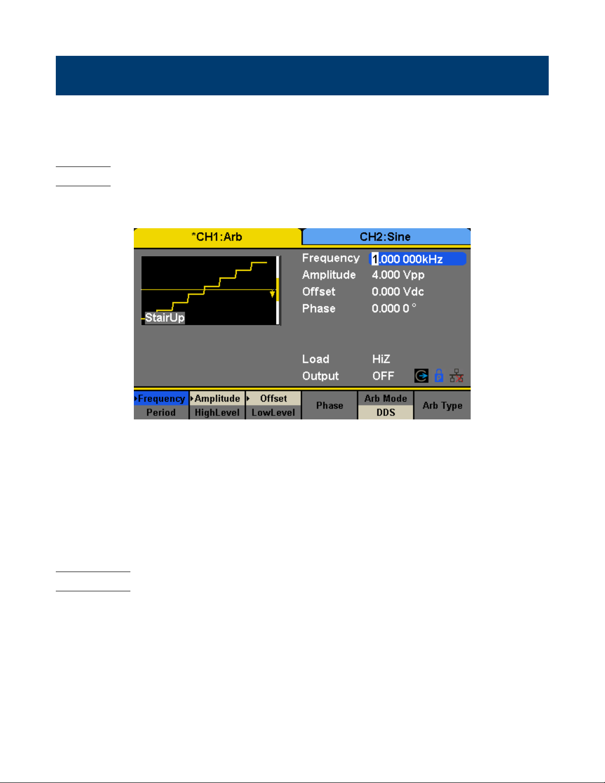
8.1 DDS
Choose Waveforms →Page 1/2 →Arb →Arb Mode and select the “DDS” output mode. The parameters include frequency/period, amplitude/high level, oset/low level and phase.
Figure 8.1 DDS
Frequency/Period Set the signal frequency or period; The current parameter will be switched at a second press.
Amplitude/HighLevel Set the signal amplitude or high level; The current parameter will be switched at a second press.
Oset/LowLevel Set the signal oset or low level; The current parameter will be switched at a second press.
Phase Set the phase of the signal.
In DDS output mode, users can set the frequency or period of the arbitrary waveform. The instrument outputs an
arbitrary waveform which is made up of certain points according to the current frequency
8.2 TrueArb
Choose Waveforms →Page 1/2 →Arb →Arb Mode and select the “TrueArb” output mode. The parameters include
sampling rate/frequency, amplitude/high level, oset/ low level and phase.
SRate/ Frequency Set the signal sampling rate or frequency; The current parameter will be switched at a second
press.
Amplitude/ HighLevel Set the signal amplitude or high level; The current parameter will be switched at a second press.
Oset/ LowLevel Set the signal oset or low level; The current parameter will be switched at a second press.
Phase Set the phase of the signal.
In TrueArb output mode, users can set the sampling rate (the output points per second) or frequency of the arbitrary
waveform. The instrument outputs an arbitrary waveform point by point according to the current sampling rate.
Page 37

Arbitrary Wave 37
Figure 8.2 TrueArb
8.2.1 Sampling Rate
1. Press Waveforms →Page 1/2 →Arb →TureArb →Srate, to set the sampling rate parameter.
The sampling rate shown on the screen when the instrument is powered on is the default value or the set value of last
power on. When setting the function, if the current value is valid for the new waveform, it will be used sequentially.
If you want to set the frequency for the waveform, press SRate/Frequency key again, to switch to the frequency
parameter (the current operation is displayed in inverse color).
2. Input the desired sampling rate.
Use the numeric keyboard to input the parameter value directly, and press the corresponding key to select the parameter
unit. Or you can use the arrow keys to select the digit you want to edit, and then use the knob to change its value.
Figure 8.3 Set the Sampling Rate
Note: The methods of setting the parameters of arbitrary signal are similar to sine waveform function.
8.3 Waveform Selection
There are numerous built-in Arbitrary Waveforms and there is storage for user-dened Arbitrary Waveforms inside the
generator.
Page 38

Arbitrary Wave 38
8.4 Selecting a Built-in Waveform
Choose Waveforms →Page 1/2 →Arb →Arb Type →Built-In to enter the following interface, as shown in Figure 8.4.
See Chapter 20 for the set of available built-in waveforms.
Figure 8.4 Built-in Arbitrary Waveforms
Press Common, Math, Engine, Window, Trigo or other menus to switch to the desired category (the selected category in
the menu bar is highlighted), then rotate the knob or click the touch screen to choose the desired waveform (the selected
waveform is highlighted). Select Accept or press the knob to recall the corresponding waveform.
8.5 Stored Waveform
Choose Waveforms →Page 1/2 →Arb →Arb Type →Stored Waveforms to enter the following interface, as shown in
Figures 8.5, 8.6.
Figure 8.5 Stored Waveform Display Interface
Rotate the knob or touch the screen to choose the desired waveform. Then select Recall or press the knob to recall the
corresponding waveform.
Page 39
Arbitrary Wave 39
Figure 8.6 Stored Waveform Display Interface
Page 40

Modulation Function
Use the Mod key to generate modulated waveforms. The 4060B Series can generate AM, FM, ASK, FSK, PSK, PM,
PWM and DSB-AM modulated waveforms. Modulating parameters vary with the types of the modulation. In AM,
users can set the source (internal/external), depth, modulating frequency, modulating waveform and carrier. In DSBAM, users can set the source (internal/external), modulating frequency, modulating waveform and carrier. In FM, users
can set the source (internal/external), modulating frequency, frequency deviation, modulating waveform and carrier.
In PM, users can set the source (internal/external), phase deviation, modulating frequency, modulating waveform and
carrier. In ASK, users can set the source (internal/external), key frequency and carrier. In FSK, users can set the source
(internal/external), key frequency, hop frequency and carrier. In PSK, users can set the source (internal/external), key
frequency, polarity and carrier. In PWM, users can set the source (internal/external), modulating frequency, width/duty
cycle deviation, modulating waveform and carrier.
We will introduce how to set these parameters in details according to the modulation types.
9.1 AM
The modulated waveform consists of two parts: the carrier and the modulating waveform. In AM, the amplitude of the
carrier varies with the instantaneous voltage of the modulating waveform.
Press Mod → Type → AM, the parameters of AM modulation are shown in Figure 9.1.
Function Explanation
Type AM Amplitude modulation
Source Internal The source is internal
External The source is external. Use the [Aux In/Out] connector at the rear panel.
AM Depth Set the modulation depth.
Shape Sine Choose the modulating waveform.
Square
Triangle
UpRamp
DnRamp
Noise
Arb
AM Freq Set the modulating waveform frequency. Frequency range: 1mHz~1MHz (internal source
only).
Figure 9.1 Setting Interface of AM Modulation
Page 41

Modulation Function 41
9.1.1 To Select Modulation Source
The 4060B Series can accept modulating signal from an internal or external modulation source. Press Mod → AM →
Source to select “Internal” or “External” modulation source. The default is “Internal”.
9.1.2 Internal Source
When internal AM modulation source is selected, press Shape to select Sine, Square, Triangle, UpRamp, DnRamp, Noise
or Arb as modulating waveform.
• Square: 50% duty cycle
• Triangle: 50% symmetry
• UpRamp: 100% symmetry
• DnRamp: 0% symmetry
• Arb: the arbitrary waveform selected of the current channel
Note: Noise can be used as modulating waveform but cannot be used as the carrier.
9.1.3 External Source
When external AM modulation source is selected, the generator accepts external modulating signal from the [Aux In/Out]
connector at the rear panel. At this time, the amplitude of the modulated waveform is controlled by the signal level
applied to the connector. For example, if the modulation depth is set to 100%, the output amplitude will be the maximum
when the modulating signal is +6V and the minimum when the modulating signal is -6V.
The 4060B Series can use one channel as a modulating source for the other channel. The following example takes the
output signal of CH2 as the modulating waveform.
1. Connect the CH2 output terminal to [Aux In/Out] connector on the rear panel using a dual BNC cable.
2. Select CH1 and press Mod to select the desired modulation type as well as set the corresponding parameters, and
then select external modulation source.
3. Select CH2 and select the desired modulating waveform and set the corresponding parameters.
4. Press Output to enable the output of CH1.
9.1.4 Modulation Depth
Modulation depth expressed as a percentage indicates the amplitude variation degree. AM modulation depth varies from
1% to 120%. Press AM Depth to set the parameter.
• In the 0% modulation, the output amplitude is the half of the carrier’s amplitude.
• In the 120 modulation, the output amplitude is the same with the carrier’s amplitude.
• For an external source, the depth of AM is controlled by the voltage level on the connector connected to the [Aux
In/Out]. ±6V correspond to 100% depth.
• When external modulation source is selected, this menu is hidden.
9.1.5 Modulation Frequency
When internal modulation source is selected, press AM Freq to highlight the parameter, then use the numeric keyboard
or arrow keys and knob to input the desired value.
Page 42

Modulation Function 42
• The modulation frequency ranges from 1mHz to 1MHz.
• When external modulation source is selected, this menu is hidden.
9.1.5.1 DSB-AM
DSB-AM is an abbreviation for Double-Sideband Suppressed Carrier –
Amplitude Modulation. Press Mod → Type → DSB-AM. The parameters of DSB-AM modulation are shown in Fig-
ure 9.2.
Function Description
Type DSB-AM DSB Amplitude modulation.
Source Internal The source is internal.
External The source is external. Use the [Aux In/Out] connector at the rear panel.
DSB Freq Set the modulating waveform frequency. Frequency range: 1mHz~1MHz (internal source
only).
Shape Sine Choose the modulating waveform.
Square
Triangle
UpRamp
DnRamp
Noise
Arb
Figure 9.2 Setting Interface of DSB-AM Modulation
Note: The methods of setting the parameters of DSB-AM are similar to AM.
9.1.5.2 FM
The modulated waveform consists of two parts: the carrier and the modulating waveform. In FM, the frequency of the
carrier varies with the instantaneous voltage of the modulating waveform.
Press Mod → Type → FM, the parameters of FM modulation are shown in Figure 9.3.
Page 43

Modulation Function 43
Function Explanation
Type FM Frequency modulation
Source Internal The source is internal
External The source is external. Use the [Aux In/Out] connector at the rear panel.
Freq Dev Set the frequency deviation
Shape Sine Choose the modulating waveform.
Square
Triangle
UpRamp
DnRamp
Noise
Arb
FM Freq Set the modulating waveform frequency. Frequency range 1mHz~1MHz (internal source).
Figure 9.3 Setting Interface of FM Modulation
9.1.5.3 Frequency Deviation
Press FM Dev to highlight the parameter, and then use the numeric keyboard or arrow keys and knob to input the desired
value.
• The deviation should be equal to or less than the carrier frequency.
• The sum of the deviation and the carrier frequency should be equal to or less than maximum frequency of the selected
carrier waveform.
Note: The methods of setting other parameters of FM are similar to AM.
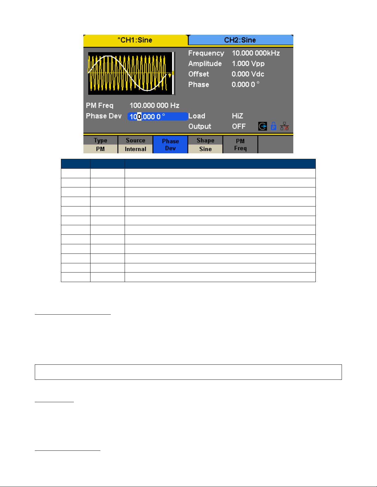
9.1.5.4 PM
The modulated waveform consists of two parts: the carrier and the modulating waveform. In PM, the phase of the carrier
varies with the instantaneous voltage level of the modulating waveform.
Press Mod → Type → PM, the parameters of PM modulation are shown in Figure 9.4.
Page 44
Modulation Function 44
Function Explanation
Type PM Phase modulation
Source Internal The source is internal
External The source is external. Use the [Aux In/Out] connector at the rear panel.
Phase Dev Phase deviation ranges from 0° ~ 360°.
Shape Sine Choose the modulating waveform.
Square
Triangle
UpRamp
DnRamp
Noise
Arb
PM Freq Set the modulating waveform frequency. Frequency range: 1mHz~1MHz.
Figure 9.4 Setting Interface of PM Modulation
9.1.5.5 Phase Deviation
Press Phase Dev to highlight the parameter, and then use the numeric keyboard or arrow keys and knob to input the
desired value.
• Use the numeric keyboard or arrow keys and knob to input the desired value.
• The range of phase deviation is from 0° to 360° and the default value is 100°.
Note: The methods of setting other parameters of PM are similar to AM.
9.1.5.6 FSK
The FSK is Frequency Shift Keying, the output frequency of which switches between two preset frequencies (carrier
frequency and the hop frequency or sometimes known as mark frequency (1) and space frequency (0)).
Press Mod → Type → FSK, the parameters of FSK modulation are shown in Figure 9.5.
9.1.6 Key Frequency
When internal modulation source is selected, press Key Freq to set the rate at which the output frequency shifts between
“carrier frequency” and “hop frequency”.
Page 45

Modulation Function 45
Function Explanation
Type FSK Frequency shift keying modulation.
Source Internal The source is internal.
External The source is external. Use the [Aux In/Out] connector at the rear panel.
Key Freq Set the frequency at which the output frequency shifts between the carrier frequency and the
hop frequency (internal modulation only): 1mHz~1MHz.
Hop Freq Set the hop frequency.
Figure 9.5 Setting Interface of FSK Modulation
• Use the numeric keyboard or arrow keys and knob to input the desired value.
• The key frequency ranges from 1mHz to 1MHz.
• When external modulation source is selected, this menu is hidden.
9.1.7 Hop Frequency
The range of the hop frequency depends on the carrier frequency currently selected. Press Hop Freq to highlight the
parameter, and then use the numeric keyboard or arrow keys and knob to input the desired value.
• Sine: 1uHz~120MHz
• Square: 1uHz~25MHz
• Ramp: 1uHz~1MHz
• Arb: 1uHz~20MHz
Note: The methods of setting other parameters of FSK are similar to AM. In addition, the external modulating signal
of FSK must be Square which complies with the CMOS level specication.
9.1.7.1 ASK
When using ASK (Amplitude Shift Keying), the carrier frequency and key frequency will need to be set. The key frequency
is the shift rate of modulated waveform amplitude.
Press Mod → Type → ASK, the parameters of ASK modulation are shown in Figure 9.6.
Page 46

Modulation Function 46
Function Explanation
Type ASK Amplitude shift keying modulation.
Source Internal The source is internal.
External The source is external. Use the [Aux In/Out] connector at the rear panel.
Key Freq Set the frequency at which the output amplitude shifts between the carrier amplitude and zero
(internal modulation only): 1mHz~1MHz.
Figure 9.6 Setting Interface of ASK Modulation
Note: The methods for setting the parameters of ASK are similar to AM. In addition, the external modulating signal
of ASK must be Square which complies with the CMOS level specication.
9.1.7.2 PSK
When using PSK (Phase Shift Keying), congure the generator to “shift” its output phase between two preset phase
values (carrier phase and modulating phase). The default modulating phase is 180°.
Press Mod → Type → PSK, the parameters of PSK modulation are shown in Figure 9.7.
Note: The methods of setting the parameters of PSK are similar to AM. In addition, the external modulating signal
of PSK must be Square which complies with the CMOS level specication.
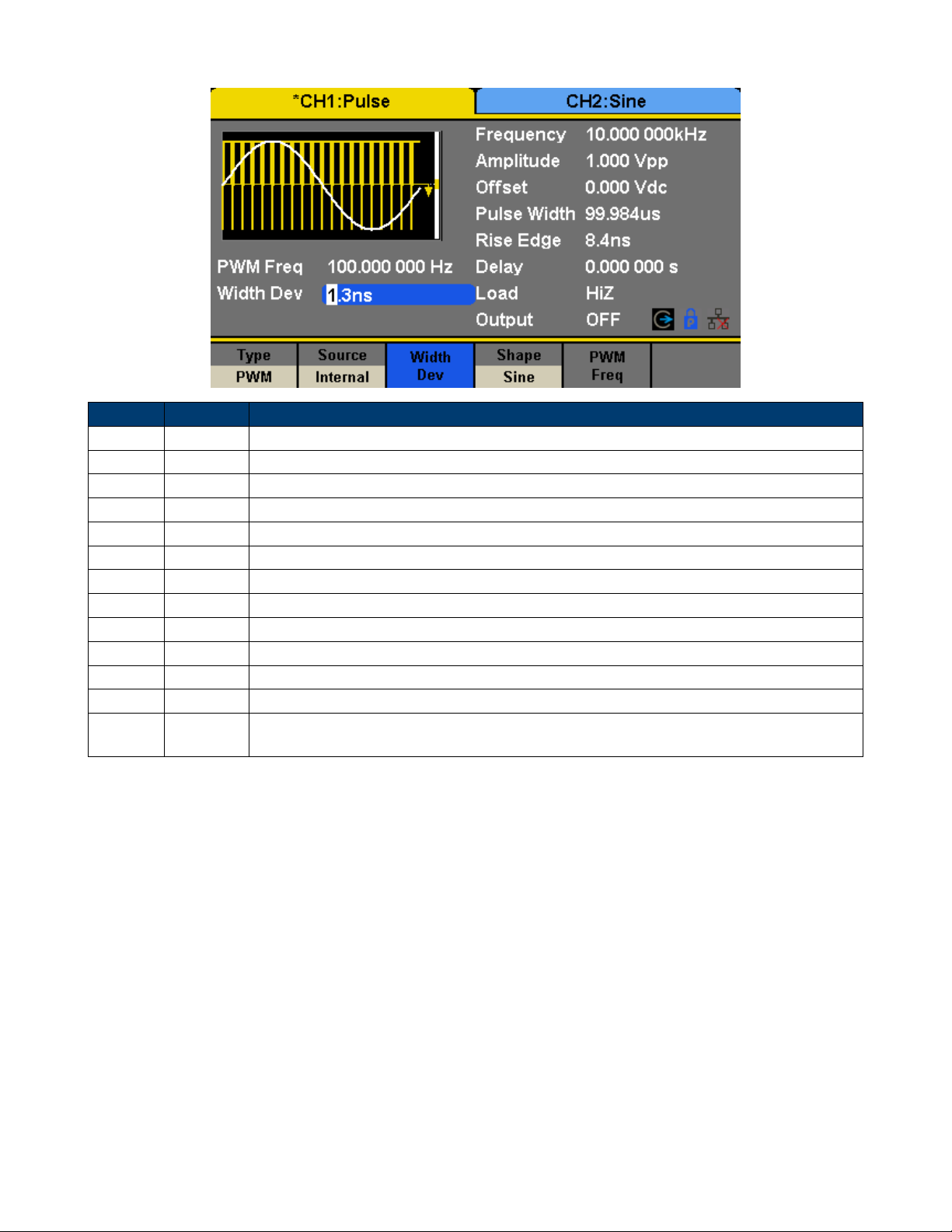
9.1.7.3 PWM
For only the “Pulse” a PWM (Pulse Width Modulation) is available. The pulse width of the pulse varies with the voltage
of the modulating waveform. Especially when using an ARB waveform for modulation, a wide range of waveforms is
possible.
Press Waveforms → Pulse → Mod, the parameters of PWM modulation are shown in Figure 9.8.
9.1.8 Pulse Width/Duty Deviation
Width Deviation represents the variation of the modulated waveform pulse width relative to the original pulse width.
Press Width Dev to highlight the parameter, and use the numeric keyboard or arrow keys and knob to input the desired
value.
• The width deviation cannot exceed the current pulse width.
• The width deviation is limited by the minimum pulse width and current edge time setting.
Page 47

Modulation Function 47
Function Explanation
Type PSK Phase shift keying modulation.
Source Internal The source is internal.
External The source is external. Use the [Aux In/Out] connector at the rear panel.
Key Freq Set the frequency at which the output phase shifts between the carrier phase and 180°
(internal modulation only): 1mHz~1MHz.
Polarity Positive Set the modulating polarity.
Negative
Figure 9.7 Setting Interface of PSK Modulation
Duty Deviation represents the variation (%) of the modulated waveform duty relative to the original duty. Press Duty
Dev to highlight the parameter, and then use the numeric keyboard or arrow keys and knob to input the desired value,
as shown in the Figure 2-33.
• The duty deviation cannot exceed the current pulse duty cycle.
• The duty deviation is limited by the minimum duty cycle and current edge time setting.
• Duty deviation and width deviation are correlative. Once a parameter is changed, the other will be automatically
changed.
Note: The methods of setting other parameters of PWM are similar to AM.
Page 48
Modulation Function 48
Function Description
Type PWM Pulse width modulation. The carrier is pulse.
Source Internal The source is internal.
External The source is external. Use the [Aux In/Out] connector at the rear panel.
Width Dev Set the width deviation.
Duty Dev Set the duty deviation.
Shape Sine Choose the modulating waveform.
Square
Triangle
UpRamp
DnRamp
Noise
Arb
PWM Freq Set the modulating waveform frequency. Frequency range: 1mHz~1MHz (internal source
only).
Figure 9.8 Setting Interface of PWM Modulation
Page 49
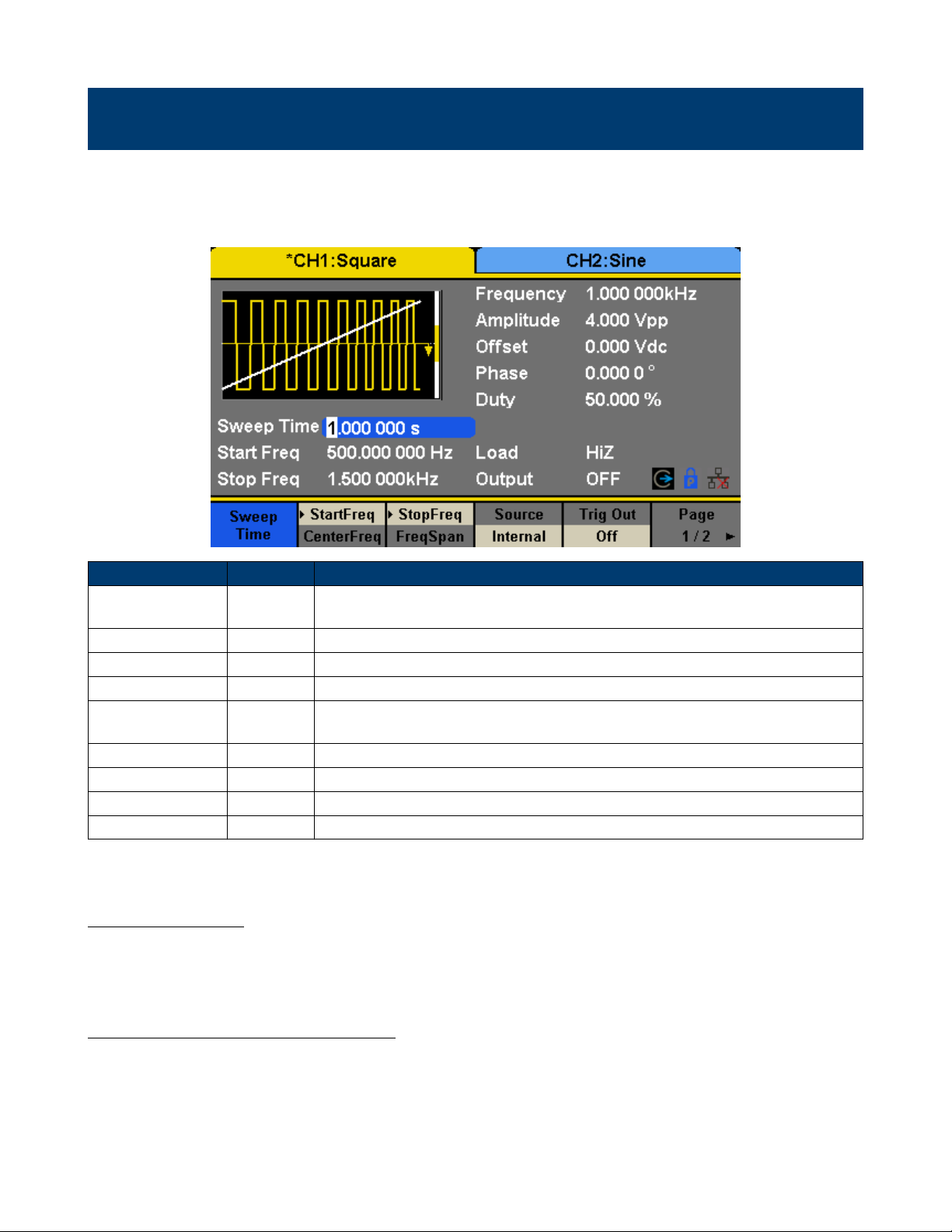
Sweep Function
In the sweep mode, the generator steps from the start frequency to the stop frequency in the sweep time specied by the
user. The waveforms that support sweep include sine, square, ramp and arbitrary.
Press Sweep key to enter the following menu. Set the waveform parameters by using the operation menu.
Function Explanation
Sweep time Set the time span of the sweep in which the frequency changes from the start
frequency to stop frequency.
Start Freq Mid Freq Set the start frequency of the sweep; Set the center frequency of the sweep.
Stop Freq Freq Span Set the stop frequency of the sweep; Set the frequency span of the sweep.
Source Internal Choose internal source as a trigger.
External Choose external source as a trigger. Use the [Aux In/Out] connector at the rear
panel.
Manual Trigger a sweep by manual.
Trig Out O Disable trigger out.
On Enable trigger out.
Page 1/2 Enter the next page.
Figure 10.1 Sweep Screen (Page 1/2)
1 Sweep Frequency
Use start freq and stop freq or center freq and freq span to set the range of the frequency sweep. Press the key again to
switch between the two sweep range modes.
2 Start Frequency and Stop Frequency
Start Frequency and Stop Frequency are the lower and upper limits of the frequency for sweep. Start Frequency Stop
Frequency.
• Choose Direction → Up, the generator will sweep from Start frequency to Stop frequency.
• Choose Direction → Down, the generator will sweep from Stop frequency to Start frequency.
Page 50

Sweep Function 50
Function Explanation
Type Linear Set the sweep with linear prole.
Log Set the sweep with logarithmic prole.
Direction Up Sweep upward.
Down Sweep downward.
Page 2/2 Return to the previous page.
Figure 10.2 Setting Interface of Sweep (Page 2/2)
3 Center Frequency and Frequency Span
Center Frequency = (|Start Frequency + Stop Frequency|)/2
Frequency Span = Stop Frequency – Start Frequency
4 Sweep Type
4060B Series provides “Linear” and “Log” sweep proles and the default is “Linear”.
5 Linear Sweep
In linear sweep, the output frequency of the instrument varies linearly in the way of “a number of Hertz per second”.
Choose Sweep → Page 1/2 → Type → Linear, there is a straight line displayed on the waveform on the screen, indicating
that the output frequency varies linearly.
6 Log Sweep
In log sweep, the output frequency of the instrument varies in a logarithmic fashion, that is, the output frequency changes
in the way of “decade per second”. Choose Sweep → Page 1/2 → Type → Log, there is an exponential function curve
displayed on the waveform on the screen, indicating that the output frequency changes in a logarithmic mode.
7 Sweep Trigger Source
The sweep trigger source can be internal, external or manual. The generator will generate a sweep output when a trigger
signal is received and then wait for the next trigger source.
Page 51

Sweep Function 51
Figure 10.3 Linear Sweep Interface
Figure 10.4 Log Sweep Interface
8 Internal Trigger
Choose Source → Internal, the generator outputs continuous sweep waveform when internal trigger is selected. The
default is “Internal”. Choose Trig Out → On, the [Aux In/Out] connector at the rear panel will output the trigger signal.
9 External Trigger
Choose Source → External, the generator accepts the trigger signal inputted from the [Aux In/Out] connector at the
rear panel when external trigger is selected. A sweep will be generated once the connector receives a CMOS pulse with
specied polarity. To set the CMOS pulse polarity, choose Edge to select “Up” or “Down”.
10 Manual Trigger
Choose Source → Manual, a sweep will be generated from the corresponding channel when the Trigger softkey is pressed
when manual trigger is selected. Choose Trig Out → On, the [Aux In/Out] connector at the rear panel will output the
trigger signal.
Page 52

Burst Function
The Burst function can generate versatile waveforms in n this mode. Burst times can last a specic number of waveform
cycles (N-Cycle mode), or when an external gated signals (Gated mode) is applied. Any waveform (except DC) may be
used as the carrier, but noise can only be used in Gated mode.
11.1 Burst Type
4060B Series provides three burst types including N-Cycle, Innite and Gated.
The default is N-Cycle.
Burst Type Trigger Source Carrier
N-Cycle Internal/External/ Manual Sine, Square, Ramp, Pulse, Arbitrary.
Innite External/Manual Sine, Square, Ramp, Pulse, Arbitrary.
Gated Internal/External Sine, Square, Ramp, Pulse, Noise, Arbitrary.
Table 11.1 2-20 Relations among burst type, trigger source and carrier
11.1.1 N-Cycle
In N-Cycle mode, the generator will output waveform with a specied number of cycles after receiving the trigger signal.
Waveforms that support N-Cycle burst include sine, square, ramp, pulse and arbitrary.
Press Burst → NCycle → Cycles, and use the numeric keyboard or arrow keys and knob to input the desired cycles. Set
the waveform parameters by using the operation menu, as shown in Figure 2-38 and Figure 2-39.
Function Explanation
NCycle Use the N-Cycle mode.
Cycles Innite Set the number of the bursts in N-Cycle. Set the number of the bursts in N-Cycle to be
innite.
Start Phase Set the start phase of the burst.
Burst Period Set the burst period.
Source Internal Choose internal source as a trigger.
External Choose external source as a trigger. Use the [Aux In/Out] connector at the rear panel.
Manual Trigger a burst by manual.
Page 1/2 Enter the next page.
Figure 11.1 N-Cycle Burst Interface (Page 1/2)
Page 53

Burst Function 53
Function Explanation
Delay Set the delay time before the burst starts.
Trig Out O Disable trigger out.
On Enable trigger out.
Page 2/2 Return to the previous page.
Figure 11.2 N-Cycle Burst Interface (Page 2/2)
11.1.2 Innite
In innite mode, the cycle number of the waveform is set as an innite value.
The generator outputs a continuous waveform after receiving the trigger signal. Waveforms that support innite mode
include sine, square, ramp, pulse and arbitrary.
Press Burst → NCycle → Innite, and set the trigger source to “external” or
“manual”. The screen will display an innite cycle burst, as shown in Figure 11.3.
Figure 11.3 Innite Burst Interface
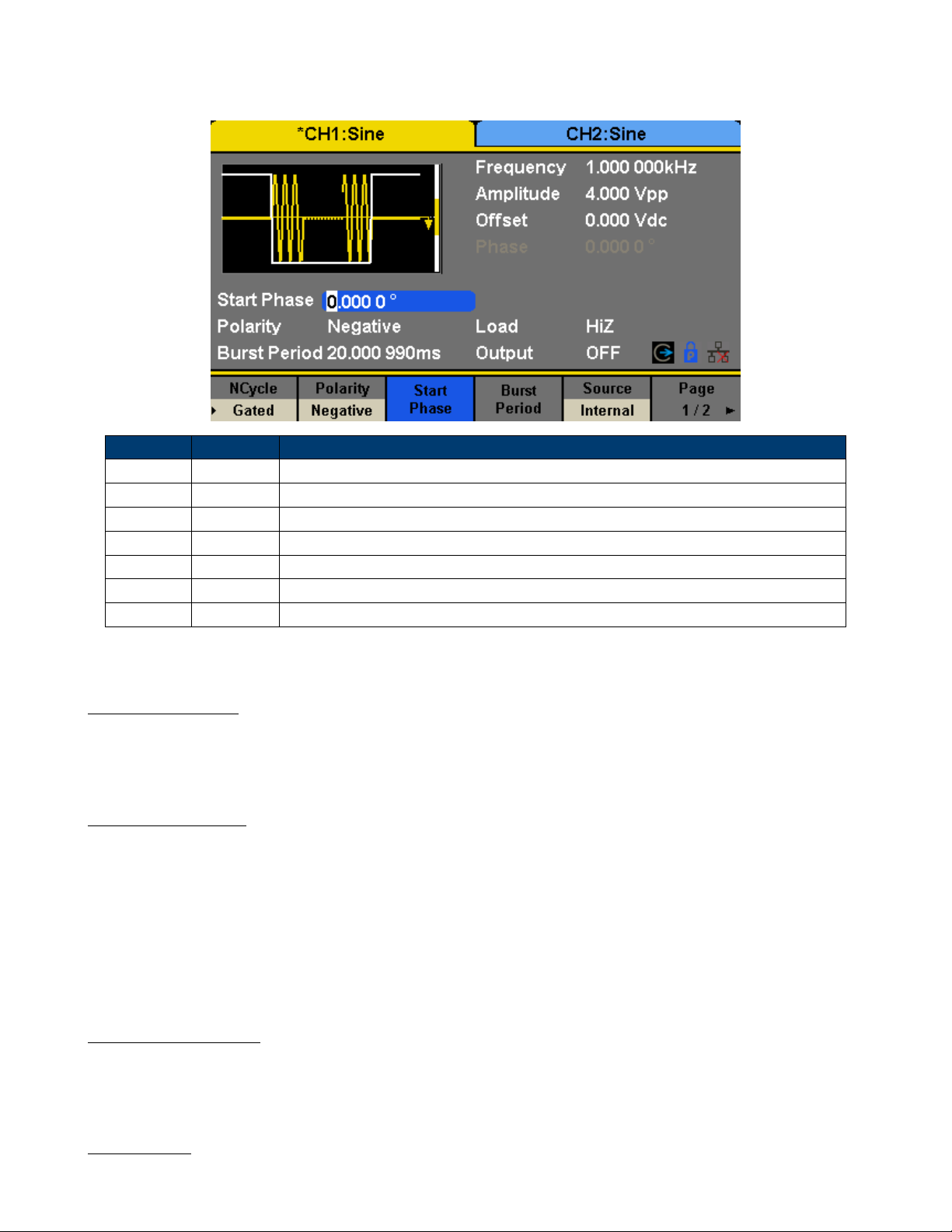
11.1.3 Gated
In gated mode, the generator controls the waveform output according to the gate signal level. When the gated signal
is “true”, the generator outputs a continuous waveform. When the gated signal is “false”, the generator rst completes
the output of the current period and then stops. Waveforms that support gated burst include sine, square, ramp, pulse,
noise and arbitrary.
Page 54
Burst Function 54
Press Burst → Gated, to enter the interface in Figure 11.4.
Function Explanation
Gated Use the gated mode.
Polarity Positive Set the polarity for the gated signal.
Negative
Start Phase Set the start phase of the burst.
Burst Period Set the burst Period.
Source Internal Choose internal source as a trigger.
External Choose external source as a trigger. Use the [Aux In/Out] connector at the rear panel.
Figure 11.4 Gated Burst Interface
11.1.4 Start Phase
Dene the start point in a waveform. The phase varies from 0° to 360°, and the default setting is 0°. For an Arbitrary
Waveform, 0° is the rst waveform point.
11.1.5 Burst Period
Burst Period is only available when the trigger source is internal. It is dened as the time from the start of a burst to the
start of the next one. Choose Burst Period and use the numeric keyboard or arrow keys and knob to input the desired
value.
• Burst Period 0.99s + carrier period × burst number
• If the current burst period set is too short, the generator will increase this value automatically to allow outputting
the specied number of cycles.
11.1.6 Cycles/Innite
Set the number of waveform cycle in an N-Cycle (1 to 50,000 or Innite). If Innite is chosen, then a continuous waveform
will be generated once a trigger occurs.
11.1.7 Delay
Set the time delay between the trigger input and the start of the N-Cycle burst.
Page 55

Burst Function 55
11.1.8 Burst Trigger Source
The burst trigger source can be internal, external or manual. The generator will generate a burst output when a trigger
signal is received and then wait for the next trigger source.
11.1.9 Internal Trigger
Choose Source → Internal, the generator outputs continuous burst waveform when internal trigger is selected. Choose
Trig Out as “Up” or “Down”, the [Aux In/Out] connector at the rear panel will output a trigger signal with specied
edge.
11.1.10 External Trigger
Choose Source → External, the generator accepts the trigger signal inputted from the [Aux In/Out] connector at the rear
panel when external trigger is selected. A burst will be generated once the connector gets a CMOS pulse with specied
polarity. To set the CMOS pulse polarity, choose Edge to select “Up” or “Down”.
11.1.11 Manual Trigger
Choose Source → Manual, a burst will be generated from the corresponding channel when the Trigger softkey is pressed
when manual trigger is selected.
Page 56

Storage System
12.1 To Store and Recall
4060B Series can store the current instrument state and user-dened arbitrary waveform data in internal or external
memory and recall them when needed.
Press Store/Recall to enter the interface shown in Figures 12.1, 12.2.
Function Description
File Type State The setting of the generator;
Data Arbitrary waveform le
Browse View the current directory.
Save Save the waveform to the specied path.
Recall Recall the waveform or setting information in the specic position of the memory.
Delete Delete the selected le.
Page 1/2 Enter the next page.
Figure 12.1 Store/Recall Interface (Page 1/2)
The 4060B Series provides an internal non-volatile memory (C Disk) and a USB Host interface for external memory.
1. Local (C:)
Users can store instrument states and arbitrary waveform les to C Disk.
12.1.1 USB Device (0:)
There is a USB Host interface located on the left side of the front panel which permits users to store/recall waveforms
or update the rmware version by U-Disk. When the generator detects a USB storage device, the screen will show the
drive letter “USB Device (0:)” and display a prompt message “USB device connected.”, as shown in Figure 12.3. After
removing the U-Disk, the screen will display a prompt message “USB device removed.” And “USB Device (0:)” in the
storage menu will disappear.
Note: The 4060B Series can only identify les of which lenames consist of English letters, number and underscore.
If other characters are used, the name may be displayed in the store and recall interface abnormally.
Page 57

Storage System 57
Function Description
Copy Copy the selected le.
Paste Paste the selected le.
Cancel Exit the Store/Recall interface.
Page 2/2 Return to the previous page.
Figure 12.2 Store/Recall Interface (Page 2/2)
Figure 12.3 Storage System
12.1.2 Browse
• Use the knob to shift between the directories or click the corresponding location on the screen to choose Local (C:)
or USB Device (0:). Choose Browse, press the knob or click the selected folder to open the current directory.
• Use the knob to switch between folder and les under the current directory. Choose Browse, press the knob or click
the selected folder to open the subdirectory. Choose <up>, then choose Brower or press the knob to return to the
upper level directory.
12.1.3 File Type
Choose Store/Recall → File Type to select the desired le type. Available le types are State File and Data File.
Page 58

Storage System 58
12.1.4 State File
Store the instrument state in internal or external memory in “*.xml” format. The state le stored includes waveform
parameters and modulation, sweep, burst parameters of two channels and utility parameters.
12.1.5 Data File
The 4060B Series can recall the data les in “*.csv” or “*.dat” format from the external memory and transfer them into
“*.bin” format then store them in the internal memory. When it is done, the generator will enter the arbitrary waveform
interface automatically.
In addition, users can edit arbitrary waveforms with PC software — EasyWave, download them to the internal memory
through remote interface and store them (in “*.bin” format) in the internal memory.
12.2 File Operation
12.2.1 To Save the Instrument State
Users can store the current instrument state in internal and external memories. The storage will save the selected function
(including the basic waveform parameters, modulation parameters and other utility settings used.)
To save the instrument state, the procedures are given as followed:
1. Choose the le type to store.
Press Store/Recall → File Type → State, and choose state as the storage type.
2. Choose the location of the le.
Choose a desired location by rotating the knob or clicking the corresponding location on the touch screen.
3. Name the le.
Press Save, to enter the following interface.
Function Description
Up Cursor upward to select.
Down Cursor downward to select.
Select Select the current character.
Delete Delete the current character.
Save Store the le with the current name.
Cancel Return to the store/Recall interface.
Figure 12.4 Filename Input Interface
Page 59

Storage System 59
12.2.2 Select the character
Users can select the desired character from the virtual soft keyboard by using the knob or Up and Down menus. Or touch
the location of the character on the screen directly. Then choose Select to display the character selected in the lename
area.
12.2.3 Delete the character
Use the left and right arrow keys to move the cursor in the le name. Then choose Delete to delete the corresponding
character.
12.2.4 Save the le.
After nishing inputting lename, press Save. The generator will save the le under the currently selected directory with
the specied lename.
12.2.5 To Recall State File or Data File
To recall the instrument state or arbitrary waveform data, the procedures are as follows:
1. Choose the le type.
Press Store/Recall → File Type, and choose state or data as the storage type.
2. Choose the le to be recalled.
Rotate the knob or click the touch screen to select the le you want to recall.
3. Recall the le.
Choose Recall, press the knob or click the location of the le on the screen, the generator will recall the selected le
and display corresponding prompt message when the le is read successfully.
12.2.6 To Delete File
To delete the instrument state or arbitrary waveform data, the procedures are as follows:
1. Choose the le.
Rotate the knob or click the touch screen to select the le you want to delete.
2. Delete the le.
Choose Delete, the generator will display prompt message ‘Delete the le?’ Then press Accept, the generator will delete
the currently selected le.
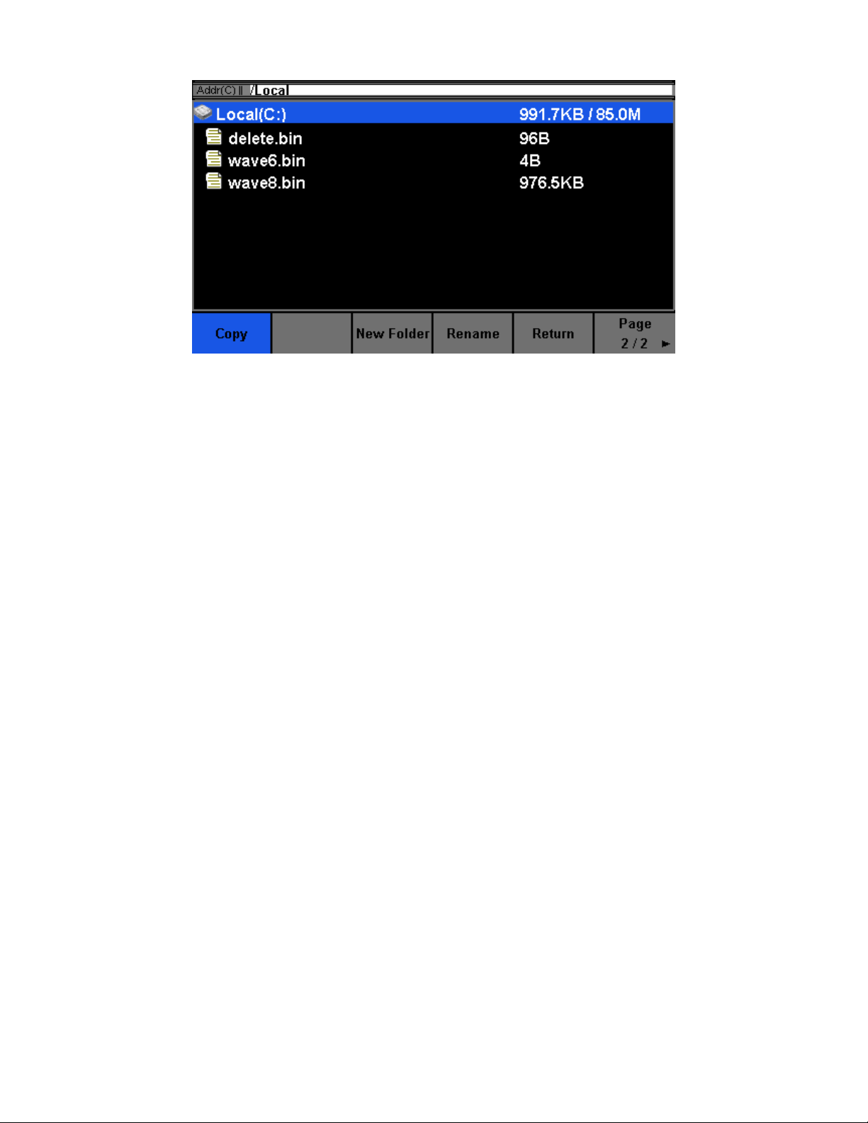
12.2.7 To Copy and Paste File
4060B Series supports the internal and external storage to copy les from each other. For example, copy an arbitrary
wave le in the U-disk to the instrument, the procedure is as follows:
1. Choose the le type.
Press Store/Recall → File Type, and choose “Data” as the storage type.
2. Choose the le to be copied.
Rotate the knob to select USB Device (0:) and press the knob to open its directory. Then rotate the knob to select the
le you want to copy and press Page 1/2 → Copy.
3. Paste the le.
Rotate the knob to select Local (C:) and press the knob to open its directory.
Then press Paste.
Page 60

Utility Function
With the Utility function, the user can set the parameters of the generator such as Sync, Interface, System Setting, Self
Test and Frequency Counter, etc. Press Utility to enter the utility menu, as shown in Figure 13.1.
Figure 13.1 Utility Menu
Page 61

Utility Function 61
System Set the system conguration.
Test/Cal Test and calibrate the instrument.
Counter Frequency counter setting.
Output Setup Set the output parameters of CH1 and CH2.
CH Copy Coupling Set the track, channel coupling or channel copy function.
Interface Set the parameters of remote interfaces.
Sync Set the sync output.
CLKSource Choose the system clock source, internal or external.
Help View the help information.
OverVoltage Protection Turn on/o the overvoltage protection function.
13.1 System Settings
Press Utility → System, to enter the following interface.
Figure 13.2 System Menu
Number format Set the number format.
Page 62
Utility Function 62
Language Set the language by pressing the button to toggle between English and Chinese.
PowerOn Set the power on behavior to load the defaults, or last used settings.
Set to Default Set all the settings to default values.
Beeper Enable or Disable the beep.
ScrnSvr Enable or disable the screen saver and set the time.
System Info View the system information
Firmware Update Update the rmware by the U-disk.
Bandwidth Update Update the bandwidth of the generator.
Done Save the current settings and return to the Utility menu.
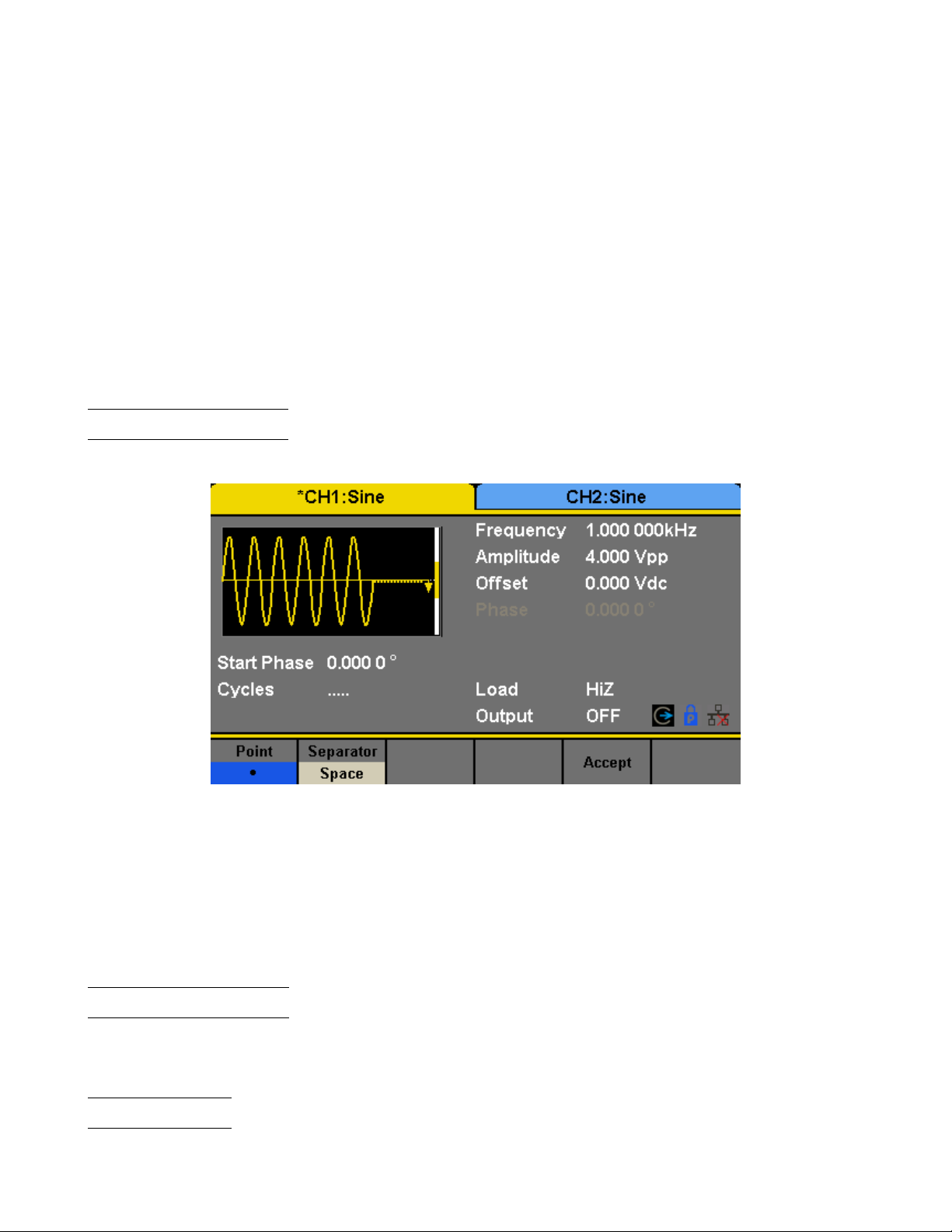
13.2 Number Format
Press Utility → System → Number Format, to enter the following interface.
Figure 13.3 Set the Number Format
Point Select either “.” or “,” to represent a decimal point.
Separator Select either a space, comma or no separator to show in large numbers.
Done Save the current settings and return to the System menu.
According to the dierent choices of the decimal point and the separator, the format can have various forms.
13.3 Language Setup
The generator oers two languages (English and Chinese). Press Utility → System → Language, to select the desired
language. This setting is stored in non-volatile memory and will not be inuenced by the Set To Default operation.
13.4 Power On
Choose the 4060B Series’s setting to load when the generator is powered on. Two choices are available: the default
setting and the last settings set when the unit was last powered down. Once selected, the setting will be applied when
Page 63

Utility Function 63
Figure 13.4 Chinese Interface
the instrument is powered on. This setting is stored in non-volatile memory and will not be inuenced by the Set To
Default operation.
Last includes all system parameters and states, except channel output state.
Default denotes the factory defaults except certain parameters (such as Language).
13.5 Set to Default
Press Utility → System → Set To Default, to set the system to the default setting. The default settings of the system
are as shown in Table 13.1.
13.6 Beep
Enable or disable the beeper. Press Utility →System → Beeper to select “On” or “O” and the default is “On”.
13.7 Screen Saver
Enable or disable screen saver. Press Utility → System → Page 1/2 → ScrnSvr to select “On” or “O” and the default
is “O”. Screen saver will be on if no action is taken within the time that you have selected. Click the touch screen or
Press any key to resume.
13.8 System Info
Select the System Info option of the utility menu to view the generator’s system information, including startup times,
software version, hardware version, model and serial number.
13.9 Software Update
The software version and conguration le of the generator can be updated directly via U-disk. Follow the steps below:
1. Insert U-disk with rmware update le (.ADS) and conguration le (.CFG) to USB host interface on the front panel
of the generator.
2. Press Utility → Page 1/2 → Firmware Update. Or press Store/Recall directly.
Page 64

Utility Function 64
Output Default
Function Sine Wave
Frequency 1kHz
Amplitude/Oset 4Vpp/0Vdc
Phase 0°
Load High Z
Modulation Default
Carrier 1kHz Sine Wave
Modulating 100Hz Sine Wave
AM Depth 100
FM Deviation 100Hz
ASK Key Frequency 100Hz
FSK Key Frequency 100Hz
FSK Hop Frequency 1MHz
PSK Key Frequency 100Hz
PM Phase Deviation 100°
PWM Width Dev 190s
Sweep Default
Start/Stop Frequency 500Hz/1.5kHz
Sweep Time 1s
Trig Out O
Mode Linear
Direction ↑
Burst Default
Burst Period 10ms
Start Phase 0°
Cycles 1Cycle
Trig Out O
Delay 521ns
Trigger Default
Source Internal
Table 13.1 Default Settings
3. Select the rmware le (.ADS) and choose Recall to update the system software.
4. After the updating is nished, the generator will restart automatically.
Note: Powering o the generator during a rmware update can corrupt the unit.
Note: A confmguration le (.CFG) may or may not be included with a given rmware update. If a CFG le is not
included with a rmware update then it will not be required for that update.
13.10 Built-in Help
The 4060B Series provides a built-in help system, by which users can view the help information at any time when operating
the instrument. Press Utility → System → Page 1/2 → Help to enter the following interface.
UP Cursor upward to select.
Page 65

Utility Function 65
Figure 13.5 System Information Interface
Figure 13.6 Help Menu
Down Cursor downward to select.
Select Read the currently selected help information.
Cancel Exit the built-in help system.
13.11 Test/Cal
Choose Utility → Test/Cal, to enter the following interface.
SelfTest Perform a system self-test.
TouchCal Do a touch screen calibration.
Return Return to the Utility menu.
13.11.1 Self Test
Press Utility → Test/Cal → SelfTest, to enter the following menu.
ScrTest Run screen test program.
Page 66

Utility Function 66
Figure 13.7 Test/Cal function Menu
Figure 13.8 Self Test Interface
KeyTest Run keyboard test program.
LEDTest Run key indicator lights test program.
BoardTest Run hardware circuit self-test program.
Cancel Return to the Test/Cal menu.
13.11.2 Screen Test
Select “ScrTest” to enter the screen test interface. The prompt message ‘Please press ‘7’ key to continue, press ‘8’ key
to exit.’ is displayed. Press the ‘7’ key for test and observe if there is any serious color deviation, bad pixel or display
error.
13.11.3 Key Test
Select KeyTest to enter the keyboard test interface, the on-screen white rectangle shapes represent the front panel keys.
The circle between two arrows represents the knob. Test all keys and knob and also verify that all the backlight keys
illuminate correctly.
The corresponding area of tested keys or knob would display in blue color.
The top of the screen displays ‘Please press ‘8’ key three times to exit.’
Page 67

Utility Function 67
13.11.4 LED Test
Select LEDTest to enter the LED test interface, the on-screen white rectangle shapes represent the front panel keys. The
prompt message ‘Please press ‘7’
Key to continue, press ‘8’ Key to exit.’ is displayed. Press the ‘7’ key continuously for testing and when a key is lighted,
the corresponding area on the screen will display in blue color.
Figure 13.9 LED Test Interface
13.11.5 Board Test
Select BoardTest to enter the following interface.
Figure 13.10 Board Test Interface
13.11.6 Touch Adjust
Use the function regularly to calibrate the touch screen, which makes it more accurate when the nger or touch pen
touches the screen and avoids any misoperation.
Press Utility → Test/Cal → TouchCal, to enter the following interface.
According to the messages on screen, click the red circle on screen in sequence. After touch calibration is done, the
system will display the following tip. Then press any key or touch the screen to exit the current interface.
Page 68

Utility Function 68
13.12 Frequency Counter
The 4060B Series provides a frequency counter which could measure frequencies between 100mHz to 200MHz. The dual
channels can still output normally when the counter is enabled. Press Utility → Counter, to enter the following interface.
Period Mode
Frequency Mode
Figure 13.11 Frequency Counter Interface
State Enable or Disable the counter.
Frequency Measured frequency.
Period Measured period.
PWidth Measured positive width.
NWidth Measured negative width.
RefFreq Set the reference frequency. System will calculate the deviation between the measured frequency
and the reference frequency automatically.
TrigLev Set the trigger level voltage.
Duty Measured duty cycle.
Setup Set the counter conguration.
Page 69
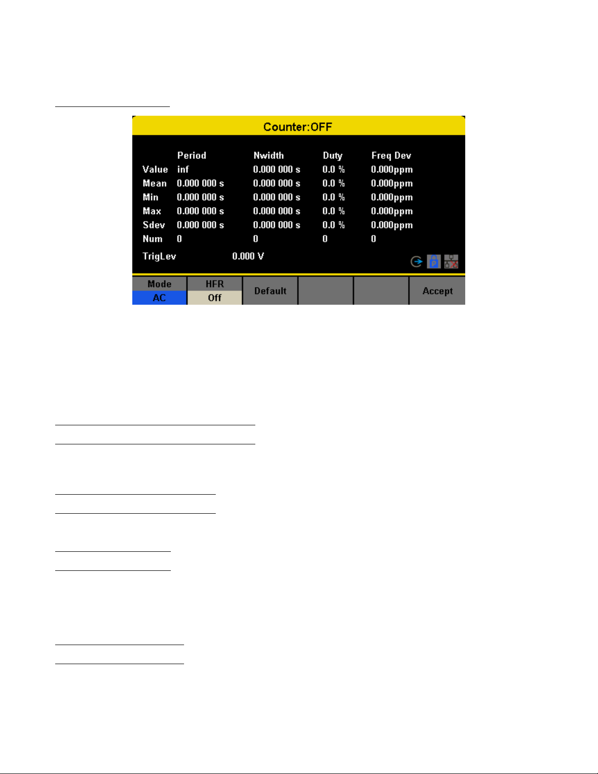
Utility Function 69
Cancel Exit the frequency counter.
13.12.1 Counter Setup
Figure 13.12 Counter Setup Interface
Mode Set the coupling mode to DC or AC
HFR High frequency rejection lter.
Default Set the frequency counter settings to default.
Done Save the current settings and return to the previous menu.
13.13 Parameters to be measured
The frequency counter on the 4060B Series can measure parameters including frequency, period, duty, positive pulse
width and negative pulse width.
13.14 Reference Frequency
System will calculate the deviation between the measured frequency and the reference frequency automatically.
13.15 Trigger Level
Sets the trigger level of the measurement system. The system triggers and obtains the measurement readings when the
input signal reaches the specied trigger level. The default is 0V and the available range is from -3V to 1.5V. Choose
TrigLev and use the numeric keyboard to input the desired value and select the unit (V or mV) from the pop-up menu.
Or use the knob and arrow keys to change the parameter value.
13.16 Coupling Mode
Sets the coupling model of the input signal to “AC” or “DC”. The default is “AC”.
Page 70

Utility Function 70
13.17 High Frequency Rejection
High Frequency Rejection can be used to lter out the high-frequency components of a measured signal and improve the
measurement accuracy in low-frequency signal measurement. Press HFR to enable or disable this function. The default
is “O”.
• Enable High Frequency Rejection when low-frequency signal with lower than a 250kHz frequency is measured to lter
out the high-frequency noise interference.
• Disable High Frequency Rejection when a signal with a frequency higher than 250 KHz is measured. The maximum
frequency that can be counted is 200 MHz.
13.18 Output
Press Utility → Output to enter the following interface.
Figure 13.13 Output Setup Interface
13.19 Load
For the [CH1] and [CH2] connectors on the front panel, the generator has an output impedance of 50Ω. If the actual
load does not match the set load, the displayed voltage will not be the same as the output voltage. This function is used
to match the displayed voltage with the expected one. This setting does not actually change the output impedance to
any other value.
13.19.1 Steps for setting the load:
Press Utility → Output Setup → Load, to set the output load. The load parameter shown on the down bottom is the
default setting when the power is on or the pre-set load value.
High Impedance: displayed as HiZ;
Load: the default is 50Ωand the range is 50Ωto 100kΩ.
Note: Continue pressing the corresponding output key for two seconds to switch between High Impedance and 50Ω.
13.20 Polarity
Press Utility → Output Setup → Polarity to set the output signal as normal or inverted. The waveform’s inversion is
relative to the oset voltage, as shown in the following gure.
Page 71

Utility Function 71
Note: The Sync signal related to the waveform is not inverted when the waveform is inverted.
13.21 EqPhase
Press Utility → Output Setup → EqPhase to align the phases of CH1 and CH2.
Choosing the menu will re-congure two channels and enable the generator to output with specied frequency and start
phase. For two signals whose frequencies are the same or a multiple thereof, this operation will align their phases.
13.22 Waveforms Combination Mode
The CH1 output port of the 4060B Series outputs the waveform of CH1 in the general mode, while the waveform of
CH1+CH2 can be output in the combined mode. Similarly, the CH2 output port of 4060B Series outputs the waveform
of CH2 in the general mode while the waveform of CH1+CH2 can be output in the combined mode.
Press Utility → Output Setup → Wave Combine to enter the waveforms combining interface, as shown in the following
gure.
CH1 Switch Output the waveform of CH1.
CH1+CH2 Output the waveform of CH1+CH2.
CH2 Switch Output the waveform of CH2.
CH1+CH2 Output the waveform of CH1+CH2.
Return Save the current operation and exit the current interface.
Note: When the waveforms combining function is enabled, the load of two channels will be set to the same automat-
ically, default using the load value of the currently operated channel.
13.23 CH Copy/Coupling
The 4060B Series supports state and waveform copy function between its two channels. That is to say, it copies all
parameters and states (including the channel output state) and arbitrary waveform data of one channel to the other one.
Press Utility → CH Copy Coupling → Channel Copy, to enter the following interface.
CH1=>CH2 Copy all parameters and states of CH1 to CH2.
CH2=>CH1 Copy all parameters and states of CH2 to CH1.
Accept Perform the current selection and return to the Utility menu.
Cancel Give up the current selection and return to the Utility menu.
Note: Channel coupling or track function and channel copy function are mutually exclusive. When channel coupling
or track function is enabled, the menu Channel Copy is hidden.
13.23.1 Channel Coupling
The 4060B Series supports frequency, amplitude and phase coupling. Users can set the frequency deviation/ratio,
amplitude deviation/ratio or phase deviation /ratio of the two channels. When coupling is enabled, CH1 and CH2 can
be modied simultaneously. When the frequency, amplitude or phase of one channel (as the reference) is changed, the
corresponding parameter of the other channel will be changed automatically and always keeps the specied frequency
deviation/ratio, amplitude deviation/ratio or phase deviation /ratio relative to the base channel.
Press Utility → CH Copy Coupling → Channel Coupling, to menu.
Page 72

Utility Function 72
Figure 13.14 Waveforms Combining Interface
13.23.2 Frequency Coupling
1. To Enable Frequency Coupling Function: Press FreqCoup to turn frequency coupling “On” or “O”. The default is
“O”.
2. To Select Frequency Coupling Mode: Press FreqMode to choose “Deviation” or “Ratio”, and then use the numeric
keyboard or knob and arrow keys to input the desired value.
Page 73

Utility Function 73
Figure 13.15 Channel Copy Interface
Deviation the frequency deviation between CH1 and CH2. 𝐹 𝑟𝑒𝑞
𝐹 𝑟𝑒𝑞
Ratio The frequency ratio of CH1 and CH2.
𝐹 𝑟𝑒𝑞
𝐶𝐻2
= 𝐹 𝑟𝑒𝑞𝑅𝑎𝑡𝑖𝑜.
𝐶𝐻1
𝐶𝐻2
− 𝐹 𝑟𝑒𝑞
= 𝐹 𝑟𝑒𝑞𝐷𝑒𝑣.
𝐶𝐻1
13.23.3 Amplitude Coupling
1. To Enable Amplitude Coupling Function: Press AmplCoup to turn amplitude coupling “On” or “O”. The default is
“O”.
2. To Select Amplitude Coupling Mode: Press AmplMode to choose “Deviation” or “Ratio”, and then use the numeric
keyboard or knob and arrow keys to input the desired value.
Deviation The amplitude deviation between CH1 and CH2. 𝐴𝑚𝑝𝑙
𝐴𝑚𝑝𝑙
Ratio the amplitude ratio of CH1 and CH2.
𝐴𝑚𝑝𝑙
𝐶𝐻2
= 𝐴𝑚𝑝𝑙𝑅𝑎𝑡𝑖𝑜.
𝐶𝐻1
𝐶𝐻2
− 𝐴𝑚𝑝𝑙
= 𝐴𝑚𝑝𝑙𝐷𝑒𝑣.
𝐶𝐻1
13.23.4 Phase Coupling
1. To Enable Phase Coupling Function: Press PhaseCoup to turn phase coupling “On” or “O”. The default is “O”.
2. To Select Phase Coupling Mode: Press PhaseMode to choose “Deviation” or “Ratio”, and then use the numeric
keyboard or knob and arrow keys to input the desired value.
𝑃 ℎ𝑎𝑠𝑒
Deviation the phase deviation between CH1 and CH2.
𝑃 ℎ𝑎𝑠𝑒
Ratio the phase ratio of CH1 and CH2.
𝑃 ℎ𝑎𝑠𝑒
𝐶𝐻2
𝐶𝐻1
𝐶𝐻2
𝑃 ℎ𝑎𝑠𝑒
= 𝑃 ℎ𝑎𝑠𝑒𝐷𝑒𝑣
𝐶𝐻1
= 𝑃 ℎ𝑎𝑠𝑒𝑅𝑎𝑡𝑖𝑜.
• Channel coupling is only available when both the waveforms of the two channels are basic waveforms including Sine,
Square, Ramp and Arbitrary.
• When the Phase Coupling function is enabled, if the phase of one channel is changed, the phase of the other channel
will be changed accordingly. At this point, aligning phase between the two channels can be achieved without executing
the Eqphase operation.
• Channel coupling and channel function are mutually exclusive. When channel coupling is enabled, the menu Channel
Copy is hidden.
Page 74
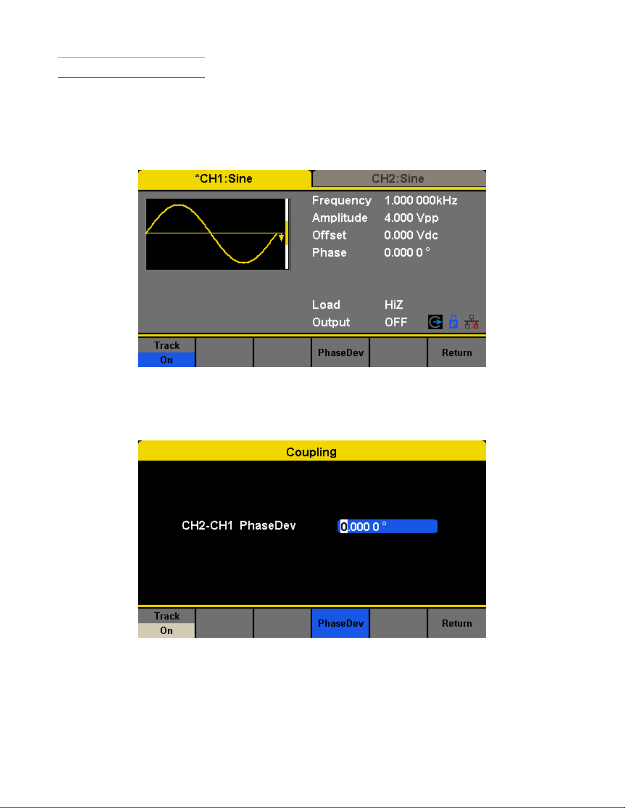
Utility Function 74
13.24 Channel Tracking
When the track function is enabled, by changing the parameters or states of CH1, the corresponding parameters or states
of CH2 will be adjusted to the same values or states automatically. At this point, the dual channels can output the same
signal.
Choose Utility → CH Copy Coupling → Track to enable or disable the track function. When the track function is enabled,
channel copy and coupling functions are disabled; the user interface is switched to CH1 and cannot be switched to CH2,
as shown in the following gure.
Figure 13.16 Track Interface
Press PhaseDev to enter the following interface. Then use the numeric keyboard or knob and arrow keys to input the
desired value for the phase deviation between CH1 and CH2. The resulting signal is represented by:
Phase
CH2
-Phase
=PhaseDev.
CH1
Figure 13.17 Phase Deviation Interface
Page 75

Output Synchronization
The generator provides Sync output through the [Aux In/Out] connector on the rear panel. When the synchronization is
on, the port can output a CMOS signal with the same frequency as basic waveforms (except Noise and DC), arbitrary
waveforms, and modulated waveforms (except external modulation).
Function Description
State O Close the sync output
On Open the sync output
Channel CH1 Set the sync signal of CH1.
CH2 Set the sync signal of CH2.
Accept Save the current settings and return to the Utility menu.
Cancel Give up the current settings and return to the Utility menu.
Figure 14.1 Sync Output Interface
14.1 Sync Signals of Dierent Waveforms
1. When the frequency of the waveform is less than or equal to 10MHz, the sync signal is a Pulse with 50ns pulse width
and the same frequency as the waveform.
2. When the frequency of the waveform is greater than 10MHz, there is no sync signal output.
3. Noise and DC: there is no sync signal output.
14.1.1 Modulated Waveform
• When internal modulation is selected, the sync signal is a Pulse with 50ns pulse width.
For AM, FM, PM and PWM, the frequency of the sync signal is the modulating frequency.
For ASK, FSK and PSK, the frequency of the sync signal is the key frequency.
• When external modulation is selected, there is no sync signal output, for the [Aux In/Out] connector on the rear panel
is used to input external modulating signal.
14.1.2 Sweep and Burst Waveform
When Sweep or Burst function is turned on, there is no sync signal output and the Sync menu is hidden.
Page 76

Clock Source
The 4060B Series provides an internal 10MHz clock source. It also can accept external clock source form the [10 MHz
In/Out] connector at the rear panel. It can also output the clock source from the [10 MHz In/Out] connector for other
devices.
Press Utility → Page 1/2 → Clock → Source to select “Internal” or “External”.
If “External” is selected, the instrument will detect whether a valid external clock signal is input from the [10MHz In/Out]
connector at the rear panel. If not, the prompt message “No external clock source!” would be displayed and the clock
source would be switched to “Internal”.
15.1 Sync methods for two or more instruments:
Connect the [10MHz In/Out] connector of generator A (using internal clock) to the [10MHz In/Out] connector of
generator B (using external clock) and set the output frequencies of A and B as a same value to realize synchronization.
15.2 Synchronization among multiple instruments
Divide the 10MHz clock source of a generator (using internal clock) into multiple channels, and then connect them to
the [10MHz In/Out] connectors of other generators (using External clock), and nally set the output frequencies of all
the generators as a same value to realize synchronization.
Page 77

Channel Phase Mode
Press Utility → Page 1/2 → Mode to enter the mode setup Interface, as shown in Figure 16.1.
Figure 16.1 Mode Setup Interface
Phase-locked Mode When changing the frequency, the DDSs of both channels reset, and the phase deviation between
CH1 and CH2 is maintained.
Independent Mode When changing the frequency, neither channels’ DDS resets and the phase deviation between CH1
and CH2 changes at random. When the independent mode is enabled, the phase parameter cannot be modied and the menu Phase is hidden.
Page 78

Overvoltage Protection
Choose Utility → Page 1/2 → OverVoltage Protection to turn on or o the function.
If the state is set to ON, overvoltage protection of CH1 and CH2 will take eect once any of the following conditions is
met. When overvoltage protection occurs, a message will be displayed and the output is disabled.
• The absolute value of input voltage is higher than 11V±0.5V when the amplitude of the generator is higher than or
equal to 3.2Vpp or the DC oset is higher than or equal to |2VDC|.
• The absolute value of input voltage is higher than 4V±0.5V when the amplitude of the generator is lower than 3.2Vpp
or the DC oset is lower than |2VDC|.
Page 79

Remote Interface
The 4060B Series can be controlled remotely via USB, LAN and GPIB (option) interfaces. Users can set the corresponding
interface according to their needs.
Press Utility → Page 1/2 → Interface to open the following menu. The user can set LAN parameters or GPIB address.
Figure 18.1 Interface Settings
GPIB Set the GPIB address.
LAN State Turn on LAN.
LAN Setup Set the IP address, subnet mask, gateway and DHCP.
Accept Save the current settings and return to the Utility menu.
The 4060B Series can be controlled remotely via the following two methods:
18.1 User-dened programming
Users can program and control the instrument by using the SCPI commands (Standard Commands for Programmable
Instruments). For more information about the commands and programming, please refer to “Remote Control Manual”.
18.2 Remote Control via USB
The 4060B Series can communicate with a PC through the USBTMC protocol.
You are suggested to do as the following steps.
1. Connect the device: Connect the USB Device interface at the rear panel of 4060B Series with the PC via a USB
cable.
2. Install the USB driver: NI Visa is recommended.
3. Communicate with a remote PC: Open Measurement & Automation Explorer of NI and choose the corresponding
resource name. Then click “Open VISA Test Panel” to turn on the remote command control panel through which
you can send commands and read data.
Page 80

Remote Interface 80
18.3 Remote Control via GPIB
Each device connected to GPIB interface must have a unique address. The default value is 18 and values range from 1
to 30. The selected address is stored in non-volatile memory.
Choose Utility → Page 1/2 → Interface → GPIB to enter the following interface.
18.4 Remote Control via LAN
The 4060B Series can communicate with a PC through the LAN interface. Users can view and modify the LAN parameters.
Choose Utility → Page 1/2 → Interface → LAN State to turn on LAN. Then choose LAN Setup to enter the interface
conguration values. If available, DHCP (Dynamic Host Conguration Protocol), can set the appropriate values for
networks that provide a DHCP server.
Page 81

Specications
Note: All specications apply to the unit after:
1. A temperature stabilization time of 15 minutes over an ambient temperature range of 23∘C±5∘C.
2. Short correction operation performed before making measurement.
Specications are subject to change without notice.
Page 82

Dual Channel Function/Arbitrary Waveform Generators
4060B Series
5
www.bkprecision.com
Specifications
Model 4062B 4063B 4064B
Channels 2
Frequency Characteristics
Sine 1 µHz to 40 MHz 1 µHz to 80 MHz 1 µHz to 120 MHz
Square 1 µHz to 25 MHz
Triangle, Ramp 1 µHz to 1 MHz
Pulse 1 µHz to 25 MHz
Gaussian Noise (-3 dB) > 120 MHz
Arbitrary 1 µHz to 20 MHz
Accuracy ± 1 ppm (1 year)
Resolution 1 µHz
Note: All specifications apply to the unit after a temperature stabilization time of 30 minutes over an ambient temperature range of 23 °C ± 5 °C.
Arbitrary Characteristics
Built-in Waveforms 196
Waveform Length 8 points to 8 M points
Vertical Resolution 16 bits
Sampling Rate
300 MSa/s (DDS mode)
75 MSa/s (true arbitrary mode)
Minimum Rise/Fall
Time (typical)
4.5 ns (DDS mode)
8.5 ns (true arbitrary mode)
Jitter (rms) < 150 ps (1 Vpp, into 50 Ω load, true arbitrary mode)
Non-volatile Memory
Storage
80 MB file system
Output Characteristics
Amplitude Range
(1)
(into open circuit)
2 mVpp to 20 Vpp ( ≤ 20 MHz)
2 mVpp to 10 Vpp ( > 20 MHz)
Amplitude Resolution Up to 4 digits
Amplitude Accuracy
(10 kHz, 0 V offset)
± (1% + 1 mVpp)
Amplitude Flatness
(reference to 10 kHz
Sine, 2.5 Vpp)
± 0.3 dB (50 Ω load, DC to 100 MHz)
± 0.4 dB (50 Ω load, 100 MHz to 120 MHz)
Cross Talk < -60 dBc (between channels)
Offset Range (DC)
± 5 V (into 50 Ω load)
± 10 V (into open circuit)
Offset Resolution (DC) Up to 4 digits
Offset Accuracy (DC) ± (1% + 2 mV), into open circuit
Output Impedance
(typical)
50 Ω
Output Protection Overvoltage (see user manual for details)
Waveform Characteristics
Harmonic Distortion
(sine, 0 dBm input,
typical)
DC to 10 MHz, < -65 dBc
10 MHz to 20 MHz, < -60 dBc
20 MHz to 40 MHz, < -55 dBc
40 MHz to 60 MHz, < -50 dBc
60 MHz to 80 MHz, < -45 dBc
80 MHz to 100 MHz, < -40 dBc
100 MHz to 120 MHz, < -38 dBc
(1) This specification will be divided by 2 while applied to a 50 Ω load.
(2) Modulation schemes not available in DC mode.
Waveform Characteristics (continued)
Total Harmonic
Distortion (sine)
< 0.075% (10 Hz to 20 kHz at 0 dBm)
Spurious
(non-harmonic)
≤ 50 MHz, -70 dBc max.
> 50 MHz, -65 dBc max.
Rise/Fall Time (square) < 9 ns (10% to 90% at 1 Vpp, into 50 Ω load)
Variable Duty Cycle
(square)
0.001% to 99.999%
(depending on frequency setting)
Jitter (rms) Cycle to
Cycle (square)
150 ps (1 Vpp, into 50 Ω load, typical)
Ramp Symmetry 0% to 100%
Ramp Linearity
< 1% of peak output (triangle, ramp at 1 kHz, 1 Vpp, 100%
symmetry)
Pulse
Pulse Width 16.3 ns minimum
Rise/Fall Time 8.4 ns to 22.4 s (1 Vpp, 10% to 90%, into 50 Ω load)
Duty Cycle Range 0.001% to 99.999% (depending on frequency setting)
Overshoot < 3% (100 kHz, 1 Vpp)
Jitter (rms)
Cycle to Cycle
150 ps (1 Vpp, into 50 Ω load)
Burst
Waveform Sine, square, ramp, pulse, arbitrary, noise
Type Cycle (1 to 1,000,000 cycles), infinite, gated
Start/Stop Phase 0º to 360º
Internal Period 1 µs to 1000 s
Gated Source Internal, external trigger
Trigger Source Internal, external, manual
Phase Offset
Range -360º to 360º
Resolution 0.1º
AM, FM & PM Modulation Characteristics
Carrier
(2)
Sine, square, ramp, arbitrary
Source Internal, external
Modulation Waveform Sine, square, ramp, noise, arbitrary
AM Modulation Depth 0% to 120%
FM Frequency Deviation
0 to 0.5 x (maximum output frequency)
PM Phase Deviation 0º to 360º
ASK & FSK Modulation Characteristics
Carrier
(2)
Sine, square, ramp, arbitrary
Source Internal, external
Modulation Waveform 50% duty cycle square waveform
Page 83

Dual Channel Function/Arbitrary Waveform Generators
4060B Series
6
www.bkprecision.com
v120919
Specifications (continued)
Model 4062B, 4063B, 4064B
DSB-AM Modulation Characteristics
Carrier
(2)
Sine, square, ramp, arbitrary
Source Internal, external
Modulation Waveform Sine, square, ramp, noise, arbitrary
PWM Modulation Characteristics
Source Internal, external
Modulation Waveform
(2)
Sine, square, ramp, noise, arbitrary
Internal Modulation
Frequency
1 mHz to 1 MHz
Sweep Characteristics
Waveforms
(2)
Sine, square, ramp, arbitrary
Sweep Shape Linear or logarithmic, up or down
Sweep Time 1 ms to 500 s
Sweep Trigger Internal, external, manual
Harmonic Output Characteristics
Maximum Order 16
Type Even, odd, all
Auxiliary Input / Output
Sync Out
TTL compatible
(4)
Output impedance: 100 Ω (typical)
Maximum frequency: 10 MHz
Minimum pulse width: 50 ns (typical)
Modulation Input
± 12 Vpp (typical) for 100% modulation
Input impedance: 10 kΩ
Frequency range: 0 kHz to 50 kHz
Trigger
Input
Level TTL compatible
(3)
Slope Rising or falling, selectable
Pulse Width > 100 ns
Impedance > 100 kΩ
Latency
100 ns maximum (sweep mode)
600 ns maximum (burst mode)
Output
Voltage
Level
TTL compatible
(4)
Pulse Width > 500 ns
Impedance 100 Ω (typical)
Maximum
Frequency
1 MHz
Reference Clock
Input
Frequency range: 10 MHz (typical)
Minimum voltage input: 1.4 Vpp
Input impedance: 5 kΩ
Output
Frequency range: 10 MHz (typical)
Voltage level: 3.3 V (typical), 2 V (minimum)
Output impedance: 50 Ω
Frequency Counter
Measurement Frequency, period, positive/negative pulse width, duty cycle
Measurement Range
100 mHz to 200 MHz (DC coupling)
10 Hz to 200 MHz (AC coupling)
Input Range
100 mVrms to ± 2.5 V (< 100 MHz, DC coupling)
200 mVrms to ± 2.5 V (100 MHz to 200 MHz,
DC coupling)
100 mVrms to 5 Vpp (< 100 MHz, AC coupling)
200 mVrms to 5 Vpp (100 MHz to 200 MHz, AC coupling)
Input Impedance 1 MΩ (typical)
Coupling AC, DC, HF REJ (≥ 250 kHz filter)
Environmental and Safety
Temperature
Operating: 32 °F to 104 °F (0 °C to 40 °C)
Storage: -4 °F to 140 °F (-20 °C to 60 °C)
Humidity
< 86 °F (30 °C), ≤ 90 % RH
104 °F (40 °C), ≤ 50 % RH
Altitude
Operating: below 10,000 ft (3,048 m)
Storage: below 49, 212 ft (15,000 m)
Electromagnetic
Compatibility
EMC Directive 2014/30/EU, EN61326-1:2013
Safety Low voltage directive (LVD) 2014/35/EU, EN61010-1:2010
General
Display 4.3” TFT color (24-bit) LCD touch screen
I/O Interfaces USBTMC device, LAN, USB host port
Storage Memory 10 instrument settings
AC Input
100 to 240 VAC ± 10 %, 50/60 Hz
100 to 120 VAC ± 10 %, 400 Hz
Power Consumption 50 W maximum
Dimensions
(W x H x D)
10.25” x 4.22” x 11.61” (260.3 x 107.2 x 295 mm)
Weight 7.6 lbs (3.43 kg)
Warranty 3 years
Standard Accessories
AC power cord, user manual (downloadable),
USB type A-to-B cable, BNC coaxial cable,
certificate of calibration
Optional Accessories USB-to-GPIB adapter (model AK40G)
(2) Modulation schemes not available in DC mode.
(3) VIH = 2 V to 5.5 V, VIL = 0.5 V to 0.8 V
(4) VOH = 3.8 V (IOH = -8 mA), VOL = 0.44 V (IOL = 8 mA)
Page 84

1 Common Waveforms
StairUp Stair waveform, rising
StairDn Stair waveform, falling
StairUD Stair waveform, rising and falling
Trapezia Trapezoidal waveform
Ppulse Positive pulse
Npulse Negative pulse
UpRamp UpRamp waveform
DnRamp DnRamp waveform
SineTra Sine-Tra waveform
SineVer Sine-Ver waveform
Appendix: Waveforms
20.1 Math Waveforms
ExpFall Exponential Decay function
ExpRise Exponential Rise function
LogFall Logarhythmic Fall function
LogRise Logarhythmic Rise function
Sqrt Square Root function
Root3 Root3 function
X^2 X2function
X^3 X3function
Airy Airy function
Besselj Bessel I function
Bessely Bessel II function
Dirichlet Dirichlet function
Erf Error function
Erfc Complementary error function
ErfcInv Inverted complementary error function
ErfInv Inverted error function
Laguerre 4-times Laguerre polynomial
Page 85

Appendix: Waveforms 83
Legend 5-times Legend polynomial
Versiera Versiera
Sinc Sinc function
Gaussian Gaussian function
Dlorentz Dlorentz function
Haversine Haversine function
Lorentz Lorentz function
Gauspuls Gauspuls signal
Gmonopuls Gmonopuls signal
Tripuls Tripuls signal
Weibull Weibull distribution
LogNormal LogNormal Gaussian distribution
Laplace Laplace distribution
Maxwell Maxwell distribution
Rayleigh Rayleigh distribution
Cauchy Cauchy distribution
20.2 Engine Waveforms
Cardiac Cardiac signal
Quake Analog quake waveform
Chirp Chirp signal
TwoTone TwoTone signal
SNR SNR signal
AmpALT Gain oscillation curve
AttALT Attenuation oscillation curve
RoundHalf RoundHalf Waveform
RoundsPM RoundsPM Waveform
BlaseiWave Time-velocity curve of explosive oscillation
DampedOsc Time-displacement curve of damped oscillation
SwingOsc Kinetic energy – time curve of swing oscillation
Discharge Discharge curve of NI-MH battery
Pahcur Current waveform of DC brushless motor
Combin Combination function
Page 86

Appendix: Waveforms 84
SCR SCR ring prole
TV TV signal
Voice Voice signal
Surge Surge signal
Radar Analog radar signal
Ripple Ripple wave of battery
Gamma Gamma signal
StepResp Step-response signal
BandLimited Bandwidth-limited signal
CPulse C-Pulse
CWPulse CW pulse
GateVibr Gate self-oscillation signal
LFMPulse Linear FM pulse
MCNoise Mechanical construction noise
20.3 Window Waveforms
Hamming Hamming window
Hanning Hanning window
Kaiser Kaiser window
Blackman Blackman window
GaussiWin GaussiWin window
Triangle Triangle window (Fejer window)
BlackmanH BlackmanH window
Bartlett-Hann Bartlett-Hann window
Bartlett Bartlett window
BarthannWin Modied Bartlett-Hann window
BohmanWin BohmanWin window
ChebWin ChebWin window
FlattopWin Flat top weighted window
ParzenWin ParzenWin window
TaylorWin TaylorWin window
TukeyWin TukeyWin (tapered cosine) window
Page 87

Appendix: Waveforms 85
20.4 Trigonometric Waveforms
Tan Tangent
Cot Cotangent
Sec Secant
Csc Cosecant
Asin Arc sine
Acos Arc cosine
Atan Arc tangent
ACot Arc cotangent
CosH Hyperbolic cosine
CosInt Integral cosine
Coth Hyperbolic cotangent
Csch Hyperbolic cosecant
SecH Hyperbolic secant
SinH Hyperbolic sine
SinInt Integral sine
TanH Hyperbolic tangent
ACosH Arc hyperbolic cosine
ASecH Arc hyperbolic secant
ASinH Arc hyperbolic sine
ATanH Arc hyperbolic tangent
ACsch Arc hyperbolic cosecant
ACoth Arc hyperbolic cotangent
20.5 Square Waveforms
Square waveforms with duty cycle percentages from 1 to 99% are shown in a table after pressing the “Square” button.
They are organized in 3 pages. If the desired percentage is higher than shown on screen, select the last eld in the table
“pageX” and press the knob to navigate to the next page. To return to a lower percentage than shown, do the same by
selecting the rst cell in the table showing “pageX” in the upper left corner of the table.
SquareDutyXX Is the name of the waveform with XX dening the percentage duty cycle. “XX” is replaced by
the desired percentage. For example, 10% is “SquareWave10”.
20.6 Medical Waveforms
Waveform Description
EOG Electro-Oculogram
Page 88

Appendix: Waveforms 86
EEG Electroencephalogram
EMG Electromyogram
Pulseilogram Pulseilogram
ResSpeed Speed curve of the respiration
ECG1 Electrocardiogram 1
ECG2 Electrocardiogram 2
ECG3 Electrocardiogram 3
ECG4 Electrocardiogram 4
ECG5 Electrocardiogram 5
ECG6 Electrocardiogram 6
ECG7 Electrocardiogram 7
ECG8 Electrocardiogram 8
ECG9 Electrocardiogram 9
ECG10 Electrocardiogram 10
ECG11 Electrocardiogram 11
ECG12 Electrocardiogram 12
ECG13 Electrocardiogram 13
ECG14 Electrocardiogram 14
ECG15 Electrocardiogram 15
LFPulse Waveform of the low frequency pulse electrotherapy
Tens1 Waveform 1 of the nerve stimulation electrotherapy
Tens2 Waveform 2 of the nerve stimulation electrotherapy
Tens3 Waveform 3 of the nerve stimulation electrotherapy
20.7 Modulated Waveforms
AM Sectional sine AM signal
FM Sectional sine FM signal
PFM Sectional pulse FM signal
PM Sectional sine PM signal l
PWM Sectional PWM signal
20.8 Filter Waveforms
Butterworth Butterworth lter
Chebyshev1 Chebyshev1 lter
Page 89

Appendix: Waveforms 87
Chebyshev2 Chebyshev2 lter
20.9 Demo Waveforms
demo1_375pts TureArb waveform 1 375 pts
demo1_16kpts TureArb waveform 1 16384 pts
demo2_3kpts TureArb waveform 2 3000 pts
demo2_16kpts TureArb waveform 2 16384 pts
Page 90

Daily Maintenance
Do not store or leave the instrument in where the display screen will be exposed to direct sunlight for a long period of
time.
CAUTION: To avoid damage to the instrument, do not expose it to spray, liquid, or solvent.
21.1 Cleaning
If the instrument requires cleaning, disconnect it from all power sources and clean it with a mild detergent and water.
Make sure the instrument is completely dry before reconnecting it to a power source.
To clean the exterior surface, perform the following steps:
1. Remove loose dust on the outside of the instrument with a lint-free cloth. When cleaning the touch screen, be careful
to avoid scratching the transparent plastic protective screen.
2. Use a soft cloth dampened with water to clean the instrument.
WARNING: To avoid any damage to the surface of the instrument, do not use any abrasive or chemical cleaning agents.
Page 91

LIMITED THREE-YEAR WARRANTY
B&K Precision Corp. warrants to the original purchaser that its products and the component parts thereof, will be free
from defects in workmanship and materials for a period of three years from date of purchase.
B&K Precision Corp. will, without charge, repair or replace, at its option, defective product or component parts. Returned
product must be accompanied by proof of the purchase date in the form of a sales receipt.
To help us better serve you, please complete the warranty registration for your new instrument via our website www.bkprecision.com
Exclusions: This warranty does not apply in the event of misuse or abuse of the product or as a result of
unauthorized alterations or repairs. The warranty is void if the serial number is altered, defaced or removed.
B&K Precision Corp. shall not be liable for any consequential damages, including without limitation damages resulting
from loss of use. Some states do not allow limitations of incidental or consequential damages. So the above limitation
or exclusion may not apply to you.
This warranty gives you specic rights and you may have other rights, which vary from state-to-state.
B&K Precision Corp.
22820 Savi Ranch Parkway
Yorba Linda, CA 92887
www.bkprecision.com
714-921-9095
Page 92

Service Information
Warranty Service
Please go to the support and service section on our website at bkprecision.com to obtain an RMA #. Return the product
in the original packaging with proof of purchase to the address below. Clearly state on the RMA the performance problem
and return any leads, probes, connectors and accessories that you are using with the device.
Non-Warranty Service
Please go to the support and service section on our website at bkprecision.com to obtain an RMA #. Return the product
in the original packaging to the address below. Clearly state on the RMA the performance problem and return any leads,
probes, connectors and accessories that you are using with the device. Customers not on an open account must include
payment in the form of a money order or credit card. For the most current repair charges please refer to the service and
support section on our website.
Return all merchandise to B&K Precision Corp. with prepaid shipping. The at-rate repair charge for Non-Warranty
Service does not include return shipping. Return shipping to locations in North America is included for Warranty Service.
For overnight shipments and non-North American shipping fees please contact B&K Precision Corp.
B&K Precision Corp.
22820 Savi Ranch Parkway
Yorba Linda, CA 92887
http://bkprecision.com
714-921-9095
Include with the returned instrument your complete return shipping address, contact name, phone number and description
of problem.
Version: December 19, 2019
 Loading...