

Page 1
i
4050B Series
Function/Arbitrary Waveform
Generator
USER MANUAL
www. .com
information@itm.com1.800.561.8187
Page 2

Safety Summary
The following safety precautions apply to both operating and maintenance personnel and must
be followed during all phases of operation, service, and repair of this instrument.
Before applying power to this instrument:
Read and understand the safety and operational information in this manual.
Apply all the listed safety precautions.
Verify that the voltage selector at the line power cord input is set to the correct line
voltage. Operating the instrument at an incorrect line voltage will void the warranty.
Make all connections to the instrument before applying power.
Do not operate the instrument in ways not specified by this manual or by B&K Precision.
Failure to comply with these precautions or with warnings elsewhere in this manual violates the
safety standards of design, manufacture, and intended use of the instrument. B&K Precision
assumes no liability for a customer’s failure to comply with these requirements.
Category rating
The IEC 61010 standard defines safety category ratings that specify the amount of electrical
energy available and the voltage impulses that may occur on electrical conductors associated
with these category ratings. The category rating is a Roman numeral of I, II, III, or IV. This rating
is also accompanied by a maximum voltage of the circuit to be tested, which defines the voltage
impulses expected and required insulation clearances. These categories are:
Category I (CAT I): Measurement instruments whose measurement inputs are not intended to
be connected to the mains supply. The voltages in the environment are typically derived from a
limited-energy transformer or a battery.
Category II (CAT II): Measurement instruments whose measurement inputs are meant to be
connected to the mains supply at a standard wall outlet or similar sources. Example
measurement environments are portable tools and household appliances.
Category III (CAT III): Measurement instruments whose measurement inputs are meant to be
connected to the mains installation of a building. Examples are measurements inside a
building's circuit breaker panel or the wiring of permanently-installed motors.
i
www. .com
information@itm.com1.800.561.8187
Page 3

Category IV (CAT IV): Measurement instruments whose measurement inputs are meant to be
connected to the primary power entering a building or other outdoor wiring.
Do not use this instrument in an electrical environment with a higher category rating than what
is specified in this manual for this instrument.
You must ensure that each accessory you use with this instrument has a category rating equal
to or higher than the instrument's category rating to maintain the instrument's category rating.
Failure to do so will lower the category rating of the measuring system.
Electrical Power
This instrument is intended to be powered from a CATEGORY II mains power environment. The
mains power should be 120 V RMS or 240 V RMS. Use only the power cord supplied with the
instrument and ensure it is appropriate for your country of use.
Ground the Instrument
To minimize shock hazard, the instrument chassis and cabinet must be connected to an
electrical safety ground. This instrument is grounded through the ground conductor of the
supplied, three-conductor AC line power cable. The power cable must be plugged into an
approved three-conductor electrical outlet. The power jack and mating plug of the power cable
meet IEC safety standards.
Do not alter or defeat the ground connection. Without the safety ground connection, all
accessible conductive parts (including control knobs) may provide an electric shock. Failure to
use a properly-grounded approved outlet and the recommended three-conductor AC line
power cable may result in injury or death.
ii
www. .com
information@itm.com1.800.561.8187
Page 4

Unless otherwise stated, a ground connection on the instrument's front or rear panel is for a
reference of potential only and is not to be used as a safety ground.
Do not operate in an explosive or flammable atmosphere
Do not operate the instrument in the presence of flammable gases or vapors, fumes, or finelydivided particulates.
The instrument is designed to be used in office-type indoor environments. Do not operate the
instrument
In the presence of noxious, corrosive, or flammable fumes, gases, vapors, chemicals, or
finely-divided particulates.
In relative humidity conditions outside the instrument's specifications.
In environments where there is a danger of any liquid being spilled on the instrument or
where any liquid can condense on the instrument.
In air temperatures exceeding the specified operating temperatures.
In atmospheric pressures outside the specified altitude limits or where the surrounding
gas is not air.
In environments with restricted cooling air flow, even if the air temperatures are within
specifications.
In direct sunlight.
This instrument is intended to be used in an indoor pollution degree 2 environment. The
operating temperature range is 0 °C to 40 °C and the operating humidity is ≤ 90 % relative
humidity at < 35 °C and ≤ 60 % relative humidity at 35 °C – 40 °C, with no condensation allowed.
iii
www. .com
information@itm.com1.800.561.8187
Page 5

Measurements made by this instrument may be outside specifications if the instrument is used
in non-office-type environments. Such environments may include rapid temperature or
humidity changes, sunlight, vibration and/or mechanical shocks, acoustic noise, electrical noise,
strong electric fields, or strong magnetic fields.
Do not operate instrument if damaged
If the instrument is damaged, appears to be damaged, or if any liquid, chemical, or other
material gets on or inside the instrument, remove the instrument's power cord, remove the
instrument from service, label it as not to be operated, and return the instrument to B&K
Precision for repair. Notify B&K Precision of the nature of any contamination of the instrument.
Clean the instrument only as instructed
Do not clean the instrument, its switches, or its terminals with contact cleaners, abrasives,
lubricants, solvents, acids/bases, or other such chemicals. Clean the instrument only with a
clean dry lint-free cloth or as instructed in this manual.
Not for critical applications
This instrument is not authorized for use in contact with the human body or for use as a
component in a life-support device or system.
iv
www. .com
information@itm.com1.800.561.8187
Page 6

Do not touch live circuits
Instrument covers must not be removed by operating personnel. Component replacement and
internal adjustments must be made by qualified service-trained maintenance personnel who
are aware of the hazards involved when the instrument's covers and shields are removed.
Under certain conditions, even with the power cord removed, dangerous voltages may exist
when the covers are removed. To avoid injuries, always disconnect the power cord from the
instrument, disconnect all other connections (for example, test leads, computer interface
cables, etc.), discharge all circuits, and verify there are no hazardous voltages present on any
conductors by measurements with a properly-operating voltage-sensing device before touching
any internal parts. Verify the voltage-sensing device is working properly before and after
making the measurements by testing with known-operating voltage sources and test for both
DC and AC voltages. Do not attempt any service or adjustment unless another person capable of
rendering first aid and resuscitation is present.
Do not insert any object into an instrument's ventilation openings or other openings.
Hazardous voltages may be present in unexpected locations in circuitry being tested when a
fault condition in the circuit exists.
Servicing
Do not substitute parts that are not approved by B&K Precision or modify this instrument.
Return the instrument to B&K Precision for service and repair to ensure that safety and
performance features are maintained.
v
www. .com
information@itm.com1.800.561.8187
Page 7

Cooling fans
This instrument contains one or more cooling fans. For continued safe operation of the
instrument, the air inlet and exhaust openings for these fans must not be blocked nor must
accumulated dust or other debris be allowed to reduce air flow. Maintain at least 25 mm
clearance around the sides of the instrument that contain air inlet and exhaust ports. If
mounted in a rack, position power devices in the rack above the instrument to minimize
instrument heating while rack mounted. Do not continue to operate the instrument if you
cannot verify the fan is operating (note some fans may have intermittent duty cycles). Do not
insert any object into the fan's inlet or outlet.
For continued safe use of the instrument
Do not place heavy objects on the instrument.
Do not obstruct cooling air flow to the instrument.
Do not place a hot soldering iron on the instrument.
Do not pull the instrument with the power cord, connected probe, or connected test
lead.
Do not move the instrument when a probe is connected to a circuit being tested.
vi
www. .com
information@itm.com1.800.561.8187
Page 8

Compliance Statements
This product is subject to Directive 2002/96/EC of the European
Parliament and the Council of the European Union on waste
electrical and electronic equipment (WEEE), and in jurisdictions
adopting that Directive, is marked as being put on the market after
August 13, 2005, and should not be disposed of as unsorted
municipal waste. Please utilize your local WEEE collection facilities
in the disposition of this product and otherwise observe all
applicable requirements.
Disposal of Old Electrical & Electronic Equipment (Applicable in the European
Union and other European countries with separate collection systems)
www. .com
vii
information@itm.com1.800.561.8187
Page 9

CE Declaration of Conformity
This instrument meets the requirements of 2006/95/EC Low Voltage Directive and 2004/108/EC
Electromagnetic Compatibility Directive with the following standards.
Low Voltage Directive
o EN61010-1: 2001
EMC Directive
o EN 61000-3-2: 2006
o EN 61000-3-3: 1995+A1: 2001+A2: 2005
o EN 61000-4-2 / -3 / -4 / -5 / -6 / -11
o EN 61326-1: 2006
viii
www. .com
information@itm.com1.800.561.8187
Page 10
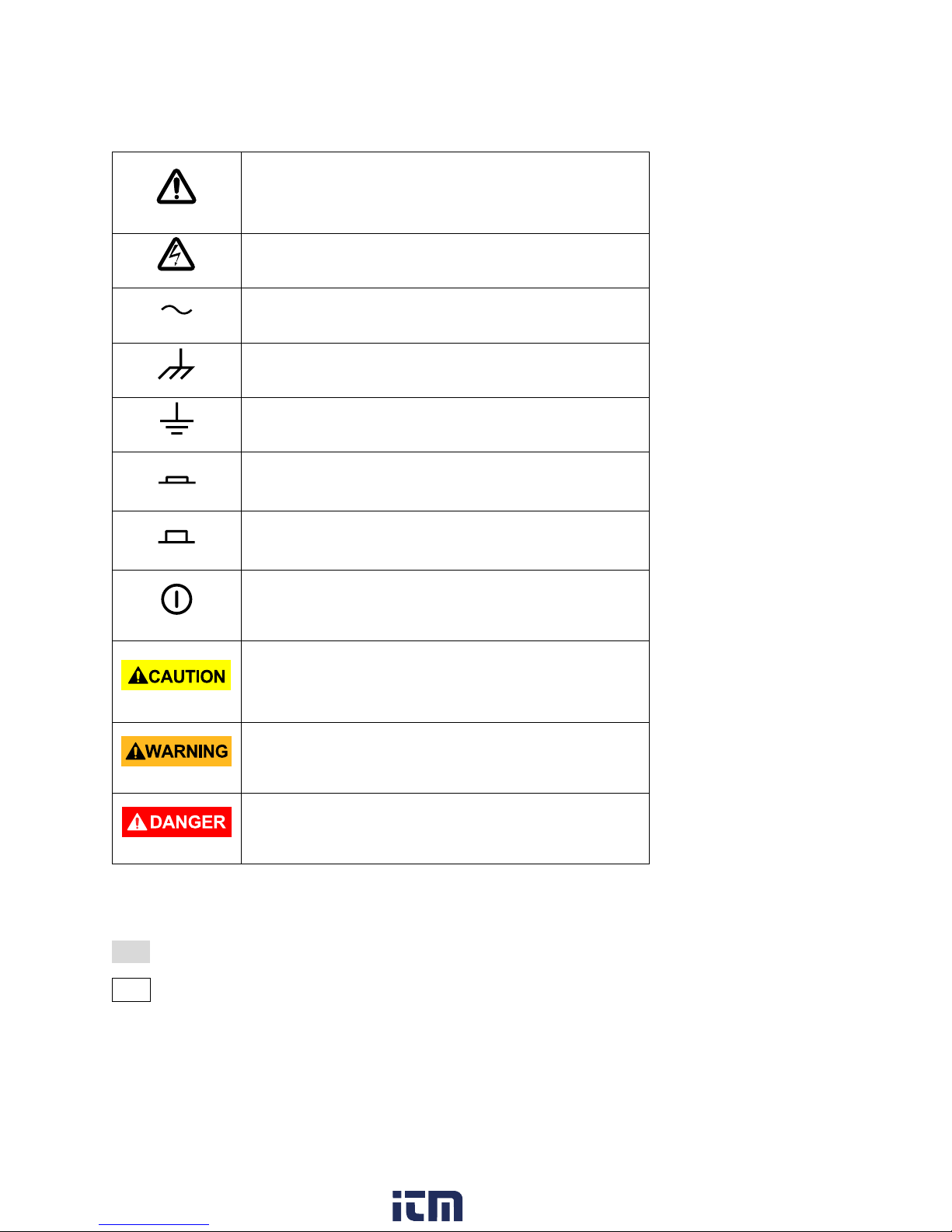
Safety Symbols
Refer to the user manual for warning information
to avoid hazard or personal injury and prevent
damage to instrument.
Electric Shock hazard
Alternating current (AC)
Chassis (earth ground) symbol.
Ground terminal
On (Power). This is the In position of the power
switch when instrument is ON.
Off (Power). This is the Out position of the power
switch when instrument is OFF.
Power Switch (On/Off). This is the power switch
located in front of the instrument.
CAUTION indicates a hazardous situation which, if
not avoided, will result in minor or moderate
injury.
WARNING indicates a hazardous situation which, if
not avoided, could result in death or serious injury.
DANGER indicates a hazardous situation which, if
not avoided, will result in death or serious injury.
Notations
TEXT – Denotes a softkey.
TEXT – Denotes a front panel button.
[TEXT] – Denotes a physical connector in the front or rear panel.
www. .com
ix
information@itm.com1.800.561.8187
Page 11

Table of Contents
SAFETY SUMMARY .................................................................................................................................................. I
COMPLIANCE STATEMENTS ............................................................................................................................................ VII
SAFETY SYMBOLS .......................................................................................................................................................... IX
NOTATIONS ................................................................................................................................................................. IX
1 GENERAL INFORMATION .......................................................................................................................... 1
1.1 PRODUCT OVERVIEW ............................................................................................................................................ 1
1.2 PACKAGE CONTENTS ............................................................................................................................................. 1
1.3 FRONT PANEL OVERVIEW ...................................................................................................................................... 3
Front Panel Description ................................................................................................................................... 3
1.4 REAR PANEL OVERVIEW ........................................................................................................................................ 4
Rear Panel Description .................................................................................................................................... 4
1.5 DISPLAY OVERVIEW .............................................................................................................................................. 5
Display Description .......................................................................................................................................... 5
2 GETTING STARTED .................................................................................................................................... 6
2.1 INPUT POWER REQUIREMENTS ............................................................................................................................... 6
Input Power ..................................................................................................................................................... 6
2.2 OUTPUT CONNECTIONS ......................................................................................................................................... 6
Impedance Matching ....................................................................................................................................... 7
2.3 PRELIMINARY CHECK ............................................................................................................................................. 7
Check Model and Firmware Version ................................................................................................................ 8
Output Check ................................................................................................................................................... 9
3 FRONT PANEL OPERATION ..................................................................................................................... 11
3.1 MENU OPTIONS ................................................................................................................................................. 11
3.2 SELECTING A CHANNEL ........................................................................................................................................ 14
3.3 CONFIGURE WAVEFORM OUTPUT ......................................................................................................................... 15
Configure Waveform Shape .......................................................................................................................... 15
Configure Frequency ...................................................................................................................................... 17
Configure Amplitude ...................................................................................................................................... 18
User-Defined High and Low Level ............................................................................................................................. 19
Configure Offset ............................................................................................................................................ 19
Configure Phase ............................................................................................................................................. 20
Configure Duty Cycle: Square Waveform ...................................................................................................... 21
Configure Width and Duty Cycle: Pulse Waveform ....................................................................................... 22
Configure Rise/Fall Edge: Pulse Waveform ................................................................................................... 23
Configure Delay: Pulse Waveform ................................................................................................................. 24
Configure Symmetry: Ramp Waveform ......................................................................................................... 25
Configure Standard Deviation and Mean: Noise Waveform ........................................................................ 26
Configure Offset: DC Waveform .................................................................................................................... 27
Configure Arbitrary Waveforms .................................................................................................................... 28
Generate Predefined Built-in Waveforms ................................................................................................................. 28
Generate User-Defined Waveforms .......................................................................................................................... 36
Configure Harmonic Generator ..................................................................................................................... 38
3.4 CONFIGURE MODULATION OUTPUT ....................................................................................................................... 40
AM Modulation ............................................................................................................................................. 41
x
www. .com
information@itm.com1.800.561.8187
Page 12

Selecting Modulation Source .................................................................................................................................... 43
To Set Modulation Depth .......................................................................................................................................... 44
To Set Modulation Frequency ................................................................................................................................... 44
DSB-AM Modulation ...................................................................................................................................... 44
FM Modulation .............................................................................................................................................. 46
To Set Frequency Deviation ...................................................................................................................................... 47
PM (Phase Modulation) ................................................................................................................................. 47
To Set Phase Deviation .............................................................................................................................................. 48
FSK Modulation ............................................................................................................................................. 48
To Set Key Frequency ................................................................................................................................................ 49
To Set Hop Frequency ............................................................................................................................................... 50
ASK Modulation ............................................................................................................................................. 50
PSK Modulation ............................................................................................................................................. 51
PWM (Pulse Width Modulation).................................................................................................................... 52
To Set Pulse Width/Duty Deviation ........................................................................................................................... 53
3.5 CONFIGURE SWEEP OUTPUT ................................................................................................................................. 55
Sweep time .................................................................................................................................................... 56
Sweep Frequency ........................................................................................................................................... 56
Sweep Trigger Source .................................................................................................................................... 56
Trig out .......................................................................................................................................................... 57
Sweep Type .................................................................................................................................................... 58
Direction ........................................................................................................................................................ 59
3.6 CONFIGURE BURST ............................................................................................................................................. 59
N-Cycle ........................................................................................................................................................... 60
Cycles ........................................................................................................................................................................ 61
Infinite ....................................................................................................................................................................... 61
Gated ............................................................................................................................................................. 62
Common Settings for NCycle and Gated Burst: ............................................................................................. 63
Start Phase ................................................................................................................................................................ 63
Burst Period .............................................................................................................................................................. 63
Trig Delay .................................................................................................................................................................. 63
Burst Trigger Source .................................................................................................................................................. 64
4 UTILITY FUNCTIONS ............................................................................................................................... 65
4.1 SYSTEM SETTINGS............................................................................................................................................... 66
Numerical Format.......................................................................................................................................... 67
Language Setup ............................................................................................................................................. 68
Power On ....................................................................................................................................................... 68
Set to Default ................................................................................................................................................. 69
Key Sound (Beeper)........................................................................................................................................ 70
Screen Saver .................................................................................................................................................. 70
System Info .................................................................................................................................................... 70
Firmware Update........................................................................................................................................... 71
Built-in Help ................................................................................................................................................... 72
4.2 TEST/CAL ......................................................................................................................................................... 73
ScrTest ........................................................................................................................................................... 73
Key Test ......................................................................................................................................................... 74
LED Test ......................................................................................................................................................... 74
Board Test ..................................................................................................................................................... 75
4.3 FREQUENCY COUNTER ......................................................................................................................................... 75
xi
www. .com
information@itm.com1.800.561.8187
Page 13

4.4 OUTPUT ........................................................................................................................................................... 77
Load ............................................................................................................................................................... 78
Polarity .......................................................................................................................................................... 78
EqPhase ......................................................................................................................................................... 79
Combining Waveforms (Wave Combine) ...................................................................................................... 79
4.5 CH COPY/COUPLING .......................................................................................................................................... 80
Channel Copy ................................................................................................................................................. 80
Channel Coupling ........................................................................................................................................... 81
Frequency Coupling .................................................................................................................................................. 82
Amplitude Coupling .................................................................................................................................................. 82
Phase Coupling .......................................................................................................................................................... 83
Tracking ......................................................................................................................................................... 83
4.6 REMOTE INTERFACE ............................................................................................................................................ 85
USB Interface ................................................................................................................................................. 86
GPIB Interface ................................................................................................................................................ 86
LAN ................................................................................................................................................................ 88
To Set IP Address....................................................................................................................................................... 88
To Set Subnet Mask .................................................................................................................................................. 89
To Set Gateway ......................................................................................................................................................... 89
DHCP Configuration Mode ........................................................................................................................................ 89
4.7 SYNC OUTPUT ................................................................................................................................................... 90
Syncing Signals of Different Waveforms ....................................................................................................... 91
Basic Waveform and Arbitrary Waveform ................................................................................................................ 91
Modulated Waveform ............................................................................................................................................... 91
4.8 REFERENCE CLOCK .............................................................................................................................................. 91
Sync methods for two or more instruments: ................................................................................................. 92
Synchronization between two instruments .............................................................................................................. 92
Synchronization among multiple instruments .......................................................................................................... 92
4.9 MODE .............................................................................................................................................................. 92
4.10 OVER VOLTAGE PROTECTION ................................................................................................................................ 94
5 STORE AND RECALL ................................................................................................................................ 95
5.1 STORAGE SYSTEM ............................................................................................................................................... 96
Local (C:) ........................................................................................................................................................ 96
USB Device (0:) .............................................................................................................................................. 96
Browse ........................................................................................................................................................... 97
5.2 FILE TYPE .......................................................................................................................................................... 97
5.3 SAVE THE INSTRUMENT STATE .............................................................................................................................. 98
5.4 RECALL STATE FILE OR DATA FILE ........................................................................................................................ 100
5.5 DELETE FILE .................................................................................................................................................... 100
5.6 COPY AND PASTE FILE ....................................................................................................................................... 100
6 EXAMPLES ............................................................................................................................................ 102
Example 1: Generate a Sine Waveform ....................................................................................................... 103
Example 2: Generate a Square Waveform .................................................................................................. 104
Example 3: Generate a Ramp Waveform .................................................................................................... 105
Example 4: Generate a Pulse Waveform ..................................................................................................... 106
Example 5: Generate a Noise ...................................................................................................................... 107
Example 6: Generate a DC Waveform ......................................................................................................... 108
Example 7: Generate a Linear Sweep Waveform ........................................................................................ 109
xii
www. .com
information@itm.com1.800.561.8187
Page 14

Example 8: Generate a Burst Waveform ..................................................................................................... 110
Example 9: Generate an AM Modulation Waveform .................................................................................. 112
Example 10: Generate an FM Modulation Waveform ................................................................................ 113
Example 11: Generate a PM Modulated Waveform ................................................................................... 114
Example 12: Generate an FSK Modulated Waveform ................................................................................. 115
Example 13: Generate an ASK Modulation Waveform ................................................................................ 116
Example 14: Generate a PSK Modulated Waveform ................................................................................... 117
Example 15: Generate a PWM Modulated Waveform ................................................................................ 118
Example 16: Generate a DSB-AM Modulated Waveform............................................................................ 119
7 TROUBLESHOOTING GUIDE .................................................................................................................. 120
8 SPECIFICATIONS ................................................................................................................................... 121
SERVICE INFORMATION ..................................................................................................................................... 125
LIMITED THREE-YEAR WARRANTY ..................................................................................................................... 126
xiii
www. .com
information@itm.com1.800.561.8187
Page 15

1 General Information
1.1 Product Overview
BK Precision’s 4050B series are dual-channel function/arbitrary waveform generators, capable
of generating sine and square waves of up to 10 MHz, 30 MHz or 60 MHz (depending on
model). They have an informative easy-to-read color display, user-friendly controls and a
numeric keypad which allows users to easily configure waveform properties. These waveform
generators can output square waves with frequencies up to 60 MHz (depending on model) and
less than 300 ps + 0.05 ppm of period of jitter. In addition, they feature non-volatile built-in
memory to create, store, and recall arbitrary waveforms up to 16K points with a 150 MSa/s
sampling rate, and 14-bit vertical resolution. 196 predefined arbitrary waveforms are also
available for output. Having USBTMC, LAN, and GPIB (optional adapter) interfaces, these
generators allow users to easily interface with application software to create and load arbitrary
waveforms into the instrument.
Features:
Dual-channel output with bandwidth up to 10 MHz, 30 MHz or 60 MHz
Amplitude up to 10 Vpp into 50 ohms.
150 MSa/s sampling rate, 14-bit vertical resolution, and 16K points waveform length
Capable of generating low jitter pulse waveforms
Square waves with low jitter and frequencies up to 60 MHz (depending on model)
AM, DSB-AM, FM, PM, FSK, ASK, PSK and PWM modulation functions
Sweep and burst functions
Harmonic waveforms generator
Waveform combining function
High-precision frequency counter
196 built-in arbitrary waveforms
4.3” TFT-LCD display, 480 x 272 resolution
1.2 Package Contents
Please inspect the instrument mechanically and electrically upon receiving it. Unpack all items
from the shipping carton, and check for any obvious signs of physical damage that may have
occurred during transportation. Report any damage to the shipping agent immediately. Save
the original packing carton for possible future reshipment. Every instrument is shipped with the
following contents:
1
www. .com
information@itm.com1.800.561.8187
Page 16

1 x 4050B series function/arbitrary waveform generator
1 x Getting started manual (printed)
1 x AC power cord
1 x USB type A to Type B cable
1 x Certificate of calibration
Verify that all items above are included in the shipping container. If anything is missing, please
contact B&K Precision.
An optional USB to GPIB adapter model AK40G is also available.
2
www. .com
information@itm.com1.800.561.8187
Page 17
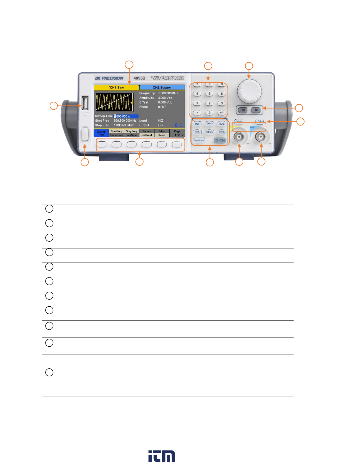
1.3 Front Panel Overview
Power On/Off switch
Menu softkeys
Menu buttons
Channel 1 output terminal
Channel 2 output terminal
Channel 1 and 2 Output On/Off buttons
Arrow keys
Rotary dial knob
Numeric keypad
TFT LCD color display
USB host port/*USB-to-GPIB adapter interface
Accepts USB flash drive to save/recall instrument settings and waveforms.
*This port can be used for connecting the USB-to-GPIB adapter (AK40G)
accessory. It can also be used for connecting an external USB flash drive.
1 2 3 4 5 6 7 8 9
10
11
1
10
2 3 5
6 7 8 9 11
4
Front Panel Description
www. .com
3
information@itm.com1.800.561.8187
Page 18
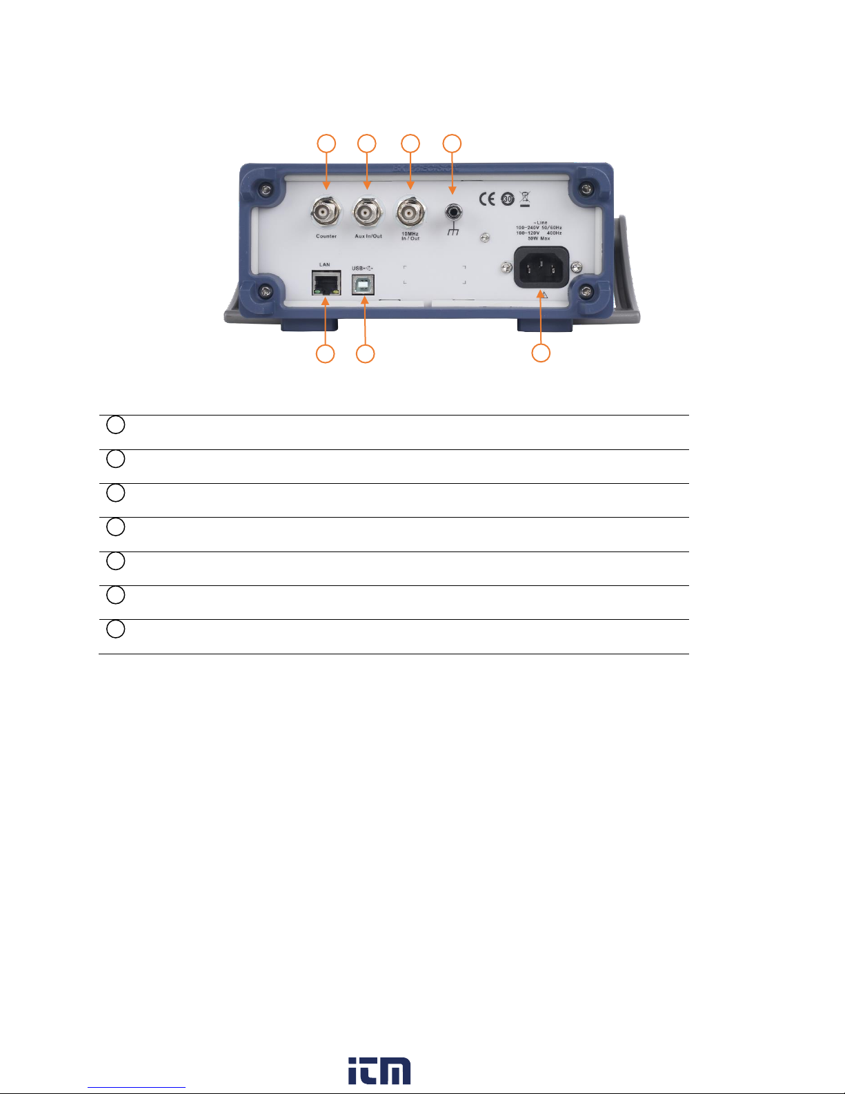
1.4 Rear Panel Overview
LAN Interface
USB interface
AC Power Input
Chassis ground
10MHz Out BNC connector
Aux In/Out BNC connector
Counter BNC Connector
1 2 3
4
5
6
7
1 2 3
4 6 7
5
Rear Panel Description
4
www. .com
information@itm.com1.800.561.8187
Page 19
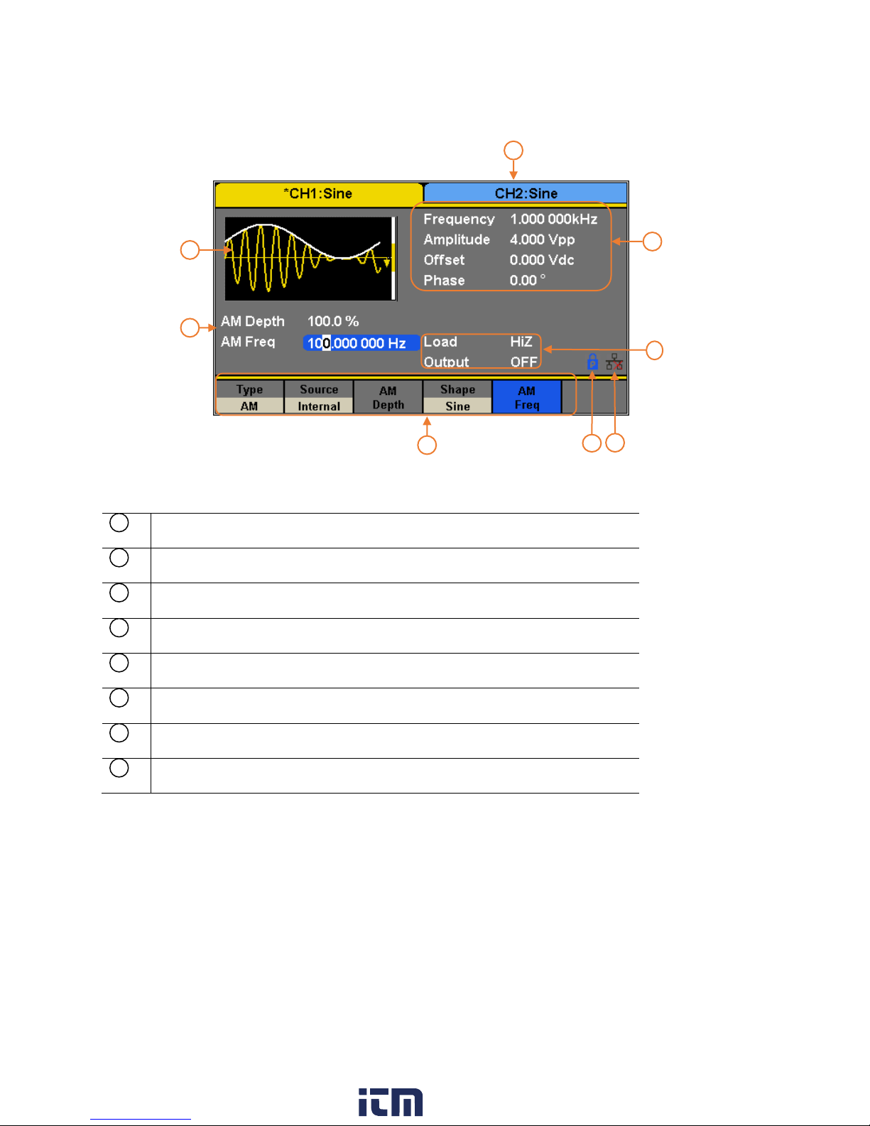
1.5 Display Overview
Waveform display
Channel status bar
Waveform parameters display
Waveform mode and output impedance indicator
LAN status indicator
Mode phase locked/free running indicator
Menu display
Waveform parameters display
1 2 3 4 5 6 7
8
1 7 3
2
5
4
8
Display Description
www. .com
5
information@itm.com1.800.561.8187
Page 20

2 Getting Started
The included AC power cord is safety certified for this instrument operating in rated
range. To change a cable or add an extension cable, be sure that it can meet the
required power ratings for this instrument. Any misuse with wrong or unsafe cables
will void the warranty.
Before connecting and powering up the instrument, please review and go through the
instructions in this chapter.
2.1 Input Power Requirements
Input Power
The supply has a universal AC input that accepts line voltage and frequency input within:
100 – 240 V (+/- 10%), 50 – 60 Hz (+/- 5%)
100 – 127 V, 45 – 440 Hz
Before connecting to an AC outlet or external power source, be sure that the power switch is in
the OFF position and verify that the AC power cord, including the extension line, is compatible
with the rated voltage/current and that there is sufficient circuit capacity for the power supply.
Once verified, connect the cable firmly.
2.2 Output Connections
The waveform generator output circuits operate as a 50 Ω voltage source working into a 50 Ω
load. At higher frequencies, a non-terminated or improperly terminated output may cause
aberrations on the output waveform. In addition, loads with an impedance less than 50 Ω will
reduce the waveform amplitude, while loads with an impedance greater than 50 Ω will increase
waveform amplitude.
Excessive distortion or aberrations caused by improper termination are less noticeable at lower
frequencies, especially with sine and triangle waveforms. To ensure waveform integrity, follow
these precautions:
www. .com
6
information@itm.com1.800.561.8187
Page 21

1. Use good quality 50 Ω coaxial cable and connectors.
2. Make all connections tight and as short as possible.
3. Use good quality attenuators, if it is necessary to reduce waveform amplitudes applied
to sensitive circuits.
4. Use termination or impedance-matching devices to avoid reflections.
5. Ensure that attenuators and terminations have adequate power handling capabilities.
If there is a DC voltage across the output load, use a coupling capacitor in series with the load.
The time constant of the coupling capacitor and load must be long enough to maintain pulse
flatness.
Impedance Matching
If the waveform generator is driving a high impedance, such as a 1 MΩ input impedance
(paralleled by a stated capacitance) of an oscilloscope vertical input, connect the transmission
line to a 50 Ω attenuator, a 50 Ω termination and to the oscilloscope input. The attenuator
isolates the input capacitance of the device and terminates the waveform generator properly.
2.3 Preliminary Check
Complete the following steps to verify that the generator is ready for use.
1. Verify AC Input Voltage
Verify and check to make sure proper AC voltages are available to power the
instrument. The AC voltage range must meet the acceptable specification as explained
in section 2.1.
2. Connect Power
Connect AC power cord to the AC receptacle in the rear panel and press the power
switch to the ON position to turn ON the instrument. The instrument will have a boot
screen while loading, after which the main screen will be displayed.
3. Self Test
Press Utility, and select Test/Cal option. Then, select SelfTest option. The instrument
has 4 self-test options: screen test, key test, LED test, and board test.
7
www. .com
information@itm.com1.800.561.8187
Page 22
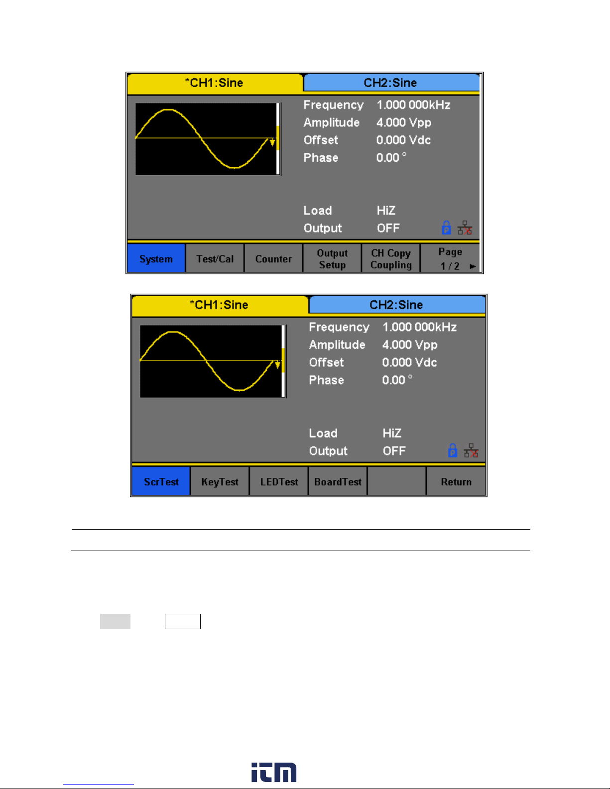
Figure 1 - Preliminary Self-Test
Figure 2 - Self-Test Options
Note: Refer to TEST/CAL section for more information about the Self-Test function.
Check Model and Firmware Version
The model and firmware version can be verified from within the menu system.
Press Utility, press System select and press Page 1/2 from the menu to enter the second menu
page, and select System Info option. The software/firmware version, hardware version, model,
and serial number will be displayed. Press any Menu Softkey key to exit.
8
www. .com
information@itm.com1.800.561.8187
Page 23

Output Check
Output
Default
Function
Sine Wave
Frequency
1 kHz
Amplitude/Offset
4 Vpp/0 Vdc
Phase
0°
Load
High Z
Modulation
Default
Carrier
1 kHz Sine wave
Modulating
100 Hz Sine wave
AM Depth
100%
FM Deviation
100 Hz
ASK Key Frequency
100 Hz
FSK Key Frequency
100 Hz
FSK Hop Frequency
1 MHz
PSK Key Frequency
10 0Hz
PM Phase Deviation
100°
PWM Width Dev
190 μs
Sweep
Default
Start/Stop Frequency
500 Hz/1.5 kHz
Sweep Time
1 s
Trig Out
Off
Mode
Linear
Direction
↑
Burst
Default
Burst Period
10 ms
Follow the steps below to do a quick check of the settings and waveform output.
1. Turn on the instrument and set the instrument to default settings. To set to default,
press Utility → System → Set To Default to set the system to the default setting. The
instrument will set both channels with the following parameters:
9
www. .com
information@itm.com1.800.561.8187
Page 24

Start Phase
0°
Cycles
1 Cycle
Trig Out
Off
Delay
521 ns
Trigger
Default
Source
Internal
Table 1 - Default Settings
1. Connect the BNC output of CH1 (yellow) into an oscilloscope.
2. Press the Output button on top of CH1 output BNC to turn on the output and observe a
sine wave with the parameters above.
3. Press the Parameter button.
4. Press Freq or Period option in the menu and use the rotary knob or the numeric keypad
to change frequency. Observe the changes on the oscilloscope display.
5. Press the Amplitude option in the menu and use the rotary knob or the numeric keypad
to change the amplitude. Observe the changes on the oscilloscope display.
Press the Offset option in the menu and use the rotary knob or the numeric keypad to
change the DC offset. With the oscilloscope set for DC coupling, observe the changes on
the display.
Connect the BNC output of CH2 (blue) into an oscilloscope and follow steps 3 to 6 to
check its output. Use the Ch1/Ch2 to toggle between channels.
10
www. .com
information@itm.com1.800.561.8187
Page 25
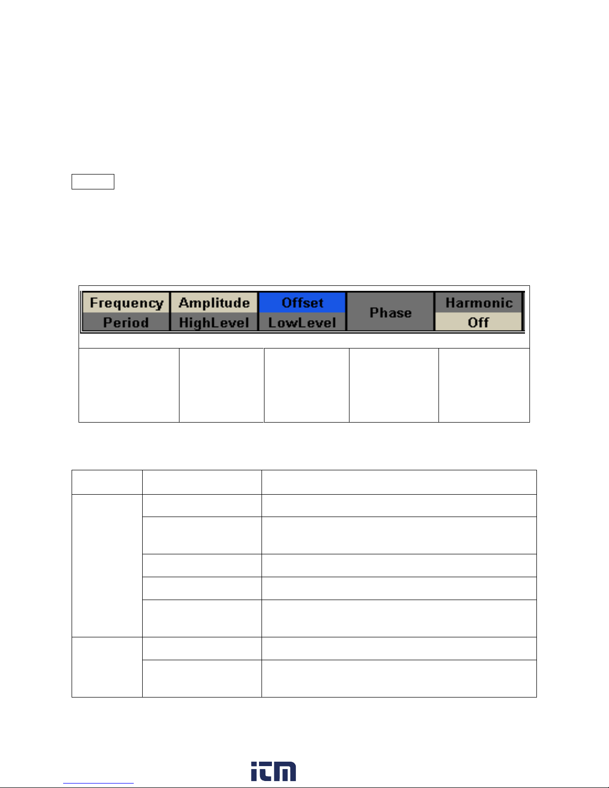
3 Front Panel Operation
Softkey will toggle
selection between
Frequency or Period.
Softkey will toggle
selection
between
Amplitude or
HighLevel.
Softkey will toggle
selection
between Offset or
LowLevel.
Softkey will select
Phase.
Softkey will enable
or disable the
Harmonic
Generation
Function.
Waveforms
Parameter
Function
Sine
Frequency/Period
Configures the frequency or period of the waveform.
Amplitude/HighLevel
Configures the amplitude or the high level of the
waveform.
Offset/LowLevel
Configures the DC offset or the low level of the waveform.
Phase
Configures the phase relative to the other channel.
Harmonic/Off
Turns Harmonics Generator on or off. See Harmonics
Generator section.
Square
Frequency/Period
Configures the frequency or period of the waveform.
Amplitude/HighLevel
Configures the amplitude or the high level of the
waveform.
Table 2 - Menu Options Softkeys
3.1 Menu Options
All settings and parameters can be configured from the menu system of the instrument. The
channel specific menu options are the same for both channel 1 and channel 2. Use the
Ch1/Ch2 button keys to toggle the channel selection. The selected option will be highlighted in
blue. Some settings are common for most waveforms (i.e. frequency, amplitude, offset, etc.)
and some are specific to each type of waveform (i.e. Duty cycle only available for square and
pulse waveforms). Section 3.3 provides instructions on how to configure these settings.
Many options are grouped in pairs and can be selected by toggling their corresponding menu
function keys. For example:
The menu system is organized as follows:
www. .com
11
information@itm.com1.800.561.8187
Page 26

Offset/LowLevel
Configures the DC offset or the low level of the waveform.
Phase
Configures the phase relative to the other channel.
DutyCycle
Configures the duty cycle of the waveform.
Ramp
Frequency/Period
Configures the frequency or period of the waveform.
Amplitude/HighLevel
Configures the amplitude or the high level of the
waveform.
Offset/LowLevel
Configures the DC offset or the low level of the waveform.
Phase
Configures the phase relative to the other channel.
Symmetry
Configures the symmetry of the waveform.
Pulse
Frequency/Period
Configures the frequency or period of the waveform.
Amplitude/HighLevel
Configures the amplitude or the high level of the
waveform.
Offset/LowLevel
Configures the DC offset or the low level of the waveform.
PulWidth/DutyCycle
Configures the pulse width or the duty cycle of the pulse.
Rise/Fall
Configures the rise or fall time of the pulse.
Delay
Configures the delay of the pulse waveform.
Noise
Stdev
Configures the standard deviation of the noise waveform.
Mean
Configures the mean value of the noise waveform.
DC
DC Offset
Configures the DC offset of the DC waveform.
Arb
Frequency/Period
Configures the frequency or period of the waveform.
Amplitude/HighLevel
Configures the amplitude or the high level of the
waveform.
Offset/LowLevel
Configures the DC offset or the low level of the waveform.
Phase
Configures the phase relative to the other channel.
Arb Type
Access selectable built-in arbitrary waveforms and userdefined arbitrary waveform stored in the generator.
Mod
Type
Configures the type of modulation. Configures parameters
for AM, FM, PM, ASK, FSK, DSB-AM, or PWM modulation.
www. .com
12
information@itm.com1.800.561.8187
Page 27

Source
Selects modulating source.
AM Depth
Set the modulation depth.
Shape
Configures the modulating waveform shape.
AM Freq
Set the modulating waveform frequency. Frequency range:
1 mHz to 20 kHz (internal source only).
Sweep
Sweep Time
Configures the sweep time for sweep output.
StartFreq/CenterFReq
Configures the sweep start frequency or the center
frequency.
StopFreq/FreqSpan
Configures the sweep stop frequency or the frequency
span of the sweep output.
Source
Selects the sweep source: Internal, external or manual.
Trig Out
Enable/disable trigger out.
Type
Selects between linear or logarithmic sweep operations.
Direction
Selects the sweep direction.
Burst
Ncycle/Gated
Selects burst by number of cycles or selects external gated
burst.
Cycles/Infinite
Configures number of cycles for burst or infinite burst
(external source only).
Start Phase
Configures the start phase of the burst output.
Burst Period
Configures the burst period.
Source
Selects trigger source: Internal, External, Manual.
Trig Delay
Configures the delay of each burst.
Trig Out
Configures signal triggering on rising or falling edge.
Utility
System
Access system settings.
Test/Cal
Configure synchronization output with respect to either
channel 1 or 2.
Counter
Selects built-in counter function.
www. .com
13
information@itm.com1.800.561.8187
Page 28
Output Setup
Set the output parameters of CH1 and CH2.
CH Copy Coupling
Set the track, channel coupling or channel copy function.
Interface
Select and set parameters of remote communication.
Clock
Choose the system clock source: internal or external.
Mode
Choose Phase-locked or independent mode.
OverVoltage Protection
Turn on/off the overvoltage protection function.
CHCopy
Copy channel settings between channels.
Table 3 - Menu System Organization
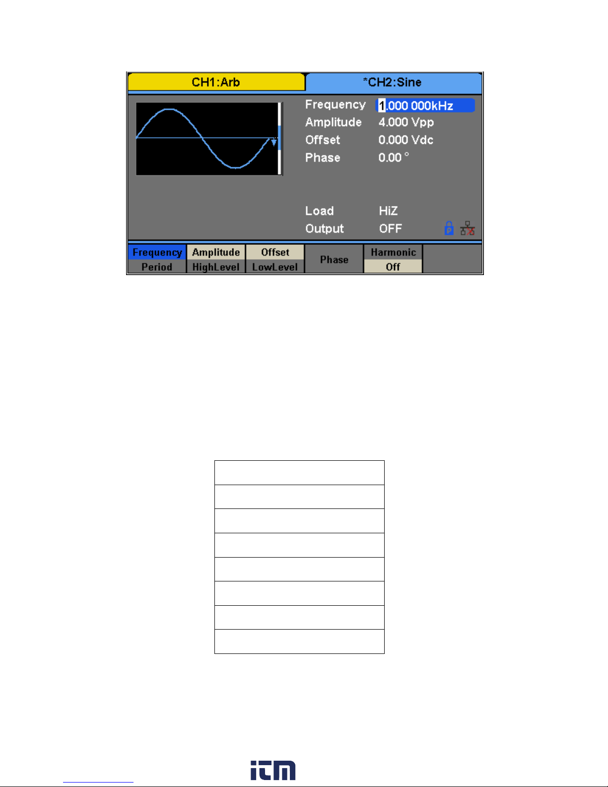
Figure 3 – Channel 1 Selected
3.2 Selecting a Channel
The 4050B series function/arbitrary waveform generators have dual channel outputs. They can
be operated independently or in sync with each other. To select between channel 1 and 2 and
view/change their parameters, press the Ch1/Ch2 key.
When Channel 1 is selected, the display will look like the following:
When Channel 2 is selected, the display will look like the following:
www. .com
14
information@itm.com1.800.561.8187
Page 29
Waveforms
Sine
Square
Ramp
Pulse
Noise
DC
Arbitrary
Figure 4 - Channel 2 Selected
Table 4 - Waveforms
3.3 Configure Waveform Output
Configure Waveform Shape
The instrument can generate many standard as well as arbitrary waveforms. There is a
dedicated waveform key on the front panel that will allow the user to select between different
waveform shapes to output, as listed in Table 4.
15
www. .com
information@itm.com1.800.561.8187
Page 30
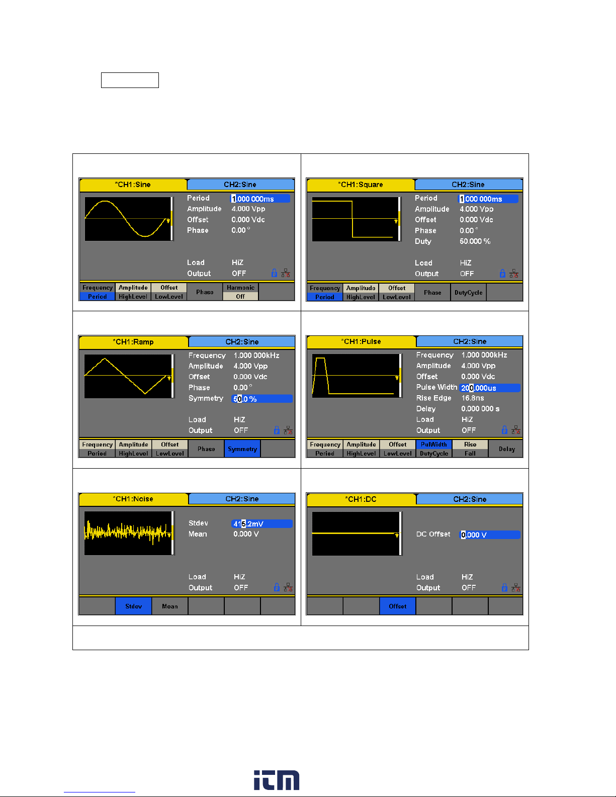
Press Waveforms to select a waveform. Menu options relevant to the selected waveform
Sine Waveform
Square Waveform
Ramp Waveform
Pulse Waveform
Noise Waveform
DC Waveform
Arbitrary Waveform
shape will display at the bottom of the screen. The screenshots below illustrates the menu
options for each of the waveform types.
16
www. .com
information@itm.com1.800.561.8187
Page 31
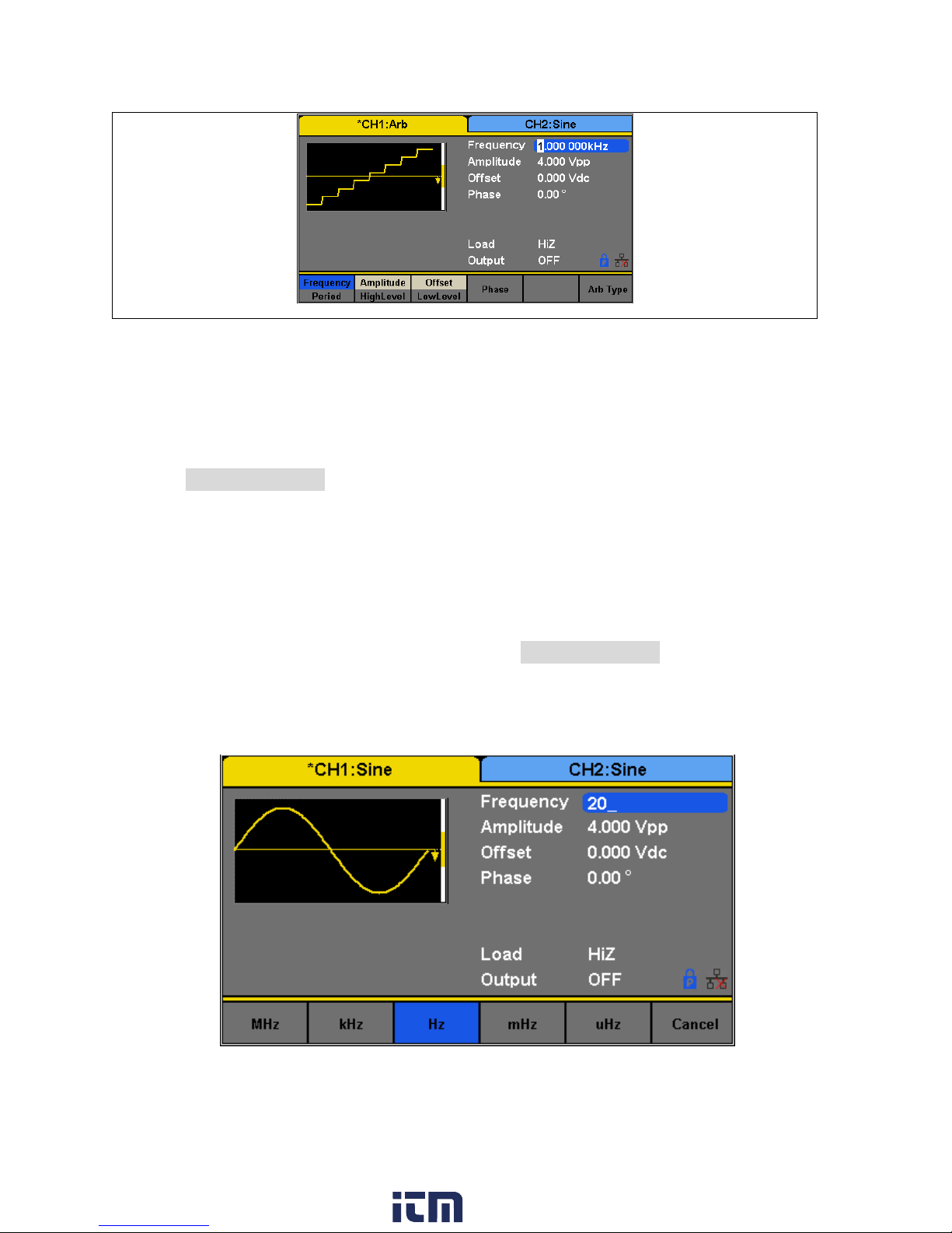
Table 5 - Waveforms
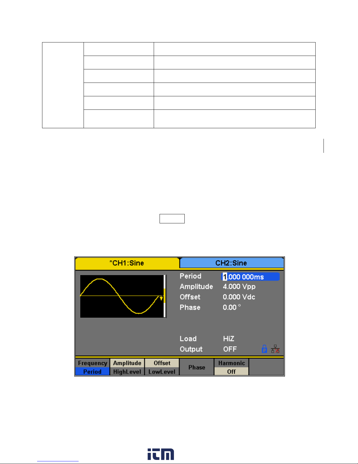
Figure 5 - Frequency
Configure Frequency
This section does not apply to noise or DC waveforms.
Press the Frequency/Period softkey to toggle between the Frequency and Period settings. The
option selected will be highlighted in blue. The current value for the waveform’s frequency or
period is now highlighted on the Waveform Parameters display section of the screen.
The adjustable frequency range is different for each model and for each type of waveforms.
See the specifications sheet section for the adjustable ranges.
Follow the steps below to configure the frequency or period of the output:
1. After selecting the waveform shape, press the Frequency/Period menu option.
2. The cursor position will now highlight the first digit of the frequency parameter display.
3. Use the rotary knob or the numeric keypad to change the frequency. If numeric keypad
is used, the following screen will be displayed after entering a numeric value:
17
www. .com
information@itm.com1.800.561.8187
Page 32
4. Use the menu function keys to select the unit. Available units are: MHz, kHz, Hz, mHz,
Note: When using the numeric keyboard to enter the value, the left arrow key can be used to move the
cursor backward and delete the previous digit.
Figure 6 - Amplitude
and uHz.
Configure Amplitude
This section does not apply for noise or DC waveform. The amplitude setting range is limited by
the load and frequency, as shown below:
2 mVpp – 10 Vpp into 50 Ω (4 mVpp – 20 Vpp into open circuit), ≤ 10 MHz
2 mVpp – 5 Vpp into 50 Ω (4 mVpp – 10 Vpp into open circuit), > 10 MHz
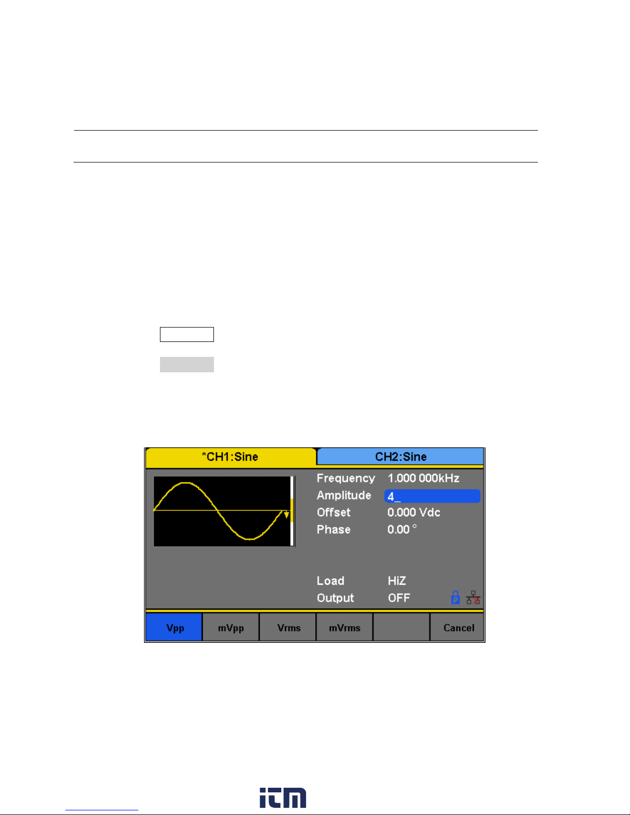
Follow the steps below to configure the amplitude of the output:
1. Press the Waveforms button.
2. Select a waveform from the menu.
3. Press the Amplitude softkey. The cursor position now highlights the first digit of the
amplitude parameter display.
4. Use the rotary knob or the numeric keypad to change the amplitude.
a. If numeric keypad is used, the following screen will be displayed after entering a
number:
5. Use the menu function keys to select the unit. Available units are: Vpp, mVpp, Vrms,
and mVrms.
18
www. .com
information@itm.com1.800.561.8187
Page 33

Figure 7 - Amplitude: High and Low Level
Note: DC offset settings will be automatically adjusted if the high and low levels reflect a DC offset.
User-Defined High and Low Level
The user has the option to adjust the high and low level of the waveform. To do this, toggle the
menu function key from Amplitude to HighLevel and the LowLevel option will be available as
well.
Configure Offset
This section does not apply to noise waveform.The offset setting range is limited by the “Load”
and “Amplitude/HighLevel” settings. The range is: ± 5 V into 50 Ω (± 10 V into open circuit). The
default value is 0 Vdc.
Follow the steps below to configure the DC offset of the output:
1. Press the Waveforms button.
2. Select a waveform from the menu.
3. Press the Offset softkey.
4. The cursor position now highlights the first digit of the offset parameter display.
5. Use the rotary knob or the numeric keypad to change the offset. If numeric keypad is
used, the following screen will be displayed after entering a number:
19
www. .com
information@itm.com1.800.561.8187
Page 34

Figure 8 - Offset
6. Use the menu function keys to select the unit. Available units are: Vdc and mVdc.
Configure Phase
This section does not apply for pulse, noise, or DC waveforms.
The Phase setting is useful for adjusting the phase relationship between channels 1 and 2,
between a channel and its sync signal, and synchronizing multiple instruments. This setting is
different from the Start Phase in Burst mode.
Follow the steps below to configure the phase of the output:
1. Press the Waveforms button.
2. Select a waveform from the menu.
3. Press the Phase softkey.
4. The cursor position now highlights the first digit of the phase parameter display.
5. Use the rotary knob or the numeric keypad to change the phase. If numeric keypad is
used, the following screen will be displayed after entering a number:
20
www. .com
information@itm.com1.800.561.8187
Page 35

Figure 9 - Phase
Note: When the IndependentMode is enabled, the phase parameter cannot be modified (i.e., the phase
can only be set when there is a reference clock waveform provided on the back panel).
Figure 10 - Duty Cycle
6. Use the menu function keys to select the degree (°) unit.
Configure Duty Cycle: Square Waveform
The duty cycle setting range is limited by the “Frequency/Period” setting. The default value is
50%.
Follow the steps below to configure the phase of the output:
1. Press the Waveforms button and select the Square waveform.
2. Press the DutyCycle softkey and input the desired duty cycle.
3. Use the rotary knob or the numeric keypad to change the duty cycle. If numeric keypad
is used, the following screen will be displayed after entering a number:
21
www. .com
information@itm.com1.800.561.8187
Page 36

Note: The instrument allows for adjusting pulse width to a minimum of 32.6 ns, depending on frequency.
Figure 11 - Duty Cycle of a Square Waveform
Figure 12 - Pulse Width and Period
4. Use the menu function keys to select the degree (°) unit.
Configure Width and Duty Cycle: Pulse Waveform
The pulse width and duty cycle parameters are related to each other and both control the
length of the “On Time” of a pulse. Users have the option to specify the pulse width in units of
seconds or the duty cycle as a percentage. Pulse duty cycle and pulse width are dependent—
changing one of the parameters will automatically change the other.
22
www. .com
information@itm.com1.800.561.8187
Page 37

Follow the steps below to configure the pulse width or duty cycle.
Figure 13 - Pulse Width or Duty Cycle
Figure 14 - Pulse Width
1. Press the Waveforms button.
2. Press the Pulse softkey.
3. Select PulWidth softkey for pulse width adjustment or DutyCycle for duty cycle
adjustment.
4. The cursor position will now highlight the first digit of the width or duty parameter
display.
5. Use the rotary knob or the numeric keypad to change the width or the duty.
After entering the numeric value, use the menu function keys to select s, ms, us, or ns
for pulse width or select percent (%) unit for duty cycle.
Configure Rise/Fall Edge: Pulse Waveform
Follow the below steps to setup rise and fall time.
1. Press the Waveforms button.
2. Press the Pulse softkey.
23
www. .com
information@itm.com1.800.561.8187
Page 38

3. Toggle the Rise/Fall softkey to set the rise or fall edge.
Figure 15 - Rise Edge of a Pulse
The Rise/Fall softkey lets the user toggle between the Rise and Fall Edge settings. The selected
setting will be highlighted in blue.
Use the numeric keyboard to input the parameter value directly and press the corresponding
key to select the parameter unit. Alternatively, use the arrow keys to select the digit and use
the knob to change its value.
Configure Delay: Pulse Waveform
Follow the steps below to configure the pulse delay.
1. Set the instrument for pulse.
2. From the menu, select Delay.
3. The cursor position will now highlight the first digit of the delay parameter display.
24
www. .com
information@itm.com1.800.561.8187
Page 39
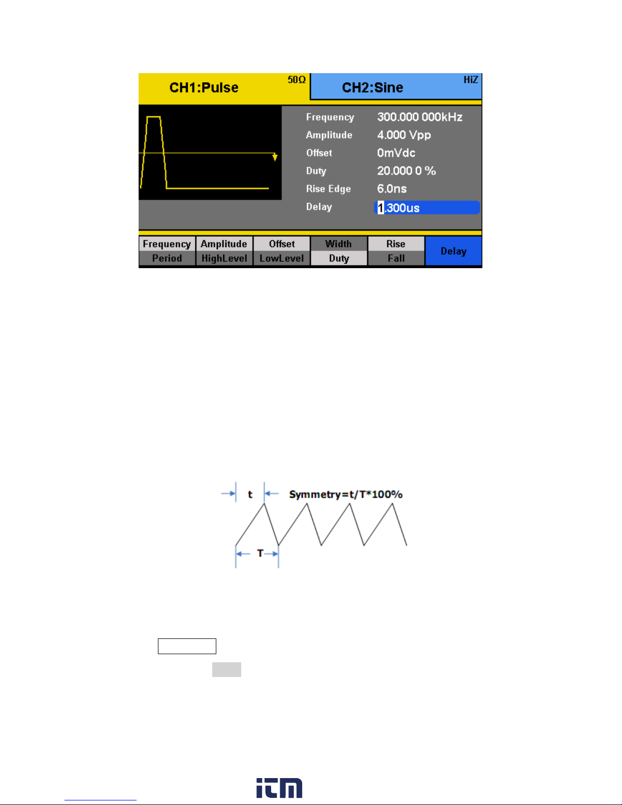
Figure 16 - Pulse Delay
Figure 17 - Symmetry
4. Use the rotary knob or the numeric keypad to change the pulse delay.
After entering the numeric value, use the menu function keys to select s, ms, us, or ns.
Configure Symmetry: Ramp Waveform
A ramp waveform with 50% of symmetry is a triangular waveform. A sawtooth waveform is a
ramp waveform with either 0 or 100 percent.
Follow the steps below to configure the symmetry of a ramp/triangle waveform.
1. Press the Waveforms button.
2. Select and press the Ramp waveform softkey from the menu.
3. The cursor position will now highlight the first digit of the symmetry parameter display.
25
www. .com
information@itm.com1.800.561.8187
Page 40

Figure 18 - Ramp Symmetry
4. Use the rotary knob or the numeric keypad to change the symmetry.
5. Once the value has been entered, press the “%” softkey from the menu to set the value.
Configure Standard Deviation and Mean: Noise Waveform
There are two parameters that can be adjusted of the noise waveform: Standard deviation and
mean. Noise is a non-periodic random signal which has no frequency or period.
Follow the steps below to configure these parameters.
1. Press the Waveforms button.
2. Select and press the Noise waveform softkey from the menu.
3. From the menu, select Stdev for the standard deviation adjustment or Mean for the
mean adjustment.
4. The cursor position will now highlight the first digit of the standard deviation or mean
parameter display.
26
www. .com
information@itm.com1.800.561.8187
Page 41
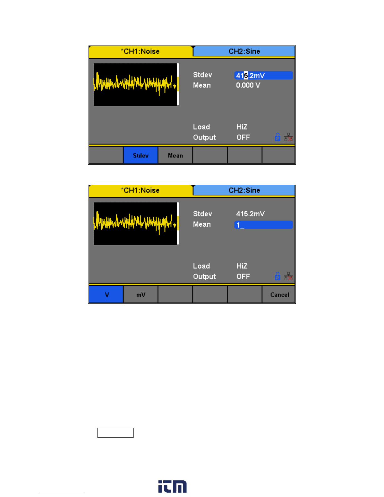
Figure 19 - Noise Standard Deviation
Figure 20 - Noise Mean
5. Use the rotary knob or the numeric keypad to change the two parameters. Both
parameters can be specified in V or mV units.
Configure Offset: DC Waveform
The instrument can output a DC waveform output at a range of voltage levels (-12 Vdc – 12
Vdc).
There is only one parameter, DC Offset, to configure a DC output waveform.
Follow the steps below to configure the parameter.
1. Press the Waveforms button.
27
www. .com
information@itm.com1.800.561.8187
Page 42

2. Select and press the DC waveform softkey from the menu.
Arbitrary Waveform: Common
Figure 21 - DC Offset
3. The cursor position will now be highlighted the first digit of the DC offset parameter
display.
4. Use the rotary knob or the numeric keypad to change the two parameters. Both
parameters can be specified in Vdc or mVdc units.
Configure Arbitrary Waveforms
There are two ways to generate arbitrary waveforms. Users can output a predefined arbitrary
waveform that is built-in, or create and output a user-defined waveform by specifying point by
point arbitrary data using the EasyWave software. Waveforms can be stored in the internal
non-volatile memory. The methods of setting the parameters of an arbitrary waveform signal
are similar to those of the sine waveform function.
Generate Predefined Built-in Waveforms
There are a total of 196 predefined built-in arbitrary waveforms that can output from the
generator. They are divided in the following categories:
28
www. .com
information@itm.com1.800.561.8187
Page 43

Waveform
Function
Waveform
Function
StairUp
Stair-up waveform
Npulse
Negative pulse
StairDn
Stair-down waveform
UpRamp
UpRamp waveform
StairUD
Stair-up and down
waveform
DnRamp
DnRamp waveform
Trapezia
Trapezia waveform
SineTra
Sine-Tra waveform
Ppulse
Positive pulse
SineVer
Sine-Ver waveform
Arbitrary Waveform: Math
Waveform
Function
Waveform
Function
ExpFall
ExpFall function
Legend
5-times Legend polynomial
ExpRise
ExpRise function
Versiera
Versiera
LogFall
LogFall function
Sinc
Sinc function
LogRise
LogRise function
Gaussian
Gaussian function
Sqrt
Sqrt function
Dlorentz
Dlorentz function
Root3
Root3 function
Haversine
Haversine function
X^2
X2 function
Lorentz
Lorentz function
X^3
X3 function
Gauspuls
Gauspuls signal
Airy
Airy function
Gmonopuls
Gmonopuls signal
Besselj
Bessel I function
Tripuls
Tripuls signal
Bessely
Bessel II function
Weibull
Weibull distribution
Dirichlet
Dirichlet function
LogNormal
LogNormal Gaussian
distribution
Erf
Error function
Laplace
Laplace distribution
Erfc
Complementary error
function
Maxwell
Maxwell distribution
ErfcInv
Inverted complementary
error function
Rayleigh
Rayleigh distribution
ErfInv
Inverted error function
Cauchy
Cauchy distribution
Laguerre
4-times Laguerre
polynomial
29
www. .com
information@itm.com1.800.561.8187
Page 44

Arbitrary Waveform: Engine
Waveform
Function
Waveform
Function
Cardiac
Cardiac signal
SCR
SCR firing profile
Quake
Analog quake waveform
TV
TV signal
Chirp
Chirp signal
Voice
Voice signal
TwoTone
TwoTone signal
Surge
Surge signal
SNR
SNR signal
Radar
Analog radar signal
AmpALT
Gain oscillation curve
Ripple
Ripple wave of battery
AttALT
Attenuation oscillation
curve
Gamma
Gamma signal
RoundHalf
RoundHalf Waveform
StepResp
Step-response signal
RoundsPM
RoundsPM Waveform
BandLimited
Bandwidth-limited signal
BlaseiWave
Time-velocity curve of
explosive oscillation
CPulse
C-Pulse
DampedOsc
Time-displacement curve of
damped oscillation
CWPulse
CW pulse
SwingOsc
Kinetic energy – time curve
of swing oscillation
GateVibr
Gate self-oscillation signal
Discharge
Discharge curve of NI-MH
battery
LFMPulse
Linear FM pulse
Pahcur
Current waveform of DC
brushless motor
MCNoise
Mechanical construction noise
Combin
Combination function
Arbitrary Waveform: Window
Waveform
Function
Waveform
Function
Hamming
Hamming window
Bartlett
Bartlett window
Hanning
Hanning window
BarthannWin
Modified Bartlett-Hann
window
30
www. .com
information@itm.com1.800.561.8187
Page 45

Kaiser
Kaiser window
BohmanWin
BohmanWin window
Blackman
Blackman window
ChebWin
ChebWin window
GaussiWin
GaussiWin window
FlattopWin
Flat top weighted window
Triangle
Triangle window (Fejer
window)
ParzenWin
ParzenWin window
BlackmanH
BlackmanH window
TaylorWin
TaylorWin window
Bartlett-Hann
Bartlett-Hann window
TukeyWin
TukeyWin (tapered cosine)
window
Arbitrary Waveform: Trigonometric (Trigo)
Waveform
Function
Waveform
Function
Tan
Tangent
Csch
Hyperbolic cosecant
Cot
Cotangent
SecH
Hyperbolic secant
Sec
Secant
SinH
Hyperbolic sine
Csc
Cosecant
SinInt
Integral sine
Asin
Arc sine
TanH
Hyperbolic tangent
Acos
Arc cosine
ACosH
Arc hyperbolic cosine
Atan
Arc tangent
ASecH
Arc hyperbolic secant
ACot
Arc cotangent
ASinH
Arc hyperbolic sine
CosH
Hyperbolic cosine
ATanH
Arc hyperbolic tangent
CosInt
Integral cosine
ACsch
Arc hyperbolic cosecant
Coth
Hyperbolic cotangent
ACoth
Arc hyperbolic cotangent
Arbitrary Waveform: Square 1
Waveform
Function
Waveform
Function
SquareDuty01
Square waveform with 1%
duty
SquareDuty36
Square waveform with 36%
duty
31
www. .com
information@itm.com1.800.561.8187
Page 46

SquareDuty02
Square waveform with 2%
duty
SquareDuty38
Square waveform with 38%
duty
SquareDuty04
Square waveform with 4%
duty
SquareDuty40
Square waveform with 40%
duty
SquareDuty06
Square waveform with 6%
duty
SquareDuty42
Square waveform with 42%
duty
SquareDuty08
Square waveform with 8%
duty
SquareDuty44
Square waveform with 44%
duty
SquareDuty10
Square waveform with 10%
duty
SquareDuty46
Square waveform with 46%
duty
SquareDuty12
Square waveform with 12%
duty
SquareDuty48
Square waveform with 48%
duty
SquareDuty14
Square waveform with 14%
duty
SquareDuty50
Square waveform with 50%
duty
SquareDuty16
Square waveform with 16%
duty
SquareDuty52
Square waveform with 52%
duty
SquareDuty18
Square waveform with 18%
duty
SquareDuty54
Square waveform with 54%
duty
SquareDuty20
Square waveform with 20%
duty
SquareDuty56
Square waveform with 56%
duty
SquareDuty22
Square waveform with 22%
duty
SquareDuty58
Square waveform with 58%
duty
SquareDuty24
Square waveform with 24%
duty
SquareDuty60
Square waveform with 60%
duty
SquareDuty26
Square waveform with 26%
duty
SquareDuty62
Square waveform with 62%
duty
SquareDuty28
Square waveform with 28%
duty
SquareDuty64
Square waveform with 64%
duty
SquareDuty30
Square waveform with 30%
duty
SquareDuty66
Square waveform with 66%
duty
SquareDuty32
Square waveform with 32%
duty
SquareDuty68
Square waveform with 68%
duty
SquareDuty34
Square waveform with 34%
duty
32
www. .com
information@itm.com1.800.561.8187
Page 47

Arbitrary Waveform: Square 2
Waveform
Function
Waveform
Function
SquareDuty70
Square waveform with 70%
duty
SquareDuty86
Square waveform with 86%
duty
SquareDuty72
Square waveform with 72%
duty
SquareDuty88
Square waveform with 88%
duty
SquareDuty74
Square waveform with 74%
duty
SquareDuty90
Square waveform with 90%
duty
SquareDuty76
Square waveform with 76%
duty
SquareDuty92
Square waveform with 92%
duty
SquareDuty78
Square waveform with 78%
duty
SquareDuty94
Square waveform with 94%
duty
SquareDuty80
Square waveform with 80%
duty
SquareDuty96
Square waveform with 96%
duty
SquareDuty82
Square waveform with 82%
duty
SquareDuty98
Square waveform with 98%
duty
SquareDuty84
Square waveform with 84%
duty
SquareDuty99
Square waveform with 99%
duty
Arbitrary Waveform: Medical
Waveform
Function
Waveform
Function
EOG
Electro-Oculogram
ECG8
Electrocardiogram 8
EEG
Electroencephalogram
ECG9
Electrocardiogram 9
EMG
Electromyogram
ECG10
Electrocardiogram 10
Pulseilogram
Pulseilogram
ECG11
Electrocardiogram 11
ResSpeed
Speed curve of the
respiration
ECG12
Electrocardiogram 12
ECG1
Electrocardiogram 1
ECG13
Electrocardiogram 13
ECG2
Electrocardiogram 2
ECG14
Electrocardiogram 14
33
www. .com
information@itm.com1.800.561.8187
Page 48

ECG3
Electrocardiogram 3
ECG15
Electrocardiogram 15
ECG4
Electrocardiogram 4
LFPulse
Waveform of the low
frequency pulse
electrotherapy
ECG5
Electrocardiogram 5
Tens1
Waveform 1 of the nerve
stimulation electrotherapy
ECG6
Electrocardiogram 6
Tens2
Waveform 2 of the nerve
stimulation electrotherapy
ECG7
Electrocardiogram 7
Tens3
Waveform 3 of the nerve
stimulation electrotherapy
Arbitrary Waveform: Mod
Waveform
Function
Waveform
Function
AM
Sectional sine AM signal
PM
Sectional sine PM signal l
FM
Sectional sine FM signal
PWM
Sectional PWM signal
PFM
Sectional pulse FM signal
Arbitrary Waveform: Filter
Waveform
Function
Waveform
Function
Butterworth
Butterworth filter
Chebyshev2
Chebyshev2 filter
Chebyshev1
Chebyshev1 filter
Arbitrary Waveform: Demo
Waveform
Function
Waveform
Function
demo1_375 pts
TrueArb waveform 1, 375 pts
demo2_3 kpts
TrueArb waveform 2, 3000 pts
demo1_16 Kpts
TrueArb waveform 1, 16384 pts
demo2_16 kpts
TrueArb waveform 2, 16384 pts
34
www. .com
information@itm.com1.800.561.8187
Page 49

Figure 22 - Arbitrary Waveform
Figure 23 - Built-in Waveforms
Follow the steps below to browse and select a predefined arbitrary waveform.
1. Press the Waveforms button.
2. Go to the second page of waveform options by pressing the 1/2 . softkey. .
3. Select and press the Arb softkey from the menu.
4. Select Built-in from the parameter menu and there will be a table on the display area
showing the available built-in waveforms. The menu will display the waveform
categories: Common, Math, Engine, etc.
5. After selecting the category (selected category will be highlighted in blue), use the
rotary knob to select the desired predefined waveform (selected waveform will be
highlighted in white).
35
www. .com
information@itm.com1.800.561.8187
Page 50
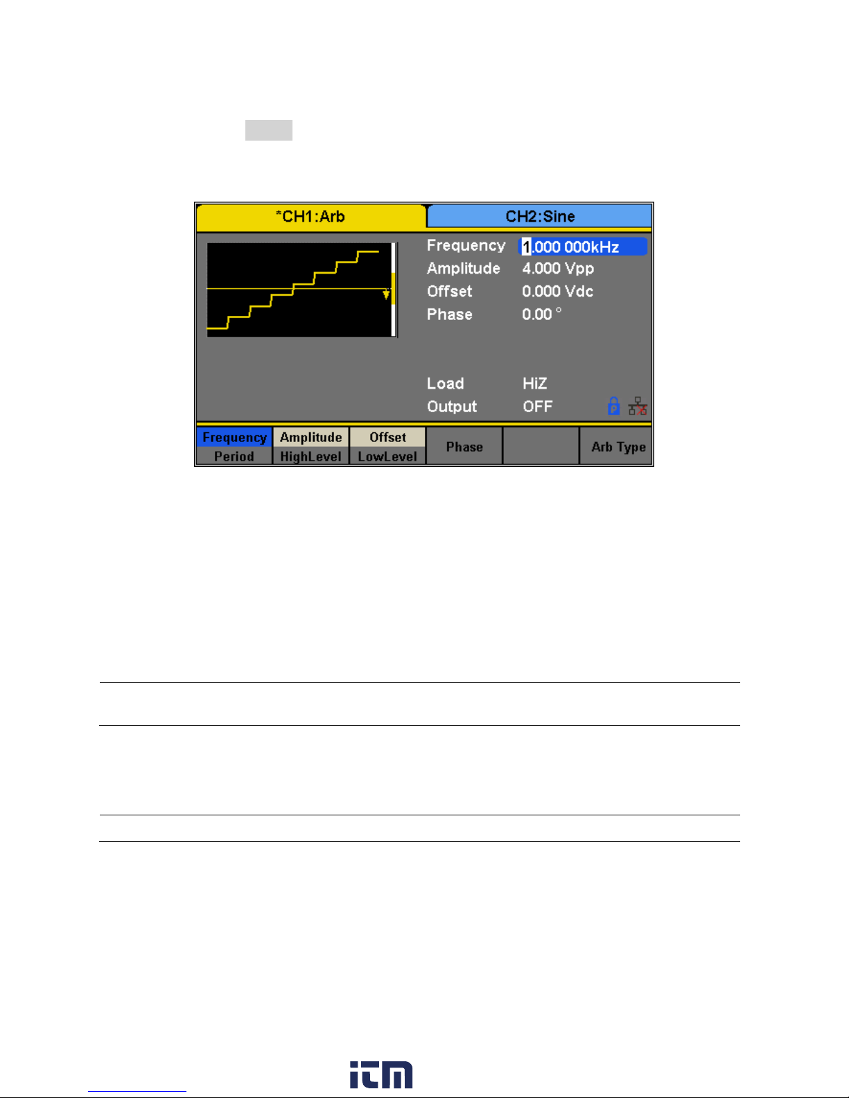
5. Once selected, press the knob to confirm and set the waveform or navigate to page 3/3
Figure 24 - Configuring an Arbitrary Waveform
Note: The 100MB non-volatile memory is shared between storing/recalling user-defined arbitrary
waveforms and instrument settings.
Note: EasyWave software supports Windows XP/Vista/7/8 (32 bit and 64 bit) only.
and press the Accept option from the menu.
6. The generator will return to the main Arb parameter menu and the waveform display
area will show the waveform shape of the selected predefined arbitrary waveform. For
example, the screenshot below shows the display of the predefined StairUp signal.
7. Adjust frequency, amplitude, and other parameters as desired.
Generate User-Defined Waveforms
The generator has approximately 100MB of non-volatile memory that can store more than
1,000 user-defined arbitrary waveforms. Each stored waveforms have 16K pts (16384 pts)
exactly.
EasyWave software will allow users to easily create a custom arbitrary waveform and load it
into the internal memory.
To load a wave created from EasyWave to the internal memory of the unit or saved to a USB
flash drive, follow the steps below:
36
www. .com
information@itm.com1.800.561.8187
Page 51

1. Setup Press the Waveforms button.
Figure 25 - User-Defined Arbitrary Waveform
Figure 26- Load an Arb Waveform from External
USB
2. Go to the second page of waveform options by pressing the 1/2 . softkey. .
Select and press the Arb softkey from the menu.
3. Press Arb Type and select Stored Waveforms to see a list of all arbitrary waveform files
created and loaded from EasyWave software.
4. Rotate the knob to choose the desired waveform. Then select Recall or press the knob
to recall the corresponding waveform.
5. If the wave is located in a USB flash drive, the user will have to select the external
memory drive from the menu above, as shown in the following picture:
37
www. .com
information@itm.com1.800.561.8187
Page 52

6. Use the knob to navigate to the file and either press the Recall softkey or press the knob
to load the waveform.
If the waveform is sent to the unit using EasyWave, the file will be saved to the internal
memory. If it is loaded to a USB flash drive, then the waveform can be recalled from the
USB flash drive.
Configure Harmonic Generator
Configure the built-in harmonic generator to output harmonics with a specified order,
amplitude and phase. This feature follows the Fourier series, as explained below.
According to the Fourier series, a periodic time domain waveform is the superposition of a
series of sine waveforms as shown in the equation below:
Generally, the component with f1 is called the fundamental frequency. A1 is the fundamental
waveform's amplitude and φ1 is the fundamental waveform phase. The frequencies of the
other components (called harmonics) are all integer multiples of the fundamental frequency.
Components whose frequencies are odd multiples of the fundamental waveform frequency are
called odd harmonics and components whose frequencies are even multiples of the
fundamental waveform frequency are called even harmonics.
To select and configure the Harmonics Generator, follow the steps below:
1. Press Waveforms button.
2. Press Sine softkey.
3. Press the Harmonic softkey to toggle the function on or off.
4. If the “On” option is pressed, then the Harmonic Parameter softkey will be available.
5. Press Harmonic Parameter to enter the following screen.
38
www. .com
information@itm.com1.800.561.8187
Page 53

Item Menu
Function
Type
Set the harmonic type to “odd”, “ever” or “all”.
Order
Set the order of the harmonic.
Harmonic
Ampl
Set the amplitude of the harmonic.
Harmonic
Phase
Set the phase of the harmonic.
Return
Return to the sine parameters menu.
Figure 27 - Harmonic Generator
Table 6 - Harmonics Generator Menu
To Select the Harmonic Type
The 4050B can output odd harmonics, ever harmonics and user-defined orders of harmonics.
1. Press TYPE TO SELECT THE DESIRED HARMONIC TYPE.
2. Press Even, and the instrument will output fundamental waveform and even harmonics.
3. Press Odd, and the instrument will output fundamental waveform and odd harmonics.
4. Press All, and the instrument will output the fundamental waveform and all the user-defined
orders of harmonics.
To Set the Harmonic Order
www. .com
39
information@itm.com1.800.561.8187
Page 54

1. Press Order.
Modulation Type
Parameter Settings
The range is limited by the maximum output frequency of the instrument and
current fundamental waveform frequency.
Range: 2 to maximum output frequency of the instrument ÷ current fundamental
waveform frequency
The maximum is 10.
2. Use the numeric keyboard or knob to input the desired value.
When the knob is used, the changes to the “Harm Order” will be immediate.
When the numeric keypad is used, after entering the value, the Accept softkey
should be pressed to enter the value.
To Select the Harmonic Amplitude
1. Press Order to select the sequence number of the harmonic to be set.Press Harmonic Ampl
to set the amplitude of the harmonic selected. The units available are Vpp, mVpp and dBc.
2. This process should be repeated for each harmonic.
To Select the Harmonic Phase
After entering the harmonic setting menu, press Harmonic Phase to set the phase of each
harmonic.
1. Press Order to select the sequence number of the harmonic to be set.
2. Press Harmonic Phase to set the phase of the harmonic selected. Use the arrow keys and
knob to change the value. Alternatively, use the numeric keyboard to input the phase value
and then select the unit ° (degrees).
This process should be repeated for each harmonic.
3.4 Configure Modulation Output
Use the Mod key to generate modulated waveforms. The generator can generate AM, FM, ASK,
FSK, PSK, PM, PWM and DSB-AM modulated waveforms. Modulating parameters vary with the
types of the modulation.
40
www. .com
information@itm.com1.800.561.8187
Page 55

AM
source (internal/external), depth, modulating frequency, modulating
waveform and carrier.
DSB-AM
source (internal/external), modulating frequency, modulating waveform
and carrier
FM
source (internal/external), modulating frequency, frequency deviation,
modulating waveform and carrier
PM
source (internal/external), phase deviation, modulating frequency,
modulating waveform and carrier
ASK
source (internal/external), key frequency and carrier
FSK
source (internal/external), key frequency, hop frequency and carrier
PSK
source (internal/external), key frequency, polarity and carrier
PWM
source (internal/external), modulating frequency, width/duty cycle
deviation, modulating waveform and carrier
Table 7 - Modulation Type
Note: Noise and DC waveforms cannot be modulated.
AM Modulation
The modulated waveform consists of two parts: the carrier and the modulating waveform. In
AM, the amplitude of the carrier varies proportionally with the instantaneous voltage of the
modulating waveform.
Press Mod → Type → AM, the parameters of AM modulation are shown in Figure 28.
41
www. .com
information@itm.com1.800.561.8187
Page 56

Function
Menu
Settings
Description
Type
AM
Amplitude modulation
Source
Internal
The source is internal
External
The source is external. Use the [Aux In/Out]
connector at the rear panel.
AM Depth
Set the modulation depth.
Shape
Sine
Choose the modulating waveform.
Square
Triangle
UpRamp
DnRamp
Noise
Arb
AM Freq
Set the modulating waveform frequency.
Frequency range: 1 mHz to 20 kHz (internal source
only).
Figure 28 - Setting Interface of AM Modulation
Table 8 - AM Modulation Menu Description
www. .com
42
information@itm.com1.800.561.8187
Page 57

Selecting Modulation Source
Do not connect more than ± 6 V into the Modulation In terminal. This
will damage the instrument and void its warranty.
Note: Noise can be used as modulating waveform but cannot be used as the carrier.
The generator can accept a modulating signal from an internal or external modulation source.
Press Mod → AM → Source to select “Internal” or “External” modulation source. The default is
“Internal”.
Internal Source
When internal AM modulation source is selected, press Shape to select Sine, Square, Triangle,
UpRamp, DnRamp, Noise or Arb as the modulating waveform.
Square: 50% duty cycle
Triangle: 50% symmetry
UpRamp: 100% symmetry
DnRamp: 0% symmetry
Arb: the arbitrary waveform selected for the current channel
External Source
When external AM modulation source is selected, the generator accepts an external
modulating signal from the [Aux In/Out] connector at the rear panel. At this time, the
amplitude of the modulated waveform is controlled by the voltage applied to the connector.
For example, if the modulation depth is set to 100%, the output amplitude will be the maximum
when the modulating signal is +6V and the minimum when the modulating signal is -6V.
Key Points:
The generator can use one channel as a modulating source for the other channel. The following
example takes the output signal of CH2 as the modulating waveform.
1. Connect the CH2 output terminal to [Aux In/Out] connector on the rear panel using a BNC
43
www. .com
information@itm.com1.800.561.8187
Page 58

cable.
2. Select CH1 and press Mod to select the desired modulation type as well as set the
corresponding parameters, and then select external modulation source.
3. Select CH2 and select the desired modulating waveform and set the corresponding
parameters.
4. Press Output to enable the output of CH1.
To Set Modulation Depth
Modulation depth expressed as a percentage indicates the amplitude variation degree. AM
modulation depth varies from 1% to 120%. Press AM Depth to set the parameter.
For an external source, the depth of AM is controlled by the voltage level on the
connector connected to the [Aux In/Out]. ± 6 V correspond to 100% depth.
When external modulation source is selected, this menu is hidden.
To Set Modulation Frequency
When an internal modulation source is selected, press AM Freq to highlight the parameter, and
then use the numeric keyboard or knob to input the desired value.
The modulation frequency ranges from 1 mHz to 20 kHz.
When an external modulation source is selected, this menu is hidden.
DSB-AM Modulation
DSB-AM is an abbreviation for Double-Sideband Suppressed Carrier – Amplitude Modulation.
Press Mod → Type → DSB-AM. The parameters of DSB-AM modulation are shown in Figure 29.
44
www. .com
information@itm.com1.800.561.8187
Page 59
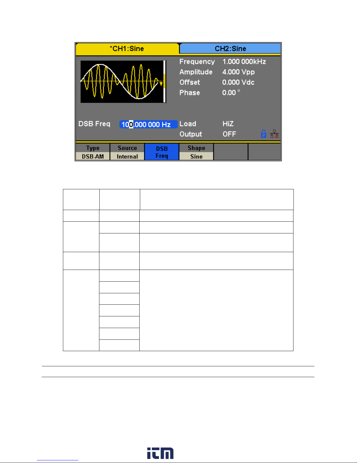
Function
Menu
Settings
Description
Type
DSB-AM
DSB Amplitude modulation.
Source
Internal
The source is internal.
External
The source is external. Use the [Aux In/Out]
connector at the rear panel.
DSB Freq
Set the modulating waveform frequency.
Frequency range: 1 mHz to 20 kHz (internal source)
Shape
Sine
Choose the modulating waveform.
Square
Triangle
UpRamp
DnRamp
Noise
Arb
Figure 29 - Setting Interface of DSB-AM Modulation
Table 9 - DSB-AM Modulation Menu Description
Note: The methods of setting the parameters of DSB-AM are similar to AM.
45
www. .com
information@itm.com1.800.561.8187
Page 60

FM Modulation
Function
Menu
Settings
Description
Type
FM
Frequency modulation
Source
Internal
The source is internal
External
The source is external. Use the [Aux In/Out]
connector at the rear panel.
Freq Dev
Set the frequency deviation
Shape
Sine
Choose the modulating waveform.
Square
Triangle
UpRamp
DnRamp
Noise
Arb
Figure 30 - Setting Interface of FM Modulation
The modulated waveform consists of two parts: the carrier and the modulating waveform. In
FM, the frequency of the carrier varies with the instantaneous voltage of the modulating
waveform.
Press Mod → Type → FM; the parameters of FM modulation are shown in Figure 30.
46
www. .com
information@itm.com1.800.561.8187
Page 61

FM Freq
Set the modulating waveform frequency.
Frequency range: 1 mHz to 20 kHz (internal source).
Function
Menu
Settings
Description
Type
PM
Phase modulation
Table 10 - FM Modulation Menu Description
Note: The methods of setting the parameters of FM are similar to AM.
Figure 31 - Setting Interface of PM Modulation
To Set Frequency Deviation
Press FM Dev to highlight the parameter and use the numeric keyboard or arrow keys and knob
to input the desired value.
The deviation should be equal to or less than the carrier frequency.
The sum of the deviation and the carrier frequency should be equal to or less than
maximum frequency of the selected carrier waveform.
PM (Phase Modulation)
The modulated waveform consists of two parts: the carrier and the modulating waveform. In
PM, the phase of the carrier varies with the instantaneous voltage level of the modulating
waveform.
Press Mod → Type → PM; the parameters of PM modulation are shown in Figure 31.
www. .com
47
information@itm.com1.800.561.8187
Page 62

Source
Internal
The source is internal
External
The source is external. Use the [Aux In/Out]
connector at the rear panel.
Phase Dev
Phase deviation ranges from 0° to 360°.
Shape
Sine
Choose the modulating waveform.
Square
Triangle
UpRamp
DnRamp
Noise
Arb
PM Freq
Set the modulating waveform frequency.
Table 11 - PM Modulation Menu Description
Note: The methods of setting the parameters of FM are similar to AM.
To Set Phase Deviation
Press Phase Dev to highlight the parameter and use the numeric keyboard or arrow keys and
knob to input the desired value.
The range of phase deviation is from 0° to 360° and the default value is 100°.
FSK Modulation
The FSK is Frequency Shift Keying, the output frequency switches between two preset frequencies
(carrier frequency and the hop frequency or sometimes known as mark frequency (1) and space
frequency (0)).
Press Mod → Type → FSK; the parameters of FSK modulation are shown in Figure 32.
www. .com
48
information@itm.com1.800.561.8187
Page 63

Function
Menu
Settings
Description
Type
FSK
Frequency shift keying modulation
Source
Internal
The source is internal
External
The source is external. Use the [Aux In/Out]
connector at the rear panel.
Key Freq
Set the frequency at which the output frequency
shifts between the carrier frequency and the hop
frequency (internal modulation only): 1 mHz to 50
kHz.
Hop Freq
Set the hop frequency.
Figure 32 - Setting Interface of FSK Modulation
Table 12 - FSK Modulation Menu Dscription
To Set Key Frequency
When internal modulation source is selected, press Key Freq to set the rate at which the output
frequency shifts between “carrier frequency” and “hop frequency”.
Use the numeric keyboard or knob to input the desired value.
The key frequency ranges from 1 mHz to 50 kHz.
When external modulation source is selected, this menu is hidden.
www. .com
49
information@itm.com1.800.561.8187
Page 64

To Set Hop Frequency
Function
Menu
Settings
Description
Note: The methods of setting the parameters of FSK are similar to AM.
Figure 33 - Setting Interface of ASK Modulation
The range of the hop frequency depends on the carrier frequency currently selected. Press Hop
Freq to highlight the parameter and use the numeric keyboard or knob to input the desired
value.
Sine: 1 uHz to max output depending on model.
Square: 1 uHz to max output depending on model.
Ramp: 1 uHz to 500 kHz
Arb: 1 uHz to 6 MHz
ASK Modulation
When using ASK (Amplitude Shift Keying), the carrier frequency and key frequency will need to
be set. The key frequency is the shift rate of the modulated waveform amplitude.
Press Mod → Type → ASK; the parameters of ASK modulation are shown in Figure 33.
www. .com
50
information@itm.com1.800.561.8187
Page 65

Type
ASK
Amplitude shift keying modulation
Source
Internal
The source is internal
External
The source is external. Use the [Aux In/Out]
connector at the rear panel.
Key Freq
Set the frequency at which the output amplitude
shifts between the carrier amplitude and zero
(internal modulation only): 1 mHz to 50 kHz.
Function
Menu
Settings
Description
Type
PSK
Phase shift keying modulation
Table 13 - Table 13 - ASK Modulation Menu
Description
Note: The methods of setting the parameters of ASK are similar to AM.
Figure 34 - Setting Interface of PSK Modulation
PSK Modulation
When using PSK (Phase Shift Keying), configure the generator to “shift” its output phase
between two preset phase values (carrier phase and modulating phase). The default
modulating phase is 180°.
Press Mod → Type → PSK; the parameters of PSK modulation are shown in Figure 34.
www. .com
51
information@itm.com1.800.561.8187
Page 66
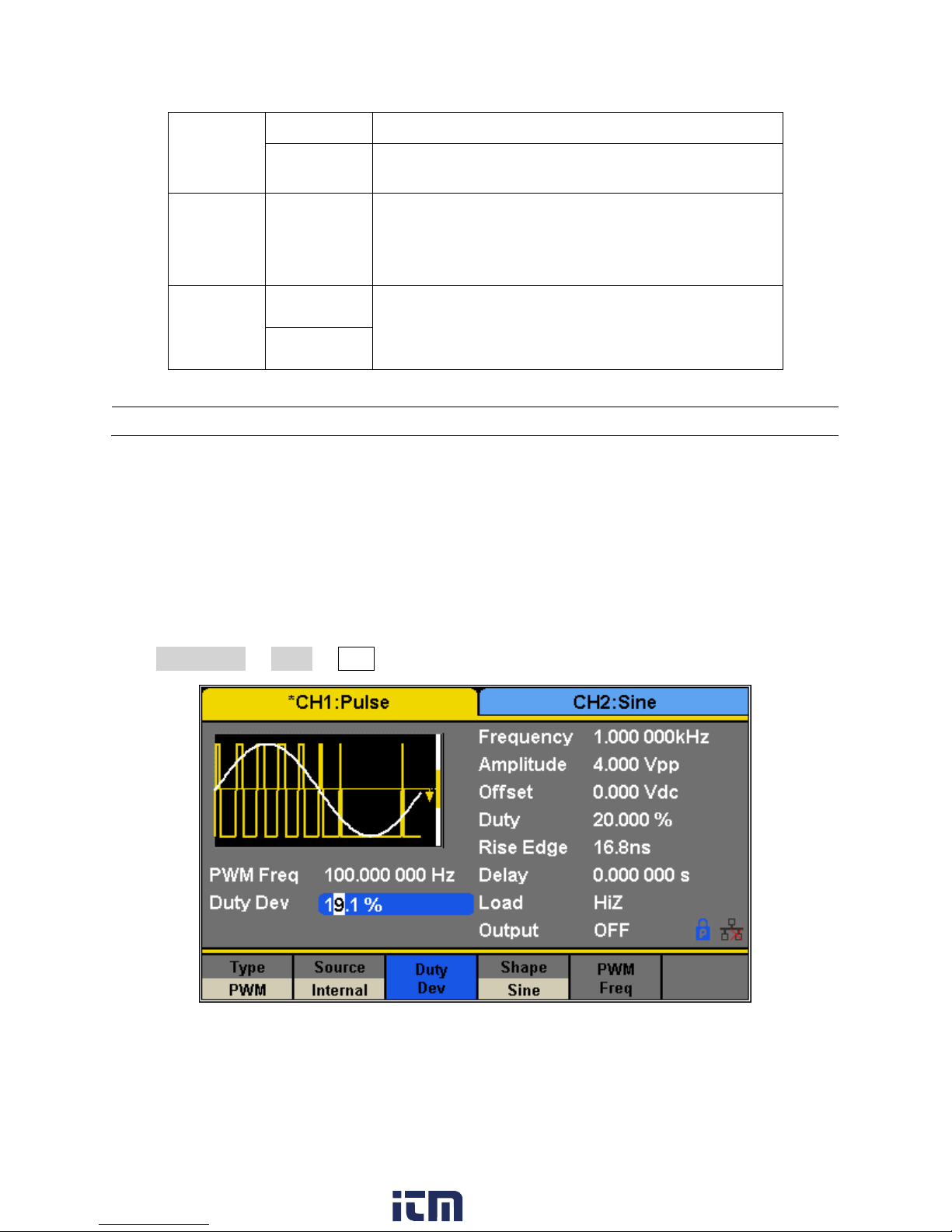
Source
Internal
The source is internal
External
The source is external. Use the [Aux In/Out]
connector at the rear panel.
Key Freq
Set the frequency at which the output phase shifts
between the carrier phase and 180° (internal
modulation only): 1 mHz to 20 kHz.
Polarity
Positive
Set the modulating polarity
Negative
Table 14 - PSK Modulation Menu Description
Note: The methods of setting the parameters of PSK are similar to AM.
Figure 35 - Setting Interface of PWM Modulation
PWM (Pulse Width Modulation)
In PWM (Pulse Width Modulation), the pulse width of the pulse varies with the instantaneous
voltage of the modulating waveform. The carrier can only be a pulse waveform.
Press Waveforms → Pulse → Mod the parameters of PWM modulation are shown in Figure 35.
www. .com
52
information@itm.com1.800.561.8187
Page 67
Function
Menu
Settings
Description
Type
PWM
Pulse width modulation. The carrier is pulse.
Source
Internal
The source is internal
External
The source is external. Use the [Aux In/Out]
connector at the rear panel.
Width
Dev
Set the width deviation.
Duty Dev
Set the duty deviation.
Shape
Sine
Choose the modulating waveform.
Square
Triangle
UpRamp
DnRamp
Noise
Arb
PWM
Freq
Set the modulating waveform frequency.
Frequency range: 1 mHz to 20 kHz (Internal source
only).
Table 15 - PWM Modulation Menu Description
To Set Pulse Width/Duty Deviation
Width Deviation represents the variation of the modulated waveform pulse width relative to
the original pulse width. Press Width Dev to highlight the parameter, and use the numeric
keyboard or knob to input the desired value as shown in the Figure 36.
www. .com
53
information@itm.com1.800.561.8187
Page 68

Figure 36 - Width Deviation Setting Interface
Figure 37 - Duty Deviation Setting Interface
The width deviation cannot exceed the current pulse width.
The width deviation is limited by the minimum pulse width and current edge time setting.
Duty Deviation represents the variation (%) of the modulated waveform duty cycle relative to
the original duty cycle. Press Duty Dev to highlight the parameter and use the numeric
keyboard or knob to input the desired value as shown in the Figure 37.
The duty deviation cannot exceed the current pulse duty cycle.
The duty deviation is limited by the minimum duty cycle and current edge time setting.
54
www. .com
information@itm.com1.800.561.8187
Page 69

Duty deviation and width deviation are dependent. Once one parameter is changed, the
Function
Menu
Description
Sweep time
Set the time span of the sweep in which the
frequency changes from the start frequency to stop.
Start Freq/
Mid Freq
Set the start frequency of the sweep/
Set the center frequency of the sweep.
Stop Freq
Freq Span
Set the stop frequency of the sweep;
Set the frequency span of the sweep.
Source
Internal
Choose internal source as a trigger.
External
Choose external source as a trigger. Use
the [Aux In/Out] connector at the rear
Note: The methods of setting the parameters of PWM are similar to AM.
Figure 38 - Sweep Configuration
other will be automatically changed.
3.5 Configure Sweep Output
In the sweep mode, the generator steps from the start frequency to the stop frequency in the
sweep time specified by the user. The waveforms that support sweep include sine, square, ramp
and arbitrary.
www. .com
55
information@itm.com1.800.561.8187
Page 70

Manual
Trigger a sweep manually.
Trig Out
Off
Disable trigger out.
On
Enable trigger out.
Type
Linear
Set the sweep with linear profile.
Log
Set the sweep with logarithmic profile.
Direction
Up
Sweep upward.
Down
Sweep downward.
Table 16 - Sweep Function
To select and configure the Sweep Function, follow the steps below:
1. Press the Sweep button.
Sweep time
2. Enter the Sweep Time using the keypad or knob.
Sweep Frequency
3. Press Start Freq and Stop Freq softkeys or Center Freq and Freq Span softkeys to set the
range of the frequency sweep.
a. Start Frequency and Stop Frequency
Start Frequency and Stop Frequency are the lower and upper limits of the frequency
for sweep. The Start Frequency must be less than or equal to the Stop Frequency.
b. Center Frequency and Frequency Span
Center Frequency = (|Start Frequency + Stop Frequency|)/2
Frequency Span = Stop Frequency – Start Frequency
4. Press the key again to switch between the two sweep range modes.
Sweep Trigger Source
5. Press the Source softkey.
6. A new window will open and three options are shown: The sweep trigger source can be
internal, external or manual. The generator will generate a sweep output when a trigger
signal is received.
Internal Trigger
56
www. .com
information@itm.com1.800.561.8187
Page 71

a. Press the Source softkey.
Figure 39 - Trigger Types
b. Press the Internal softkey to select an internal trigger.
The generator outputs a continuous sweep waveform when internal trigger is
selected. The default is “Internal”.
External Trigger
a. Press the Source softkey.
b. Press the External softkey to select an external trigger.
The generator uses the trigger signal input to the [Aux In/Out] connector at the rear
panel. A sweep will be generated once a TTL pulse with specified polarity is sent. To
set the CMOS pulse polarity refer to the Direction section at the end of this section.
Manual Trigger
a. Press the Source softkey.
b. Press the Manual softkey.
A sweep will be generated when the Trigger softkey is pressed.
7. After selecting the type of trigger and pressing the softkey to select it, the user will exit
the Trigger Source menu.
Trig out
8. In the menu of the Sweep function, press Trig Out.
9. Toggle the softkey On and the [Aux In/Out] connector at the rear panel will output the
trigger signal.
57
www. .com
information@itm.com1.800.561.8187
Page 72

Sweep Type
Figure 40 - Linear Sweep Interface
10. In the Sweep Function menu, press the Page 1/2 . softkey to access the second page of
Sweep Options. “Linear” and “Log” sweep types are supported. The default type is
“Linear”.
A. LINEAR SWEEP
In linear sweep, the output frequency of the instrument varies linearly with the sweep
time.
o Press the Linear softkey. A straight line is displayed on the waveform indicating that
the output frequency will vary linearly.
B. LOG SWEEP
In log sweep, the output frequency of the instrument varies proportionally to the
logarithm of the sweep time.
o Press the Log softkey.
An exponential curve is displayed on the waveform indicating that the output
frequency changes logarithmically.
58
www. .com
information@itm.com1.800.561.8187
Page 73

Figure 41 - Log Sweep Interface
Note: Sweep function is only available for sine, square, ramp, and arbitrary waveforms. It is not available for
pulse, noise, or DC waveforms.
Note: Sweep function cannot operate when in burst mode.
Note: Gated burst operation is for use with an internal or external source only.
Direction
1. In the Sweep Function menu, press the Page 1/2 . softkey to access the second page of
Sweep Options.
2. Press the Direction softkey to toggle between the two options: Up and Down.
Up: the generator will sweep from the Start frequency to the Stop frequency.
Down: the generator will sweep from the Stop frequency to the Start frequency.
3.6 Configure Burst
The Burst function allows a specified number of periods of a waveform to be output (N-Cycle
mode) or the waveform can be gated by an external signal (Gated mode). Any waveform except
DC may be used as the carrier, with the limitation on the noise waveform in which only gated
burst function is supported.
59
www. .com
information@itm.com1.800.561.8187
Page 74
Burst Type
Burst Type
Trigger Source
Waveforms
N-Cycle
Internal/External/Manual
Sine, Square, Ramp, Pulse, Arbitrary.
Infinite
External/Manual
Sine, Square, Ramp, Pulse, Arbitrary.
Gated
Internal/External
Sine, Square, Ramp, Pulse, Noise,
Item
Description
NCycle
Use the N-Cycle mode.
Cycles
Set the number of the bursts in N-Cycle.
Infinite
Set the number of the bursts in N-Cycle
to be infinite.
Start Phase
Set the start phase of the burst.
Source
Internal
Choose internal source as a
trigger. (Not available for
Infinite Burst).
External
Choose external source as a
trigger. Use the [Aux In/Out]
connector at the rear panel.
Manual
Trigger a burst with manual
trigger.
Delay
Set the delay time before the burst
Off
Disable trigger out.
Table 17 - Burst Type: Trigger Source and
Waveforms
Table 18 - NCycle Burst Menu
The 4050B provides three burst types: N-Cycle, Infinite and Gated. The default is N-Cycle.
Burst Type, Trigger Source and Waveform
N-Cycle
Waveforms that support N-Cycle burst include sine, square, ramp, pulse and arbitrary. Set the
number of waveform cycles in an N-Cycle burst (1 to 50,000 or Infinite).
If Infinite is chosen, then a continuous waveform will be generated once a trigger occurs.
60
www. .com
information@itm.com1.800.561.8187
Page 75
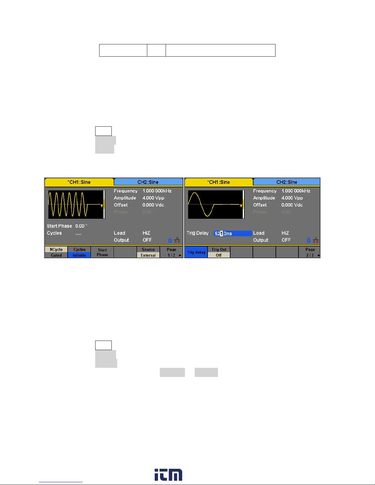
Trig Out
On
Enable trigger out.
Figure 42 – Burst NCycle
Cycles
In N-Cycle mode, the generator will output a specified number N of waveform cycles (periods)
after receiving the trigger signal.
To configure Burst Cycles, follow these instructions:
1. Press the Burst button.
2. Press the NCycle softkey.
3. Press the Cycles softkey.
4. Use the numeric keyboard or knob to input the desired number of cycles.
Infinite
In infinite mode, the cycle number of the waveform is set as an infinite value. The generator
outputs a continuous waveform after receiving the trigger signal. Waveforms that support
infinite mode include sine, square, ramp, pulse and arbitrary.
To configure Burst Infinite Cycles, follow the steps below:
1. Press the Burst button.
2. Press the NCycle softkey.
3. Press the Infinite softkey.
4. Set the trigger source to either External or Manual (Internal trigger source is not
available when Burst NCycle is set to Infinite).
61
www. .com
information@itm.com1.800.561.8187
Page 76

Item
Description
Polarity
Positive
Set the polarity for the gated signal.
Negative
Start Phase
Set the start phase of the burst.
Burst Period
Set the burst Period.
Source
Internal
Choose internal source as a trigger.
External
Choose external source as a trigger. Use
the [Aux In/Out] connector at the rear
panel.
Figure 43 – NCycle Burst Manual Trigger
Table 19 - Gated Burst
This trigger softkey becomes available when
the manual trigger is selected.
Gated
In gated mode, the generator controls the waveform output according to the gated signal level.
When the gated signal is ON, the generator outputs a continuous waveform. When the gated
signal is OFF, the generator first completes the output of the current period and then stops.
Waveforms that support gated burst include sine, square, ramp, pulse, noise and arbitrary.
62
www. .com
information@itm.com1.800.561.8187
Page 77
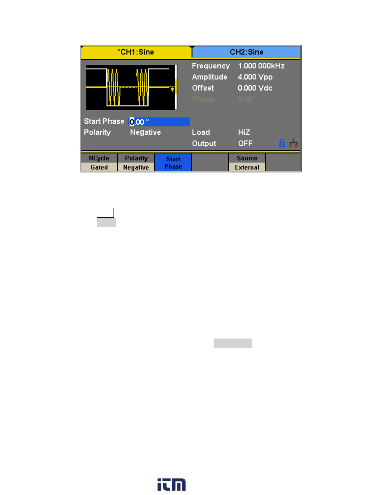
Figure 44 - Negative Gated Burst
To configure Burst Gated, follow the steps below:
1. Press the Burst button.
2. Press the Gated softkey.
3. Select a Polarity for the gate. This determines whether the gate will go from low to high
(positive gate) or from high to low (negative gate).
Common Settings for NCycle and Gated Burst:
Start Phase
Define the start point in a waveform. The phase varies from 0° to 360° and the default is 0°. For
an Arbitrary Waveform, 0° is the first waveform point.
Burst Period
Burst Period is only available when the trigger source is internal. It is defined as the time from
the start of a burst to the start of the next one. Choose Burst Period and use the numeric
keyboard or knob to input the desired value.
Burst Period ≥ 0.99 μs + carrier period × burst number
If the current burst period set is too short, the generator will increase this value
automatically to allow outputting the specified number of cycles.
Trig Delay
Set the time delay between the trigger input and the start of the N-Cycle burst.
63
www. .com
information@itm.com1.800.561.8187
Page 78

Burst Trigger Source
The burst trigger source can be internal, external or manual. The generator will generate a
burst output when a trigger signal is received and wait for the next trigger source.
To configure the Trigger Source, once in the Burst menu:
Internal Trigger
1. Press the Source softkey.
2. Press the Internal softkey.
3. The generator outputs a continuous burst waveform when internal trigger is selected.
4. Go to the second page of this menu, press Trig Out and select “Up” or “Down” and the
[Aux In/Out] connector at the rear panel will output a trigger signal with specified edge
or set it “Off” to not output a signal from the [Aux In/Out].
External Trigger
1. Press the Source softkey.
2. Pres the External softkey.
3. The generator accepts the trigger signal input from the [Aux In/Out] connector at the
rear panel when external trigger is selected. A burst will be generated on a CMOS pulse
with specified polarity. To set the CMOS pulse polarity go to the second page of this
menu, and press Edge and select “Up” or “Down”.
Manual Trigger
1. Press the Source softkey.
2. Pres the External softkey.
3. Press the Trigger softkey to generate a burst.
64
www. .com
information@itm.com1.800.561.8187
Page 79
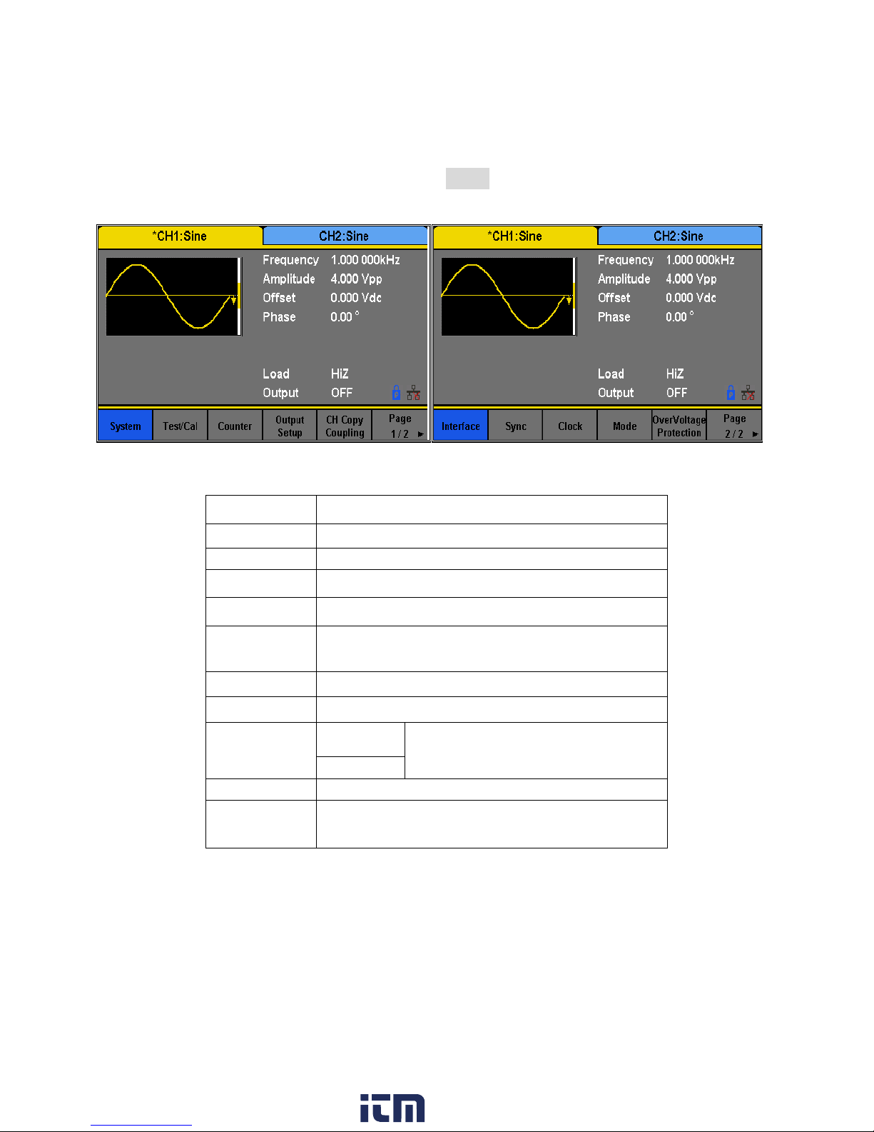
4 Utility Functions
Item
Description
System
Set the system configuration.
Test/Cal
Test and calibrate the instrument.
Counter
Frequency counter settings.
Output Setup
Set the output parameters of CH1 and CH2.
CH Copy
Coupling
Set the track, channel coupling or channel copy
function.
Interface
Set the parameters of remote interfaces.
Sync
Set the sync output.
CLKSource
Internal
Choose the system clock source.
External
Mode
Choose Phase-locked or independent mode.
OverVoltage
Protection
Turn on/off the overvoltage protection
function.
Figure 45 - Utility Menu
Table 20 - Utility Menu
The utility menu can be accessed by pressing the Utility button from the front panel. This
section describes all the configurable settings of this menu.
www. .com
65
information@itm.com1.800.561.8187
Page 80

4.1 System Settings
Item
Description
Number format
Set the numerical format.
Language
English
Set the language.
Chinese
PowerOn
Default
All the settings return to their defaults at power on.
Last
All the settings return to the settings at the last power
down.
Set to
Default
Set all the settings to their defaults.
Beeper
On
Turn on the key sound (beep).
Off
Turn off the key sound (beep).
ScrnSvr
(Screensaver)
1min
Enable screensaver for the specified amount.
5min
15min
30min
Figure 46 - System Options
1. Press the Utility button.
2. Pres the System softkey to enter the system options:
www. .com
66
information@itm.com1.800.561.8187
Page 81
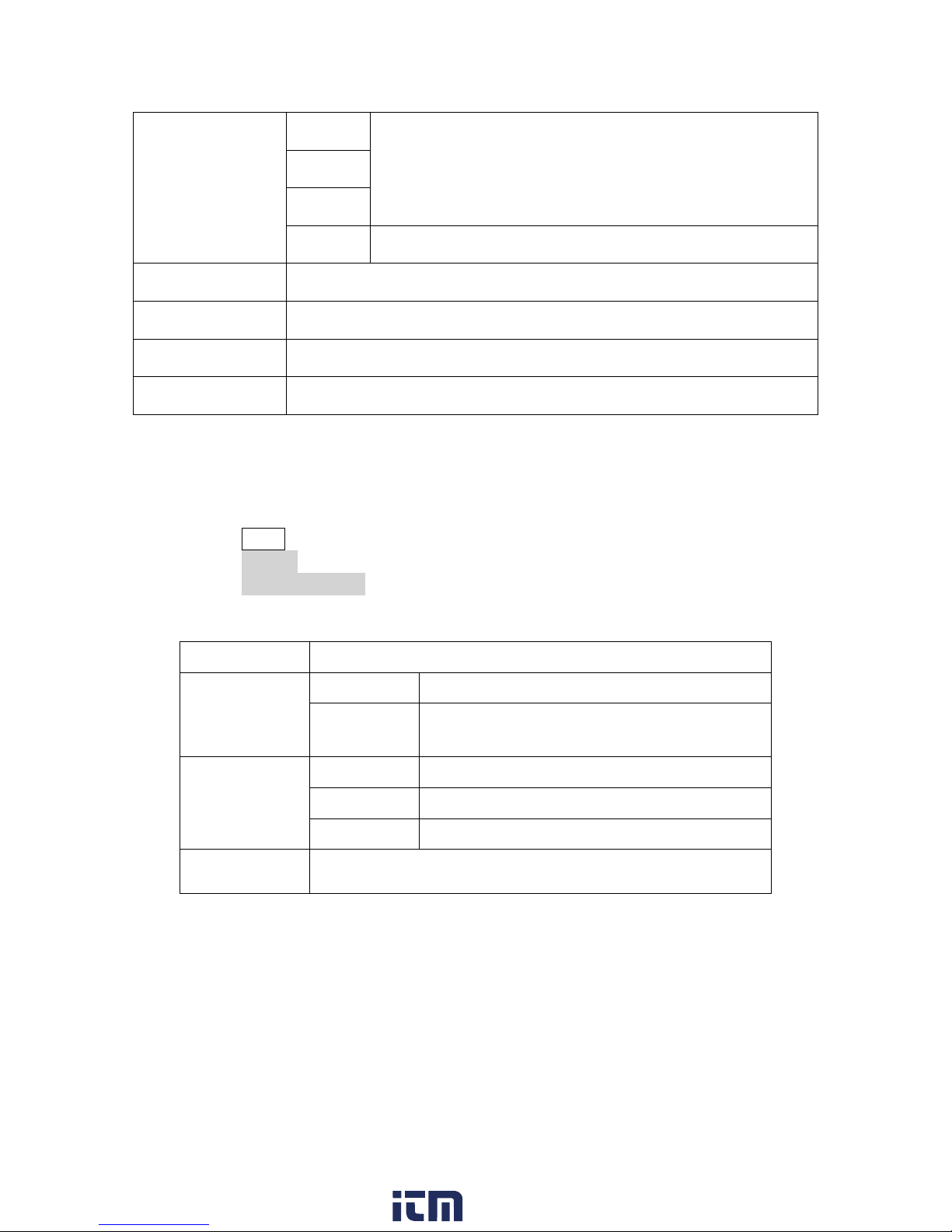
1hour
2hour
5hour
Off
Disables screensaver.
System Info
View system information
Firmware Update
Update firmware using a USB flash drive.
Help
View the help information.
Accept
Save the current settings and return to the Utility menu.
Item
Description
Point
.
Use a dot to represent the decimal point;
,
Use a comma to represent the decimal
point.
Separator
On
Enable the Separator.
Off
Disable the Separator.
Space
Use Space as the separator.
Accept
Save the current settings and return to the System menu.
Figure 47 - System Settings
Table 21 - Numerical Format
Numerical Format
To change the numerical format of the generator, follow these instructions:
a. Press the Utility button.
b. Press the System softkey.
c. Press the Number Format softkey.
The options for the Numerical Format are shown in Table 21 - Numerical Format
www. .com
67
information@itm.com1.800.561.8187
Page 82

Figure 48 - Numerical Format Options
Language Setup
The generator offers two languages (English and Simplified Chinese).
a. Press the Utility button.
b. Press the System softkey.
c. Press the Language softkey to select the desired language.
Power On
The 4050B series offers two options for power on settings: Last and Default. To set either option,
follow these instructions:
a. Press the Utility button
b. Press the System softkey.
c. Press the PowerOn softkey to toggle between the two options:
Default: Denotes the factory defaults except certain parameters (such as Language).
Last: Includes all system parameters and states set when the unit was last powered
down, except channel output state. This setting is stored in non-volatile memory and
will not be affected by the Set To Default operation.
68
www. .com
information@itm.com1.800.561.8187
Page 83

Set to Default
Setting
Default value
Output
Function
Sine Wave
Frequency
1 kHz
Amplitude/Offset
4 Vpp/0 Vdc
Phase
0°
Load
High Z
Modulation
Carrier
1 kHz Sine Wave
Modulating
100 Hz Sine Wave
AM Depth
100%
FM Deviation
100 Hz
ASK Key Frequency
100 Hz
FSK Key Frequency
100 Hz
FSK Hop Frequency
1 MHz
PSK Key Frequency
10 0Hz
PM Phase Deviation
100°
PWM Width Dev
190 μs
Sweep
Start/Stop Frequency
500 Hz/1.5 kHz
Sweep Time
1 s
Trig Out
Off
Mode
Linear
Table 22 - Factory Default Settings
Sets the unit to defaults settings:
a. Press the Utility button.
b. Press the System softkey.
c. Press the Set to Default to set the system to the default setting. The default settings
of the system are:
69
www. .com
information@itm.com1.800.561.8187
Page 84

Direction
↑
Burst
Burst Period
10 ms
Start Phase
0°
Cycles
1 Cycle
Trig Out
Off
Delay
521 ns
Trigger
Source
Internal
Key Sound (Beeper)
Turns the instrument key press sound ON or OFF. When off, this setting will also disable the
sound for any errors that may occur during front panel or remote operation.
a. Press the Utility button.
b. Press the System softkey.
c. Press the Beeper softkey to select “On” or “Off”. The default is “On”.
Screen Saver
This setting allows to enable or disable the screen saver.
a. Press the Utility button.
b. Press the System softkey.
c. Press the Page 1/2 to access the second page of options.
d. Press the ScrnSvr softkey to select “On” or “Off”.
System Info
a. Press the Utility button.
b. Press the System softkey.
c. Press the Page 1/2 to access the second page of options.
d. Press the System Info option to see the following screen.
70
www. .com
information@itm.com1.800.561.8187
Page 85

Do not turn off the power while the generator's firmware is being updated.
Figure 49 - System Information Screen
Note: A configuration file (*.CFG) may or may not be included with a given firmware update. If a CFG file is
not included with a firmware update then it will not be required for that specific update.
Firmware Update
The software version and configuration file of the generator can be updated directly via USB
flash drive. To update the firmware, follow the steps below:
a. Insert USB flash drive with firmware update file (*.ADS) and configuration file (*.CFG)
to USB host interface on the front panel of the generator.
b. Press the Utility button.
c. Press the System softkey.
d. Press the Page 1/2 to access the second page of options.
e. Press the Firmware Update softkey. Or press Store/Recall directly.
f. Select the firmware file (*.ADS) and choose Recall to update the system software.
g. After the updating is finished, the generator will restart automatically.
h. Press Utility → Page 1/2 → Firmware Update. Or press Store/Recall directly.
i. Select the configuration file (*.CFG) and choose Recall to update the configuration file.
j. After the update completes, the generator will restart automatically.
71
www. .com
information@itm.com1.800.561.8187
Page 86

Menu
Description
UP
Cursor upward to select.
Down
Cursor downward to select.
Select
Read the currently selected help information.
Cancel
Exit the built-in help system.
Figure 50 - Built-in Help Menu
Figure 51 - Built-in Help
Built-in Help
The 4050B Series provides a built-in help system. There are 10 topics in the help list. Use the
softkeys to navigate through the options and select a topic to read. To access the Built-in Help
follow the below instructions:
a. Press the Utility button.
b. Press the System softkey.
c. Press the Page 1/2 to access the second page of options.
d. Press the Help softkey to enter the following screen:
www. .com
72
information@itm.com1.800.561.8187
Page 87

4.2 Test/Cal
Item
Description
ScrTest
Run the screen test program.
KeyTest
Run the keyboard test program.
LEDTest
Run the key indicator lights test program.
BoardTest
Run the hardware circuit self-test program.
Cancel
Return to the Test/Cal menu.
Table 23 - Self Test Menu
Figure 52 - Screen Test
This function allows the user to run self-diagnostics.
a. Press the Utility button.
b. Press the Test/Cal softkey. The following options will be available:
c. To enter any test, press the corresponding sotkey:
ScrTest
a. Press ScrTest to enter the screen test interface.
b. The prompt message, “Please press ‘7’ key to continue. press ‘8’ key to exit.” is
displayed.
c. Press the ‘7’ key to test the display for color deviation, bad pixels or display errors.
73
www. .com
information@itm.com1.800.561.8187
Page 88

Key Test
Figure 53 - Key Test
a. Press the KeyTest softkey to enter the key test interface.
The on-screen white rectangle shapes represent the front panel keys. The circle
between two arrows represents the knob.
b. Test all keys by pressing them and knob by rotating it. Also verify that all the backlight
keys illuminate correctly.
The items tested will change to blue.
LED Test
a. Press the LEDTest sotkey to enter the LED test interface.
The on-screen white rectangle shapes represent the front panel keys. The prompt
message, “Please press ‘7’ Key to continue, press ‘8’ Key to exit.” is displayed.
b. Press the ‘7’ key continuously for testing the key backlights.
The items tested will change to blue.
74
www. .com
information@itm.com1.800.561.8187
Page 89

Figure 54 - LED Test
Figure 55 - Board Test
Board Test
a. Press the BoardTest softkey to test the internal hardware of the generator. It will
indicate either “pass” or “fail”.
4.3 Frequency Counter
The generator has a built-in frequency counter that can measure frequencies between 100 mHz
to 200 MHz (DC Coupling) and 10 Hz to 200 MHz (AC Coupling). This unit has a dedicated
connector in the back panel for the frequency counter.
To configure the Frequency Counter follow the steps below:
a. Press the Utility button.
75
www. .com
information@itm.com1.800.561.8187
Page 90
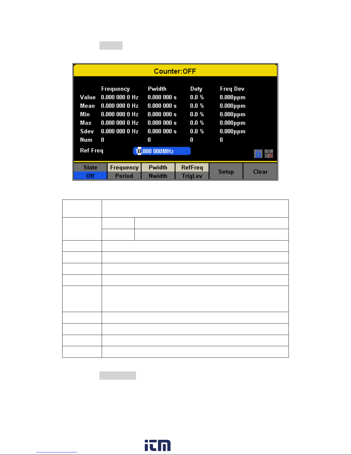
b. Press the Counter softkey. The following options will be available:
Function
Menu
Description
State
Off
Turn the counter on.
On
Turn the counter off.
Frequency
Measure frequency.
Period
Measure period.
PWidth
Measure positive width.
NWidth
Measure negative width.
RefFreq
Set the reference frequency. The instrument will display the
deviation in parts per million (ppm) between the measured
frequency and the reference frequency.
TrigLev
Set the trigger level voltage.
Duty
Measured duty cycle.
Setup
Set the counter configuration.
Clear
Clear the statistical data.
Figure 56 - Frequency Counter
Table 24 - Frequency Counter Function Description
c. Press the State On/Off to enabled the counter.
d. Select the parameter to be measured and press its respective softkey. The
frequency counter can measure the below parameters:
Frequency
www. .com
76
information@itm.com1.800.561.8187
Page 91

Period
Positive pulse width (Pwidth)
Negative pulse width (Nwidth)
e. Press the RefFreq/TrigLevel to set the reference frequency or to set a trigger level:
Reference Frequency:
The counter will display the deviation in parts per million between the measured
frequency and the reference frequency.
Trigger Level:
Sets the trigger level of the measurement system. The counter triggers and
displays the measurement readings when the input signal reaches the specified
trigger level. The default is 0 V and the available range is from -3 V to 1.5 V.
Choose TrigLev and use the numeric keyboard to input the desired value and
select the unit (V or mV) from the pop-up menu. Alternatively, use the knob and
arrow keys to change the parameter value.
f. Press the Setup softkey to configure the coupling mode, high frequency rejection or
set the configuration back to default.
Coupling Mode
Sets the coupling mode of the input signal to “AC” or “DC”. The default is “AC”.
HFR
High Frequency Rejection can be used to filter out high-frequency components
of a measured signal and improve the measurement accuracy in low-frequency
signal measurement. Press HFR to enable or disable this function. The default is
“Off”.
o Enable High Frequency Rejection when 250 kHz or less signals are measured
to filter out unwanted high-frequency interference.
o Disable High Frequency Rejection when a signal with a frequency higher than
250 KHz is measured. The maximum frequency that can be counted is 200
MHz.
4.4 Output
The 4050B series has output settings that can be configured to either adjust the display to
match the output of the unit to high impedance or 50 Ω, change the polarity of the output, and
set the output phase to be the same for both channels
a. Press the Ch1/Ch2 button to toggle between channel 1 and channel 2 to configure
respective output parameters of each channel.
b. Press the Utility button.
c. Press the Output Setup softkey. The Output options will be displayed on the next
screen:
77
www. .com
information@itm.com1.800.561.8187
Page 92

Figure 57 - Output Setup
Note: Press the output key for two seconds to toggle between High Impedance and 50 Ω.
Load
For [CH1] and [CH2] connectors on the front panel, the generator has an output impedance of
50 Ω. If the load does not match the load impedance, the displayed voltage will not be the same
as the output voltage setting on the generator. The Load function is used to match the
displayed voltage with the expected one by scaling the display of the generator since this
setting does not actually change the output impedance.
Steps for setting the load:
1. Press the Utility button.
2. Press the Output Setup softkey.
3. Press the Load softkey to change the output load display.
High Impedance: HiZ.
50 Ω (default).
Polarity
1. Press the Utility button.
2. Press the Output Setup softkey.
3. Press the Polarity softkey to set the output signal as normal or inverted. The waveform’s
inversion is relative to the offset voltage, as shown in the following figure.
78
www. .com
information@itm.com1.800.561.8187
Page 93

Note: The Sync signal related to the waveform is not inverted when the waveform is inverted.
EqPhase
The unit can set both channel 1 and channel 2 to be in phase. Once the selected channel has
the required phase follow the steps below to copy the phase to the other channel:
1. Press the Utility button.
2. Press the Output Setup.
3. Press the EqPhase softkey to align the phases of CH1 and CH2.
Combining Waveforms (Wave Combine)
The CH1 output port of the generator outputs the waveform of CH1 in the normal mode, while
the waveform of CH1+CH2 (the sum of the two waveforms) can be output in the combined
mode. Similarly, the CH2 output port of the generator outputs the waveform of CH2 in the
normal mode while the waveform of CH1+CH2 can be output in the combined mode.
1. Press the Utility button.
2. Press the Output Setup softkey.
3. Press the Wave Combine softkey to enter the waveforms combining interface, as shown
in the following figure.
79
www. .com
information@itm.com1.800.561.8187
Page 94
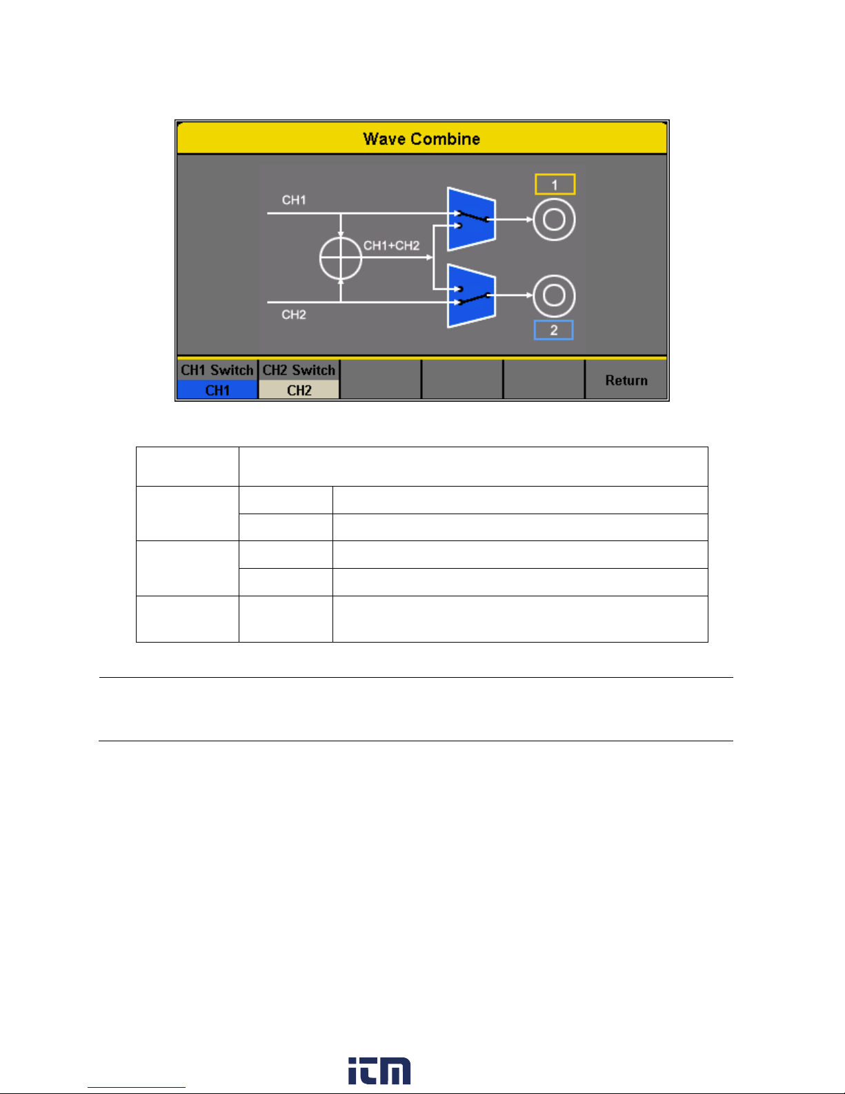
Function
Menu
Description
CH1 Switch
CH1
Output the CH1 waveform.
CH1+CH2
Output the CH1+CH2 waveform.
CH2 Switch
CH2
Output the CH2 waveform.
CH1+CH2
Output the CH1+CH2 waveform.
Return
Save the current settings and exit the current
interface.
Figure 58 - Wave Combine Menu
Notes:
1. Combining with a Square waveform is not possible.
2. When the waveform combining function is enabled, the output impedance of the two channels
will be set to be the same as the currently operated channel.
4.5 CH Copy/Coupling
Channel Copy
The generator supports a state and waveform copy function between its two channels. This
copies all parameters and states (including the channel output state) and arbitrary waveform
data from one channel to the other channel.
80
www. .com
information@itm.com1.800.561.8187
Page 95
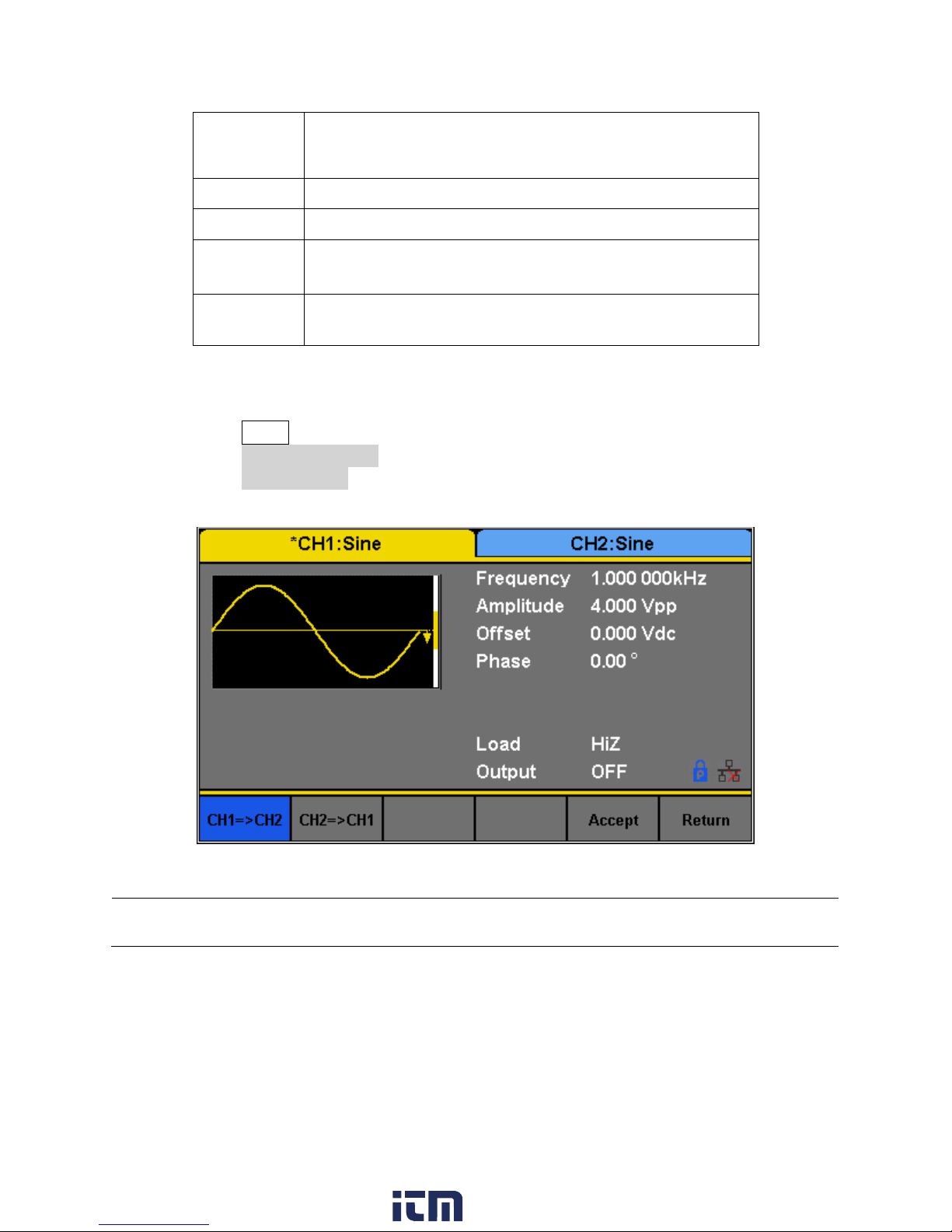
Function
Menu
Description
CH1=>CH2
Copy all parameters and states of CH1 to CH2.
CH2=>CH1
Copy all parameters and states of CH2 to CH1.
Accept
Perform the current selection and return to the Utility
menu.
Cancel
Give up the current selection and return to the Utility
menu.
Table 25 - Channel Copy Options
Figure 59 - Channel Copy
Note: The channel coupling or track function and the channel copy function are mutually exclusive. When
channel coupling or track function is enabled, the menu Channel Copy is hidden.
To configure channel copy options, follow the steps below:
1. Press the Utility button.
2. Press the CH Copy Coupling softkey.
3. Press the Channel Copy softkey to enter the following interface.
Channel Coupling
The generator supports frequency, amplitude and phase coupling. Users can set the frequency
deviation/ratio, amplitude deviation/ratio or phase deviation/ratio of the two channels. When
coupling is enabled, CH1 and CH2 can be modified simultaneously. When the frequency,
amplitude or phase of one channel (as the reference) is changed, the corresponding parameter
81
www. .com
information@itm.com1.800.561.8187
Page 96

of the other channel will be changed automatically and always keeps the specified frequency
Figure 60 - Channel Coupling
deviation/ratio, amplitude deviation/ratio or phase deviation/ratio relative to the modified
channel.
To configure channel coupling settings, follow the instructions below:
1. Press the Utility button.
2. Press the CH Copy Coupling softkey.
3. Press the Channel Coupling, to enter the following menu:
Frequency Coupling
To configure the Frequency Coupling function, follow the steps below:
1. Press the FreqCoup softkey to turn frequency coupling “On” or “Off”. The default is
“Off”.
2. Press the FreqMode softkey to choose “Deviation” or “Ratio” and use the numeric
keyboard or knob to input the desired value.
Deviation: the frequency deviation between CH1 and CH2. The resulting signal is
represented by: FreqCH2 - FreqCH1 = FreqDev.
Ratio: the frequency ratio of CH1 and CH2. The resulting signal is represented by:
FreqCH2/FreqCH1 = FreqRatio.
Amplitude Coupling
To configure the Amplitude Coupling function, follow the steps below:
1. Press AmplCoup to turn amplitude coupling “On” or “Off”. The default is “Off”.
82
www. .com
information@itm.com1.800.561.8187
Page 97

2. Press AmplMode to choose “Deviation” or “Ratio” and use the numeric keyboard or
Notes: 1. Channel coupling is only available when the waveforms of the two channels are basic waveforms:
Sine, Square, Ramp and Arbitrary.
2. When the Phase Coupling function is enabled, if the phase of one channel is changed, the phase of the
other channel will be changed accordingly. At this point, aligning phase between the two channels can
be achieved without using the Eqphase operation.
3. Channel coupling and channel function are mutually exclusive. When channel coupling is enabled, the
menu Channel Copy is hidden.
knob to input the desired value.
Deviation: the amplitude deviation between CH1 and CH2. The resulting signal is
represented by: AmplCH2-AmplCH1 = AmplDev.
Ratio: the amplitude ratio of CH1 and CH2. The resulting signal is represented by:
AmplCH2/AmplCH1 = AmplRatio.
Phase Coupling
To configure the Phase Coupling function, follow the steps below:
1. Press PhaseCoup to turn phase coupling “On” or “Off”. The default is “Off”.
2. Press PhaseMode to choose “Deviation” or “Ratio”, and then use the numeric keyboard
or knob and arrow keys to input the desired value.
Deviation: the phase deviation between CH1 and CH2. The resulting signal is
represented by: PhaseCH2 - PhaseCH1 = PhaseDev.
Ratio: the phase ratio of CH1 and CH2. The resulting signal is represented by:
PhaseCH2/PhaseCH1 = PhaseRatio.
Tracking
When the Tracking function is enabled, by changing the parameters or states of CH1, the
corresponding parameters or states of CH2 will be adjusted to the same values or states
automatically. At this point, the dual channels can output the same signal.
To configure the Tracking (Track) Function, follow the steps below:
1. Pres the Utility button.
2. Press the CH Copy Coupling softkey.
3. Press the Track softkey to enable or disable the track function.
When the track function is enabled, channel copy and coupling functions are disabled.
The channel selection is switched to CH1 and cannot be switched to CH2, as shown in
the following figure.
83
www. .com
information@itm.com1.800.561.8187
Page 98

Figure 61 - Tracking
Figure 62 - Phase Deviation
4. Press PhaseDev to enter the following menu:
5. Then use the numeric keyboard or knob and arrow keys to input the desired value for
the phase deviation between CH1 and CH2. The resulting signal is represented by:
PhaseCH2-PhaseCH1=PhaseDev.
84
www. .com
information@itm.com1.800.561.8187
Page 99

4.6 Remote Interface
Function
Menu
Description
GPIB
Set the GPIB address.
LAN State
On
Turn on LAN.
Off
Turn off LAN.
LAN Setup
Set the IP address, subnet mask and gateway.
Accept
Save the current settings and return to the Utility menu.
Figure 63 - Remote Interface
Table 26 - Remote Interface Menu
The 4050B Series can be controlled remotely via USB, LAN and GPIB (optional) interfaces.
1. Press the Utility button.
2. Press the Page 1/2 softkey.
3. Press the Interface softkey to set the LAN parameters or GPIB address in the following
screen:
The unit will recognize if USBTMC or GPIB interface is being used and output to that interface.
GPIB takes precedence as it locks the unit to GPIB mode when the adapter is connected to USB
host in the front panel. LAN state is by default on. To use USBTMC or GPIB, set the LAN state to
off.
www. .com
85
information@itm.com1.800.561.8187
Page 100

USB Interface
Note: A type A to type B USB cable is required for PC connectivity.
Note: Users who have LabVIEW™ or NI-VISA installed will automatically have this driver in their system.
In this case, driver download is not required.
Note: The AK40G is an adapter and not a GPIB controller. The computer must have a GPIB bus controller to
connect to the adapter.
Note: Be sure all devices are powered off before connecting the adapter to the USB port of the generator
and/or the GPIB port on your computer.
The instrument has a USB interface (USBTMC) in the rear panel for remote communication with
EasyWave software.
To connect with EasyWave software, you must install NI-VISA. NI-VISA is downloadable from
LabVIEW™ website. There are no settings for USBTMC. Make sure to set the LAN State to OFF.
GPIB Interface
The generator can be remotely controlled via GPIB using the optional AK40G USB-to-GPIB
adapter.
Connecting AK40G
1. Connect the USB end of the AK40G to the front USB host port of the instrument. Since
this port is a shared port, an external USB flash drive cannot be used during GPIB
operation.
2. Connect the GPIB end of the AK40G to the computer’s GPIB bus controller via a GPIB
cable.
3. On the AK40G adapter, a RED LED light indicates power to the adapter. A YELLOW LED
light indicates communication is in process.
86
www. .com
information@itm.com1.800.561.8187
 Loading...