

Page 1
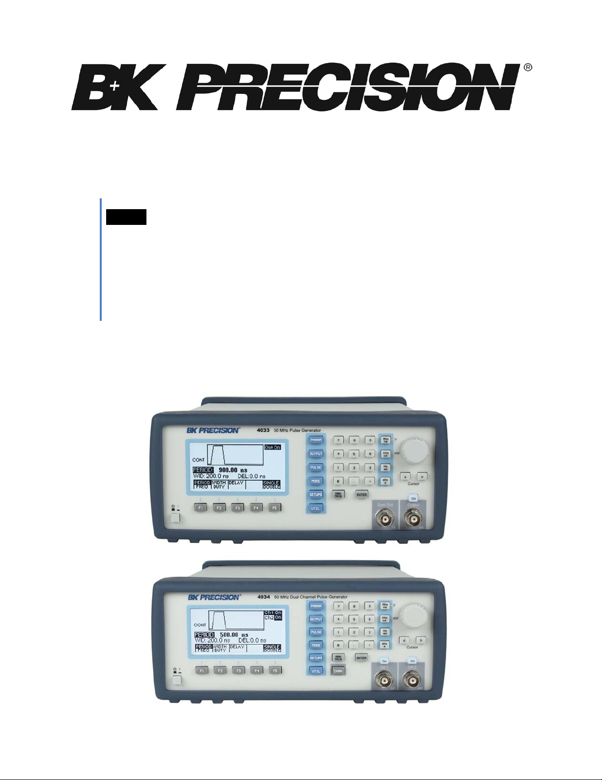
Model: 4033, 4034
50 MHz Programmable Pulse
USER MANUAL
Generator
Page 2

Do not alter the ground connection. Without the protective ground connection, all
accessible conductive parts (including control knobs) can render an electric shock.
To avoid electrical shock hazard, disconnect power cord before removing covers.
Safety Summary
The following safety precautions apply to both operating and maintenance personnel and must be
observed during all phases of operation, service, and repair of this instrument. Before applying power,
follow the installation instructio ns and become familiar with the op e rating instructions for this
instrument.
Failure to comply with these precautions or with specific warnings elsewhere in this manual violates
safety standards of de s ign, manufacture, and intended use of the instrument. B&K PRECISI ON
assumes no liability for a customer ’s failure to comply with these requirements.
GROUND THE INSTRUMENT
To minimize shock hazard, the instrument chassis and cabinet must be connected to an electrical
ground. Thi s instrument is grounded through the ground conductor of the suppli ed, three-conductor ac
power cable. The power cable must be plugged into an approved three-conductor electrical outlet. Do
not alter the ground connection. Without the protective ground connection, all accessible conductive
parts (including control knobs) can render an electric shock. The power jack and mating plug of the
power cable meet IEC safety standards.
DO NOT OPERATE IN AN EXPLOSIVE ATMOSPHERE
Do not operate the instrument in the presence of flammable gases or fumes. Operation of any electrical
instrument in such an environmen t c onstitutes a definite safety hazard.
KEEP AWAY FROM LIVE CIRCUITS
Instrument covers must not be removed by operating personnel. Component replacement and internal
adjustments must be made by qualified maintenance personnel. Disconnect the power cord before
removing the instrument co ve r s and replacing components. Under certain conditions, even with the
power cable removed, dangerous voltages may exist. To avoid injuries, always disconnect power and
discharge ci rcuits before touching them.
DO NOT SERVICE OR ADJUST ALONE
Do not attempt any internal service or adjustment unless another person, capable of rendering first aid
and resuscitation, is present.
DO NOT SUBSTITUTE PARTS OR MODIFY THE INSTRUMENT
Do not install substitute parts o r perform any unauthorized modifications to this instrument. Return the
instrument to B&K Precision for service and repair to ensure that safety features are maintained.
WARNINGS AND CAUTIONS
WARNING and CAUTION statements, such as the following examples, denote a hazard and appear
throughout this manual. Follow all instructions contained in these statements.
A WARNING statement calls atte ntion to an operating procedure, practice, or condition, which, if not
followed correctly, could result in injury or death to pe rsonnel.
A CAUTION statement calls attention to an operating procedure, p ractice, or condition, which, if not
followed correctly, could result in damage to or destruction of part or all of the product.
WARNING:
The power jack and mating plug of the power cable meet IEC safety standards.
WARNING:
Refer servicing to qualified personnel.
2
Page 3
Before connecting the line cord to the AC mains, check the rear panel AC line
line voltage other than the indicated voltage can
destroy the AC line fuses. For continued fire protection, replace fuses only with
static discharge
(ESD). To avoid damage, be sure to follow proper procedures for handling, storing
sensitive
This product is subject to Directive 2002/96/EC of the
Electrical Shock hazard.
CAUTION:
voltage indicator. Applying a
CAUTION:
those of the specified voltage and current ratings.
This product uses components which can be damaged by electroand transporting parts and subassemblies which contain ESD-
components.
Compliance Statements
Disposal of Old Electrical & Electronic Equipment (Applicable in the European
Union and other European countries with separate collection systems)
European
Parliament and the Council of the European Union on waste
electrical and electronic equipment (WEEE) , and in
jurisdictions
adopting that Directive, is marked as being put on the market
after August 13, 2005, and should not be disposed of as
unsorted
municipal waste. Please utilize your local WEEE collection
facilities in the disposition of this product and otherwise
observe all applicable requirements.
Safety Symbols
Connect to safety earth ground using the wire recommended in the user manual.
This symbol on an instrument indicates that the user should refer to the operating
instructions located in the manual.
3
Page 4

Table of Contents
Safety Summary .............................................................................................. 2
Section 1 .......................................................................................................... 6
Introduction ........................................................................................................................ 6
1.1 Introduction .............................................................................................................................................. 6
1.2 Description ............................................................................................................................................... 6
1.3 Safety Remarks ....................................................................................................................................... 6
1.4 Package Contents ................................................................................................................................... 6
Specifications ..................................................................................................................... 7
Section 2 .......................................................................................................... 9
Installation .......................................................................................................................... 9
2.1 Introduction .............................................................................................................................................. 9
2.2 Mechanical Inspection ............................................................................................................................. 9
2.3 Initial Inspection ....................................................................................................................................... 9
2.4 Instrument Mounting ................................................................................................................................ 9
2.5 Product Dimensions ................................................................................................................................ 9
2.6 Power Requirements ............................................................................................................................. 10
2.7 Grounding Requirements ...................................................................................................................... 10
2.8 Signal Connections ................................................................................................................................ 10
2.9 RS-232 Connection ............................................................................................................................... 13
2.10 RS-232 Configuration .......................................................................................................................... 14
2.11 GPIB Address ...................................................................................................................................... 14
2.12 GPIB Connections ............................................................................................................................... 14
Section 3 ........................................................................................................ 15
Operating Instructions .................................................................................................... 15
3.1 General Description ............................................................................................................................... 15
3.2 Display Window ..................................................................................................................................... 16
3.3 Front Panel Controls .............................................................................................................................. 17
3.4 Back Panel Controls .............................................................................................................................. 17
3.5 Output connectors ................................................................................................................................. 19
3.6 MENU Keys ........................................................................................................................................... 19
3.7 ON Key .................................................................................................................................................. 29
3.8 Cursor Movement Keys ......................................................................................................................... 29
3.9 Rotary Input Knob .................................................................................................................................. 29
3.10 Power-On Settings .............................................................................................................................. 30
3.11 Memory ................................................................................................................................................ 30
3.12 Displaying Errors ................................................................................................................................. 30
3.13 Pulse Definitions .................................................................................................................................. 31
3.14 Pulse Parameter Limitations ................................................................................................................ 32
3.15 Pulse Definitions .................................................................................................................................. 33
Section 4 ........................................................................................................ 35
Programming .................................................................................................................... 35
4.1 Overview ................................................................................................................................................ 35
4.2 Device State .......................................................................................................................................... 36
4.3 Interface Function Subsets .................................................................................................................... 37
4.4 Device Address...................................................................................................................................... 37
4.5 Message Exchange Protocol ................................................................................................................. 37
4
Page 5

4.6 Instrument Identification ........................................................................................................................ 38
4.7 Instrument Reset ................................................................................................................................... 38
4.8 Self Test ................................................................................................................................................. 39
4.9 Command Syntax .................................................................................................................................. 39
4.10 Status Reporting .................................................................................................................................. 41
4.11 IEEE 488.2 Common Commands and Queries ................................................................................... 45
4.12 Instrument Control Commands ............................................................................................................ 48
4.13 IEEE 488.1 Interface Messages .......................................................................................................... 64
4.14 SCPI Command Tree .......................................................................................................................... 65
4.15 ASCII and GPIB Code Chart ............................................................................................................... 67
4.16 RS-232 Programm ing .......................................................................................................................... 69
5
Page 6

Section 1
Introduction
1.1 Introduction
This manual contains information required to operate, program, check, and maintain the 50 MHz programmable pulse
generator.
1.2 Description
The Model 4033 and 4034 are a high performance programmable pulse generators. The instrument generates pul s e
with a repetition rate to 50 MHz, width from 10 ns, variable delay, varia ble transition times and amplitude . The pulses
can be output in continuous, trigge red, gated , or burst mode with a n internal or external trigger signal.
The model 4033 and 4034 can be remotely operated via RS232 or GPIB interface bus and is SCPI compatible.
1.3 Safety Remarks
The model 4033 and 4034 are SAFETY CLASS 1 instruments. Before operation, review the safety summary at the
beginning of the manual.
1.4 Package Contents
The following list of items and accessories come in the package:
1. 4033 or 4034 Pulse Generator
2. AC power cord
3. CD containing use r man ual
4. Test report and certificate of calibration
5. RS-232 Serial Cable
6
Page 7

Specifications
MODELS
4033
4034
CHANNELS
1
2
FREQUENCY
0.1 Hz to 50 MHz
TIMING CHARA CTERISTICS
PERIOD
Range (single pulse)
20 ns to 10 s (50 MHz to 0.1 Hz repetition rate)
Range (double
pulse)
40 ns to 10 s (25 MHz to 0.1 Hz repetition rate)
Resolution
Up to 6 digits, limited to 10 ps
Accuracy
0.01 %
Jitter
< 0.01 % of setting +20 ps on Period, Width and Delay
WIDTH
Range
10 ns to (Period – 10 ns)
Resolution
Up to 6 digits, limited to 100 ps
Accuracy
(0.5% of setting +500 ps)
Double Puls e
(0.5% of setting +3 ns) for the second pulse
DELAY
Range
0ns to (Period – Width – 10 ns)
Resolution
Up to 6 digits, limited to 100 ps
Accuracy
±(0.5% of setting +500 ps)
DUTY
Range
1 to 99%
Resolution
3 digits (0.1%)
Accuracy
Limited by width and pulse accuracy
OUTPUT CHARA C TERISTICS
AMPLITUDE
High Level
-9.90 V to +10 V into 50 ohms load (-19.80 V to +20 V into open circuit)
Low Level
Range
-10 V to +9.90 V into 50 ohms load (-20 V to +19.80 V into open circuit)
Amplitude R ange
0.1V to 10V p-p into 50 ohms load (20 Vp-p max into open circui t)
Resolution
3 digits limited to 10 mV
Accuracy
1% of setting ± 10 mV into 50 ohms
Aberrations
Output
Resistance
50 ohms
Offset Accuracy
1% ± 25 mV
OPERATING MODES
Continuous
Output continuous at programmed period rate
Output quiescent until triggered by an internal, external, GPIB or manual
trigger, then generates one cycle at programmed period rate
Same as triggered mode except pulses are output for the duration of the
gated signal. The last cycle started is completed
Same as triggered mode for programmed number of cycles from 2 to
External Width
Trigger duration and rate sets pulse width and repetition
Specifications listed in manual are applicable after a powered 30 minute warm-up into a 50 Ω load
NOTE
All timing characteristics are measured at 50% of amplitude with fastest edge
Specifications are verified according to the performance check procedures.
Specifications not verified in the manual are either explanatory notes or general performance characteristics only.
Specifications and informatio n is s ub ject to change without notice. Fo r the most current and correct data please
www.bkprecision.com
visit
±
CYCLE
±
±
Range
±
<5% + 20 mV into 50 ohms load, for pulse levels between ±5 V
±
Triggered
Gated
Burst
999,999 as set by the N-BURST function
7
 Loading...