

Page 1
Data Sheet
50 MHz Programmable Pulse Generators
Models 4033 & 4034
Description Features & Benefits
The 4033 and 4034 are high performance programmable pulse generators for testing digital
systems and circuits based on TTL, CMOS, or
ECL technologies. Both instruments generate
clean and accurate pulses at up to 6 digits resolution with a repetition rate up to 50 MHz, variable pulse widths from 10 ns to 10 s, and pulse
delays from 0 ns to 10 s. Output levels are
adjustable from -10 V to +10 V, with pulse
amplitudes settable from 0.1 Vpp to 10 Vpp into
a 50 ohm load. All parameters, modes, and
functions are programmable via the front panel
or remote control commands. Additionally, the
pulse generators provide selectable complementary pulse and double pulse generation in continuous, triggered, gated, and counted burst
modes.
■ Repetition rate of 0.1 Hz to 50 MHz
■ Flexible trigger modes: Continuous, Triggered
(internal, external, manual), Gated Burst and
External Width
■ Pulse width programmable from 10 ns to 10 s
■ Transition times (rise and fall times) variable
from 6 ns to 100 ms
■ Programmable delay and double pulse
■ Predefined amplitude levels for ECL, TTL, and
CMOS signals
■ Store up to 99 different test setups with auto
retention of last power down setup
■ 10 Vpp into 50 ohm output
■ Closed case calibration
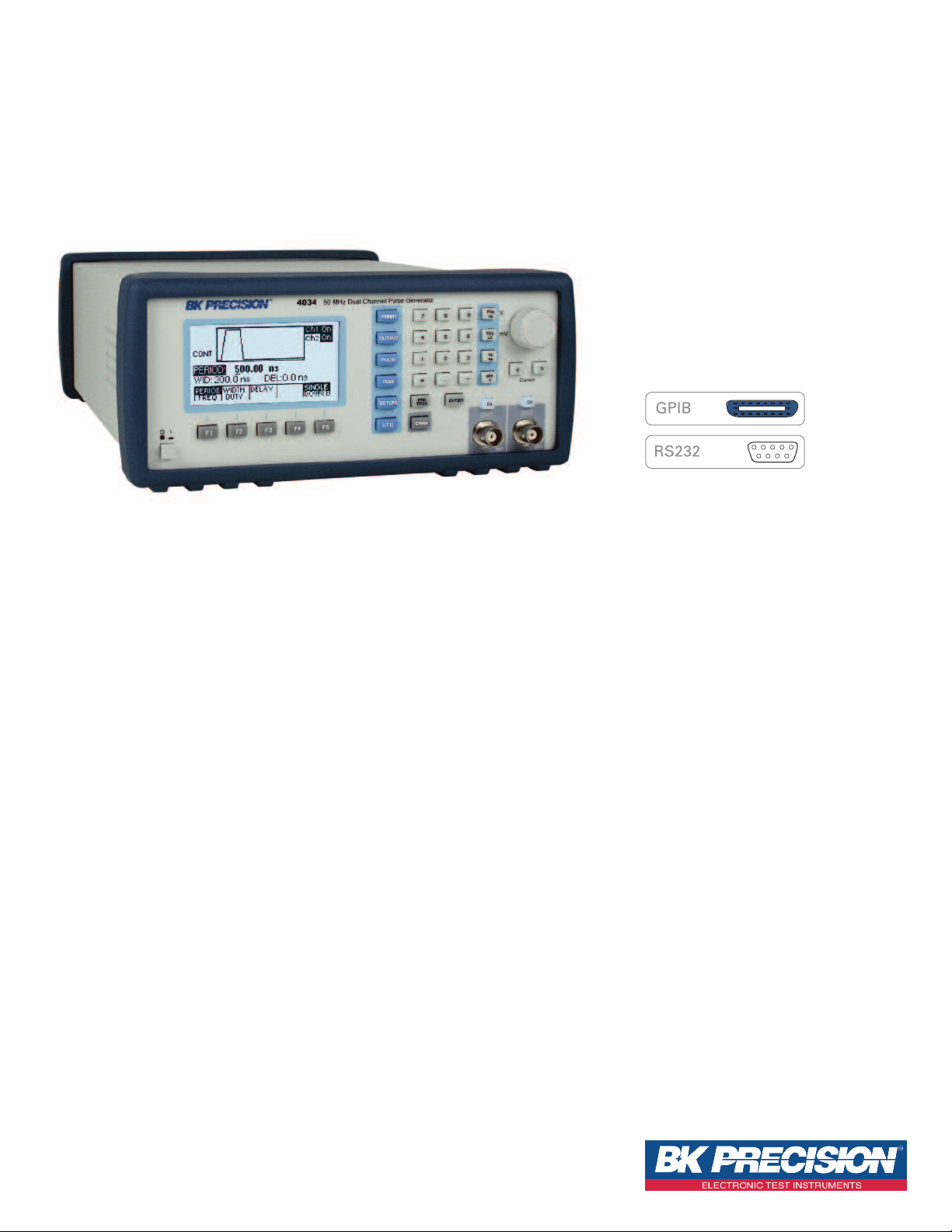
■ Programmable via GPIB and RS-232
■ SCPI compatible
■ Three year warranty
Dual-Channel Model 4034
■ Both channels offer full functionality and all
parameters such as pulse width and transition
time can be set independently
■ Synchronize both channels with the push of a
button
■ Saves cost and bench space
Applications
■ Automatic Test Equipment (ATE)
■ Avionics and radar testing
■ Switching power supply testing
■ Characterization of active components
Technical data subject to change
© B&K Precision Corp. 2010
wwwwww..bbkk pprreecc iissiioonn..ccoomm
Page 2
50 MHz Programmable Pulse Generators
odels 4033 & 4034
M
Industry Leading Performance
External Width
In the external width pulse mode, pulse period
and width are determined by an externally
applied signal. The pulse generator then applies
transition and level parameters to this signal in
order to generate the pulse. A power supply
designer for example could use this feature to
shape the width and period of the output signal
to drive the power supply’s FET transistors while
remaining synchronized with its control circuits.
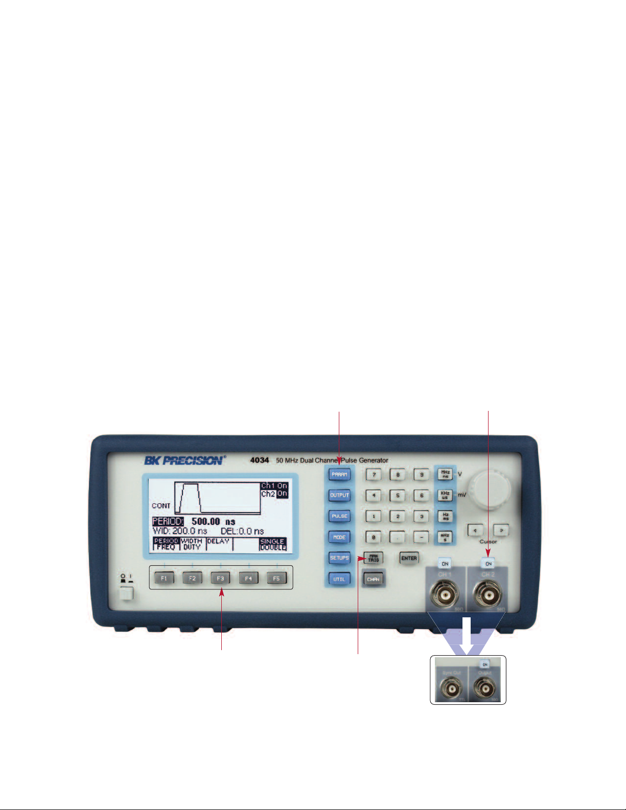
Front Panel Interface
Variable Transitions
For added flexibility, variable rise and fall times
can be programmed from 6 ns to 100 ms.
Various shapes of pulses can be obtained for
applications where parameters such as linearity,
switching times, or reflection times must be analyzed. Programmable rise and fall times could be
used to measure operational amplifier slew rates
and easily test thresholds of devices and circuits.
Menu Keys – Selects menu
options for waveform parameters
Straightforward User Interface
These generators use a menu-driven front panel
keypad and control knob to adjust all parameters.
The bright, easy-to-read display shows all relevant parameters along with a graphical representation of the output pulse. If an entered parameter is not compatible with the existing setup status, the operator is informed by an error message.
Users can conveniently select predefined amplitude levels for TTL, ECL, and CMOS signals, or
choose a custom amplitude level for specialized
applications.
Output On Button – Turns the
main output signal on or off
F1-F5 Key – Select menu options
that appear on the bottom section
of the LCD display
22 wwww ww ..bbkk pprr ee cc iissiioonn ..cc oomm
Manual Trigger Key – Sends
manual trigger pulse when
pushed (requires instrument
to be in manual trigger
mode)
4033 Output Section –
Main output and Sync
output
Page 3

50 MHz Programmable Pulse Generators
odels 4033 & 4034
M
Specifications
The specifications describe the instrument performance after 30 minutes warm-up period into a 50 Ω load. All timing characteristics are measured at 50% of
amplitude with fastest edges.
MM ooddeellss 4400 33 33 44003344
HANNELS
C
FREQUENCY 0.1 Hz to 50 MHz
TT IIMMIINNGG CC HH AARRAACC TT EE RRIISSTTIICC SS
Range (single pulse) 20 ns to 10 s (50 MHz to 0.1 Hz repetition rate)
Range (double
ulse)
ERIOD
P
WIDTH
DELAY
DUTY CYCLE
OOUUTTPPUUTT CC HH AARRAACC TT EE RR IISSTTIICC SS
AMPLITUDE
OOPPEE RRAA TT II NN GG MMOODD EESS
External Width Trigger duration and rate sets pulse width and repetition
PP UU LLSS EE FFUUNNCC TTIIOONN SS
p
Resolution Up to 6 digits, limited to 100 ps
ccuracy ±0.01 %
A
Jitter < 0.01 % of setting +20 ps on Period, Width and Delay
Range 10 ns to (Period – 10 ns)
esolution Up to 6 digits, limited to 100 ps
R
ccuracy ±(0.5% of setting +500 ps)
A
Double Pulse ±(0.5% of setting +3 ns) for the second pulse
ange 0 ns to (Period – Width – 10 ns)
R
Resolution Up to 6 digits, limited to 100 ps
Accuracy ±(0.5% of setting +500 ps)
Range 1 to 99%
Resolution 3 digits (0.1%)
Accuracy Limited by width and pulse accuracy
High Level Range
Low Level Range
Amplitude Range
Resolution 3 digits limited to 10 mV
Accuracy ±1% of setting ±10 mV into 50 Ω
Aberrations <5% + 20 mV into 50 Ω load, for pulse levels between ±5V
Output Resistance 50 Ω
Offset Accuracy ±1% ±25 mV
Continuous Output continuous at programmed period rate
Triggered
Gated
Burst
Single One pulse at each selected period up to 50 MHz repetition rate
Double
Output quiescent until triggered by an internal, external, GPIB
or manual trigger, then generates one cycle at programmed
Same as triggered mode except pulses are output for the dura-
tion of the gated signal. The last cycle started is completed
Same as triggered mode for programmed number of cycles from
One pair of pulses at each period up to 25 MHz repetition rate.
Both pulses have the same selected width; the position of
1 2
40 ns to 10 s (25 MHz to 0.1 Hz repetition rate)
-9.90 V to +10 V into 50 Ω load
(-19.80 V to +20 V into open circuit)
-10 V to +9.90 V into 50 Ω load
(-20 V to +19.80 V into open circuit)
0.1 V to 10 V p-p into 50 Ω load
(20 V p-p max into open circuit)
period rate
2 to 999,999 as set by the N-BURST function
the second pulse set by the delay control.
TT RRAA NN SS II TT IIOO NN TTIIMMEE SS
<6 ns to 100 ms variable. Leading and trailing edges settable
ange
R
Resolution 3 digits limited to 10 ps
Accuracy ±(5% of setting +2 ns)
Linearity
II NNTTEERRNNAA LL TTRR II GG GGEERR
ange 100 ns to 100 s
R
esolution 4 digits limited to 100 ns
R
Accuracy ±0.01%
II NNPP UUTT AA NN DD OO UU TTPPUU TT
Sensitivity 200 mVpp minimum
Minimum Width 10 ns
Maximum Rate 50 MHz
TRIGGER
INPUT
RREE MM OOTTEE PPRROO GG RRAA MM MMIINNGG
GGEE NNEE RR AALL
Electrical Discharge Immunity Conforms to EN55082
Operating Temperature 32 °F to 122 ° F (0 °C to 50 °C)
Input Impedance 10 kΩ
Input Protection ±15V DC plus peak AC
Range Selectable from -10 V to +10 V
Resolution 3 digits limited to 10 mV
Slope Selection Positive or Negative
SYNC OUTPUT
Interface GPIB and RS-232, IEEE-488.2 and SCPI compatible
GPIB Function Codes SH1, AH1, T6, L4, SR1, RL1, PP0, DC1,DT1, C0, E2
Memory
Power Requirements 100-240 V, ±10%, 48-66 Hz, 50 VA maximum
Dimensions WxHxD 8.4 x 11.8 x 3.5 inches (213 x 300 x 88 mm)
Net Weight 6.61 lbs (3 kg)
EMC
Safety Specifications Conforms to EN61010, CE Approved
Storage Temperature -4 ° F to 140 °F (-20 °C to 60 °C)
Humidity 90% RH at 32 °F to 86 °F (0 °C to 30 °C)
separately and limited to 20:1 ratio between settings into one of
the following ranges: 5 ns-100 ns; 50 ns-1.0 us; 500 ns-10 us;
.0 us-100 us; 50 us-1.0 ms; 500 us-10 ms, 5 ms – 100 ms
5
<5% deviation from a straight line between 10% and 90%
A TTL level pulse at the programmed period. Output impedance
is 50 Ω, protected against short circuit and up to ±15 V
accidental input. The high level is >2 V into 50 Ω and with 3.5
Non-volatile, stores up to 99 complete panel settings. Last user
Conforms to EN55011 class B for radiated and conducted
points, for transitions > 50 ns
ns typical transition times.
setup also retained at power down.
emissions
Three Year Warranty
Included accessories : AC Power cord, CD containing instruction manual, RS-232 cable,
test report and certificate of calibration
33 wwww ww ..bbkk pprr ee cc iissiioonn ..cc oomm
v092710_1
 Loading...