

Page 1
INSTRUCTION
MANUAL
MODEL 4011A
MANUAL DE
INSTRUCCIONES
MODELO 4011A
5 MHz FUNCTION
GENERATOR
with DIGITAL DISPLAY
5MHz GENERADOR DE FUNCIONES
CON DIGITOS INDICADOR
1
Page 2

TEST INSTRUMENT SAFETY
WARNING
Normal use of test equipment exposes you to a certain amount of danger from electrical shock because testing must sometimes be
performed where exposed voltage is present. An electrical shock causing 10 milliamps of current to pass through the heart will stop most
human heartbeats. Voltage as low as 35 volts dc or ac rms should be considered dangerous and hazardous since it can produce a lethal
current under certain conditions. Higher voltages pose an even greater threat because such voltage can more easily produce a lethal
current. Your normal work habits should include all accepted practices to prevent contact with exposed high voltage, and to steer current
away from your heart in case of accidental contact with a high voltage. You will significantly reduce the risk factor if you know and
observe the following safety precautions:
1. Don't expose high voltage needlessly. Remove housings and covers only when necessary. Turn off equipment while making test
connections in high-voltage circuits. Discharge high-voltage capacitors after removing power.
2. If possible, familiarize yourself with the equipment being tested and the location of its high voltage points. However, remember that
high voltage may appear at unexpected points in defective equipment.
3. Use an insulated floor material or a large, insulated floor mat to stand on, and an insulated work surface on which to place
equipment; and make certain such surfaces are not damp or wet.
4. Use the time proven "one hand in the pocket" technique while handling an instrument probe. Be particularly careful to avoid
contacting a nearby metal object that could provide a good ground return path.
5. When testing ac powered equipment, remember that ac line voltage is usually present on some power input circuits such as the on-
off switch, fuses, power transformer, etc. any time the equipment is connected to an ac outlet, even if the equipment is turned off.
(continued on inside back cover)
2
Page 3

Instruction Manual
for
MODEL 4011A
5 MHz
FUNCTION
GENERATOR
with DIGITAL DISPLAY
22820 Savi Ranch Parkway • Yorba Linda, CA 92887-4610
3
Page 4

TABLE OF CONTENTS
page
TEST INSTRUMENT ..................SAFETY inside front cover
INTRODUCTION . ............................................................. 5
SPECIFICATIONS ............................................................. 6
CONTROLS AND INDICATORS ...................................... 8
OPERATING INSTRUCTIONS .........................................10
Frequency and Waveform Selection....................................10
Considerations ...................................................................11
Duty Cycle Control ............................................................12
TTL/CMOS Output ...........................................................13
Voltage Controlled Frequency Operation ...........................13
Output Protection Guidebook.............................................14
page
MAINTENANCE ........................................ 15
Fuse Replacement ........................................ 15
Instrument Repair Service............................. 15
CUSTOMER SUPPORT ............................... 16
WARRANTY SERVICE INSTRUCTIONS ... 17
LIMITED TWO-YEAR WARRANTY .......... 18
SPANISH MANUAL.................................... 20
4
Page 5

The B+K Precision Model 4011A Function Generator
is a versatile signal source which combines several
functions into one unit. Additionally, the instrument
provides the added convenience of a built-in frequency
counter. This permits more accurate determination of
output frequency than is possible with a simple calibrated
dial. Coarse and fine tuning controls permit precision
settability of the output frequency. High stability assures
that the output frequency does not drift.
With this versatility, the unit has a vast number of
applications in both analog and digital electronics in the
engineering, manufacturing, servicing, educational, and
hobbyist fields.
INTRODUCTION
The heart of the function generator is a VCG (voltagecontrolled generator) that produces precision sine, square,
or triangle waves over the 0.5Hz to 5MHz range. This
encompasses subaudible, audio, ultrasonic, and RF
applications. A continuously variable dc offset allows the
output to be injected directly into circuits at the correct bias
level.
Variable symmetry of the output waveform converts the
instrument to a pulse generator capable of generating
rectangular waves or pulses, ramp or sawtooth waves, and
slewed sine waves.
In addition to the above features, an external signal may
be used to sweep the output frequency or control operating
frequency. This is useful in situations where an externally
controlled frequency is desirable.
5
Page 6

FREQUENCY CHARACTERISTICS
Waveforms
Sine, Square, Triangle, ± Pulse, ± Ramp
Range
0.5Hz to 5MHz in 7 ranges
Resolution
4 digits
Tuning Range
Coarse: 10:1, Fine: ±5% of Coarse Setting
Variable Duty Cycle
15:85:15 Continuously Variable
Operating Modes
Normal, VCG (Voltage Controlled Generator)
Frequency Stability
Output frequency will not change more than 0.09% in 15
minutes after 1 hour warmup.
OUTPUT CHARACTERISTICS
Impedance
50 Ω ±10%
Level
20V p-p Open-circuit, 10V p-p into 50 Ω
Amplitude Control
Variable, 20dB range typical
SPECIFICATIONS
Attenuation
-20 dB ±1 dB
DC Offset
Preset: ±0.1V typical
Variable: ±10V open-circuit, ±5V into 50 Ω
SINE WAVE
Distortion
3% typical at 1kHz
Flatness
±5% (.45 dB)
SQUARE WAVE
Symmetry
0.5Hz to 100kHz ≤2%
Rise Time
≤20nS
TRIANGLE WAVE
Linearity
≥98% to 100kHz
6
Page 7

SPECIFICATIONS
TTL OUTPUT
Level > 2.4V
Rise Time ≤20nS
Duty Cycle 50% typical
CMOS OUTPUT
Max Frequency 2MHz
Level 4V to 14V ±0.5V p-p,
Continuously variable
Rise Time ≤120nS
VCG (Voltage Controlled Generator) INPUT
Input Voltage
0 - 10V ±1V causes a 100:1 frequency change
Impedance
10 kΩ ±5%
FREQUENCY COUNTER
Accuracy
Time Base Accuracy ±1 count
Time Base Accuracy
±10 PPM (23 °C ±5 °C)
Display
4 digit LED
POWER SOURCE
120 / 230VAC ±10%, 50 / 60Hz, internal jumper
selectable
DIMENSIONS (H x W x D)
10-3/8" x 3-3/8" x 11-7/16" (26.4cm x 8.6cm x 29.1cm)
WEIGHT
4 lb. (1.8 kg.)
ACCESSORIES
Instruction Manual
Output Cable, BNC to Alligator Clips
NOTE: Specifications and information are subject to change without notice. Please visit www.bkprecision.com
information.
7
for the most current product
Page 8

CONTROLS AND INDICATORS
FRONT PANEL (Refer to Fig. 1)
1. POWER Switch. Turns power on and off.
2. RANGE Switch. Selects output frequency range. Seven
ranges from 5Hz to 5MHz. Switch indicates maximum
frequency of range and is adjusted with COARSE
FREQUENCY control to 0.1 times the maximum. For
example, if the 500kHz range is selected, the output
frequency can be adjusted from 50kHz to 500kHz.
3. FUNCTION Switch. Selects sine, square, or triangle
waveform at OUTPUT jack.
4. OUTPUT LEVEL Control. Controls the amplitude of the
signal at the OUTPUT jack. Output level can be decreased
by approximately 20 dB with this control.
5. DC OFFSET Control. Enabled by the DC OFFSET
Switch (12). Clockwise rotation from center changes the
DC offset in a positive direction while counterclockwise
rotation from center changes the DC offset in a negative
direction.
6. OUTPUT Jack. Waveform selected by FUNCTION
switch as well as the superimposed DC OFFSET voltage
is available at this jack.
7. TTL/CMOS Jack. TTL or CMOS square wave,
depending on the position of the CMOS LEVEL
switch (13) is output at this jack. This output is
independent of the OUTPUT LEVEL and DC
OFFSET controls.
8. CMOS LEVEL Control. Rotating this control
clockwise increases the amplitude of the CMOS
square wave at the TTL/CMOS jack.
9. VCG Jack. Voltage Controlled Generator input.
Permits external control of generator output
frequency by a DC voltage input at this jack. A
positive voltage will decrease frequency.
10. DUTY CYCLE Control. Enabled by the DUTY
CYCLE Switch (14). Rotation from center position
adjusts the duty cycle of the main OUTPUT signal.
11. -20dB Switch. When engaged, the signal at the
OUTPUT jack is attenuated by 20dB.
12. DC OFFSET Switch. When engaged, enables
operation of the DC OFFSET control (5).
8
Page 9
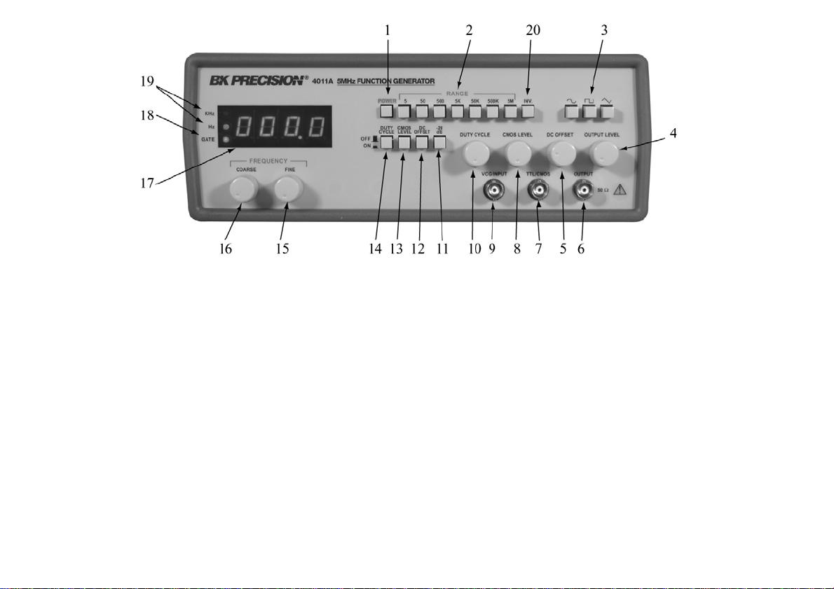
Figure 1. Model 4011A Controls and Indicators.
13. CMOS LEVEL Switch. When engaged, changes
the TTL signal to CMOS signal at the TTL/CMOS
jack.
14. DUTY CYCLE Switch. When engaged, enables
operation of DUTY CYCLE control (10).
15. FINE FREQUENCY Control. Vernier adjustment
of the output frequency for ease of setting frequency.
16. COARSE FREQUENCY Control. Coarse
adjustment of the output frequency from 0.1 to 1
times the selected range.
17. COUNTER DISPLAY. Displays frequency of internally
generated waveform.
18. GATE LED. Indicates when the frequency counter display is
updated. When the 50K through 5M ranges are selected, the
LED will flash 10 times per second (every 0.1 seconds).
When the 50 through 5K ranges are selected, the LED will
flash once every second and when the 5 range is selected, the
LED will flash every 10 seconds. As the LED turns off, the
display is updated.
19. Hz and KHz LED. Indicates whether the counter is reading
in Hz or kHz.
20 Inverter Switch
9
Page 10
OPERATING INSTRUCTIONS
g
p
The B+K Precision Model 4011A Function Generator is a
versatile instrument, capable of producing a variety of output
waveforms over a broad range of frequencies. To gain a working
familiarity with the unit, it is recommended that it be connected
initially to an oscilloscope, so that the effects of the various controls
on the output waveforms can be observed. Use this manual as
required for reference until becoming accustomed to the operating
procedures.
FREQUENCY AND WAVEFORM SELECTION
l. Initially, verify that the DUTY CYCLE (14), CMOS LEVEL
(13), DC OFFSET (12), -20dB (11) switches are in the OUT
position (released). This will produce a symmetrical waveform
unaffected by the other controls.
2. Plug the unit into an appropriate power source and turn it on by
engaging the POWER switch (1).
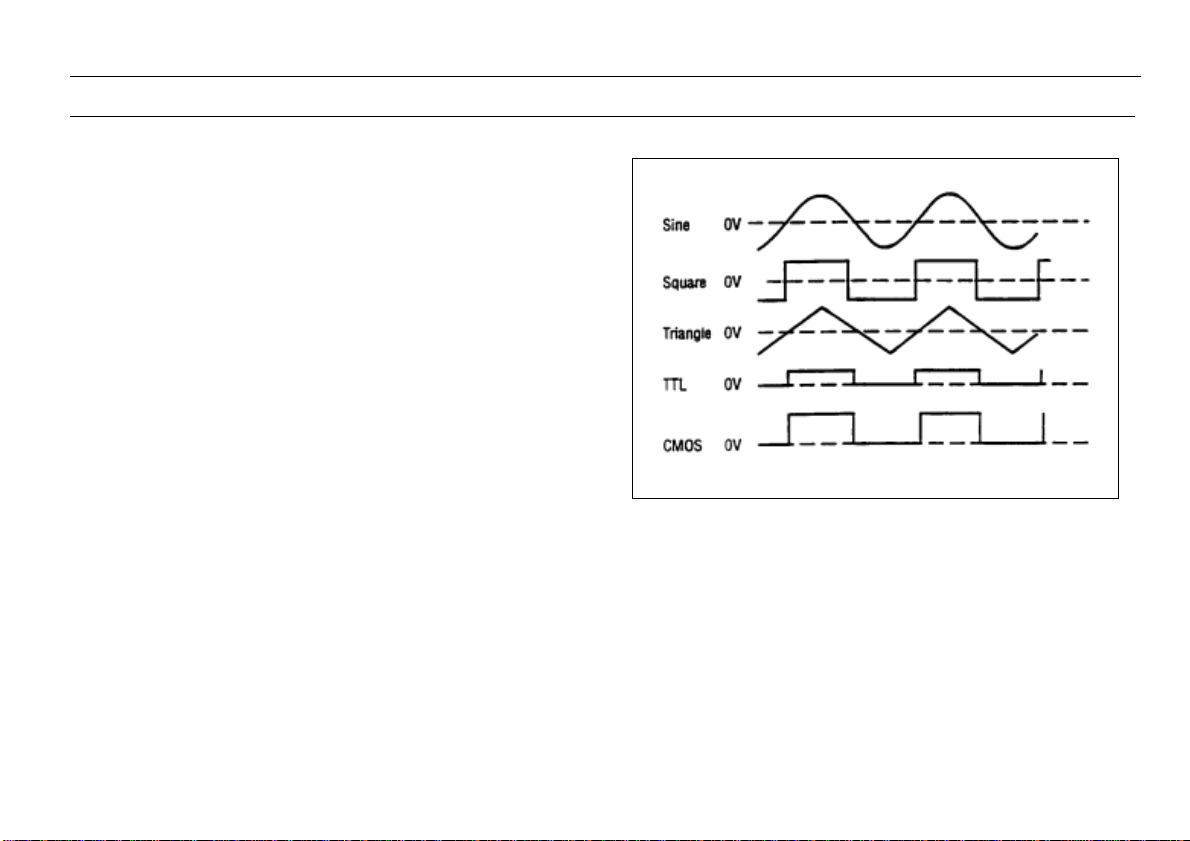
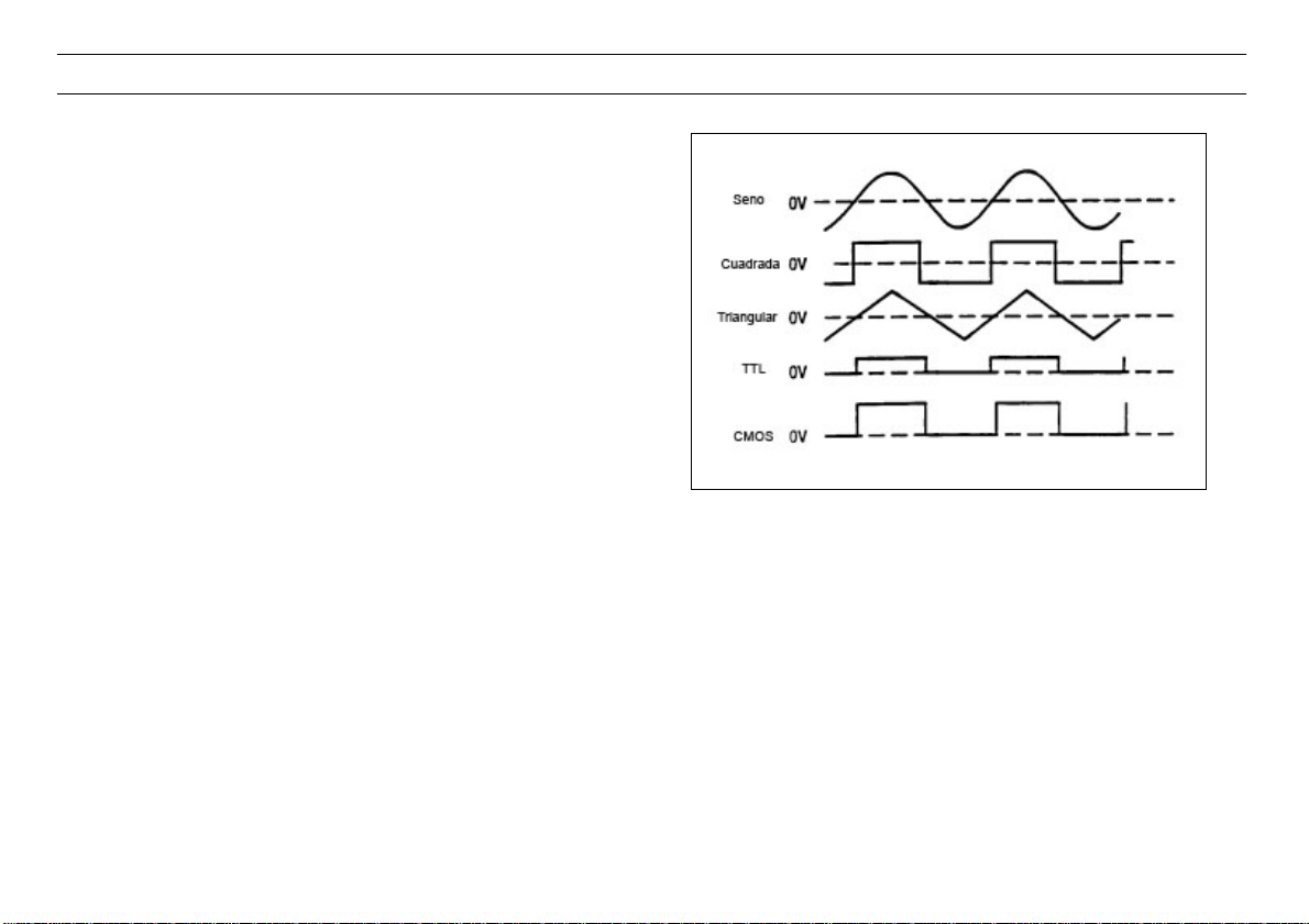
3. Select the desired waveform (SINE, SQUARE, or TRIANGLE)
by engaging one of the FUNCTION switches (3). Phase
relationships of the waveforms are shown in Fig. 2.
4. Select the frequency of the waveform by engaging one of the
RANGE switches (2). The output frequency is displayed, along
with the appropriate measurement units, kHz or Hz (19), on the
LED display.
5. Rotate the COARSE (16) frequency control to quickly set the
output frequency to the approximate desired value. The FINE
(15) frequency control can then be used to easily set the output
to the specific desired value. The frequency selected is available
at the OUTPUT jack (6). In addition, a digital signal, either TTL
or CMOS is available at the TTL/CMOS jack (7) (refer to the
“TTL/CMOS OUTPUT” section of this manual).
10
Figure 2. Output Waveform and Phase Relationshi
6. Adjust the amplitude of the output as desired using the
OUTPUT LEVEL control (4). Rotation of this control
varies the amplitude from maximum to 20dB below
maximum. An additional attenuation of -20dB is
available by pushing in the -20dB switch (11). The
attenuation factors can be combined for a total of -40dB.
The maximum si
nal level is 10V p-p (into 50 Ω).
Page 11
OPERATING INSTRUCTIONS
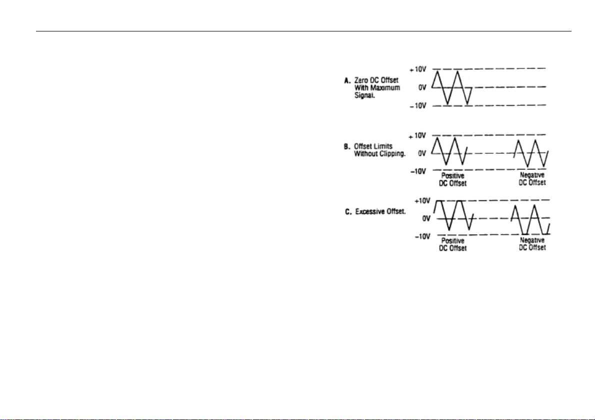
7. A superimposed DC component can be added to the output signal
by engaging the DC OFFSET switch (12) to enable operation of
the DC OFFSET control (5). Rotation of this control adds a
positive or negative DC component to the output signal. The DC
component introduced is independent of the OUTPUT LEVEL
control and can be varied by ±10 volts open circuited or ±5 volts
into 50Ω. The DC Offset does not affect the TTL/CMOS output
jack. The effect of DC OFFSET is shown in Fig. 3.
CONSIDERATIONS
1. l. Counterclockwise rotation of the COARSE frequency control
decreases the output frequency to approximately one-tenth of the
maximum for the range selected (10:1). For example, if the 50K
range is selected and the COARSE frequency control is set to
full counterclockwise, the output frequency is approximately
5kHz.
2. It is advisable to set the FINE frequency control to the
approximate center of its rotation before setting the COARSE
frequency control. This assures that the FINE control will not
reach its limit while trying to finalize the frequency setting.
3. The FINE frequency control provides approximately ±5%
frequency deviation from the COARSE control setting. This
provides vernier adjustment to easily set the frequency to a
precise value.
4. . When the 5Hz range is selected, the gate time is 10 seconds and
the display is updated once every 10 seconds. The result of a
frequency change will not be displayed until 10 seconds later.
Adjust the frequency in progressively smaller steps, waiting for
the display to update until the desired frequency is obtained.
5. When outputting square waves or when using the TTL output,
terminate the cable into 50Ω to minimize ringing. Also, keep
cables as short as possible.
11
Figure 3. Use of DC OFFSET Control
6. Remember that the output signal swing of the
generator is limited to ±10 volts open circuited or ±5
volts into 50Ω, and applies to the combined peak-topeak signal and DC offset. Clipping occurs slightly
above these levels. Fig. 3 illustrates the various
operating conditions encountered when using the DC
offset. If the desired output signal is large or if a large
DC offset is required, an oscilloscope should be used
to make sure that the desired signal is obtained without
undesirable clipping.
Page 12
OPERATING INSTRUCTIONS
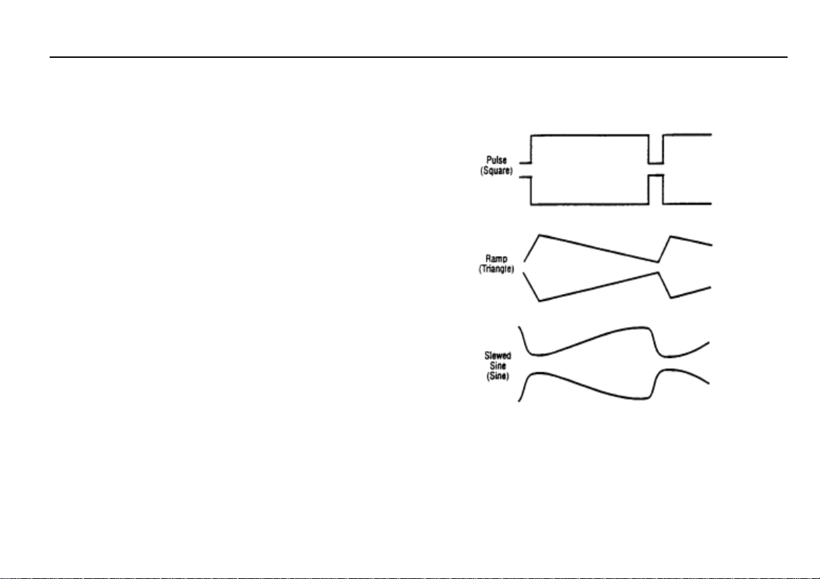
DUTY CYCLE CONTROL
The DUTY CYCLE control can be used to alter the
symmetry of the output waveform, to produce
waveshapes such as those shown in Fig. 4. For a
square wave, symmetry variation amounts to changing
the duty cycle (ratio of "high" to "low" time),
effectively converting the instrument into a pulse
generator. For a triangle wave, the result is a ramp, and
with a sine wave, a distorted waveshape called a
slewed sine is produced. The Model 4011A provides
for symmetry variation from 15% to 85%.
1. Select the waveform desired either SINE,
SQUARE or TRIANGLE.
2. Engage the DUTY CYCLE switch (14) and adjust
the DUTY CYCLE control (10) for the desired
waveshape. Clockwise rotation from center results
in an increase in square wave duty cycle, and
changes the sine and triangle waves as shown in
the top waveform of each pair of Fig. 4. Counterclockwise rotation results in the bottom waveform
in each pair.
3. Varying the duty cycle setting results in a slight
change in frequency. Adjust the COARSE and
FINE frequency controls as required.
Figure 4. Effects of Symmetry
Variation.
12
Page 13

OPERATING INSTRUCTIONS
TTL/CMOS OUTPUT
The TTL/CMOS output jack provides a fast rise time square wave
output. Either a fixed TTL or a variable CMOS output level is
available. The output is positive with respect to ground and can be
used as an external sync pulse for oscilloscopes or as a variable
frequency signal source for exercising logic circuits. Because of the
fast rise time of this output, cable length should be minimized to limit
ringing and overshoot.
1. Select the desired frequency range and adjust the frequency
controls as required. The OUTPUT LEVEL and DC OFFSET
controls have no effect on the signal at the TTL/CMOS jack.
2.
When the CMOS LEVEL switch (13) is OFF, a TTL signal is
output at the TTL/CMOS jack. Select a CMOS signal by
engaging the CMOS LEVEL switch and adjust the level of the
signal by rotating the CMOS LEVEL control (8).
VOLTAGE CONTROLLED FREQUENCY OPERATION
The Model 4011A can be operated as a voltage-controlled generator
by using an external control voltage applied to the VCG INPUT jack.
The externally applied voltage will vary the frequency which is
preselected by the range switches and the frequency controls. Applying
approximately +l0 V with the COARSE control at full clockwise
decreases the output frequency by about 100 times (a 100:1 ratio).
1. Select the desired frequency range and waveform.
2. Set the starting frequency with the COARSE control. Apply a
positive DC voltage to the VCG INPUT jack (9) to decrease the
frequency. A voltage from 0 to +10V will cause the frequency to
decrease by a factor of 100 if the COARSE frequency control is
set at maximum CW rotation. For example, if the starting
frequency is 500kHz, applying +10V will change the output
frequency to 5kHz.
13
3. To operate the function generator as a sweep generator,
apply a positive going ramp signal to the VCG INPUT
jack. As the ramp voltage increases, the frequency
decreases. The rate of sweep can be adjusted by varying
the frequency of the ramp signal.
4. Specific frequencies can be selected by applying a fixed
dc voltage to the VCG INPUT jack or the frequencies can
be stepped by applying a stepped dc voltage.
5. Do not apply more than ±15 volts (dc or dc + ac peak) to
the VCG INPUT jack. Inputs of more than 15 volts will
not cause any further shift in the frequency and could
cause damage to the generator.
OUTPUT PROTECTION CONSIDERATIONS
Use care when connecting the function generator output to a
signal injection point. Excessive voltage at the point of signal
injection of the function generator can cause internal damage.
Under normal operation, the generator output should never be
connected to an external voltage other than low dc values that
can be matched with the DC OFFSET control. The Model
4011A is overload protected so that shorting the output, even
continuously, will not cause damage. A fuse has been added in
series with the OUTPUT jack to help protect the instrument
from damage by connection to excessive external voltage.
Damage of this type usually occurs by accidentally
connecting the output of the function generator to a voltage in
the equipment under test. The following protective measures are
strongly recommended:
1. The user should understand the equipment under test well
enough to identify valid signal injection points (i.e., the
base of a transistor, a logic input of a gate, etc.). The
voltage at valid signal injection points is rarely high enough
to damage the instrument.
Page 14

OPERATING INSTRUCTIONS
2. If in doubt about the safety of a signal injection
point, measure the voltage present at the intended
point of signal injection before connecting the
function generator output to that point.
3. When applying the main output of the function
generator to a circuit point containing a dc level,
adjust the DC OFFSET control so that the dc level
at the main output matches the circuit voltage.
4. Connect the TTL output only to TTL-level circuits.
Connect the CMOS output only to CMOS circuits.
Measure the Vcc of the circuit under test and adjust
the CMOS LEVEL control as instructed in the
manual.
5. When the function generator is used by students or
other inexperienced users, the circuit of Fig. 5
could be added into your TTL output probe or test
clip set. It will protect the TTL output of the
generator against external voltages up to ±20 volts.
Figure 5. Circuit for Protection of TTL Output.
FUNCTION GENERATOR APPLICATIONS
GUIDEBOOK
B+K Precision offers a “Guidebook to Function
Generators” which describes numerous applications for this
instrument, including hook-up details. It also includes a
glossary of function generator terminology and an
explanation of function generator circuit operation. It may
be downloaded off our website at www.bkprecision.com
.
14
Page 15

MAINTENANCE
The following instructions are for use by qualified service
personnel only. To avoid electrical shock, do not perform
servicing other than contained in the operating instructions
Remember that ac line voltage is present on line voltage input
circuits any time the instrument is plugged into an ac outlet, even
if turned off. Always unplug the function generator before
FUSE REPLACEMENT
1. Locate the fuse holder on the input line receptacle.
2. Remove the fuse holder and replace the fuse with an
equal value fuse
unless you are qualified to do so.
performing service procedures.
WARNING
INSTRUMENT REPAIR SERVICE
Because of the specialized skills and test
equipment required for instrument repair and
calibration, many customers prefer to rely upon
B+K PRECISION for this service. We maintain a
network of B+K PRECISION authorized service
agencies for this purpose. To use this service, even
if the instrument is no longer under warranty, follow
the instructions given in the WARRANTY
SERVICE INSTRUCTIONS portion of this manual.
There is a nominal charge for instruments out of
warranty.
15
Page 16

CUSTOMER SUPPORT
1-800-462-9832
B+K Precision offers courteous, professional technical support before and after the sale of their test instruments. The following services are
typical of those available from our toll-free telephone number:
Technical advice on the use of your instrument.
Technical advice on special applications of your instrument.
Technical advice on selecting the best instrument for a given task.
Information on optional accessories for your instrument.
Information on instrument repair and recalibration services.
Replacement parts ordering.
Availability of service publications.
Information on other B+K Precision instruments.
Requests for a new B+K Precision catalog.
The name of your nearest B+ K Precision distributor.
Call toll-free 1-800-462-9832
Monday through Thursday, 8:00 A.M. to 5:00 P.M, Friday 8:00 A.M. TO 11:30 A.M.
Pacific Standard Time
(Pacific Daylight Time summer)
16
Page 17

Service Information
Warranty Service: Please return the product in the original packaging with proof of purchase to the address below. Clearly state in writing
the performance problem and return any leads, probes, connectors and accessories that you are using with the device.
Non-Warranty Service: Return the product in the original packaging to the address below. Clearly state in writing the performance problem
and return any leads, probes, connectors and accessories that you are using with the device. Customers not on open account must include
payment in the form of a money order or credit card. For the most current repair charges please visit www.bkprecision.com
“service/repair”.
Return all merchandise to B&K Precision Corp. with pre-paid shipping. The flat-rate repair charge for Non-Warranty Service does not include
return shipping. Return shipping to locations in North American is included for Warranty Service. For overnight shipments and non-North
American shipping fees please contact B&K Precision Corp.
B&K Precision Corp.
22820 Savi Ranch Parkway
Yorba Linda, CA 92887
www.bkprecision.com
714-921-9095
Include with the returned instrument your complete return shipping address, contact name, phone number and description of
problem.
and click on
17
Page 18

Limited Two-Year Warranty
B&K Precision Corp. warrants to the original purchaser that its products and the component parts thereof, will be free from defects in
workmanship and materials for a period of two years from date of purchase.
B&K Precision Corp. will, without charge, repair or replace, at its option, defective product or component parts. Returned product must be
accompanied by proof of the purchase date in the form of a sales receipt.
To obtain warranty coverage in the U.S.A., this product must be registered by completing a warranty registration form on
www.bkprecision.com
Exclusions: This warranty does not apply in the event of misuse or abuse of the product or as a result of unauthorized alterations or
repairs. The warranty is void if the serial number is altered, defaced or removed.
B&K Precision Corp. shall not be liable for any consequential damages, including without limitation damages resulting from loss of use.
Some states do not allow limitations of incidental or consequential damages. So the above limitation or exclusion may not apply to you.
This warranty gives you specific rights and you may have other rights, which vary from state-to-state.
B&K Precision Corp.
22820 Savi Ranch Parkway
Yorba Linda, CA 92887
www.bkprecision.com
714-921-9095
within fifteen (15) days of purchase.
MODEL 4011A DATE PURCHASED_______________________
18
Page 19

TEST INSTRUMENT SAFETY
(continued from inside front cover)
6. Some equipment with a two-wire ac power cord, including some with polarized power plugs, is the “hot chassis” type. This
includes most recent television receivers and audio equipment. A plastic or wooden cabinet insulates the chassis to protect the
customer. When the cabinet is removed for servicing, a serious shock hazard exists if the chassis is touched. Not only does this
present a dangerous shock hazard, but damage to test instruments or the equipment under test may result from connecting the
ground lead of most test instruments to a “hot chassis”. To test “hot chassis” equipment, always connect an isolation transformer
between the ac outlet and the equipment under test. The B+K Precision Model TR-110 or 1604 Isolation Transformer, or Model
1653 or 1655 AC Power Supply is suitable for most applications. To be on the safe side, treat all two-wire ac equipment as “hotchassis” unless you are sure it has an isolated chassis or an earth ground chassis.
7. On test instruments or any equipment with a 3-wire ac power plug, use only a 3-wire outlet. This is a safety feature to keep the
housing or other exposed elements at earth ground.
8. Never work alone. Someone should be nearby to render aid if necessary. Training in CPR (cardio-pulmonary resuscitation) first
aid is highly recommended.
19
Page 20

SEGURIDAD DE EL INSTRUMENTO DE PRUEBA
PRECAUCIONES
Use normal de equip de probe tee espouse a caret cantina de peligro por un choque eléctrico porque revisiones son algunas
veces hechas donde hay alto voltaje descubierto. Un choque eléctrico que cause 10 milliamps pasar a través del corazón
pararía la mayoría de los corazones humanos. Voltaje tan bajo hasta 30 voltios dc o ac rms podría ser considerado peligroso
porque puede producir una corriente letal bajo ciertas condiciones. Voltajes mas altos pueden ser aun más peligrosos. Tus
hábitos normales de trabajo deben de incluir todas las practicas aceptadas para prevenir contacto con alto voltaje descubierto, y
dirigir corriente lejos del corazón en caso de contacto accidental con un alto voltaje. Observe las siguientes medidas de
seguridad:
1. No se expone a alto voltaje sin necesidad. Remueva la caja y tapas solo cuando sea necesario. Apague el equipo cuando
haga conexiones en circuitos de alto voltaje. Descargue los capacitadotes de alto voltaje después de remover poder.
2. Si es posible, familiarícese usted mismo con el equipo que va ha ser revisado y los lugares de los puntos de alto voltaje.
Pero, también recure que alto voltaje puede aparecer en puntos inesperados en equipo defectuoso.
3. Use un piso de material insuflado o un tapete de piso insuflado largo para caminar en él, y una superficie de trabajo
insuflada en la cual pueda poner el equipo; y asegurarse que las superficies no esten humedas o mojadas.
4. Use la técnica comprobada por el tiempo de “una mano en la bolsa” cuando este usando una sonda de instrumento. Sea
particularmente cuidadoso de evitar conectar un objeto de metal que pueda proveer un buen camino de regreso a tierra.
5. Cuando revise equipo conectado a ca, recure que la línea de voltaje ca es usualmente presente en algunos circuitos
encendidos de entrada tal como el switch de encendido y apagado, fusibles, transformadores de poder, etc. cualquier
tiempo que el equipo este conectado a una enchufe de ca, aun si el equipo esta apagado.
(continuó la cubierta de espalda)
20
Page 21

MANUAL DE INSTRUIONES
MODELO 4011A
5MHz GENERADOR DE FUNCIONES
CON DIGITOS INDICADOR
22820 Savi Ranch Parkway • Yorba Linda, CA 92887-4610
21
Page 22

TABLA DE CONTENDIDO
SEGURIDAD DEL INSTRUMENTO DE PRUEBA
INTRODUCION ...................................................................... 23
ESPECIFICACIONES............................................................. 25
CONTROLESE INDICADORES............................................ 26
INSTRUCCIONES DE OPERACIÓN.................................... 28
Selección de frecuencia y forma de onda ................................. 28
Consideraciones .......................................................................29
Control de ciclo de servicio...................................................... 30
Salida para TTL/CMOS ........................................................... 31
Operación de voltaje controlada frecuencia ..........................31
Consideraciones de protección de salida...............................31
Guía de aplicaciones del generador de funciones..................32
MANTENIMLENTO ...........................................................33
Reemplazo de fusible............................................................33
Servicio de reparación del instrumento.................................33
Servicio al cliente..................................................................33
SOPORTE AL CLIENTE.....................................................34
Información de Servicio...............................................35
Garantía Limitada de Dos Anos...................................36
22
Page 23

INTRODUCCIÓN
El B & K Precision modelo 4011A Funcion generador es una
versátil fuente de señales cual combina varias funciones en una
unidad- generador de formas de onda, generación de pulso
(atravez de simetría variable), y barrido de frecuencia.
Adicionalmente, el instrumento provee la conveniencia adicional
de un incluido contador de frecuencia. Esto permite mas precisa
determinacion de la frecuencia de salida que se posible con un
simple calibrado medidor. Controles de ajuste grueso y fino
permiten ajuste de precision de la salida de frecuencia. La alta
estabilidad asegura que la frecuencia de la salida no mandila.
Con esta versatilidad, la unidad tiene un amplio numero de
aplicaciones en ambos analogo y digital electronica en los
campos de ingeniería, manufactura, servicio, educación y
recreación.
El corazón de el generador de funciones es un VCG (voltajecontrolado generador) que produce ondas de seno, cuadradas y
triangulares desde los 0.5Hz hasta 5MHz rango. Esto en compasa
subaudible, sonido, untrasonido, ultrasonico y RF aplicaciones.
Un continuamente variable compensación de cd permite a la
salida ser injectada dentro de circuitos al el correcto nivel medio.
El generador de barrido ofrece linear y logarítmico barrido con
un rango variable de barrido y tiempo de barrido ajustable. El
tablero de control delantero permite el ajuste de comienzo y alto
de frecuencias.
Operación estallido permite la salida a ser bloqueada, por una
interna, ajustable señal o por una señal aplicada externamente.
simetría variable de la onda de forma de salida convierte el
instrumento en un generador de pulsos capaz de generar ondas
rectangulares o impulsos, rampas,o diente de cerrucho ondas, y
ondas inclinadas de seno.
En adicion a las caracteristicas mencionadas, un voltaje externo
puede ser usado para controlar la frecuencia de operacion.
23
Page 24

ESPECIFICACIONES
CARACTERÍSTICAS DE FRECUENCIA
Formas de onda:
seno,cuadrada,triangular±-Impulso,±rampa
Rango:
0.5Hz a 5MHz en 7 rangos
Resolución
4 dígitos
Afinación rango:
gruesco 10:1, Fino+/--5% de posición gruesa
Variable ciclo de servicio:
15:85:15 continuamente variable
Modos de operación:
normal,barrido,VCG,AM,FM estallido
Estabilidad de frecuencia:
la salida combiara menos que 0.09% sobr 15 minutes
después de 1 hora de caletamlento
CARACTERÍSTICAS DE SALIDA
Impederica:
50 OHM +/- 10%
Nivel:
20Vp-p circuito abierto,10Vp-p dentro de
50 OHM a 10MHz
Amplitud control:
Variable 20db rango tipico
Atenuación:
-20db+/-1db
DC compensación :
Preset: ±0.1V typico
Variable ±10V circuito abierto ,±5V Dentro 50Ω
ONDA SENO
Distorsión:
≤3% Tipicol a 1KHz
Flames
≤5%(.45DB)
ONDA CUADRADA
Simetría :
≤2% 0.5Hz a 100KHz
Tiempo de elevación
≤120ns
ONDA TRIANGUAR
Linearidad:
≥98% a 100KHz
24
Page 25

ESPECIFICACIONES
SALIDA TTL
Nivel 0.8V a 4V +0.5Vp-p
Tiempo de elevación ≤20ns
Ciclo de servicio: 50% tipico
CMOS SALIDA
Max frecuencia: 2Mhz
Nive: 4V a 14 V +/-0.5Vp-p
continuamente variable
Tiempo de elevación ≤ 20nS
VCG(GENERADOR DE VOLTAJE CONTROLADOR)
ENTRADA
Voltaje de entrada :0-10V ±1V causa un 100:1
cambio de frecuencia
Impendencia :10kOhm ±5%
NOTA: Las especificaciones y la información están conforme a cambio sin el aviso de B&K Precision Corp. Por favor visite
www.bkprecision.com
para las especificaciones más corriente y información de nuestros productos.
CONTADOR DE FRECUENCIA
Precision:
precisoin de tiempo base ± 1 count
precisoin de tiempo base
+/- 10 ppm (23`C ± 5`C)
Pantalla
4 digitos LED
FUENTE DE PODER
120/230 VAC ± 10% 50/60hz selecionable bricandor
DEMESIONE
4.5” x 10.575” x 11.75” (114 x 264 x 298 mm)
PESO
4 LB (1.8 kg)
ACCESORIOS
Cable de salida BNC a clips de cocodrilo
Manual de instrucción
inarno
25
Page 26

CONTROLES E INDICADORES
PANEL DELANTERO (Vea a al Fig 1)
1. INTERRUPTOR DE ENCENDIDO. Enciende y apaga el
poder.
2. SWITCH DE RANGO. Selecciona el rango de la frecuencia de
salida. 7 rangos de 5Hz a 5MHz. El switch indica la máxima
frecuenta de rango y es ajustado con el control grueso de
frecuencia a 0.1 veces el máximo. Por ejemplo, si el rango de
500KHz es seleccionado, la salida de frecuencia puede ser
ajustada de 50KHz a 500KHz
3. SWITCH DE FUNCIONES. Selecciona seno, cuadrada,
triangular forma de onda al jack de salida.
4. CONTROL DE NIVEL DE SALIDA. Controla la amplitud de
la senal al jack de salida. El nivel de salida puede ser
disminuido por aproximadamente 20 dB con este control
5. CONTROL DE LA COMPENSACIÓN CD. Activado por el cd
compensación switch (12). Rotación en la dirección de las
manecillas de el reloj desde el centro cambia la compensación
de cd en la dirección positiva cuando rotación en contra de las
manecillas del reloj desde el centro cambia la compensación de
cd en la dirección negativa.
6. JACK DE SALIDA. Forma de onda seleccionada por el switch
de funciones como también como el sobre impuesto voltaje de
compensación cd esta disponible en este jack
7. TTL/CMOS jack. TTL o CMOS onda cuadrada , dependiendo
en la posición de el switch (13) de el nivel CMOS, sale de este
jack. Esta salida es independiente del NIVEL DE SALIDA y
.
8. CONTROL DE NIVEL CMOS. Girando este control en la
dirección de las manecillas de el reloj aumenta la amplitud
de la senal CMOS a el TTL/CMOS jack.
9. VCG jack de entrada. Jack es el voltaje controlado generador
de salida y permite control externo de el generador de la
frecuencia de salida por una entrada de voltaje cd en este
jack. Un voltaje positivo disminuirá la frecuencia.
10. CONTROL DE EL CICLO DE SERVICIO. Activado por el
ciclo de servicio switch(14). Rotación desde la posición
central ajusta el ciclo de servicio de la senal de la salida
principal.
11. –20 DB SWITCH. Cuando accionado, la senal al jack de
salida es atenuada por –20 dB.
12. SWITCH DE COMPENSACIÓN DE CD. Cuando
accionado, permite la cooperación de el control de
compensación de cd(5).
13. SWITCH DE NIVEL DE CMOS. Accionado, cambia la
senal TTL a senal CMOS a el TTL/CMOS jack y permite la
cooperación de el control de nivel CMOS.
14. INTERRUPTOR DE CICLO DE SERVICIO. Cuando
enganche, permite la operación del control de CICLO de
servicio(10).
15. Control FINO DE FRECUENCIA. Ajustes de vernier de la
frecuencia de salida para un ajuste fácil de frecuencia.
26
Page 27

CONTROLES E INDICADORES
16. Control GRUESO DE FRECUENCIA. Ajuste grueso de la frecuencia de salida de 0.1 a 1 veces el rango seleccionado.
17. PANTALLA DE EL CONTADOR. Muestra la frecuencia de formas de onda generadas internamente.
18. LED PUERTA. Indica cuando la pantalla de el contador cambia. Cuando los 50KHz a 5MHz rangos son
seleccionados, el LED relampaguea 10 veces por segundo (cada 0.1 segundos). Cuando el 50 hasta 5K rango es seleccionado la LED
relampaguea una vez cada segundo y cuando el rango 5 es seleccionado, la LED relampaguee cada 10 segundos. Cuando la LED se apaga, la
pantalla cambia.
19. Hz y KHz LED. Indica si el contador esta leyendo Hz o kHz.
20. Botón Invertido. Invertían la señal de salida.
1 2 20 3
4
19
18
27
16 15 14 13 12 11 10 9 8 7 5 6
Page 28
INSTRUCCIONES DE OPERACION
El B&K Precison Modelo 4011A Barrido/Funcion generador es
un instrumento versátil, capaz de producir una variedad de
formas de onda a través un ancho rango de frecuencias. Para
ganar una buena familiaridad con esta unidad, es recomendable
que este conectada inicialmente a un osciloscopio, para que los
efectos de los varios controles en las formas de onda que son
generadas puedan ser observadas. Use este manual como se
requiera para referencia hasta que llegue a acostumbrarse a los
procedimientos de cooperación.
SELECCION DE FRECUENCIA Y FORMA DE ONDA
1. Inicialmente, verifique que el ciclo de servicio (14), Nivel
CMOS(13), CD ajuste(12), -20dB(11), y BARRIDO
EXT/INT (12), switches están en la posición abierta. Esto
le producirá una onda de forma simétrica no afectada por el
generador de barrido y otros controles.
2. Enchufe la unidad en la apropiada fuente de energía y
préndalo oprimiendo el switch de POWER (1.
3. Seleccione la onda de forma deseada (seno, cuadradazo
triangulo) oprimiendo uno de los switches de la
FUNCION(3). Relaciones de fase de las formas de onda
son mostradas en la figura 2.
4. Seleccione la frecuencia de la onda de forma oprimiendo
uno de los switches de rango(2). La frecuencia de salida es
mostrada, junto con las unidades de medida apropiadas,
KHz,0 Hz (19), on el LED indicador.
5. Mueva el GRUESO (16) control de frecuencia para
rápidamente controlar la frecuencia de salida al valor deseado
aproximado. El FINO(15) ajustes de vernier de la frecuencia
de salida para un ajuste fácil de frecuencia. La frecuencia
seleccionada esta disponible at the OUTPUT jack (6). En
adición, una senal digital, sea TTL o CMOS esta disponible
a los TTL/CMOS jack (7) (referir a los “TTL/CMOS
OUTPUT” sección de este manual
Fig 2
6. Ajuste la amplitud de la salida como desee usando el
OUTPUT LEVEL (Nivel de salida) control (4).
Rotación de este control varia la amplitud desde el
máximo hasta 20dB debajo del máximo. Una
atenuación adicional de –20dB esta disponible
oprimiendo el –20dB switch(11). Los factores de
atenuación pueden ser combinados por un total de –
40dB. El máximo nivel de senal es 10V p-p (dentro de
50 ).
28
Page 29

INSTRUCCIONES DE OPERACION
5. Un CD componente puede ser sumado at la senal de salida
oprimiendo en la compensación de CD switch (12) para activar la
cooperación del COMPENSACION CD control (5). Rotación de
este control suma un positivo o negativo compensación CD
componente a la senal de salida. El componente CD introducido es
independiente de el control de el NIVEL DE SALIDA y puede ser
variado por +/- 10 voltios circuito abierto o +/- voltios atraves de 50
ohms. La compensación de CD no afecta el TTL/CMOS salida
jack. El efecto de la COMPENSACION CD is mostrado en Fig. 3.
CONSIDERACIONES
1. Contra el reloj rotación del control de GRUESO frecuencia
disminuye la frecuencia de salida hasta aproximadamente undeceavo del máximo rango seleccionado. (10:1). Por ejemplo, si el
50K rango es seleccionado y el de frecuencia GRUESO es puesto a
toda la rotación contra el reloj dirección., La frecuencia de salida is
aproximadamente 5KHz.
2. Es recomendado poner el control fino de frecuencia a
aproximadamente el centro de su rotación antes del ajustamiento
del GRUESO control de frecuencia. Esto asegura que el control
FINO no alcanzara su limite cuando se trate de finalizar el arreglo
de la frecuencia.
3. El control fino de frecuencia provee aproximadamente +/- 5%
desviado de frecuencia desde el GRUESO control ajuste. Esto
provee vernier ajustes para fácilmente poner la frecuencia a un
valor preciso.
4. Cuando el 5Hz rango is seleccionado, el tiempo de la puerta es 10
segundos y el indicador es renovado una vez cada 10 segundos. El
resultado de un cambio de frecuencia no será indicado hasta 10
segundos mas tarde. Ajuste la frecuencia en progresivamente pasos
más pequeños, esperando por el indicador a cambiar hasta que la
frecuencia deseada es obtenida.
5. Cuando generando ondas cuadradas o cuando usando la salida de
TTL, termine el cable en 50 ohms para disminuir resonación.
También, use cables tan cortos como sea posible.
29
Figura 3. Uso del control de compensación DC
6. Recuerde que la variación de la senal de salida de
el generador esta limitado a +/- voltios circuito
abierto o +/- voltios en 50 ohms, y aplica a el
combinado pico-a –pico senal y la compensación
deCD . Truncado ocurre ligeramente arriba de estos
niveles. Fig. 3 ilustra las varias condiciones de
cooperación encontradas cuando usando el ajuste
CD. Si la senal de salida es larga o si una
compensación de CD es requerida , un osciloscopio
deberá de ser usado para asegurar que la senal
deseada es obtenida sin el truncado no deseado.
Page 30

INSTRUCCIONES DE OPERACION
CONTROL DE CICLO DE SERVICIO
El CICLO DE SERVICIO control puede ser usado para
alterar la simetría de la forma de onda de salida, para
producir ondas de forma tal como esas mostradas en Fig. 4.
Por una onda cuadrada, la cantidad de variación de simetría
a cambiar el ciclo servicio (factor de “alto” a “bajo”
tiempo), efectivamente convirtiendo el instrumento en un
generador de pulsos. Para una onda triangular, el resultado
es una rampa, y con una onda de seno, una onda de forma
distorsionada llamada seno inclinado es producida. El
Modelo 4011A provee por la variación de simetría desde
15% hasta 85%.
1. Seleccione la onda de forma deseada sea SENO,
CUADRADA, o TRIANGULAR.
2. Enganche el CICLO DE SERVICIO switch (14) y
ajuste el CICLO DE SERVICIO control (10) para la
deseada onda de forma. Con el reloj rotación desde el
centro resulta en un incremento en una onda cuadrada,
y cambios en las ondas de seno y triangulo es
mostradas en la forma de arriba de cada par en Fig.4.
Contra-el-reloj rotación resulta en las ondas de forma
de abajo en cada par.
3. Variaciones del ciclo de servicio ajustamientos resulta
en un ligero cambio en frecuencia. Ajuste el GRUESO
y FINO controles de frecuencia como sea requerido.
Figura 4 Efectos de variación desinctraima
30
Page 31

INSTRUCCIONES DE OPERACION
TTL/CMOS SALIDA
El TTL/CMOS jack de salida provee un rapido tiempo de subido onda
cuadrada de salida. Sea un fijo TTL o un variable CMOS nivel de
salida esta disponible. La salida es positiva con respecto a tierra y
puede ser usada como un pulso sync para osciloscopios o como una
senal variable de frecuencia para ejercitando circuitos de logica. Por el
rapido tiempo de subida de esta salida, lo largo de el cable debe de ser
minimizado para limitar riesonaciony sobretiro.
1. Seleccione el rango de frecuencia deseado y ajuste los controles de
frecuencia como sea requerido. El OUTPUT LEVEL (nivel de
salida) y DC OFFSET (compensacion de salida CD) controles no
tienen efecto en la senal a el TTL/CMOS jack.
2. Cuando el CMOS LEVEL (nivel) switch (13) es desenganchado,
una TTL senal es producida a el TTL/CMOS jack. Seleccione una
CMOS senal accionando el CMOS LEVEL (nivel) switch y
ajustando el nivel de la senal girando el CMOS LEVEL (nivel)
control (8).
OPERACION DE LA VOLTAJE CONTROLADA FRECUENCIA
El modelo 4011A puede ser operado como un voltaje-controlado
generador cuando se usa un externo controlado voltaje aplicado al
VCG/MOD INPUT (entrada) jack . El externamente aplicado voltaje
variara la frecuencia cual es preseleccionada por los switches de rango y
los controles de frequencia. Aplicando aproximadamente +10V con el
GRUESO control a la vuelta completa con ladireccion del reloj
disminuye la frecuencia de salida por cerca de 100 veces (un factor
de100:1 ).
1. Seleccione el rango de frequencia deseado y la forma de onda
2. Ajuste la frecuencia de comienzo con el GRUESO control. Aplique
un voltaje CD positivo a el VCG INPUT jack(9) para disminuir la
frecuencia. Un voltaje de 0 a +10 V hara que la frecuencia
disminuya por un factor de100 si el GRUESO frecuencia control is
arreglado a maximo CW (contra el reloj)rotacion. Por ejemplo, si
la frecuencia de comiezo es 500 KHz, aplicando +10 V cambiara la
frecuencia de salida a 5KHz.
3. Para usar el generador de funciones como un generador de
barrido, aplique un positivo-dirijido senal de rampa al el VCG
INPUT jack de entrada. Cuando el voltaje de rampa aumenta,
la frequencia disminuye. La velocidad de barrido puede ser
ajustada variando la frecuencia de la senal de rampa.
4. epecificas frecuencias pueden ser seleccionadas aplicando un
voltaje cd fijo al el VCG INPUT jack o las frecuencias pueden
ser escalonado aplicando un escalonado voltaje cd .
5. No aplique mas de +/- 15 voltios (cd o cd + ca pico) a el VCG
INPUT jack. Entradas de mas de 15 voltios no causarian
nada mas cambio el la frecuencia y podria ocasionar dano a el
generador.
CONSIDERACIONES DE PROTECCION DE SALIDA
Use cuidado cuando conecte la salida de el generador de funciones
a un punto de injection de senales. Voltaje excesivo al el punto de
injeccion de el generador de funciones puede causar dano interno.
Bajo operacion normal, la salida de el generador nunca debe de ser
conectada a un voltaje externo otro que bajo cd valores que puedan
ser igualados con el COMPENSACION DE CD control. El
Modelo 4011A esta protegido contra sobrecargos que aunque
aparezca un corto circuito en la salida, aunque continuamente, no
causaria dano. Un fusible ha sido anadido en series con el jack de
SALIDA para ayudar a proteger el instrumento de dano por una
coneccion a voltaje excesivo externo.
Dano de este tipo usualmente ocurre por accidentalmente
conectando la salida de el generador de funciones a un voltaje en el
equipo bajo prueba. Las siguientes medidas de proteccion son
fuertemente recomendadas:
1. El usuario debe de entender el equipo bajo prueba lo suficiente
bien para identificar validos puntos de injeccion de senales
31
(e.g. la base de un transistor, una entrada logica de una
compuerta, etc.) El voltaje en un valido punto de injeccion de
senales es raramente suficiente alto para danar al instrumento.
Page 32

INSTRUCCIONES DE OPERACION
2. Si en duda acerca de la seguridad de un punto de
injeccion de senales, mida el voltaje presente en el
punto de injeccion de senales intentado antes de
connectar la salida de el generador de funciones a este
punto.
3. Cuando aplique la salida principal de el generador de
senales a un punto de un circuito que contenga un
nivel de cd, ajuse el CD AJUSTE control para que el
nivel de cd a la salida principal iguale el voltaje de el
circuito.
4. Connecte la salida de TTL solo a circuitos de TTL-
nivel. Conecte la salida de CMOS solo a circuitos
CMOS. Mida el Vcc de el circuito bajo prueba y
ajuste el NIVEL CMOS control como sea instruido en
el manual.
5. Cuando el generador de funciones es usado por
estudiantes u otros usuarios sin experiencia, el
circuito mostrado en Fig. 5 puede ser anadido en su
sonda de la salida TTL o el ajuste de clip de prueba.
Esto protegera la TTL salida de el generador encontra
de voltajes externos hasta +/- 20 voltios.
Figura 5 Salida deTTL generador de
funciones Tierra al circuito
LIBRO GUIA DE APLICACIONES DE EL GENERADOR
DE FUNCIONES
B &K Precision ofrece una “Guía del Generador de
Funciones” que describe numerosas aplicaciones de este
instrumento, incluyendo detalles de conexión. También
incluye un glosario de la terminología del generador de
funciones y una explicación de la operación de su circuito.
Puede ser descargado gratis de nuestra Web site en
www.bkprecision
32
Page 33

Las siguientes instrucciones son para uso solo por personal
de servico calificado. Para evitar choque electrico, no haga
servicio otro que el contenido en las instrucciones de
operacion a menos que este calificado para hacerlo.
Recuerde que linea de voltaje de ca esta presente sobre la
linea de voltaje de entrada de los circuitos a cualquier tiempo
que el instrumento esta enchufado en un enchufe de ca, hasta
si esta apagado. Siempre desenchufe el generador de
funciones antes de hacer procedimientos de servicio.
PRECAUCION
MANTENIMIENTO
REEMPLAZO DE FUSIBLES
1. Localice el sostenedor de fusible en la linea de entrada.
2. Quite el sostenedor del fusible y dubstituya el fusible por
un fusible de valor egual.
SERVICIO DE REPARACION DEL INSTRUMENTO
Debido a las especializadas habilidades y equipo de prueba
requerido para la reparación y calibración del instrumento,
muchos clientes prefieren depender en B & K Precisión para
este servicio. Nosotros mantenemos una red de agencias de
servicio autorizadas para este propósito. Para usar este
servicio, aún si el instrumento ya no esta bajo garantía, siga
las instrucciones en la parte de INSTRUCCIONES DE
SERVICIO DE GARANTIA de este manual. Hay un cargo
nominal por instrumentos fuera de garantía.
33
Page 34

SOPORTE AL CLIENTE
1-800-462-9832
b+k Precision ofrece soporte técnico profesional y cortés antes y después de la venta de sus equipos de prueba. Los siguientes son servicios
típicos de los disponibles de nuestro teléfono sin carga:
• Asesoría técnica sobre el uso de su instrumento
• Asesoría técnica sobre aplicaciones especiales de su instrumento
• Asesoría técnica para escoger el mejor instrumento para una tarea específica
• Información sobre accesorios opcionales para su instrumento
• Información sobre servicios de reparación y recalibración
• Pedidos de partes de reemplazo
• Disponibilidad de publicaciones de servicio
• Información sobre otros instrumentos de B+K Precision
• Solicitudes de catálogos de B+K Precision
• El nombre de su distribuidor más cercano
Llame sin cargo 800-462-9832
34
Page 35

Información de Servicio
Servicio de Garantía: Por favor regrese el producto en el empaquetado original con prueba de la fecha de la compra a la dirección debajo.
Indique claramente el problema en escritura, incluya todos los accesorios que se estan usado con el equipo.
Servicio de No Garantía: Por favor regrese el producto en el empaquetado original con prueba de la fecha de la compra a la dirección
debajo. Indique claramente el problema en escritura, incluya todos los accesorios que se estan usado con el equipo. Clientes que no tienen
cuentas deben de incluir pago en forma de queque, orden de dinero, o numero de carta de crédito. Para los precisos mas corriente visite
www.bkprecision.com
Vuelva toda la mercancía a B&K Precision Corp. con el envío pagado por adelantado. La carga global de la reparación para el servicio de la
No-Garantía no incluye el envío de vuelta. El envío de vuelta a las localizaciones en norte americano es incluido para el servicio de la
garantía. Para los envíos de noche y el envío del no-Norte los honorarios americanos satisfacen el contacto B&K Precision Corp.
B&K Precision Corp.
22820 Savi Ranch Parkway
Yorba Linda, CA 92887
www.bkprecision.com
714-921-9095
Incluya con el instrumento la dirección de vuelto para envío, nombre del contacto, número de teléfono y descripción del problema.
y oprime “service/repair”.
35
Page 36

Garantía Limitada de Dos Anos
B&K Precision Corp. Autorizaciones al comprador original que su productos y componentes serán libre de defectos por el periodo de dos
anos desde el día en que se compro.
B&K Precision Corp. sin carga, repararemos o sustituir, a nuestra opción, producto defectivo o componentes. Producto devuelto tiene que ser
acompañado con prueba de la fecha del la compra en la forma de tres recibo de las ventas.
Para obtener cobertura en los EE.UU., este producto debe ser registrado por medio de la forma de registro en www.bkprecision.com
quince (15) días de la compra de este producto.
Exclusiones: Esta garantía no se aplica en el evento de uso en error o abuso de este producto o el resultado de alteraciones
desautorizado o reparaciones. La garantía es vacía si se altera, se desfigura o se quita el número de serie.
B&K Precision Corp. no será obligado a dar servicio por danoss consecuente, incluyendo sin limitaciones a danoss resultando en perdida de
uso. Algtresos estados no permiten limitaciones de daños fortuitos o consecuentes. Tan la limitación o la exclusión antedicha puede no
aplicarse a usted.
Esta garantía le da ciertos derechos y pueden tener otros derechos, cuales cambian estado por estado.
B&K Precision Corp.
22820 Savi Ranch Parkway
Yorba Linda, CA 92887
www.bkprecision.com
714-921-9095
dentro de
36
Page 37

(continuacion desde el )
1. Algun equipo con un dos-conductores ca cordon de poder, incluyendo algunos con polarizados tapones de poder, es el
“chasis caliente” tipo. Esto incluye la mayoria de los mas recientes receptores de television y el equipo de sonido. Un
cabinete de plastico o de madera insula el chasis para proteger al cliente. Cuando el cabinete es removido para servicio, un
serio peligro de choque existe si el chasis es tocado. No solo esto presenta un peligro de choque, pero dano a instrumentos
de prueba o el equipo bajo prueba puede resultar de conectar la sonda de tierra de la mayoria de instrumentos de prueba a
un “chasis caliente” Para probar “chasis Caliente” equipo, siempre conecte un transformador de aislamiento entre el ca
enchufe y el equipo bajo prueba. El B & K Precision Modelo TR-110 o 1604 transformador de aislamiento, o modelo 1643
o 1655 CA fuente de poder es adecuado para la mayoria de las aplicaciones. Para estar en el lado seguro, trate todos los
dos-cables ca equipo como “chasis caliente” al menos que este seguro que tiene un chasis aislado o un chasis de tierra.
2. En instrumentos de prueba o culaquier equipo con un 3-cables ca enchufe de poder, use solo 3-conductores enchufe. Esto
es una characteristica de seguridad para conservar la caja u otros elementos expuestos a la tierra.
3. B & K Precision productos no estan autorizados para uso en cualquier aplicacion que envuelva contacto directo con el
cuerpo humano, o el uso como un componente critico en un dispositivo o sistema para el soporte devida. Aqui, “contacto
directo” se refiere a cualquier conexion de o a nuestro equipo atraves de cualquier cableado o medio de cambio. Un
“componente critico” es cualquier componente de un dispositivo de soporte de vida o sistema cual falla a trabajar pueda ser
razonablemente esperada a causar una falla de el dispositive o sistema, o afecte su seguridad o efectividad.
4. Nunca trabaje solo. Alguien debe de estar cerca para prestar ayuda si necesaria. Entrenamiento en CPR (cardio-
pulmonaria resucitacion) primeros auxilios es altamente recomendado.
37
Page 38

Declaration of CE Conformity
according to EEC directives and NF EN 45014 norm
Responsible Party Alternate Manufacturing Site
Manufacturer’s Name: B&K Precision Corporation B&K Taiwan 0574
Manufacture’s Address: 22820 Savi Ranch Pkwy.
Yorba Linda, CA 92887-4610
USA
Declares that the below mentioned product
Product Name: Function Generator
Part Numbers: 4010A, 4011A, 4012A, 4040A, 4017A
complies with the essential requirements of the following applicable European Directives:
Low Voltage Directive 73/23/EEC (19.02.73) amended by 93/68/EEC (22.07.93)
Electromagnetic Compatibility (EMC) 89/336/EEC (03.05.88) amended by 92/68/EEC (22.07.93)
and conforms with the following product standards:
Safety EN 61010-1:2001
EMC EN 61326:1997 + A1:1998 + A2:2001
EN 50081-1
EN 50081-2
This Declaration of Conformity applies to above listed products place on the EU market after:
February 4, 2005
Date Victor Tolan
President
Page 39

22820 Savi Ranch Parkway • Yorba Linda, CA 92887-4610
© 2005 B+K Precision
480-844-9-001 Printed in U.S.A.
20
 Loading...