

Page 1

Model: 392 and 393
Handheld Digital
Multimeters
USER MANUAL
www. .com
information@itm.com1.800.561.8187
Page 2

3
Safety Summary
The following safety precautions apply to both
operating and maintenance personnel and must
be observed during all phases of operation,
service, and repair of this instrument. Before
applying power, follow the installation
instructions and become familiar with the
operating instructions for this instrument.
If this device is damaged or something is missing,
contact the place of purchase immediately.
This manual contains information and warnings
that must be followed to ensure safe operation as
well as maintain the meter in a safe condition.
DO NOT OPERATE IN AN EXPLOSIVE ATMOSPHERE
Do not operate the instrument in the presence of
flammable gases or fumes. Operation of any
electrical instrument in such an environment
constitutes a definite safety hazard.
KEEP AWAY FROM LIVE CIRCUITS
Instrument covers must not be removed by
operating personnel. Component replacement
and internal adjustments must be made by
qualified maintenance personnel. Disconnect the
power cord before removing the instrument
covers and replacing components. Under certain
conditions, even with the power cable removed,
dangerous voltages may exist. To avoid injuries,
always disconnect power and discharge circuits
before touching them.
DO NOT SUBSTITUTE PARTS OR MODIFY THE INSTRUMENT
Do not install substitute parts or perform any
unauthorized modifications to this instrument.
Return the instrument to B&K Precision for
service and repair to ensure that safety features
are maintained.
www. .com
information@itm.com1.800.561.8187
Page 3

4
WARNINGS AND CAUTIONS
WARNING and CAUTION statements, such as the
following examples, denote a hazard and appear
throughout this manual. Follow all instructions
contained in these statements.
A WARNING statement calls attention to an
operating procedure, practice, or condition,
which, if not followed correctly, could result in
injury or death to personnel.
A CAUTION statement calls attention to an
operating procedure, practice, or condition,
which, if not followed correctly, could result in
damage to or destruction of part or all of the
product.
WARNING
To avoid potential fire or shock hazard:
• Disconnect all leads, power adapter, and USB cable before
opening the battery cover.
• Do not turn on the instrument while the battery cover is
removed.
• Use only the included insulated test leads and power
adapter supplied with the instrument.
• Observe all markings and ratings on the instrument before
connecting to the instrument.
• While making measurements, verify that the performance
ratings of instruments and accessories that are used meet
the correct safety levels of the instrument.
• Do not insert metal objects into any of the connectors.
• Use the meter only as specified in this manual
• Test the meter on a known voltage before using it to
determine if hazardous voltage is present.
• Never ground yourself when taking electrical
measurements.
www. .com
information@itm.com1.800.561.8187
Page 4
5
Compliance Statements
Disposal of Old Electrical & Electronic Equipment (Applicable
in the European Union and other European countries with
separate collection systems)
This product is subject to
Directive 2002/96/EC of the
European Parliament and the
Council of the European Union
on waste electrical and
electronic equipment (WEEE) ,
and in jurisdictions adopting
that Directive, is marked as
being put on the market after
August 13, 2005, and should
not be disposed of as unsorted
municipal waste. Please utilize
your local WEEE collection
facilities in the disposition of
this product and otherwise
observe all applicable
requirements.
www. .com
information@itm.com1.800.561.8187
Page 5

6
CE Declaration of Conformity
The power supply meets the requirements of 2006/95/EC Low
Voltage Directive and 2004/108/EC Electromagnetic
Compatibility Directive with the following standards.
Low Voltage Directive
- EN 61010-1
Safety requirements for electrical
equipment for measurement, control, and
laboratory use-Part 1: General
requirements
EMC Directive
- EN 61326-1: 2006
www. .com
information@itm.com1.800.561.8187
Page 6

7
Safety Symbols
Electrical Shock hazard.
Caution, refer to the operating user manual for
warning information to avoid hazard or personal
injury and prevent damage to instrument.
CATI
CATII
Category I overvoltage conditions.
Measurement instruments whose measurement
inputs are not intended to be connected to the
mains supply. The voltages in the environment
are typically derived from a limited-energy
transformer or a battery.
Category II overvoltage conditions.
Measurement instruments whose measurement
inputs are meant to be connected to the mains
supply at a standard wall outlet or similar sources.
CATIII
Category III overvoltage conditions.
Measurement instruments whose measurement
inputs are meant to be connected to the mains
installation of a building.
CATIV
Category IV overvoltage conditions.
Measurement instruments whose measurement
inputs are meant to be connected to the source of
power for a given building.
Environmental Conditions
The instrument may be operated in the following environment.
Operating Environment
0 °C to 40 °C
Storage Humidity
0 – 85% R.H.
Storage Environment
-20 °C to +70 °C
Pollution degree
Pollution degree 2
Measurement Category CAT III, CAT IV
www. .com
information@itm.com1.800.561.8187
Page 7

8
Table of Contents
Safety Summary .......................................................................... 3
1 General Information ............................................................. 9
1.1 Product Overview ......................................................... 9
1.2 Package Contents ......................................................... 9
1.3 Front Panel Overview ................................................. 10
Front Panel Description ................................................... 11
2 Getting Started ................................................................... 13
2.1 Using the Digital Multimeter ...................................... 13
2.2 DC and AC Voltage Measurements ............................ 13
2.3 DC and AC Current Measurements ............................ 14
2.4 Make Resistance Measurements ............................... 16
2.5 Make Diode Measurements ....................................... 17
2.6 Continuity Test ........................................................... 17
2.7 Make Capacitance Measurements ............................. 18
2.8 Make Temperature Measurements ........................... 19
2.9 Make Frequency Measurements ................................ 20
2.10 Percent Duty Cycle Measurements .......................... 20
2.11 Auto Power Off ......................................................... 21
3 PC Communication ............................................................. 21
4 Specifications ..................................................................... 22
10 Maintenance .................................................................... 28
Cleaning ................................................................................ 28
BATTERY AND FUSE REPLACEMENT ..................................... 28
SERVICE INFORMATION ............................................................ 29
LIMITED THREE-YEAR WARRANTY............................................. 30
www. .com
information@itm.com1.800.561.8187
Page 8

9
1 General Information
1.1 Product Overview
The B&K Precision 392 and 393 handheld digital multimeters
provide standard measurement functions, which include AC and
DC voltage, AC and DC current, resistance, capacitance, diode,
and continuity.
Features:
• 60,000 Count display resolution
• DC Voltage measurement up to 1000 V
• AC Voltage measurement up to 750 V
• AC and DC Current up to 20 A
• USB interface for remote communication (model 393)
1.2 Package Contents
Please inspect the instrument mechanically and electrically
upon receiving it. Unpack all items from the shipping carton,
and check for any obvious signs of physical damage that may
have occurred during transportation. Report any damage to the
shipping agent immediately. Save the original packing carton for
possible future reshipment. Every multimeter is shipped with
the following contents:
• 1 x 392 or 393 Digital Multimeter
• 1 x 9 V Battery (inside battery compartment)
• 1 x User Manual
• 1 x Pair of TL 35A DMM test leads
• 1 x USB cable (model 393 only)
• 1 x CD utility software (model 393 only)
• 1 x Replacement fuse (500 mA)
• 1 x K-Type thermocouple
• 1 x Certificate of Compliance card
• 1 x Accessories pamphlet
www. .com
information@itm.com1.800.561.8187
Page 9
10
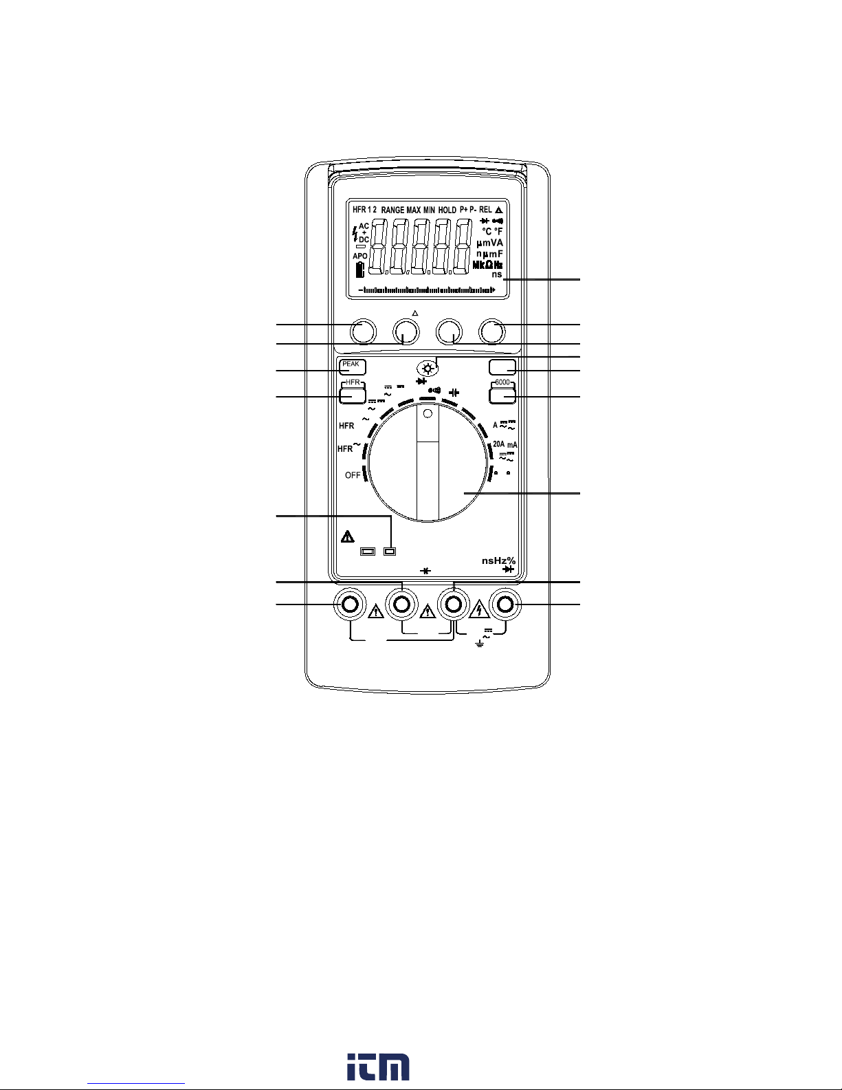
1.3 Front Panel Overview
Figure 1 - Front Panel View
16
11
10
9
8
7
6
2
1
(6000 or RS232)
15
14
13
12
5
4
3
cal>2s
±
+
+
ns
mV
+
V
+
mV
MAX 400mA
TRUE RMS AC+DC
Digital Multimeter
30V
MAX
%
AUTO POWER OFF
CAT.III
V
Ω
Hz %
µ
SHIFT
C
F
K-Type
+
CATIV 600V
0
10 20
50
30
40
60
HOLD
MIN/MAX
RANGE
REL
COM
mAµA20A
20A/30sec
FUSED
MAX
FUSED
Ω
V
750V
MAX
1000V
CATIII 1000V
www. .com
information@itm.com1.800.561.8187
Page 10

11
Front Panel Description
VΩHz%ns
The positive input terminal for
Voltage, Ohms, Frequency, Duty
Cycle, Conductance, Diode
measurements. Connection is made
using the red test lead.
COM
The negative (ground) input terminal
for all measurement modes.
Connection is made to it using the
black test lead.
20A
The positive input terminal for up to
20 A current measurement.
μAmA
The positive input terminal for μA, up
to 400 mA, and capacitive
measurements.
K-Type
The thermocouple input terminal for
temperature measurements.
Function/Range
Rotary Switch
Selects the function and desired
range.
6000/RS232
392 models, this switches between
6000 and 60000 counts. 393 models
this enables computer interface.
Shift
Cycles through the available
secondary options of each function
indicator.
Backlight
Press to activate LCD backlight for
approximately 3 minutes.
MAX/MIN
“MAX” displays the maximum value
measured. “MIN” displays the
minimum value measured. Pressing
button for more than 2 seconds exits
this mode.
HOLD
Displays the current value on the
display even if the leads are removed
from device under test. Pressing the
button again returns to current
reading measurement mode.
HFR
Toggles between “HFR1” (High
Frequency Rejection > 1kHz and
“HFR2” (High Frequency Rejection >
100kHz) on AC voltage ranges.
1
2
3
4 5 6
7
8
12 9 10
11
www. .com
information@itm.com1.800.561.8187
Page 11

12
PEAK+ Cal>2S
Records the peak+ and peak- values
of a measurement with a response
time as low as 1ms. Pressing the
button for more than 2 seconds will
exit the mode.
REL Δ
Pressing the REL button enters the
Relative mode where the meter will
use the displayed value at the time of
the button press an offset value and
that value will be subtracted from the
display of future measurements.
While taking measurements in REL
mode you can press the REL button
again to show the measured value
without the REL offset value. Pressing
the REL button for more than 2
seconds exits the mode.
RANGE
Press the Range button to select the
Manual Range mode. The meter
remains in the range it was in when
the button is pressed. Each press of
the RANGE button will cycle through
the available ranges. Pressing the
button for more than 2 seconds will
exit the Manual Range mode and will
go back to the Auto Range mode.
Display
Displays the measured values,
selected function mode, and
annunciators.
13
14
15
16
www. .com
information@itm.com1.800.561.8187
Page 12

13
2 Getting Started
2.1 Using the Digital Multimeter
With no signal present, set the rotary switch to the desired
measurement function. Ensure proper insertion of the test
leads so they correspond with the type of measurement you
wish to perform, see the following instructions to understand
the proper lead configuration for each measurement type.
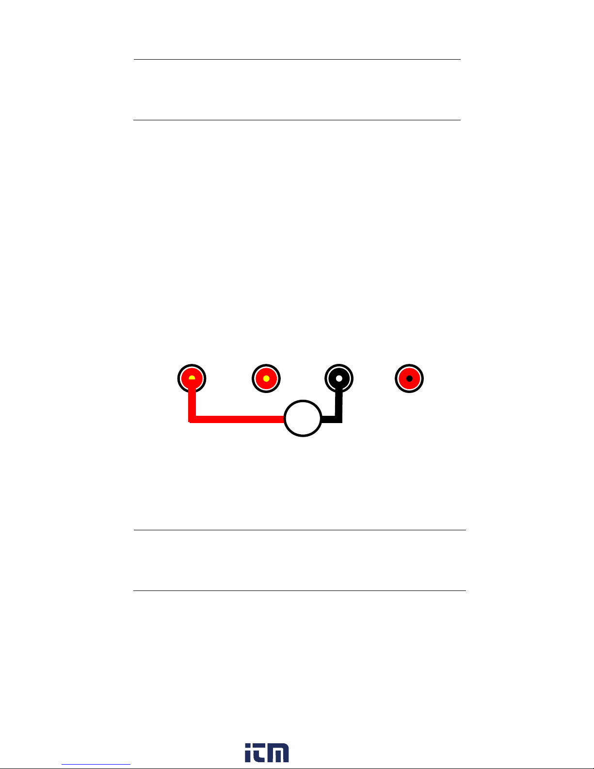
2.2 DC and AC Voltage Measurements
Turn the rotary switch to the corresponding symbol for the
measurement you would like to perform.
Follow these steps to make a measurement.
1. Connect the negative (-) side with the black test lead to
the COM input.
2. Connect the positive (+) side with the red test lead to
the VΩHz%ns input.
3. Probe with the test leads to the DUT and take the
measured reading on display.
Figure 2 - Connection for AC or DC Voltage Measurement
WARNING:
Never connect more than 750 V AC or 1000 V DC
across the input terminals.
uAmA
COM
V.Ω
www. .com
information@itm.com1.800.561.8187
Page 13

14
2.3 DC and AC Current Measurements
Turn the rotary switch to the corresponding symbol for the
measurement you would like to perform.
Current measurements can be made in low current or high
current mode. In low current measurement mode, you can
measure up to 400 mA. Connect to the low current mA terminal
and select one of the two ranges. In high current measurement
mode, you can measure up to 20 A by selecting one of the two
ranges and connecting to the 20 A input terminal.
DC Current ranges: 600 uA (low), 6000 uA (low), 60 mA (low),
400 mA (low), and 20 A (high).
CAUTION:
Always connect the test leads to the instrument
inputs first before connecting the DUT to avoid
potential shock hazard.
Low Current Measurements (< 400 mA)
Follow these steps to make measurements < 400 mA.
1. Connect the negative (-) side with the black test lead to
the COM input.
2. Connect the positive (+) side with the red test lead to
the mA input.
3. Probe with the test leads to the DUT and take the
measured reading on display.
Figure 3 - Connection for Low AC or DC Current Measurement
+
-
www. .com
information@itm.com1.800.561.8187
Page 14
15
WARNING:
Do not connect more than 400 mA DC current
across the mA input terminal or the protection
fuse will be tripped.
Higher Current Measurements (Up to 20 A)
Follow these steps to make measurements up to 20 A.
1. Connect the negative (-) side with the black test lead to
the COM input.
2. Connect the positive (+) side with the red test lead to
the 20 A input.
3. Probe with the test leads to the DUT and take the
measured reading on display.
4. If measuring more than 10 A, keep measurement time
shorter than 30 seconds followed by a 10 minute cool
down period.
Figure 4 - Connection for Higher AC or DC Current
Measurement
WARNING:
Do not connect more than 20 A DC current across
the 20 A input terminal or the protection fuse will
be tripped.
20 A
uAmA
+
-
www. .com
information@itm.com1.800.561.8187
Page 15

16
2.4 Make Resistance Measurements
Turn the rotary switch to the corresponding symbol for the
measurement you would like to perform.
CAUTION:
Always connect the test leads to the instrument
inputs first before connecting the DUT to avoid
potential shock hazard.
Follow these steps to make a measurement.
1. Connect the black test lead to the COM input. Note
that the measurement voltage polarity is positive on
COM input.
2. Connect the red test lead to the VΩHz%ns input.
3. Probe with the test leads to the DUT and take the
measured reading on display.
Figure 2 - Connection for Resistance Measurement
WARNING:
Do not apply more than 1000 V DC across the
terminals or they will be damaged.
uAmA
www. .com
information@itm.com1.800.561.8187
Page 16

17
2.5 Make Diode Measurements
Turn the rotary switch to the corresponding symbol for the
measurement you would like to perform. Press the shift button
to cycle to the diode function.
CAUTION:
Always connect the test leads to the instrument
inputs first before connecting the DUT to avoid
potential shock hazard.
Follow these steps to make a measurement.
1. Connect the black test lead to the COM input.
2. Connect the red test lead to the VΩHz%ns input.
3. Probe with the test leads to the DUT and take the
measured reading on display.
Figure 3 - Connection for Diode Measurement
WARNING:
Do not apply more than 1000 V DC across the
terminals or they will be damaged.
2.6 Continuity Test
Turn the rotary switch to the corresponding symbol for the
measurement you would like to perform. Press the shift button
to display the continuity icon .
uAmA
V.Ω
Diode
www. .com
information@itm.com1.800.561.8187
Page 17

18
Follow these steps for continuity testing:
1. Connect the black test lead to the COM input.
2. Connect the red test lead to the VΩHz%ns input.
3. Connect the two leads together to verify that the
continuity function is working properly. The
instrument should have a continuous beep sound.
4. Probe with the test leads to the DUT and take the
measured reading on display.
5. If continuity is good, it will have a continuous beep
sound.
Figure 4 - Connection for Continuity Test
WARNING:
Do not apply more than 1000 V DC across the
terminals or they will be damaged.
2.7 Make Capacitance Measurements
Turn the rotary switch to the corresponding symbol for the
measurement you would like to perform.
WARNING:
Fully discharge the capacitor before connecting it
to any of the inputs or it may damage the
instrument.
uAmA
COM
V.Ω
www. .com
information@itm.com1.800.561.8187
Page 18

19
CAUTION:
Always connect the test leads to the instrument
inputs first before connecting the DUT to avoid
potential shock hazard.
Follow these steps to make a capacitance measurement.
1. Connect the black test lead to the COM input. This will
connect to the negative side of your capacitor.
2. Connect the red test lead to the uAmA input. This
will connect to the positive side of your capacitor.
3. Probe with the test leads to the DUT and take the
measured reading on display.
4. When the capacitor to be tested is connected, if
“dIS.C” symbol is indicated on the LCD, it means there
is voltage present in the capacitor under test and it
needs to be discharged before testing can continue.
Figure 5 - Connection for Capacitance Measurement
WARNING:
Do not apply more than 1000 V DC across the
terminals or they will be damaged.
2.8 Make Temperature
Measurements
Turn the rotary switch to the corresponding symbol for the
measurement you would like to perform. Press the shift button
to switch between C and F.
uAmA
Capacitor
www. .com
information@itm.com1.800.561.8187
Page 19

20
Follow these steps to make a temperature measurement.
1. Plug the K-type thermocouple directly into the meter.
2. Apply the thermocouple bead tip to the sample you
would like to measure the temperature of.
3. Take measured reading from the display.
2.9 Make Frequency Measurements
Turn the rotary switch to the corresponding symbol for the
measurement you would like to perform.
Follow these steps to make a temperature measurement.
1. Connect the black test lead to the COM input.
2. Connect the red test lead to the VΩHz%ns input.
3. Probe with the test leads to the DUT and take the
measured reading on display.
2.10 Percent Duty Cycle Measurements
Turn the rotary switch to the corresponding symbol for the
measurement you would like to perform. Press the shift button
to switch between Hz and %.
1. Connect the black test lead to the COM input.
2. Connect the red test lead to the VΩHz%ns input.
3. Probe with the test leads to the DUT and take the
measured reading on display.
20 A
uAmA
Frequency
www. .com
information@itm.com1.800.561.8187
Page 20

21
2.11 Auto Power Off
Auto power off occurs approximately after 30 minutes when
there has been no interaction with the meters knobs or
buttons. If an auto power off event occurs, change the position
of the rotary knob to turn the meter back on again. To disable
the auto power off feature, press and hold the MAX/MIN
button while rotating the rotary switch from off to any position.
When the auto power off feature is disabled, the LCD will no
longer display the APO annunciator on the left side of the
display.
3 PC Communication
The 393 digital multimeter comes with application software,
which provides most of the controls that emulate the front
panel of the instrument.
The software is included on the supplied CD or can be
downloaded
Remote communication is supported using the software only.
Remote commands are not available.
20 A
uAmA
COM
V.Ω
% Duty Cycle
www. .com
information@itm.com1.800.561.8187
Page 21

22
4 Specifications
Display: 60000 counts, 60 segments analog bar graph
Polarity: Automatic, (-) negative polarity indication
Overrange Indication: (OL) or (-OL) is displayed
Low Battery Indication: Indicates current capacity of battery.
When BATTERY is fully depleted, the display will show " bAtt "
with a continuous beep sound. The meter then shuts down in
5 seconds and no further measurement is allowed.
Measurement Rate: 2 measurements/sec nominal, 20
measurements/sec for analog bar graph
Operating Environment: 0°C to 50°C at < 70% R.H
Storage Environment: -20°C to 60°C at < 80% R.H
Temperature Coefficient: 0.1 × (specified accuracy) Per °C.
(0°C to 18°C, 28°C or 50°C)
Auto Power Off: Approx. 30 minutes
Altitude: 6561.7 ft (2000 m)
Power: single 9V battery
Battery Life: 50 hours typical with alkaline
Size (H × W × D): 7.8 × 3.6 × 1.7 inches (198 × 90 × 44 mm)
Weight: Approx. 14.1 oz. / 400 grams (including battery)
Accuracy is given as ± (% of reading + number of least
significant digits) at 18°C to 28°C, with relative humidity up to
70%.
Voltage
DC Volts
RANGE
RESOLUTION
Accuracy
Input Impedance
600 mV
0.01 mV
+(0.08% rdg +
5 dgt)
10 MΩ
6 V
0.1 mV
11 MΩ
60 V
1 mV
10 MΩ
600 V
10 mV
10 MΩ
1000 V
100 mV
10 MΩ
Overload protection: 1000 V DC or 750 V AC RMS
www. .com
information@itm.com1.800.561.8187
Page 22

23
AC Volts (True RMS)
Range
Resolution
Accuracy
(45 Hz - 2 kHz) / HFR2
Input
Impedance
600 mV
0.01 mV
+(1.0% rdg + 20 dgt)(1)
+(1.5% rdg + 20 dgt)(2)
10 MΩ
6 V
0.1 mV
11 MΩ
60 V
1 mV
+(1.0% rdg + 20 dgt)(1)
+(1.5% rdg + 20 dgt)(2)
+(2.0% rdg + 20 dgt)(3)
10 MΩ
600 V
10 mV
10 MΩ
750 V
100 mV
+(2.0% rdg + 20 dgt)(4)
10 MΩ
Range
Resolution
Accuracy
(45 - 60 Hz) / HFR1
Input
Impedance
600 mV
0.01 mV
+(2.0% rdg + 20 dgt)
10 MΩ
6 V
0.1 mV
11 MΩ
60 V
1 mV
10 MΩ
600 V
10 mV
10 MΩ
750 V
100 mV
10 MΩ
AC+DC Volts (True RMS)
Range
Resolution
Accuracy (45 Hz - 2 kHz)
Input
Impedance
600 mV
0.01 mV
+(1.5% rdg + 30 dgt)(1)
+(2.0% rdg + 30 dgt)(2)
10 MΩ
6 V
0.1 mV
11 MΩ
60 V
1 mV
+(1.0% rdg + 30 dgt)(1)
+(2.0% rdg + 30 dgt)(2)
+(2.5% rdg + 30 dgt)(3)
10 MΩ
600 V
10 mV
10 MΩ
750 V
100 mV
+(2.5% rdg + 30 dgt)(4)
10 MΩ
(1) For frequency range 45 Hz to 500 Hz.
(2) For frequency range 500 Hz to 1 kHz.
(3) For frequency range 1 kHz to 2 kHz.
(4) For frequency range 45 Hz to 1 kHz.
Crest factor: 3 at full scale and 6 at half scale
AC Coupled True RMS specified from 2% to 100% of range
HFR1 (High Frequency Reject): >1 kHz
HFR2 (High Frequency Reject): >100 kHz
Peak hold accuracy: +(3.0% rdg + 500 dgt) for frequency 45 Hz to
500 Hz at 60 V AC to 750V AC
Overload protection: 1000 V DC or 750 V AC RMS
www. .com
information@itm.com1.800.561.8187
Page 23

24
Current
DC Current
Range
Resolution
Accuracy
600 μA
0.01 μA
+(0.5% rdg +10 dgt)
6000 μA
0.1 μA
60 mA
1 μA
400 mA
10 μA
+(1.0% rdg + 10 dgt)
20 A
1 mA
+(2.0% rdg + 10 dgt)
AC Current (True RMS)
Range
Resolution
Accuracy (45 Hz - 1
kHz)
600 μA
0.01 μA
+(1.5% rdg + 20 dgt)
6000 μA
0.1 μA
60 mA
1 μA
400 mA
10 μA
20 A
1 mA
+(2.5% rdg + 20 dgt)
AC+DC Current (True RMS)
Range
Resolution
Accuracy (45 Hz - 1
kHz)
600 μA
0.01 μA
+(2.0% rdg + 30 dgt)
6000 μA
0.1 μA
60 mA
1 μA
400 mA
10 μA
20 A
1 mA
+(3.0% rdg + 30 dgt)
Burden Voltage:
500 mV on 600 μA & 60 mA ranges
2 V on 6000 μA, 400 mA, 20 A ranges
Input protection:
0.5 A/1000 V fast blow ceramic fuse (6.3x32mm) on μA/mA
input.
20 A/600 V fast blow ceramic fuse (10x38mm) on 20 A input.
20 A Input: >10 A for 30 sec. max, then a 10 min. cooling period.
Crest factor: 3 at full scale and 6 at half scale
AC Coupled True RMS specified from 2% to 100% of range
Peak hold accuracy: +(3.5% rdg + 500 dgt) at 45 Hz to 500 Hz on
AC current ranges
www. .com
information@itm.com1.800.561.8187
Page 24

25
Resistance
Range
Resolution
Accuracy
Open Circuit
Voltage
600 Ω
0.01 Ω
+(0.3% rdg + 20 dgt)
-3.0 V DC typical
6 kΩ
0.1 Ω
+(0.3% rdg + 10 dgt)
-1.2 V DC typical
60 kΩ
1 Ω
+(0.3% rdg + 10 dgt)
-1.2 V DC typical
600 kΩ
10 Ω
+(0.3% rdg + 10 dgt)
-1.2 V DC typical
6 MΩ
100 Ω
+(1.0% rdg + 10 dgt)
-1.2 V DC typical
60 MΩ
1 kΩ
+(3.0% rdg + 20 dgt)
-1.2 V DC typical
Overload protection: 600 V DC or 600 V AC RMS
Continuity Test
Range
Audible
Threshold
Response
Time
Open Circuit
Voltage
600 Ω
<40 Ω
Approximately 100 ms
-3.0 V DC typical
Overload protection: 600 V DC or 600 V AC RMS
Diode Test
Range/
Resolution
Test
Current
Accuracy
Open Circuit
Voltage
2 V / 1 mV
0.5 mA
typical
+(2.0% rdg + 10dgt)
3.0 V DC typical
Audible indication: Less than 0.05 V DC
Overload protection: 600 V DC or 600 V AC RMS
Conductance (6000 counts)
Range
Resolution
Accuracy
Open Circuit
Voltage
60 nS
0.01 nS
+(1.0% rdg + 10 dgt)
-0.7 V DC typical
Equivalent resistance range: 16.7 MΩ to 100 GΩ
(S = Siemens = 1 / Ω )
Overload protection: 600 V DC or 600 V AC RMS
www. .com
information@itm.com1.800.561.8187
Page 25

26
Capacitance (6000 counts)
Range
Resolution
Accuracy
6 nF
0.001 nF
+(3.0% rdg + 30 dgt)
60 nF
0.01 nF
+(3.0% rdg + 10 dgt)
600 nF
0.1 nF
+(3.0% rdg + 10 dgt)
6 μF
0.001 μF
+(3.0% rdg + 10 dgt)
60 μF
0.01 μF
+(3.0% rdg + 10 dgt)
600 μF
0.1 μF
+(3.0% rdg + 10 dgt)
6 mF
1 μF
+(5.0% rdg + 10 dgt)
Overload protection: 600 V DC or 600 V AC RMS
Temperature
Range
Resolution
Accuracy
Sensor Type
-50°C - 0°C
0.1° C
+(2.0% rdg + 3°C)
K-type
Thermocouple
0°C -
400°C
0.1° C
+(1.0% rdg + 1°C)
400°C 1300°C
0.1° C
+(2.0% rdg + 3°C)
-58°F 32°F
0.1° F
+(2.0% rdg + 6°F)
32°F 750°F
0.1° F
+(1.0% rdg + 2°F)
750°F 2372°F
0.1° F
+(2.0% rdg + 6°F)
Overload protection: 30 V DC or 30 V AC RMS
% Duty Cycle
Range
Resolution
Accuracy (5V logic)
Pulse
Width
5% to 95%
0.1%
+(2.0% rdg + 10 dgt)
>10 μs
Frequency range:
5% to 95% (40 Hz to 1 kHz)
10% to 90% (1 kHz to 10 kHz)
20% to 80% (10 kHz to 20 kHz)
Overload protection: 600 V DC or 600 V AC RMS
www. .com
information@itm.com1.800.561.8187
Page 26

27
Frequency
Range
Resolution
Accuracy
Trigger
Level 1
60 Hz
0.001 Hz
+(0.1% rdg + 10 dgt)
>1.5 V
600 Hz
0.01 Hz
>1.5 V
6 kHz
0.1 Hz
>1.5 V
60 kHz
1 Hz
>1.5 V
600 kHz
10 Hz
>1.5 V
6 MHz
100 Hz
>2.5 V,
<5.0 V
10 MHz
1 kHz
>2.5 V,
<5.0 V
Minimum input range: >6 Hz
Minimum pulse width: >100 ns
Duty cycle limits: >30% and <70%
Overload protection: 600 V DC or 600 V AC RMS
www. .com
information@itm.com1.800.561.8187
Page 27

28
10 Maintenance
Do not expose the LCD display to direct sunlight for long periods
of time.
Cleaning
If the instrument requires cleaning, disconnect it from all power
sources and clean only with a mild detergent and water. Be
sure the instrument is completely dry before reconnecting it to
any power source.
To clean the exterior surface:
1. Remove loose dust on the outside of the instrument
and probes with a lint-free cloth.
2. Use a soft cloth dampened with water to clean the
instrument.
Note: To avoid damaging the surface of the instrument and
probes, do not use any chemically abrasive cleaning agents.
BATTERY AND FUSE REPLACEMENT
WARNING
TO AVOID ELECTRICAL SHOCK, DISCONNECT THE TEST LEADS
AND ANY INPUT SIGNALS BEFORE REPLACING THE BATTERY.
REPLACE ONLY WITH SAME TYPE OF BATTERY.
1. Disconnect test leads from any live source, turn the rotary
switch to OFF, and remove the test leads from the input
terminals.
2. The bottom case is secured to the top case by four screws.
Using a Phillips-head screwdriver, remove the screws from the
bottom case and remove the bottom case.
3. Remove battery and replace with a new equivalent " NEDA
1604 " 9-volt battery.
4. Fuse: F1 / 0.5A / 1000V fast blow ceramic fuse (6.3 x 32 mm
size)
5. Fuse: F2 / 20A / 600V fast blow ceramic fuse (10 x 38 mm
size).
6. Replace the bottom case and reinstall the screws.
www. .com
information@itm.com1.800.561.8187
Page 28

29
SERVICE INFORMATION
Warranty Service: Please go the support and service section on our
website
to obtain an RMA #. Return the product
in the original packaging with proof of purchase to the address below.
Clearly state on the RMA the performance problem and return any
leads, probes, connectors and accessories that you are using with the
device.
Non-Warranty Service: Please go the support and service section on
our website
to obtain an RMA #. Return the
product in the original packaging to the address below. Clearly state on
the RMA the performance problem and return any leads, probes,
connectors and accessories that you are using with the device.
Customers not on an open account must include payment in the form
of a money order or credit card. For the most current repair charges
please refer to the service and support section on our website.
Return all merchandise to B&K Precision Corp. with pre-paid shipping.
The flat-rate repair charge for Non-Warranty Service does not include
return shipping. Return shipping to locations in North America is
included for Warranty Service. For overnight shipments and non-North
American shipping fees please contact B&K Precision Corp.
Include with the returned instrument your complete return shipping
address, contact name, phone number and description of problem.
www. .com
information@itm.com1.800.561.8187
Page 29

30
LIMITED THREE-YEAR WARRANTY
B&K Precision Corp. warrants to the original purchaser that its products
and the component parts thereof, will be free from defects in
workmanship and materials for a period of three years from date of
purchase.
B&K Precision Corp. will, without charge, repair or replace, at its
option, defective product or component parts. Returned product must
be accompanied by proof of the purchase date in the form of a sales
receipt.
Exclusions: This warranty does not apply in the event of misuse or
abuse of the product or as a result of unauthorized alterations or
repairs. The warranty is void if the serial number is altered, defaced
or removed.
B&K Precision Corp. shall not be liable for any consequential damages,
including without limitation damages resulting from loss of use. Some
states do not allow limitations of incidental or consequential damages.
So the above limitation or exclusion may not apply to you.
This warranty gives you specific rights and you may have other rights,
which vary from state-to-state.
www. .com
information@itm.com1.800.561.8187
Page 30

© 2013 B&K Precision Corp.
Printed in Taiwan
V120613
www. .com
information@itm.com1.800.561.8187
 Loading...