

Page 1
lnstruction
Manual
Model
2831C 3
llzDigit
Bench Type
Digital
Multimeter
Page 2
TEST
INSTRUMENT
SAFETY
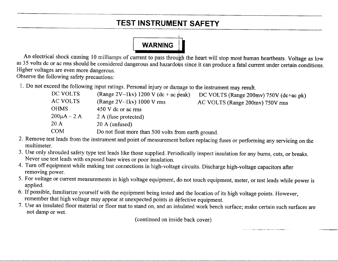
An
electrical
as 35
volts
Higher
voltages
Observe
l. Do
not exceed
2.
Remove
multimeter.
3.
Use
only shrouded
Never
4.
Turn
removing
5. For
voltage
applied.
possible,
6. If
remember
7.
Use an
not
damp
shock
dc
or ac rms
are even
the
following
the following
DC
VOLTS (Range
AC
VOLTS (Range
OHMS
2001tA*2
204
COM
test
leads ffom
use test
offequipment
leads
power.
or current
famlliarize yourself
that high
insulated
floor material
or wet.
causing
should
l0 milliamps
be considered
more
dangerous.
safety precautions:
input
ratings.
450
V dc
A
the
safety
type
with
exposed
while
making
measwements
voltage
(fuse
2 A
(untused)
20 A
Do
not float
instrument
test leads
bare wires
test
in
with
the equipment
may
appear
or floor
WARNING
of current
dangerous
Personal
2v-lkv)
2V-lkv)
or ac nns
protected)
more than
point
and
like
those supplied.
or
comections
high voltage
at unexpected points
mat to
stand on,
(continued
pass
to
and
injury
1200 V
(dc +
1000 V rms
500 volts
of measurement
poor
insulation.
in high-voltagg
equipment,
being tested
and an in5ulated
I
throulh
hazardotrs
or
on inside
since
damage
ac
$eak)
from
before
Periodically
circuits.
do not touch
and
the location
in d6fective
back
the
heart will
stop
it can produie
to the instrument
DC
VOLTS
AC
VOLTS
earth
sround.
replacing
inspect
equipment.
work
cover)
fuses
insulation
Discharge
equipment,
of its high
bench surface:
most human
a fatal
cgrrent
may
result.
(Range
(Range
high-voltage
200mv)
200mv)
performing
or
for any
meter, or
voltage
make certain
heartbeats.
gnder
certain
(dc+ac
750V
750V
rms
any
servicing
burns,
cuts,
capacitors
test leads
points.
while
However,
such
Voltage
conditions.
pk)
on the
or breaks.
after
power
surfaces are
as low
is
Page 3

Instruction Manual
for
Model 2831C
Bench Type
3-112
Digit
MULTIMETER
KKPRECilsffEJ
1031
Segovia
Circle, Placentia
CA
92870
Page 4
TABLE
OF CONTENTS
TEST INSTRUMENT
INTRODUCTION.
SPECIFICATIONS.
OPTIONALACCESSORIES...
CONTROLSANDINDICATORS
CONTROLSANDINDICATORS
OPERATINGINSTRUCTIONS..
Preliminary
VoltageMeasurements
SAFETY
. Inside Front
.......I
.......2
.........5
......,.6
........7
........8
........8
Page
Cover
.....8
CurrentMeasurements
ResistanceMeasurements
... ..........9
...
ContinuityTesting
DiodeTesting ...
MI{TNTENANCE. .
huseReplacement
lineVoltageSelection
f,estleads
InstrumentRepairService
WARRANTY
SERVICEINSTRUCTIONS..
LIMITEDONE-YEARWARRANTY....
Page
.......9
....10
....10
......
....11
.......12
.....12
.....12
.....14
.......15
II
Page 5
INTRODUCTION
The B &
digit multimeter
standard
and resistance
diode test
The
selected
pushbuttons.
with automatic
digits
K Precision
functions
and continuity
instrument
from a
The 3-ll2
Model
a highly
is
voltage,
of
measurements.
functions.
to use,
logically
digit
sign and
panel
is easy
of very
minus
28318
versatile
current
[n addition,
LED
instrument
(with
as all functions
laid out and identified
display features
auto-zero
bench-type 3-ll2
offering
A range),
a 20
it also
includes
are
0.43"'
capability.
The unit is
carrying
folded on
be
other
Safety
extensive
B & K Precision
for the Model
and
B & K
information
housed
handle doubles
instrument.
features
overload
usefulness
Precision
on the
in a rugged,
as a sturdy
the instrument
top of
include
protection, including
offers a full
which
28318
of the
instrument.
distributor
latest accessories.
attractive
jacks,
safety
can further expand
or B & K
plastic
tilt stand.
to allow stacking
line of optional
Please contact
The tilt
safety
a high energy
Precision
and the
case,
stand can
your
with
leads, and
test
fuse.
accessories
the capabilities
your
locai
for more
Page 6
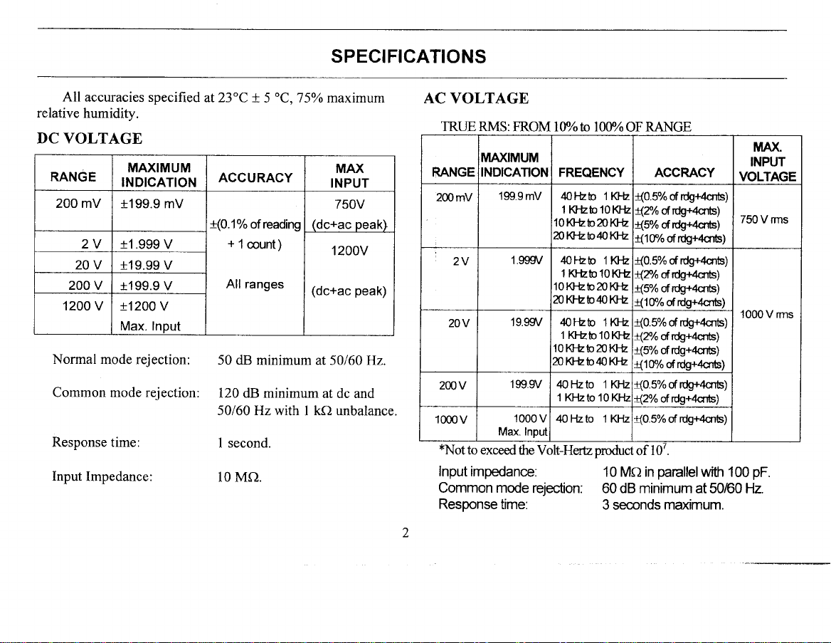
All
accuracies specified
relative
humidity.
DC VOLTAGE
RANGE
200 mV
2V 11.999
20v
200 v
1200 v 11200
Normal
Common mode rejection:
Response time:
Input
MAXIMUM
INDICATION
t199.9 mV
V
+19.99 V
1199.9 V
v
Max. Input
mode rejection:
Impedance:
SPECIFICATIONS
oC,757o
at23"C
+
5
ACCURACY
!(O.1o/o of reading
+
1
count)
All ranges
50 dB
minimum at 50160
120 dB minimum
50160 Hz with I kO unbalance.
I second.
10 MO.
maximum
MAX
INPUT
750V
(dc+ac peak)
1200v
(dc+ac
peak)
at dc and
Hz.
AC
VOLTAGE
TRIIE RMS:
RANGE
200mV
2V
20v
200v
1000v
*Notto
FROM lE/o tD 10V/o
I/IAXIMUM
INDICATION
'199.9mV
1.gSSV 4or-tsb
't9.99V
199.9/
Max. Inpul
exceed the
Input impedance.
Common mode
Response
time:
FREQENCY
4oFtsb 1Kl-E
1 KFtsb 10Kt-E
10Klkb20Klh
nrcb.b&Ki
1 KFLto
10Kt-tsb20Klb
20K]-tsb40KlE
4oFtsb
1 Khtrtc
10Kl-tsb20KI-L
20 Kl-tsb40KlL
40 Flzto 1 KHz
1 KFlzto
1000
v
A0tLlo 1lG-lz
Volt-Her?uoduct
rejection:
OF
t(0.5% of tdg+46651
t(2% ofrdg+acnbl
t(5% of tdg{'4cnb1
t(1flo ofrdg+46651
(0.5%
1Kt-b
10 KJ-L
(2/o
(5%
(1ry0
l Klh
t(0.5% of rdg+4cnb)
10KFL
{2%
t(5% of tdg+466;
t(ltrlo
t(0.5%
10Kl-lz
t(2% ofrdg+4cnts;
{0.5%
ptoducl
of
10 MCl in
dB minimum
60
3 seconds
RANGE
ACCRACY
of rdg+acnbl
tdgr<q6;
of
oftdg+4cnts)
of rdq+4cnb)
rdg+acnbl
of
rdg+4665;
of
tdg+acnt)
of
rdg+
of
cnb)
parallelwith
at 5060 Hz.
maximum.
MAX
INPUT
VOLTAGE
750
V rms
1000 V rms
pF.
100
Page 7
SPECIFICATIONS
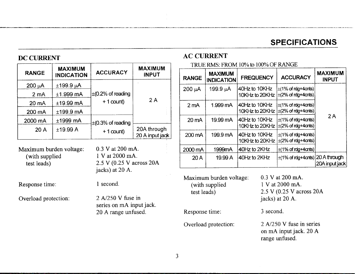
DC CTIRRENT
RANGE
200 uA
2mA t1.999
20 mA
200 mA
2000 mA
204
Maximum burden
(with
leads)
test
Response
Overload
MAXIMUM
INDICATION
1199.9
t19.99 mA
t199.9
t1999
119.99
supplied
time:
protection:
uA
mA
mA
mA
A
voltage:
ACCURACY
of reading
L(0.2%
+
1 count)
of reading
r(0.3%
+
1
count)
V at 200 mA.
0.3
2000 mA.
I V at
(0.25
2.5 Y
jacks)
at
I second.
N250 V
2
on mA
series
range unfused.
20 A
V across
20 A.
fuse in
input
MAXIMUM
INPUT
2A
20A
through
A input
20
20A
jack.
iaqk
AC CURRENT
FROM lUY"
RMS:
TRUE
RANGE
200
2mA
20 mA
200 mA
2000
Maximum
Response
Overload
MAXIMUM
INDICATION
pA
199.9
1.999
19.99
199.9 mA
mA
204
burden
(with
supplied
test leads)
time:
protection:
1999mA
19.99
ta ljV/o OF
FREQUENCY
pA
40Hzto 10KHz
10KHz to
40Hzto 10KHz
mA
1OKFlzto20KHz
mA 40Hzto
lOKHzto 20KHz
40Hzto
1OKHz to
A 4OHzto2KHz
voltage:
1OKHz
10KHz
4OHztoZKHz
RANGE
MAXIMUM
20Ahrough
20KHz
20KHz
ACCURACY
t(1% ofrdg+4cnb'
ofrdg+acnE'
{2%
of tdg+4orb)
{1%
t(2% ofrdg+4cnb)
t(1% oftdg+4cnb;
t(2% ofrdg+acnbl
t(1% ofrdg+qcnS)
rdg+4cr"ts)
of
{2%
(1%
ofrdo+4cntsl
t(1% ofrdg+acnts;
Z0Ainputiac*
V at 200 mA.
0.3
2000 mA.
1 V at
(0-25
2.5 V
jacks)
at 20 A.
3 second.
V
across
20A
2 N250 V fuse in series
jack.
mA input
on
20 A
ranse unfused.
INPUT
2A
Page 8

SPECIFICATIONS
RESISTANCE
MAXIMUM
RANGE
200
20
200 Kc) 199.9 KC)
2000 Kc)
20
NDICATION
o 199.9 c)
2Kl) 1.999
Kf) 19.99
1999 Kc)
MO 19.99
open circuit
Response
time:
KC)
Kc)
Mo t
DIODE TEST
Tested
on 2
Kf) range.
CONTINUITY
Audio tone
typical.
sounds when
(0.2%
1
{0.2%
(0.5%
volage:
ACCUR,ACY
rdq+2cntsl
of
of rdg+1cnt)
of dq+1cnts)
5 V maximum
l0
M e
3 second
20
MO range
I mA test
resistance
TEST
SURRENT
4.2m4
42O
uA
42 uA
4.2
uA
0.42
uA
0.042
uA
loaded
r4ueu wrtl
(
20 seconds
)
current.
is less than
OVERLOAD
PROTECTION
450 V
dc/ac rms
All ranges
with
on
l0 ohms
GENERAL
Temperature
Operating:
Storage:
Humidity range:
Maximum
mode voltage:
Display:
Power
common
requirements:
Dimeensions
weight:
Accessories
SPECIF'ICATIONS
range:
0'C to
-20"C
90%o maximum
80oZ maximum
20
M O range.
+40t
to
500
LED,
100/120/2201240
5W.
([xHxD):
supplied:
261
(10.21
r.63 Kg
Test leads
Instruction
Spare2Atuse(2)
+40t.
+60'C.
to
to
on 2000
70Yo maximum
(non-condensing).
v'
0.43" character
Y, 50160 Hz,
x
7t x 2l
x
(3.6
2.j9
l mm
x
8.3) in
lbs).
(2)
manual
+3511
height.
(l)
. except
k O and
Page 9

OPTIONAL
ACCESSORIES
Model PR-21
Isolatior/Direct
Model TP-30B
Temoerature
Probe
Probe
Model
PR-23
Demodulator
Additional Af
TL-2A
Replacement Test Leads
Probe
I
I
cessories :
Model PR-28A
High-voltage Probe
your
See
B
for more
local
& K Precision
details.
distributor
Page 10
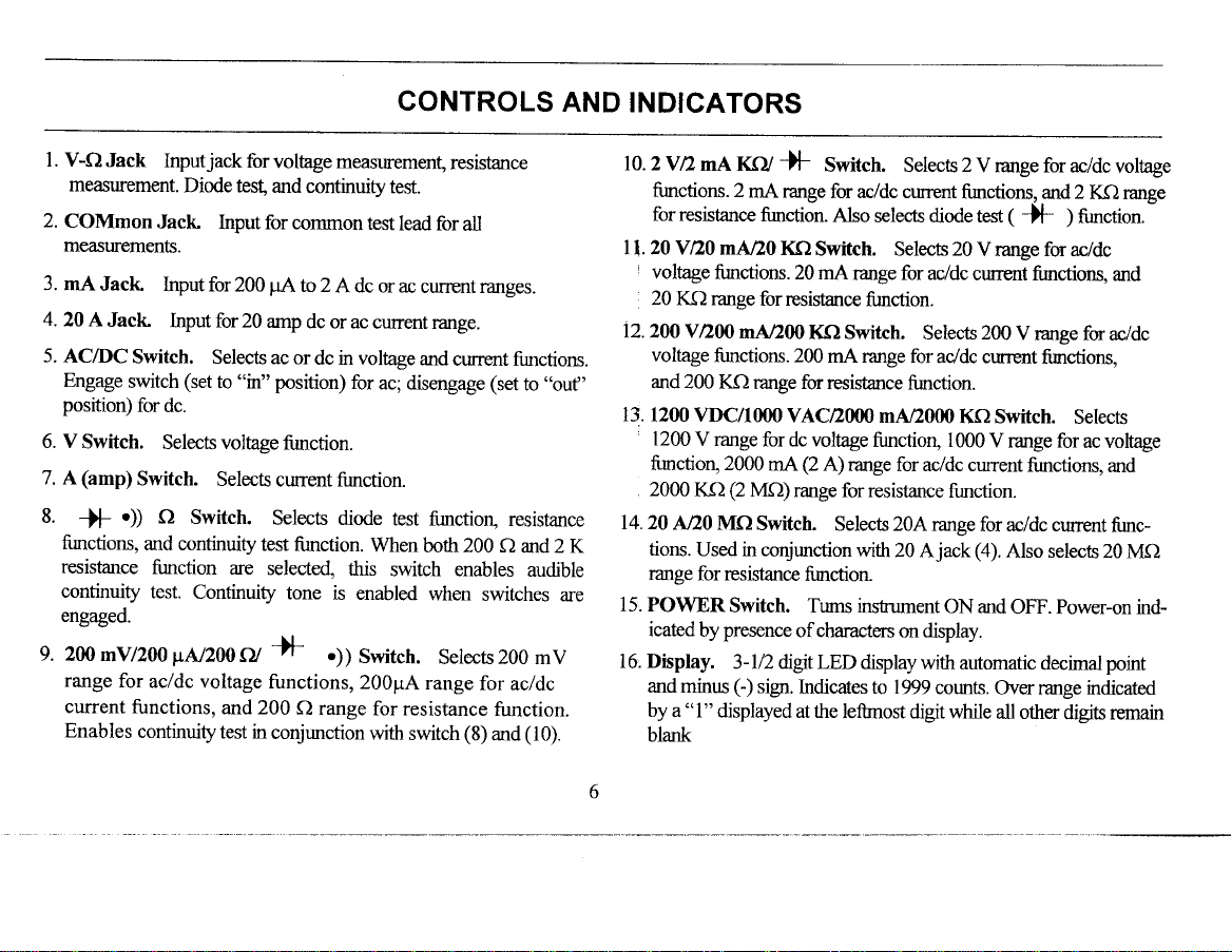
l. V-O
Jack
Inputjack
measurement.
2.
COMmon
measuremeffs.
3. mA
Jack
4.
20
A Jack
5. AC/DC
Engage
position)
6. V
Switch.
(amp)
7. A
8.
)F
firnctions,
resistance
continuity
engaged.
g.
2MmY/200pN200CU
range
for
current
Enables
Diode test
Jaclc
Input for200
Input for
Switch.
(set
switch
for
dc.
Selects voltage
Switch.
O
)
Switch.
and continuity
fi.nction
test.
Continuity
acldc voltage
functions,
continuity
for
volhge measuremen!
and
continuity test.
Input forcommontest
pA
to 2
A dc or ac
20 amp
Selects ac or
"in"
to
Selects
are
and 200
test in
dc or ac
dc in voltage
position)
fi.rnction.
current firnction.
Selects diode
test
selected,
tone
+f
functions,
conjunction
for
fi.mction.
this
is enabled
r))
C) range
Switch.
200pA
When
with
GONTROLS
resistance
lead for
curent range.
ac;
test
switch enables
for resistance
all
currentranges.
and
current fimctions.
disengage
both 200 O
range
switch
(set
finction, resistance
when
switches
Selecrs200 mV
for
acldc
function.
(8)
and
AND
to',ouf'
and 2 K
audible
are
(10).
INDICATORS
rc.zVnmA
finctions. 2
for resistance
ll . 20 V n0
I
voltage
20
K,f2 range
12.200 VD00
voltage
and
200
13.
1200 VDC/1000
1200
V range
firnctiorl 2000
2000
Kf)
4.20
AnI MQ
tions.
Used in co4junction
range
for resistance
15. POWER
icated
by
16 Display.
and
mimrs
"1"
by
a
blank
finctions. 20 mA
functions.
iF
KCy
mA range
firnction.
mA/20 I(O
for resistance
mAn00
Kf) range forresistance
for dc voltage
mAQ
(2
Mf))
Switch.
Switch. Tums instument
presence
3-ln dlgtLED
sigr.
C)
displayed
Switctr.
for acldc current
Also
Switch. Selects 20
KC) Switch.
200 mA range for
VAC2000
A) range for acldc current
range forresistance
Selects 20A range
frmction
ofcharacters
Indicates to 1999
at the
Selects 2 V range for acldc
selects diode test
range for ac,/dc
function.
Selects 200
addc ctnrent
function.
mA/2000
function, 1000
with
20 Ajack
display.
on
display wifh
counts.
lefonost digit while
fi.urctions, and 2
(
tF
V range for ac,/dc
current fimctions,
V range for
finctions,
KQ Switch.
V range for
fi-rnctions,
function.
for acldc current
(a).
Also selects
ON and
OFF.
automatic
Over range
all other
decimal
voltage
Kf) range
function.
)
and
ac/dc
Selects
ac voltage
and
fi.mc-
20 MC)
Power-on ind-
point
indicated
digits rernain
Page 11

CONTROLS
AND INDICATORS
Y/o/->/"0
Fig. 1. Controls
,7
+t.8"'8.8.
7
B 9
and indicators
Page 12

OPERATING
INSTRUCTIONS
Use of test
operator
all instructions
INSTRUMENT
manual
The TEST
of this
current
Failure
in damage
PRELIMINARY
Plug
and turn
Before
manual
input
to
the
unit into
it
on by depressing
equipment
to electric
INSTRUMENT
adhere
to the
contained
SAFETY
using
lists
limits
to these
instrument.
an ac
shock
which
outlet
mqy expose
hazards.
section
this
instrument.
SAFETY
maximum
must
limits
of the
the
POWER
Observe
in
the TEST
of this
section
voltage
be observed.
may result
appropriate
switch.
the
and
voltage
VOLTAGE
l. Press the
2. Select
for
")
position.
3. If the voltage
1200 VDC/I000
4.lf
an approximate
switch
using
being
5. Connect
lead to
6. Connect
measured.
7. Read
MEASUREMENTS
V
function
ac or
dc nreasurement
Push
for the
the range
measured.
the
the COM
the test
the measured
switch.
dc measurement
by setting
"in"
switch
to
be measured
VAC range.
voltage range
range
closest
red test
jack.
desired.
lead to the
leads across
value
Greatest resolution
to
an over range
from the
using
the AC/DC
switch
to disengaged
for ac measurement.
is
unknown,
is known,
jack
V-O
the
circuit
display.
switch.
start with
simply
for the
and the
noints to be
is
black
Set
("out
the
press
attained
voltage
test
the
Page 13

OPERATING
INSTRUCTIONS
CURRENT
1. Press the A function
2.
Select
measurement
dc
switch
3. If the current
the 20 A range,
in
might exceed
MEASUREMENTS
For current meqsurements,
be connected
incorrectly connected
load),
impedance
the
under test.
protection and moy severely
meter or equipment
personal
For
high curent test leads
current measurements
leads
nol only
meqsurement,
the operator.
ac or
"in"
the meter
(almost
or damage
fuse
injury.
current meesurements
could cause
affects the
dc measurement
by setting
for ac measurement.
to be measured
using the
2 A, use high
in series
presents
a short),
the meter
The 20 A
the leads to
could
but
switch.
switch to
20 A
current test leads.
the meter must
wilh the load.
(in
parallel
a very low
which may blow
or equipment
range has on
damage the
test or cause
under
greater thun 2 A,
should be
with standard
accuracy of the
result in injury to
using the
is unknown.
used. High
heat up. This
AC/DC switch. Set
"out"
start with the meter
jack.
If the
If
the
with
fuse
test
position. Push
expected current
4.lf m approximate
switch
the range
current measurements
a. For
lead to the 2 A
b. For curent
current test
cuftent test
Remove
5.
normal circuit
Connect the
6. Apply
porver to the circuit and
display.
RESISTANCE
L Remove
2. Press the
3. Connect
lead to
4. Connect
for
and observe
5. If the
lowest range.
selecting
ceases. At this range,
s
current range is known, simply
for the range desired. Greatest
closest to an
measurements
lead to the COM
power from the circuit rurder measurement and open
metsr in serles with the circuit.
power
fJ function switch.
the red test lead to the V
the COM
the test leads to the desired
expected resistance
higher ranges until the overrange indication
overange for the current being measured.
of 2 A or less, connect the
jack
and the black test lead to the COM
greater
lead to the
path
EASU REMENTS
M
from the equipment under
the reading on the display.
If
20
where the measurement is to be
jack.
The
range is unknown, start with the
overrange is indicated, continue
an
greatest
resolution is attained using
2 A,
than
Ajack and connect
jack.
read
the
red lead is
resolution is achieved.
connect
measured value on the
test.
-O
jack
(+)
polarity.
point
of measurement
press
red
ared high
ablack high
and black test
the
test
jack.
the
taken.
Page 14

OPERATING INSTRUCTIONS
CONTINUITY
l. Remove
2. Press the O switch.
3. Select both 200 Q
200
and 2 K switches
4.
Connect
lead to the
5. Connect the test
the resistance
6. If
(tlpical),
Disengaging
7.
switch at
The instrument
mode.
TESTING
power
from
the red
test lead to the V
jack.
COM
leads to the desired measruement
between the
the
continuity tone will
one of the
"out"
position)
will then
the
equipment under test.
and 2 KC) resistance ranges
simultaneously).
-Ojack
The red lead is
points
two
sound.
two switches
will
disable the
be operating
and the black test
(+) polarity.
is
than 10
less
(200
O and 2 KC)
continuity tone.
in standard ohms
(press
points.
both
ohms
DIODE TESTING
Press the Q
1.
2.
Press
3. Connect the red test lead to the V
lead to the COM
uses conventional-current lead
current flow assumed
4. To check diode forward voltage
the
anode and the black test lead
semiconductor
be checked.
5. The display indicates diode forward
voltages are approximately 0.3
V for silicon devices, and 1.6 V for light emitting diode
An
overrange
near 0 V.
To check
6.
connections to the device. The reading should be
open test leads
leakydiode.
the 2
the
switch.
K switch.
jack.
from
junctions
indicates
reverse-bias
(an
overrange). A lower reading indicates a
-fi
jack
and the black test
(+)
polarity.
The red lead
positive-to-negative).
normal V, of less than 2.0 V can
with
an open
condition
is
polarity
(Vr),
for diode testing
connect the red test lead to
to the cathode. Diodes and
voltage. Normal diode
germanium
V for
diode. A shorted diode reads
ofa diode, reverse the test lead
the
The
meter
(i.e.
diodes, 0.6
(LED's).
as with
same
l0
Page 15

MAINTENANCE
The
qualified
electrical
other
ctions
Remember
line
ument is
turned
perforning
FUSE
range and
to
current
REPLACEMENT
There
operate
fuses.
following
than contained
unless
voltage
off.
two fuses
are
one
(digits
instructions
service
shock,
you
that ac line
input
plugged into an ac
Always
servicing
for the main
lit) but fails
personnel
de not
are
circuits
perform servicing
in the operating
qualified
voltage
any time
unplug the
procedures.
unit - one
in the
power
to measure
are
only.
outlet, even
supply.
use by
for
To avoid
instru-
to do so.
present
is
the instr-
unit before
If
current,
on
if
for the mA
your
unit continpes
check
l
I
!
.
current
the two
Gurrent Range
Note: The
changed
the unit. Simply
terminal counterclockwise.
Then remove
blown,
blow firse
fineholder.
without
replace
Power Supply
your
If
fi4e
supply
some defect
investigation of the
A, 250 V,
0.25
100/120V
I
96-300-0-
Fuse
fuse most
the entire assembly,
it with the appropriate
@art
likely
removal. It is
case
use a flat
number
Fuse
does not
unit
(See
occurs
operatiorl
for 220/240
I 2 5\
operate at all
2) . Note: This
Fig.
the instrument,
in
for its opening.
reason
fast-blow
125 mA, 250 V,
or
V operation.
to open first
blade screwdriver
including
196-300-2-000).
number
Sart
can be inspected
located on
the
2
A,250
(no
digits
fuse should
Replace
Use the appropriate
fast-blow
the rear
fuse. If this
V, 5
Then replace
lit), check
196-300-0-250)
panel
rotate the
to
fLse is
x
20 mm
power
not open unless
it
(part
only
number
after
value:
and
of
fast-
the
for
ll
Page 16

MAINTENANCE
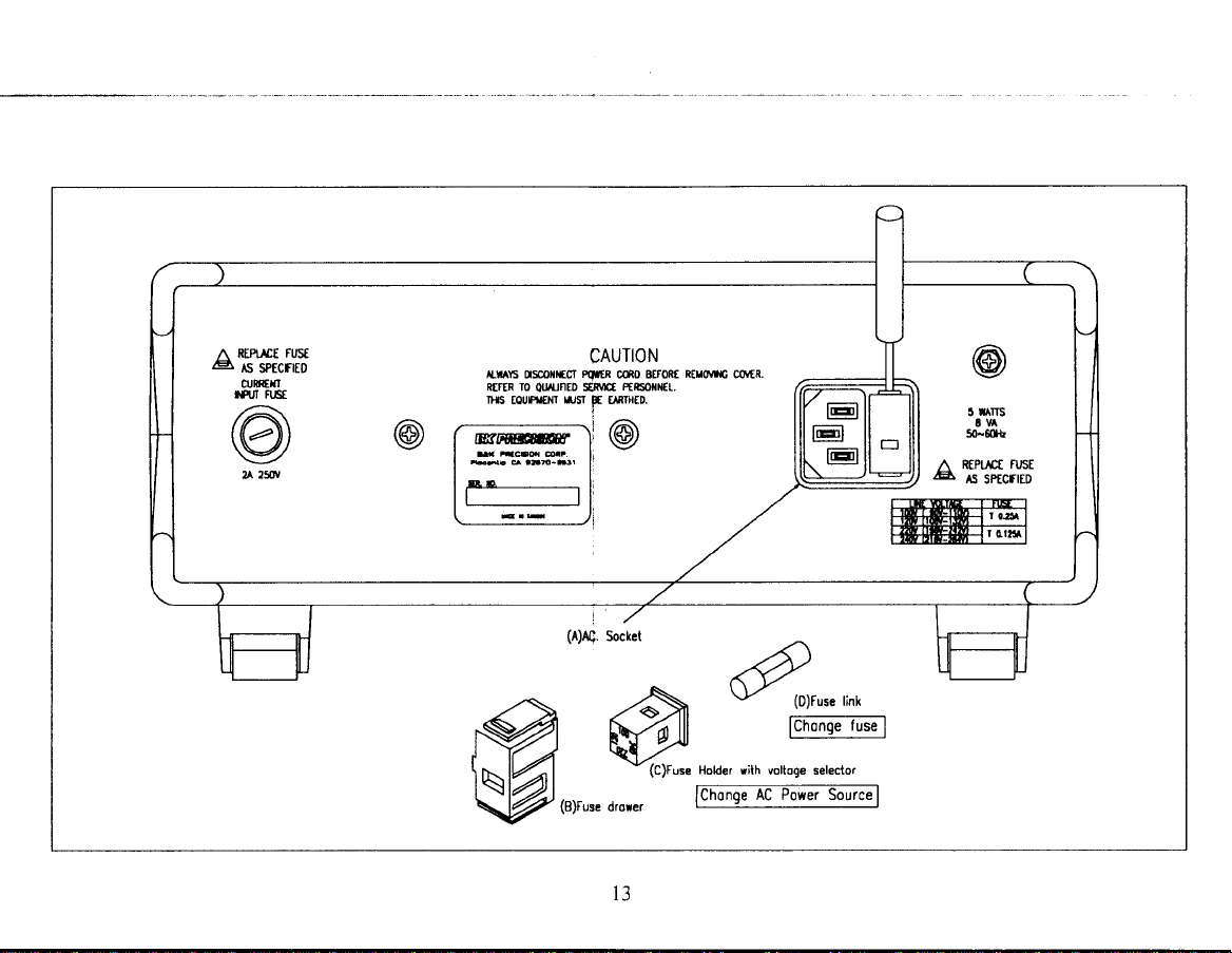
LINE V9LTAGE
This instrument
220y
and240v.
charge fuse.
l. Extract
of a
screwdrive
extracted
2. Pull
rating in accordance
3.
Plugging fuse
shown
holder before
indication.
4.
Install the fuse drawer
is the universal
The below
the tuse
with the
out the fuse
holder into
on the fuse drawer
insert
SELEGTI9N
line operation:
is explaining
drawer
(The
from
extra
aid of
from the
with specific
fuse drawer
into
the AC
safe
a flat
blade scre\4
fuse
holder and charge
the
Line voltage
is correct.
AC
100V, 120V,
the user
socket with the aid
fuse drawer can
required'
Rotating
to have
sollect.
how to
' .
'qrlver')
indication
the fuse
correct voltase
only
the
be
fuse
TEST
conductors
good
these
type replacement
INSTRUMENT
for
rely
network
this
longer
WARRANTY
T;;Xl*.tn"re
LEADS
Periodically
are not intermittent
contact
areas
free from
Because
of the specialized
inskument
upon B &
of B
purpose.
under warranty,
examine
pressure
repair and calibration'
& K
To
the test leads
or broken.. Also
exists at
dirt and corrosion.
test leads.
REPAIR SERVICE
k Precision for this
Precision
use this service, even
SERVICE
is a
nominal charge for
the test lead receptacles.
skills and test equipment
authorized
follow the instructions given
INSTRUCTIONS
to ensure that
make
Use shrouded
many customers prefer
service. We maintain
service
if the instrument
agencies for
section of this
instruments out of
the
that
sure
Keep
safeW
required
is no
in
to
a
the
t2
Page 17
ru'trff
n
lB
r'UI FIJST
,/:\
lr i\l
t\,4'I I
\=/
Fust
6 996p159
O,|intfI
2 25(ry
tLi ls oscol|rffi
RtrtR r0
ol{rnD $Fllct
llrs
EouFil€r{r
CAUTION
PilER
LJsT
tr[rHED.
r
(B)Fuse
drorer
cso BEF0RI
Fttsofn€r..
-'A
Mlll
v1c1ru""
l3
Rtuo\,$6
covER
"e
u"
(D)Fuse
rink
Fhln'eiusel
Holder
rilh voltoge selector
Iiio.qe-ncPowersource|
n
GL
RfPuct
FUst
6 5pgggl5p
Page 18

WARRANTY
SERVICE I NSTRUCTIONS
Warranty
state in writing the
Contact B&K Precision to obtain a Return Authorization
appear
Non-Warranty
performance problem
account
before shipping the
B&K. The RA number
Return all merchandise to B&K Precision
locations in North America. For overnight shipments and
B&K
1031
Placentia,
www.bkprecision.com
Service: Please retum the
performance problem
on the address label.
Service: Return
and return any leads, connectors
include
must
Precision
Segovia Circle Facsimile: 714-237-9214
C492870 Email: service@bkprecision.com
payment
product.
Corp.
in the form of a money
Contact B&K Precision to
must appear
Include with the instrument
description
problem.
of
product
the product
on the address label.
your
in the
original
and retum any leads, comectors and
in the original
and accessoribs that
order or credit card. For the most current repair charges
Corp. with
Phone: 714-237-9220
pre-paid
complete return shipping address, contact name,
packaging
number before shipping the
packaging
obtain a Rdturn Authorization number before shipping
shipping. The flat-rate repair charge includes return shipping to
non-North America shipping fees contact B&K Precision Corp..
proof
with
accessories
the
to
you
are using with the device. Customers not on open
purchase
of
product
below address. Clearly state
to the below
you
that
are using with the device.
to B&K. The RA
contact the factory
phone
address. Clearly
number
in writing the
the
number and
product
must
to
l4
Page 19

B&K Precision
defects in workmanship
Corp. warrants
to the original
and materials
LTMITED ONE-YEAR
period of one
for a
purchaser
that its
year
from
WARRANTY
product
the date of
the component
and
purchase.
parts thereof, will
free from
be
B&K Precision Corp.
product
To obtain warranty
to B&K Precision
Exclusions:
alternations
B&K Precision
loss of use.
not apply to
This
must be
warranty
accompanied
coverage
Corp., l03l Segovia
This warranty
or repairs.
Corp. shall not be
Some states do
you.
gives you
will without
in the U.S.A.,
does
It is void if the serial
not allow
specific
charge,
proof
by
of the
Circle,
not apply in the
liable for any consequintial
limitation of incidental
rights and
you
repair or replace, at
purchase
product must be registered
this
Placentia, CA92870
event
number
have other
may
the form a sales
date in
misuse
pf
qlternated,
is
or consequential
rights, which vary
15
its' option, defective
receipt.
by completing
within fifteen
or abuse
defaced
damages, including
(15)
of the
removed.
or
damages,
from
product
and mailing the
days flom
product or as a result of
without limitation
so
state-to-state.
or component
enclosed
proof of
the above limitation
purchase.
damages
parts. Returned
warranty card
unauthorized
resulting
exclusion
or
from
may
Page 20

TEST
INSTRUMENT SAFEW
8. Keep
9. When using a
lO.Some equipment with a two-wire ac
l1.B & K Precision
l2.When testing ac
13.Never work alone. Someone should
"one
hand in the
metal
includes most recent
customer.
the
does this
measurements in
under test. The B & K Precision Model
suitable for most applications. To be on
are sure it has an isolated chassis or an earth
the human body, or
connection from or to our equipment
system whose
or effectiveness.
on-off switch, fuses,
tumed off.
first aid is highly recommended.
object
present
that could
probe,
When
failure to
powered
pocket"
provide
touch only
television receivers
the cabinet is removed for servicipg, a serious shock hazard exists
a dangerous shock
"hot
chassis" equipment, always cofflect an
products
for
use
perform
power
while handing
good ground
a
the insulated
power
hazard,
are not authorized for use
as a critical component in
can be reasonably expected to cause
equipment, remember that aq line voltage is usually
transformer, etc. any time the equipment
be nearby to render
(continued
portion.
cord, including some
and audio
but
TR-l10
the
safe side,
ground
via any cabling op
instrument
an
path.
rehrrn
eqgipment. A
damagg
or l6Q4
chtissis.
from inside
Never touch the exposed tip
peat
front cover)
probe.
with
plastic
test instruments or the equipment under test may result. To make
to
isolation transformer between the ac outlet and the equipment
Isolation Transformer, or Model 1653 or l655AC Power Supply is
all two-wire ac
any application involving direct contact between our
in
ja
life support device or system. Here,
switching
if necessary. Training in CPR
aid
particularly
Be
portion.
polarized power plugs,
or wooden
means. A
failure
is
connected
powered
"critical
ofthat
cabinet
equipment as
device
present
to
careful to avoid contacting a
"hot
is the
insulates the chassis
if
chassis is
the
"direct
component of a life support device or
or system,
on some
an
power input
ac
outlet,
(cardio-pulmonary
chassis" type. This
touched.
"hot
chassis" unless
contact"
or to affect its safety
circuits
even if the equipment is
nearby
protect
to
Not only
product
refers to any
such as
resuscitation)
you
and
Page 21

PAtr: 481-316-9-001
Printed
@ 19998&K
in Taiwan
Precision
Corp.
1031
Segovia
Placentia,
Circle
CA 9287
0-7 137
USA
TEL:714-237-9220
pd,.
F
714-237
www.bkprecision.com
-9214
 Loading...