

Page 1

OPERATING INSTRUCTIONS
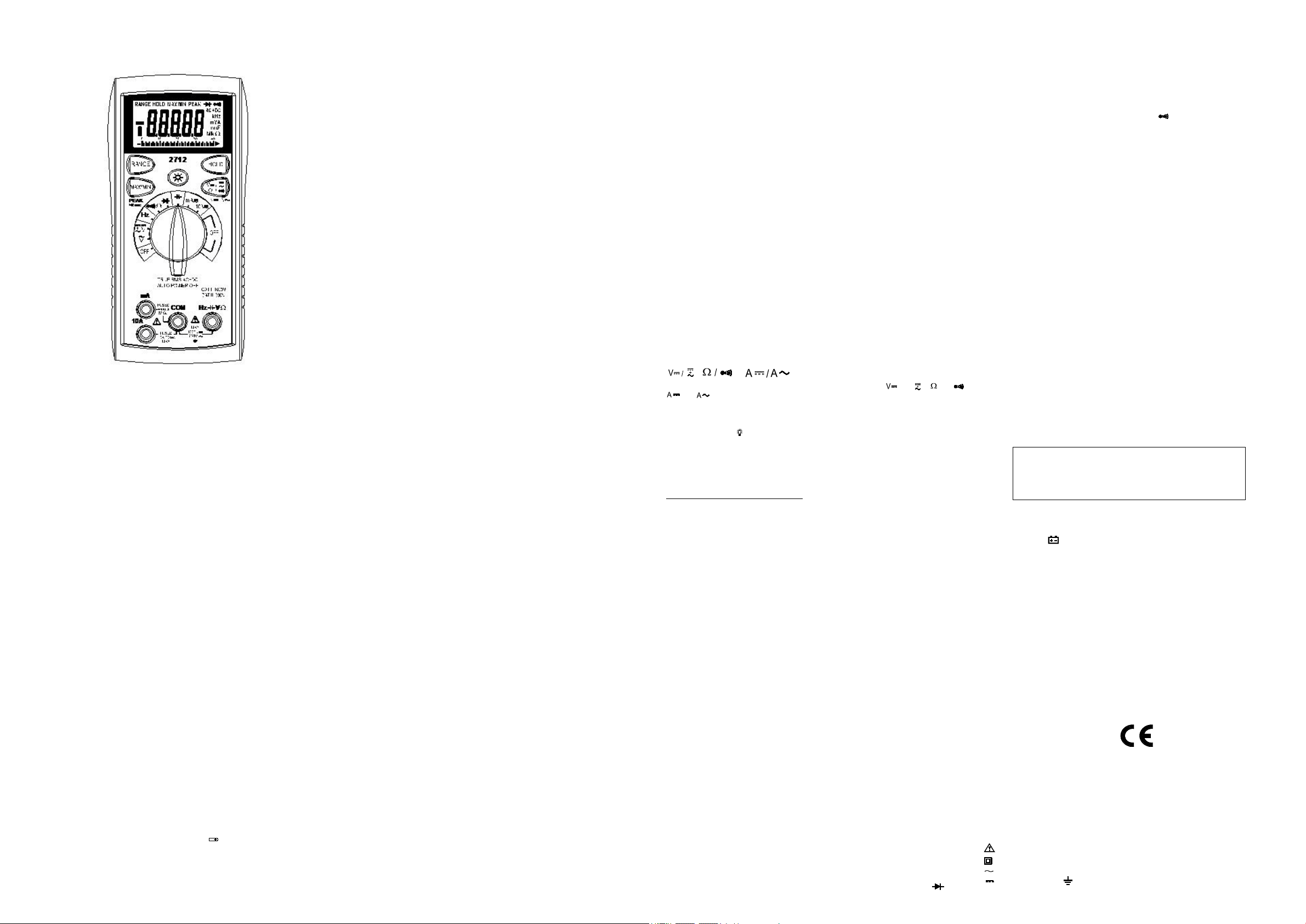
MODEL 2712
DIGITAL MULTIMETER
SAFETY INFORMATION
The following safety information must be observed to ensure maximum personal
safety during the operation at this meter:
Use the meter only as specified in this manual or the protection provided by the
meter might be impaired.
Test the meter on a known voltage before using it to determine if hazardous
voltage is present.
Do not use the meter if the meter or test leads look damaged, or if you suspect
that the meter is not operating properly.
Never ground yourself when taking electrical measurements. Do not touch
exposed metal pipes, outlets, fixtures, etc., which might be at ground potential.
Keep your body isolated from ground by using dry clothing, rubber shoes, rubber
mats, or any approved insulating material.
Turn off power to the circuit under test before cutting, unsoldering, or breaking
the circuit. Small amounts of current can be dangerous.
Use caution when working above 60V dc or 30V ac rms. Such voltages pose a
shock hazard.
When using the probes, keep your fingers behind the finger guards on the
probes.
Measuring voltage which exceeds the limits of the multimeter may damage the
meter and expose the operator to a shock hazard. Always recognize the meter
voltage limits as stated on the front of the meter.
SPECIFICATIONS
Display: 4¾ digit liquid crystal display (LCD) with a maximum reading of 40000.
Analog bargraph: 40 segments with measurements 20 times per second.
Polarity: Automatic, positive implied, negative polarity indication.
Overrange: MSD(Most Significant Digit) blinks .
Zero: Automatic.
Low battery indication: The
displayed when the battery voltage drops
below the operating level.
Measurement rate: 2 times per second, nominal.
Auto power off: Approx. 30 minutes.
Operating environment: 0℃ to 50℃ at < 70% relative humidity.
Storage temperature: -20℃ to 60℃ at < 80% relative humidity.
Accuracy: Stated accuracy at 23℃±5℃, <
is
"
"
75% relative humidity.
Temperature Coefficient: 0.1 x (specified accuracy) per ℃. (℃ to 18℃, 28℃
to 50℃).
Altitude: 6561.7 feet (2000m).
Power: Single standard 9-volt battery, NEDA
1604, JIS 006P, IEC 6F22.
Battery life: 150 hours typical with carbon-zinc.
Dimensions: 165mm (H) x78mm (W) x42.5mm (D).
Weight: Approx. 10.0 oz.(285g) including holster.
Accessories: One pair test leads, one spare
fuse, 9V battery (installed), and Operating
Instructions.
DC VOLTS
Ranges: 400mV, 4V, 40V, 400V, 1000V
Resolution: 0.01mV
Accuracy: ± ( 0.15% rdg + 10 dgts) on 400mV range
± (0.1% rdg + 5 dgts) on 4V to 1000V ranges
Input impedance: 400mV: >3MΩ; 4V ~ 1000V:2.3MΩ
Overload protection: 1000VDC or 750VAC rms
AC VOLTS (TRUE RMS) (45Hz – 1kHz)
Ranges: 400mV, 4V, 40V, 400V, 750V
Resolution: 0.01mV
Accuracy:
± (1.2% rdg + 20dgts) 45 ~ 60Hz on 400mV to 400V ranges
± (1.5% rdg + 20 dgts) 60 ~ 500Hz on 4V range
± (1.5% rdg + 20dgts) 60 ~ 1kHz on 40V to 400V ranges
± (2.0% rdg + 20 dgts) 45 ~ 500Hz on 750V range
AC+DC VOLTS (TRUE RMS) (45Hz - 1kHz)
Ranges: 400mV, 4V, 40V, 400V, 750V
Resolution: 0.01mV
Accuracy:
± (1.5% rdg + 20dgts) 45 ~ 60Hz on 4V to 400V ranges
± (2.0%
rdg + 20 dgts) 60 ~ 500Hz on 4V range
± (2.0% rdg + 20dgts) 60 ~ 1kHz on 40V to 400V ranges
± (2.0% rdg + 20 dgts) 45 ~ 500Hz on 750V range
Crest factor: ≤3
AC coupled true rms specified from 10% to 100% of range.
Input impedance:
Overload protection: 1000VDC or 750VAC rms
400mV: >3MΩ; 4V ~750V:2.3MΩ
CURRENT
Ranges: 40mA, 400mA, 10A
Resolution: 1uA
DC accuracy:
± (0.5% rdg + 10 dgts) on 40mA to 400mA ranges
± (1.5% rdg + 10 dgts) on 10A range
AC accuracy: (TRUE RMS) (50Hz ~ 1kHz)
± (2.0% rdg + 30 dgts) on 40mA to 400mA ranges
± (2.5% rdg + 30 dgts) on 10A range
Crest factor: ≤3
AC coupled true rms specified from 10% to 100% of range.
Voltage burden: 0.2V on 40mA, 10A ranges
Input protection: 0.5A/500V fast blow ceramic fuse
10A/500V fast blow ceramic fuse
10A Input: 10A for 60 seconds maximum followed by a 10 minute cooling period.
1V on 400mA range
RESISTANCE
Ranges: 400Ω, 4kΩ, 40kΩ, 400kΩ, 4MΩ, 40MΩ
Resolution: 0.01Ω
Accuracy:
± (0.3% rdg + 15dgts) on 400Ω range
± (0.3% rdg + 5dgts) on 4kΩ to 400kΩ ranges
± (0.5% rdg +10 dgts) on 4MΩ range
± (1.5% rdg + 20 dgts) on 40MΩ range
Open circuit volts typical: 1.
Over
load protection: 500VDC or AC rms
2Vdc (2.5Vdc on 400Ω range)
CAPACITANCE
Ranges: 4nF, 40nF, 400nF, 4uF, 40uF
Resolution: 1pF
Accuracy: ± ( 3.0% rdg + 20 dgts) on 4nF range
± (3.0% rdg + 5 dgts) on 40nF to 400nF ranges
± (3.0% rdg + 5 dgts) on 4uF to 20uF ranges
± (5.0% rdg + 5 dgts) on 20uF to 40uF ranges
Overload protection: 500VDC or AC rms
FREQUENCY
Ranges: 100Hz, 1kHz, 10kHz, 100kHz, 500kHz
Resolution: 0.01Hz
Accuracy: ± ( 0.1% rdg + 10 dgts)
Sensitivity: 5Hz ~ 100kHz: >500mV rms, 100kHz ~ 500kHz: >1.5V rms
Minimum input range: >5Hz
Minimum pulse width: > 2us
Duty cycle limits: > 30% and < 70%
Ov
erload protection: 500VDC or AC rms
DIODE TEST
Test current: 0.8mA (approximate)
Accuracy: ±(1.5% rdg + 10 dgts)
Open circuit volts: 3.0Vdc typical
Overload protection: 500VDC or AC rms
CONTINUITY
Audible indication: Less than 40Ω
Response time: 500ms
Overload protection: 500VDC or AC rms
fuse on 1.5V range.
OP ER AT IO N
Before taking any measurements, read the Safety Information Section. Always
examine the instrument for damage, contamination (excessive dirt, grease, etc.)
and defects.
Examine the test leads for cracked or frayed insulation. If any abnormal
conditions exist do not attempt to make any measurements.
MAX / MIN/PEAK
The "MAX" displays the maximum value of measurements. The "MIN" displays
the minimum value of measurements. press MAX/MIN/PEAK button for more
than 2 seconds on this button allows to switch PEAK mode. Press
MAX/MIN/PEAK button again to exit the mode.
PEAK mode: It is usable with AC voltage, AC current measurements.
PEAK mode response time: more than 1 ms.
, ,
Use this button to select or , or , or range
position.
Button
HOLD
Press [HOLD] button to toggle in and out of the Data Hold mode.
In the data hold mode, the " HOLD" annun-ciator is displayed and the last
reading is held on the display.
Press [HOLD] button again to release the hold and current readings are once
again displayed.
Backlight
Press the button to activate the backlight for approximately 60 second.
Manually Selecting Range
The meter also has a manual range mode. In manual range, you select and lock
the meter in a range. To manually select a range:
Press [RANGE] button to hold the selected
range. Subsequently pressing the [RANGE] button will select each range in
sequence from the lowest to highest range. Hold the button for 2 seconds to
return to the Autorange Mode.
Voltage Measurements
1.Connect the red test lead to ”VΩ” jack and
the black test lead to the ”COM” jack.
2.Set the Function/Range switch to the desired voltage type (AC or DC) and
range. If magnitude of voltage is not known, set switch to the highest range
and reduce until a satisfactory reading is obtained.
3.Connect the test leads to the device or circuit being measured.
4. For dc, a (-) sign is displayed for negative polarity; positive polarity is implied.
Current Measurements
1.Connect the red test lead to the (mA or 10A) jack and the black test lead to the
"COM" jack.
2.Set the Function/Range switch to the DC or AC ranges.
3.Remove power from the circuit under test and open the normal circuit path
where the measurement is to be taken. Connect the meter in series with the
circuit.
4.Apply power and read the value from the display.
Resistance Measurements
1.Set the Function/Range switch to the desired resistance range.
2.Reove power from the equipment under test.
3.Connect the red test lead to the "VΩ " jack and the black test lead to the "COM"
jack.
4.Connect the test leads to the points of measurements and read the value from
the display.
Diode Tests
1.Connect the red test lead to the “ V Ω” jack and the black test lead to
the ”COM” jack.
2.Set the Function/Range switch to the “
3.Turn off power to the circuit under test. External voltage across the
components causes invalid readings.
4.Touch probes to the diode. A forward-voltage drop is about 0.6V (typical for a
silicon diode).
5.Reverse probes. If the diode is good, “MSD blinks”
displayed. If the diode is shorted, “000” or another number is displayed.
6. If the diode is open, “MSD blinks”.
“ position.
Continuity Measurements
1.Set the Function switch to the position.
2.Turn off power to the circuit under test. External Voltage across the
components causes invalid reading.
3.Connect the test leads to the two points at which continuity is to be tested. The
buzzer will sound if the resistance is less than approximately 40Ω.
Capacitance M easurements
1.Set the Function/Range switch to the desired capacitance range.
2.Connect the red test lead to the “VΩ” jack and the black test lead to the “COM”
jack.
3. Touch the probes to the capacitor. Observe polarity when measuring polarized
capacitors.
4.Read the capacitance directly from the display.
5. Discharge the capacitor before taking capacitance measurements.
Frequency M easurements
1.Set the Function/Range switch to the ”Hz” position.
2. Use this button to select “Hz “ range position.
3.Connect the red test lead to the “VΩ” jack and the black test lead to the
“COM” jack.
4.Connect the test leads to the point of measurement and read the frequency
from the display.
Auto Power Off
1. Auto power off: approx. 30 minutes.
2. After auto power off, move the function switch to OFF position to re-start the
meter.
MAINTENANCE
Remove test leads before changing battery or fuse or
WARNING
performing any servicing.
Battery Replacement
Power is supplied by a 9 volt battery. (NEDA 1604, IEC 6F22). The
on the LCD display when replacement is needed. To replace the battery, remove
the three screws from the back of the meter and lift off the front case. Remove
the battery from case bottom.
"
appears
"
Fuse Replacement
If no current measurements are possible. Check for a blown overload protection
fuse. For access to fuses, remove the three screws from the back of the meter
and lift off the front case. Replace F1 only with the original type 0.5A/500V, fast
acting ceramic fuse, 6.35x32mm Replace F2 only with the original type
10A/600V, fast acting ceramic fuse, 6.35x25.4mm.
Cleaning
Wipe the case with a damp cloth and mild detergent. Do not use abrasives or
solvents. Dirt or moisture in the terminals can affect readings.
Safety: Conforms to IEC61010-1 (EN61010-1), CATII 1000V, CATIII 600V, Class
II, Pollution degree 2 Indoor use.
CATII: Is for measurements performed on circuits directly connected to the
low-voltage installation.
CAT III: Is for measurements performed in the building installation.
EMC: Conforms to EN61326.
The symbols used on this instrument are:
Caution, refer to accompanying documents
Equipment protected throughout by Double insulation (Class II)
Alternating current
Direct current
Ground
Page 2
INSTRUCCIONES DE OPERACION
MULTIMETRO DIGITAL
MODELO 2712
INFORMACION DE SEGURIDAD
La siguiente información es de mucha importancia y debe ser observada para
asegurar una máxima seguridad personal durante la operación de este medidor.
Use el medidor solamente como sea especificado en este manual o la
protección indicada por el medidor podría ser inválida.
Pruebe el medidor utilizando un voltaje determinado conocido antes de utilizarlo
para determinar si el voltaje presente es peligroso.
No utilice el medidor si el mismo o las puntas de prueba parecen estar dañadas,
o si sospecha que el medidor no está operando correctamente.
Nunca "haga tierra física " usted mismo al tomar medidas eléctricas. No tocar
pipas de metal, salidas o llaves, etc. que estén expuestas, pues podrían ser un
potencial de "tierra". Mantenga su cuerpo aislado "de tierras físicas" utilizando
ropa seca, zapatos de goma, alfombra de goma, o cualquier material de
aislación que esté aprobado.
Apague por completo la alimentación del circuito que está en prueba antes de
cortar, desoldar, o abrir el circuito. Recuerde que hasta pequeñas cantidad de
corriente pueden ser peligrosas.
Use extrema precaución cuando trabaje sobre los 60V DC o 30V AC rms.
Voltajes como estos poseen un “peligro de shock”.
Cuando utilice las puntas de prueba, mantenga sus dedos detrás de las
protecciones que fueron diseñadas para colocar los dedos de las puntas de
prueba.
Medir voltaje que excede los límites del multímetro podría resultar en daños al
medidor y exponer al operador a un “peligro de shock”. Siempre verifique los
límites de voltaje del medidor tal como esté especificado en el frente del
medidor.
ESPECIFICACIONES
Pantalla: Pantalla líquida de cristal (LCD) de 4¾ dígitos con una lectura máxima
de 40000.
Gráfico de Barra Análoga: 40 segmentos con medidas de 20 veces por
segundo.
Polaridad: Automática, positiva implicada, indicación de polaridad negativa
Sobre Rango: El MSD estará intermitente. (MSD: Most Significant Digit o los
Dígitos más significantes)
Cero: Automático.
Indicador de Baja Batería: Muestra el signo
batería está por debajo del nivel operacional.
Rango de Medida: 2 veces por segundo, nominal.
Auto Apagado: aproximadamente a los 30 minutos.
Medio Ambiente de Operación: 0℃ a 50℃, a < 70% de humedad relativa.
Temperatura de Almacenaje: -20℃ a 60℃ a < 80% de humedad relativa.
cuando el voltaje de
"
"
Exactitud: Muestra exactitud a 23℃± 5℃, < 75% de humedad relativa.
Coeficiente de Temperatura: 0.1 x (exactitud especificada) por ℃. (℃ a
18℃, 28℃ a 50℃).
Altitud: 6561.7 pies (2000m).
Alimentación: Batería estándar de 9-voltios, NEDA 1604, JIS 006P, IEC 6F22.
Vida de la Batería: 150 horas típicas con carbón-zinc.
Dimensiones: 165mm (H) x78mm (W) x42.5mm (D).
Peso: Aprox . 10.0 onzas. (285g).
Accesorios: Un par de puntas de prueba, un fusible de repuesto, una batería de
9V (instalada), e Instrucciones de Operación.
VO LTAJE DC
Rangos: 400mV , 4V, 40V, 400V, 1000V
Resolución: 0.01mV
Exactitud: ± (0.15% lectura + 10 dígitos) en rangos de 400mV
± (0.1% lectura + 5 dígitos) en rangos de 4V a 1000V
Impedancia de Entrada:
Protección de sobrecarga: 1000VDC o 750VAC rms
400mV: >3MΩ; 4V ~ 1000V:2.3MΩ
VOLTAJE AC (VERDADERO RMS) (45Hz – 1kHz)
Rangos: 400mV, 4V, 40V, 400V, 750V
Resolución: 0.01mV
Exactitud:
± (1.2% lectura + 20 dígitos) 45 ~ 60Hz en rangos de 400mV a 400V
± (1.5% lectura + 20 dígitos) 60 ~ 500Hz en rangos de 4V
± (1.5% lectura + 20 dígitos) 60 ~ 1kHz en rangos de 40V a 400V
± (2.0% lectura + 20 dígitos) 45 ~ 500Hz en rangos de 750V
VOLTAJES AC+DC (45Hz - 1kHz)
Rangos: 4V, 40V, 400V, 750V
Resolución: 0.1mV
Exactitud:
± (1.5% lectura + 20 dígitos) 45 ~ 60Hz en rangos de 4V a 400V
± (2.0% lectura + 20 dígitos) 60 ~ 500Hz en rangos de 4V
± (2.0% lectura + 20 dígitos) 60 ~ 1kHz en rangos de 40V a 400V
± (2.0% lectura + 20 dígitos) 45 ~ 500Hz en rangos de 750V
Factor de Cresta: ≤3
Acoplado AC rms RMS verdadero: especificado desde rangos de 10% a
100%.
Impedancia de Entrada:
Protección de sobrecarga: 1000VDC o 750VAC rms
400mV: >3MΩ; 4V ~750V:2.3MΩ
CORRIENTE
Rangos: 40mA, 400mA, 10A
Resolución: 1uA
Exactitud DC:
±(0.5% lectura + 10 dígitos) en rangos de 40mA a 400mA
±(1.5% lectura + 10 dígitos) en rango de 10ª
Exactitud AC: (VERDADERO RMS) (50Hz ~ 1kHz)
±(2.0% lectura + 30 dígitos) en rangos de 40mA a 400mA
±(2.5% lectura + 30 dígitos) en rangos de 10A
Factor de Cresta: ≤3
Acoplado AC rms verdadero: especificado desde rangos de 10% a100%
Vol taje de Carga: 0.2V en rangos 40mA, 10A /1V en rangos 400mA
Protección de Entrada: fusible cerámico de acción rápida de 0.5A/500V
fusible cerámico de acción rápida de 10A/500V.
Entrada de 10A: 10A por 60 segundos máximo seguido por un período de
enfriamiento de 10 minutos.
RESISTENCIA
Rangos: 400Ω, 4kΩ, 40kΩ, 400kΩ, 4MΩ, 40MΩ
Resolución: 0.01Ω
Exactitud:
(0.3% lectura + 15 dígitos) en rangos de 400Ω
±
± (0.3% lectura + 5 dígitos) en rangos de 4kΩ a 400kΩ
± (0.5% lectura +10 dígitos) en rangos de 4MΩ
± (1.5% lectura + 20 dígitos) en rangos de 40MΩ
Circuito de Voltaje Abierto: 1.2Vdc (2.5Vdc en rangos de 400Ω)
Protección de sobrecarga: 500VDC o AC rms
CAPACITANCIA
Rangos: 4nF, 40nF, 400nF, 4uF, 40uF
Resolución: 1pF
Exactitud:
± (3.0% lectura + 20 dígitos) en rangos de 4nF
± (3.0% lectura + 5 dígitos) en rangos de 40nF a 400nF
± (3.0% lectura + 5 dígitos) en rangos de 4uF a 20uF
± (5.0% lectura + 5 dígitos) en rangos de 20uF a 40uF
Protección de sobrecarga: 500VDC o AC rms
FRECUENCIA
Rangos: 100Hz, 1kHz, 10kHz, 100kHz, 500kHz
Resolución: 0.01Hz
Exactitud: ± (0.1% lectura + 10 dígitos)
Sensibilidad: 5Hz ~ 100kHz: >500mV rms, 100kHz ~ 500kHz: >1.5V rms
Rango de entrada mínimo: >5Hz
Ancho mínimo de pulso: > 2us
Límites de Ciclo de Trabajo: > 30% y < 70%
Protección de sobrecarga: 500VDC o AC rms
PRUEBA DE DIODO
Prueba de corriente: 0.8mA (aproximadamente)
Exactitud: ± (1.5% lectura + 10 dígitos)
Circuito de Voltaje Abierto: 3.0Vdc típico
Protección de sobrecarga: 500VDC o AC rms
CONTINUIDAD
Indicación Audible: Menos de 40Ω
Tiempo de Respuesta: 500ms
Protección de sobrecarga: 500VDC o AC rms, fusible en rango de 1.5V.
OPERACION
Antes de tomar realizar una medida, lea la sección de la Información de
Seguridad. Examine siempre el instrumento en búsqueda de algún defecto,
contaminación (exceso de suciedad, grasa, etc.) o daños.
Examine l
quebrada. NO intente realizar ninguna medida si alguna condición es hallada
o parece ser anormal.
as puntas de prueba en caso de que alguna insolación esté rota o
MAX. / MIN. /PICO (PEAK)
El "MAX." muestra los valores máximos de medidas. El "MIN." muestra los
valores mínimos de medidas. Presione el botón MAX/MIN/PEAK por más de
2 segundos y le permitirá cambiar la modo PICO. Presione nuevamente el
botón MAX/MIN/PEAK para salir de este modo.
Modo PICO: Puede utilizarse con voltaje AC, medidas de corriente AC
Tiempo de respuesta del modo PICO: más de 1 ms.
, ,
Use este botón para seleccionar la posición de los rangos o , o ,
o
Botón
Luz posterior
Presione el botón aproximadamente por 60 segundos para activar la luz
posterior.
Seleccionando Rangos Manualmente
El medidor también posee un modo de rango manual. Al seleccionar este modo,
usted puede y bloquear el medidor en un rango determinado.
Para seleccionar un rango manual:
Presione el botón [RANGE] para seleccionar el rango.
Subsecuentemente al presionar el botón [RANGE] podrá seleccionar los demás
rangos en secuencia desde el más bajo hasta el más alto. Mantenga el botón
presionado por 2 segundos y podrá regresar al modo de Auto Rango.
Medidas de Vo ltaje
1. Conecte las puntas de prueba rojas al enchufe ”VΩ” y las puntas de prueba
negras al enchufe "COM".
2. Coloque la llave “Function/Range” (Función/Rango) sobre el tipo de voltaje
(AC o DC) y rangos deseados. Si la magnitud del voltaje es desconocida,
coloque la llave al rango más alto y luego reduzca el mismo hasta obtener una
lectura satisfactoria.
3. Conecte las puntas de prueba al dispositivo o circuito a ser medido.
4. Para DC, para polaridad negativa mostrará un signo (-); polaridad positiva es
implicada.
Medidas de Corriente
1. Conecte las puntas de prueba rojas al enchufe (mA o 10A) y las puntas de
prueba negras al enchufe "COM".
2. Coloque la llave “Function/Range” (Función/Rango) a los rangos DC o AC.
3. Remueva la alimentación del circuito bajo prueba y abra el circuito de paso
normal donde la medida será efectuada. Conecte el medidor en serie con el
circuito.
4. Aplique la alimentación y lea el valor en pantalla.
Medidas de Resistencia
1. Coloque la llave “Function/Range” (Función/Rango) en los rangos de
resistencia deseado. .
2. Desconecte la alimentación del equipo bajo prueba.
3. Conecte la punta de prueba roja al enchufe "VΩ" y la punta de prueba negra
al enchufe “COM".
4. Conecte las puntas de prueba a los puntos a medir y lea el valor en pantalla.
Prueba de Diodo
1. Conecte la punta de prueba roja al enchufe “VΩ” y la punta de prueba negra
al enchufe “COM".
2. Coloque la llave “Function/Range” (Función/Rango) en la posición “
3. Desconecte la alimentación del circuito a ser probado. El voltaje externo a
“.
través de los componentes causa lecturas inválidas.
4. Toque las puntas de prueba al diodo. Una caída de voltaje de conducción es
de alrededor de 0.6V (típico para un diodo de silicona).
5. Revierta las puntas. Si el diodo está bien, las letras “MSD parpadeando” van a
mostrarse en la pantalla. Si el diodo tiene un corto, “000” u otro número será
mostrado en la pantalla.
6. Si el diodo está abierto, las siglas “MSD parpadeando”.
Medida de Continuidad
1. Coloque la llave de Función en la posición .
2. Desconecte la alimentación a ser probado. Voltaje externo a través de los
componentes causa lecturas inválidas.
3. Conecte las puntas de prueba a los dos puntos a los cuales de aplicará la
prueba de continuidad. El timbre va a sonar si la resistencia es menor de
aproximadamente 40Ω.
Medida de Capacitancia
1. Programe el interruptor Función/Rango sobre el rango de capacitancia
deseado.
2. Conecte las puntas de pruebas rojas en el enchufe “VΩ” y la punta de prueba
negra al enchufe “COM”.
3. T oque con las puntas el capacitor. Observe la polaridad cuando mide
capacitores polarizados.
4. Lea la capacitancia directamente desde la pantalla.
5. Descargar el capacitor antes de tomar medidas de capacitancia.
Medida de Frecuencia
1. Mueva la llave Function/Range (Función/Rango) a la posición ”Hz”.
2. Use este botón para seleccionar el rango de posición “Hz “.
3. Conecte la punta roja al enchufe “VΩ” y la punta negra al enchufe “COM”...
4. Conecte las puntas de prueba a los puntos de medida y lea la frecuencia en
pantalla.
Apagado Automático
1. El apagado automático ocurre aproximadamente a los 30 minutos.
2. Luego de un apagado automático, debe mover la llave de función a la
posición “OFF” para volver a encender el medidor.
MANTENIMIENTO
Remueva las puntas de prueba antes de cambiar
baterías, fusibles o de realizar cualquier servicio.
PRECAUCION
Remplazo de la Batería
La alimentación es proveída por una batería de 9 voltios. (NEDA 1604, IEC
6F22). El signo
necesario. Para remplazo de batería, remueva los tres tornillos de la parte
posterior del medidor y levante el frente del mismo. Remueva la batería del
fondo de su caja o estuche.
aparece en la pantalla LCD cuando su remplazo es
"
"
Remplazo de Fusibles
Si no le es posible obtener resultados o medidas, verifique si ha saltado la
protección de sobrecarga del fusible. Para acceder al área de los fusibles,
remueva los 3 tornillos de la parte posterior del medidor y levante la parte frontal
de la caja o estuche. Remplace F1 solamente con un fusible original cerámico
de rápida acción de tipo 0.5A/500V, 6.35x32mm. Remplace F2 solamente con
un fusible original tipo 10A/600V, fusible cerámico de rápida acción, 35x25.4mm.
Limpieza
Limpie el estuche con un paño apenas húmedo y detergente suave. No utilice
abrasivos o solventes. Suciedad o humedad en las terminales puede afectar las
lecturas.
Seguridad: Conforme a IEC61010-1 (EN61010-1), CATII 1000V, CATIII 600V,
Clase II, Grado de Polución 2 para uso interior
CATII: Es para mediciones realizadas en circuitos directamente conectados a
instalaciones de bajo voltaje.
CAT III: Es para mediciones realizadas en la instalación de edificios.
EMC: Conforme a EN61326.
Los símbolos utilizados en el instrumento son:
Precaución, refiérase a los documentos adjuntos
Equipo protegido a través de Doble Aislamiento (Clase II)
Corriente Alterna
Corriente Directa Tierra
Page 3

Manuel d’utilisation
Il est impératif de débrancher les cordons avant toute opération d
Modèle 2712
Multimètre Numérique 40000 points TRMS
PRESCRIPTIONS DE SECURITE
Les prescriptions de sécurité ci dessous sont à suivre scrupuleusement afin de
garantir la sécurité de l’utilisateur:
N’utiliser votre appareil que dans le domaine d’utilisation défini dans ce manuel.
Dans le cas contraire les protections pourraient être endommagées.
Toujours tester votre appareil sur une tension connue avant de l’utiliser pour une
mesure de tension.
Ne pas utiliser votre appareil o uses cordons vous semblent endommagés.
Ne jamais vous mettre à la terre lorsque vous faites des mesures de tension. Ne
jamais toucher des parties métalliques qui pourraient être reliées à la terre lors
d’une mesure. Dans la mesure du possible, isolez-vous de la terre par des
chaussures, vêtements ou gants appropriés.
Pensez à couper le courant avant d’ouvrir un circuit ou d’intervenir sur celui-ci.
Même un faible potentiel peut être dangereux.
Prenez toutes les précautions nécessaires lorsque vous intervenez sur des
tensions supérieures à 60V DC ou 30V AC eff.
Lorsque vous utilisez des pointes de touche, ne jamais mettre les doigts au delà
des anneaux de garde.
Mesurer des tensions ou grandeurs au delà des limites de l’appareil peut
endommager les protections, endommager votre appareil et mettre en danger la
sécurité de l’utilisateur. Assurez vous de connaître les limites de votre appareil,
avant utilisation.
SPECIFICATIONS
Affichage: 4¾ digits (LCD) avec un affichage de 40000 points maximum
Bargraph: 40 segments avec 20 mesures par seconde
Polarité: Automatique, avec indication du signe “-“
Dépassement: le digit de poids fort clignote .
Zéro: Automatique.
Indication de pile usée: le symbole
Cadence de mesure: 2 fois par seconde (typique).
Arrêt automatique: Après environ 30 minutes.
T empérature de fonctionnement: 0°C à 50°C, HR < 70%.
T empérature de stockage: -20℃ à 60℃ HR < 80%.
Précision: Spécifiée à 23℃±5℃, HR < 75%.
Coefficient de température: 0.1 x (précision) par ℃. ( de 0°℃ à 18℃, 28℃ à
est affiché lorsque la pile est usée.
"
"
50℃).
Altitude: utilization jusqu’à 2000m.
Alimentation: pile 9V, IEC 6F22.
Autonomie: 150 heures typique, avec pile standard.
Dimensions: 165mm (H) x78mm (W) x42.5mm (D).
Masse: environ 285g, avec la gaine.
Accessoires: jeu de cordons, fusible de rechange, pile (9V) installée,
manuel
TENSIONS DC
Gammes: 400mV, 4V, 40V, 400V, 1000V
Résolution: 0.01mV
Précision: ±(0.15% rdg + 10 dgts) sur gamme 400mV
±(0.1% rdg + 5 dgts) sur les gammes de 4V à 1000V
Impédance d’entrée: 400mV: >3MΩ; 4V ~ 1000V:2.3MΩ
Protection: 1000VDC ou 750VAC eff.
TENSIONS AC (TRUE RMS AC) (45Hz – 1kHz)
Gammes: 400mV, 4V, 40V, 400V, 750V
Résolution: 0.01mV
Précision:
±(1.2% rdg + 20dgts) 45 ~ 60Hz sur les gammes 400mV à 400V
±(1.5% rdg + 20 dgts) 60 ~ 500Hz sur gamme 4V
±(1.5% rdg + 20dgts) 60 ~ 1kHz sur les gammes 40Và 400V
±(2.0% rdg + 20 dgts) 45 ~ 500Hz sur la gamme 750V
Précision données de 10% à 100% de la gamme
TENSION AC+DC
Gammes: 4V , 40V, 400V , 750V
Résolution: 0.1mV
Précision:
±(1.5% rdg + 20dgts) 45 ~ 60Hz sur les gammes 4V à 400V
±(2.0% rdg + 20 dgts) 60 ~ 500Hz sur la gamme 4V
±(2.0% rdg + 20dgts) 60 ~ 1kHz sur les gammes 40V à 400V
±(2.0% rdg + 20 dgts) 45 ~ 500Hz sur la gamme 750V
Facteur de crête: ≤3
Impédance d’entrée: 400mV: >3MΩ; 4V ~ 750V:2.3MΩ
Protection: 1000VDC ou 750VAC eff.
(TRUE RMS AC) (45Hz - 1kHz)
COURANTS DC ET AC
Gammes: 40mA, 400mA, 10A
Résolution: 1uA
Précision en DC:
±(0.5% rdg + 10 dgts) sur les gammes 40mA et 400mA
±(1.5% rdg + 10 dgts) sur la gamme 10A
Précision en AC: (TRUE RMS) (50Hz ~ 1kHz)
±(2.0% rdg + 30 dgts) sur les gammes 40mA et 400mA
±(2.5% rdg + 30 dgts) sur la gamme 10A
Facteur de crête: ≤3
TRMS AC avec précision donnée de 10% à 100% de la gamme
Chute de tension: 0.2V sur gammes 40mA, 10A
Protection: par fusible F0.5A/500V et Fusible F10A/500V
Entrée 10A: mesure à 10A pendant 60s maximum, suivi d’une période sans
courant de 10 minutes.
1V sur gamme 400mA
RESISTANCE
Gammes: 400Ω, 4kΩ, 40kΩ, 400kΩ, 4MΩ, 40MΩ
Résolution: 0.01Ω
Précision:
±(0.3% rdg + 15dgts) sur gamme 400Ω
±(0.3% rdg + 5dgts) sur gammes 4kΩ à 400kΩ
±(0.5% rdg +10 dgts) sur gamme 4MΩ
±(1.5% rdg + 20 dgts) sur gamme 40MΩ
T ension en circuit ouvert: 1.2VDC (2.5VDC sur gamme 400Ω)
Protection: 500VDC ou AC eff.
CAPACIMETRE
Gammes: 4nF, 40nF, 400nF, 4uF, 40uF
Résolution: 1pF
Précision: ±(3.0% rdg + 20 dgts) sur gamme 4nF
±(3.0% rdg + 5 dgts) sur gammes 40nF à 400nF
±(3.0% rdg + 5 dgts) sur gammes 4uF à 20uF
±(5.0% rdg + 5 dgts) sur gammes 20uF à 40uF
Protection: 500VDC ou AC eff.
FREQUENCE
Gammes: 100Hz, 1kHz, 10kHz, 100kHz, 500kHz
Résolution: 0.01Hz
Précision: ±(0.1% rdg + 10 dgts)
Sensibilité: 5Hz ~ 100kHz: >500mV eff., 100kHz ~ 500kHz: >1.5V eff.
Fréquence mini: >5Hz
Largeur d’impulsion mini: > 2us
Rapport cyclique du signal: > 30% et < 70%
Protection: 500VDC ou AC eff.
TEST DIODE
Courant de test: 0.8mA (typique)
Précision: ±(1.5% rdg + 10 dgts)
T ension en circuit ouvert: 3.0VDC typique
Protection: 500VDC ou AC eff.
CONTINUITE
Signal sonore: pour R< 40Ω
T emp s de réponse: 500ms
Protection: 500VDC ou AC eff.
MISE EN OEUVRE
Avant toute mesure, assurez-vous d’avoir pris connaissance des Prescriptions
de Sécurité. Toujours vérifier que l’appareil et ses cordons ne sont pas
endommagés. Si vous avez le moindre doute, ne pas effectuer de mesure.
MAX/ MIN/ PEAK
La fonction "MAX" affiche la valeur maximale des mesures. La fonction "MIN"
affiche la valeur minimale des mesures. Appuyer sur MAX/MIN/PEAK pendant
plus de 2s pour passer en fonction PEAK (crête). Appuyer sur MAX/MIN/PEAK
pour sortir de cette fonction.
La fonction PEAK f
Temps de réponse du mode PEAK : >1 ms (typique)
onctionne avec les mesures de tensions et courants AC
, ,
Utiliser ces touches pour choisir les fonctions ou , ou ,
ou .
Button
Rétro-éclairage
Appuyez sur pour activer le rétro-éclairage du LCD pendant environ 60s.
Utilisation en gammes manuelles
Le multimètre peut être utilisé en gammes manuelles, ce qui peut être très
pratique pour certaines applications. Pour cela:
Appuyer sur la touche [RANGE] afin de figer la gamme. D’autres appui sur
[RANGE] feront défiler les gammes dans le sens croissant. Pour repasser en
mode automatique, appuyer sur [RANGE] pendant plus de 2s
Mesures de tension
1. Brancher le cordon rouge à la borne ”V Ω” et le cordon noir à la borne ”COM”.
2. Positionner le commutateur sur la fonction appropriée DC ou AC et la gamme
compatible avec le signal à mesurer.
3. Brancher les cordons sur votre application.
4. Lire le résultat sur l’afficheur LCD. La polarité est indiquée avec le signe (-) en
DC
Mesures de courant
1. Brancher le cordon rouge à la borne mA ou 10A, et le cordon noir à la
borne ”COM”.
2. Positionner le commutateur sur la gamme appropriée en DC ou AC.
3. Assurez-vous que le circuit à mesurer est hors tension et branchez vos
cordons en série dans ce circuit.
4. Mettre sous tension et lire le courant sur l’afficheur LCD
Mesures de Résistance
1. Positionner le commutateur sur la fonction désirée
2. Mettre hors tension le dispositif à mesurer
3. Brancher le cordon rouge à la borne ”V Ω” et le cordon noir à la borne ”COM”.
4. Brancher les cordons sur le dispositif à mesurer et lire la valeur sur le LCD
Te st Di ode
1. Brancher le cordon rouge à la borne ”V Ω” et le cordon noir à la borne ”COM”.
2. Positionner le commutateur sur “
3. Assurez-vous que le dispositif à mesurer soit hors tension, afin de ne pas
fausser la mesure.
4. Tester la diode à l’aide des pointes de touché: le sens passant d’une diode
silicium fait apparaitre une tension de 0.6V (typique)
5. Une diode ouverte ou sens bloqué se traduira par un affichage “MSD clignote”.
Une diode en court-circuit se traduira par un affichage “000” ou proche de 0.
6. Remarque: une diode ouverte donne un affichage “MSD clignote”.
“.
Te st de continuité
1. Positionner le commutateur sur
2. Assurez-vous que le dispositif à mesurer soit hors tension, afin de ne pas
fausser la mesure.
3. Branchez les cordons à votre application ou tester par contact avec les
pointes de touche. Le buzzer est actif pour R<40Ω.
Mesures de capacité
1. Positionner le commutateur sur la fonction désirée
2. Brancher le cordon rouge à la borne ”V Ω” et le cordon noir à la borne ”COM”.
3. T oucher les bornes du condensateur avec les pointes de touche. Respecter la
polarité des condensateurs polarisés.
4. Lire la valeur sur le LCD.
5. Toujours décharger le condensateur avant d’effectuer une mesure.
Mesures de fréquence
1. Positionner le commutateur sur la position ”Hz".
2. Utiliser la touche “Hz “ pour choisir la gamme.
3. Brancher le cordon rouge à la borne ”V Ω” et le cordon noir à la borne ”COM”.
4. Brancher les cordons sur votre application et lire la valeur mesurée sur le LCD
Arrêt automatique
1. Après environ 30 minutes.
2. Après un arrêt automatique, un appui sur une touche ou une remise en
marche par le commutateur permet une remise en fonctionnement normal
MAINTENANCE
ATTENTION - DANGER
maintenance – Risque de choc électrique.
Remplacement de la pile
Votre multimètre utilise une pile 9V. (NEDA 1604, IEC 6F22). Lorsque le symbole
"
" apparait à l’affichage il faut remplacer la pile. Assurez-vous d’avoir
débranché les cordons. Dévisser le fond de boitier et remplacer la pile. Revisser
le fond de boitier.
Remplacement des fusibles
Si les mesures de courant ne fonctionnent pas, il faut vérifier l’état des fusibles
qui assurent la protection de votre multimètre.
les cordons. Dévisser le fond de boitier et vérifier les fusibles :
F1 0.5A/500V, type céramique F (rapide), 6.35x32mm.
F2 10A/600V, type céramique F (rapide), 6.35x25.4mm.
Attention : Ne remplacer les fusibles qu’avec le même type.
Assurez-vous d’avoir débranché
Nettoyage
Nettoyer périodiquement avec un chiffon doux et humide. Ne pas utiliser de
solvants. Saleté et/ou humidité au niveau des douilles peuvent perturber les
mesures et donner des indications fausses.
Sécurité: IEC61010-1 (EN61010-1), CATII 1000V, CATIII 600V, Class II, Degré
de pollution 2, utilisation à l’intérieur.
CATII / CAT III : se reporter aux normes pour la définition des catégories
d’installation
EMI: selon EN61326.
Symboles utilisés sur l’appareil:
Attention – Danger: se référer au manuel
Double isolement (Classe II)
Courant alternatif
Courant continu
Terre
Page 4

BEDIENUNGSANLEITUNG
DIGITAL-MULTIMETER
MODELL 2712
SICHERHEITSINFORMATIONEN
Um ein Maximum an persönlicher Sicherheit beim Betrieb dieses Multimeters zu
gewährleisten, bitte unbedingt folgende Sicherheitshinweise beachten:
Das Gerät nur nach der in dieser Bedienungsanleitung angegebenen Spezifikation verwenden. Ansonsten können die im Messinstrument vorhandenen
Schutzmechanismen außer Kraft gesetzt sein.
Testen Sie das Multimeter zuerst mit einer bekannten Spannung, bevor Sie es
dafür verwenden, das Vorhandensein von gefährlichen Spannungen zu überprüfen.
Das Multimeter nicht verwenden, wenn das Instrument oder die Prüfkabel Beschädigungen aufweisen oder wenn Sie den Eindruck haben, dass das Gerät
nicht ordnungsgemäß funktioniert.
Bei Durchführung elektrischer Messungen keine Erdung zum eigenen Körper
herstellen. Niemals offen liegende, blanke Kabel, Ausgänge, Anschlüsse, Vorrichtungen, Halterungen berühren, um jeglichen Kontakt mit Erdpotential zu vermeiden. Sorgen Sie dafür, dass Ihr Körper von der Erde isoliert bleibt, indem Sie
trockene Kleidung, Gummischuhe, Gummimatten oder anderes zugelassenes
Isolierungsmaterial verwenden.
Schalten Sie den zu prüfenden Schaltkreis zuerst stromlos, bevor Sie ihn trennen,
ablöten oder unterbrechen. Auch geringe Strommengen können gefährlich sein.
Seien Sie besonders vorsichtig, wenn Sie mit Spannungen arbeiten, die über 60V
Gleichstrom oder 30 V Wechselstrom Effektivwert (rms) liegen. Spannungen in
dieser Höhe lösen elektrische Schläge aus.
Beim Umgang mit den Prüfspitzen die Finger bitte stets hinter der Abschirmung
des Isoliergriffs halten.
Die Messung von Spannungen, die die Grenzwerte des Multimeters übersteigen,
kann das Gerät beschädigen und den Bediener der Gefahr eines Stromschlags
aussetzen. Beachten Sie bitte stets die auf der Vorderseite des Geräts
angegebenen Spannungsgrenzwerte.
Technische Daten
Display: 4¾-stellige Flüssigkristallanzeige (LCD) mit max. 40000 Zählimpulsen.
Analoge Balkenanzeige: 40 Segmente mit 20 Messungen pro Sekunde.
Polarität: Automatisch, positive Polarität implizit, negative wird angezeigt.
Bereichsüberschreitung: MSD ( most significant digit) blinkt
Null: Automatisch
Indikator bei schwacher Batteriespannung: Sinkt die Batteriespannung unter
das Betriebsniveau, wird das Symbol „
Messrate: Nennwert 2 Mal pro Sekunde.
Automatische Abschaltung: nach ca. 30 Minuten Inaktivität
Betriebsumgebung: 0℃ bis 50℃ bei einer relativen Feuchtigkeit < 70%.
Lagertemperatur: -20℃ bis 60℃, 0 bis 80% relative Feuchtigkeit.
Genauigkeit: Angaben gelten für 23℃ ±5℃ und einer relativen Feuchte < 75%.
Temperaturkoeffizient: 0,1 x (spezifizierte Genauigkeit) pro ℃. (℃ bis 18℃, 28
”
angezeigt.
℃ bis 50℃).
Maximale Höhenlage für den Betrieb: 2000 m.
Stromversorgung: 9-Volt-Bockbatterie, Typ NEDA 1604, JIS 006P, IEC 6F22.
Batterielebensdauer: 150 Stunden typisch für Kohle-Zink.
Abmessungen: 165 mm (H) x 78 mm (B) x 42,5 mm (T).
Gewicht: ca. 285 g inkl. Holster.
Zubehör: 1 Satz Prüfkabel, 1 Stk. Ersatzsicherung, 9 V-Batterie (eingelegt) und
Bedienungsanleitung
GLEICHSPANNUNG
Bereiche: 400 mV; 4 V; 40 V; 400 V; 1000 V.
Auflösung: 0,01 mV
Genauigkeit: ± (0,15% des Messwerts + 10 Stellen) im 400mV Bereich
±(0,1% des Messwerts + 5 Stellen) im 4V bis 1000V Bereich
Eingangsimpedanz: 400 mV: >3 MΩ; 4 V ~ 1000 V: 2,3 MΩ
Überlastschutz: 1000 VDC oder 750 VAC Effektivwert
WECHSELSPANNUNG (echte Effektivwerte) (45 Hz – 1kHz)
Bereiche: 400 mV; 4 V; 40 V; 400 V; 750 V.
Auflösung: 0,01 mV
Genauigkeit:
±(1,2% des Messwerts+20 Stellen) 45 ~ 60Hz im 400mV bis 400V Bereich
±(1,5% des Messwerts+20 Stellen) 60 ~ 500Hz im 4V Bereich
±(1,5% des Messwerts+20 Stellen) 60 ~ 1kHz im 40V bis 400V Bereich
±(2% des Messwerts+20 Stellen) 45 ~ 500Hz im 750V Bereich
WECHSEL- und GLEICHSPANNUNG
(echte Effektivwerte) (45 Hz – 1kHz)
Bereiche: 4 V; 40 V; 400 V; 750 V.
Auflösung: 0,1 mV
Genauigkeit:
±(1,5% des Messwerts+20 Stellen) 45 ~ 60Hz im 4V bis 400V Bereich
±(2% des Messwerts+20 Stellen) 60 ~ 500Hz im 4V Bereich
±(2% des Messwerts+20 Stellen) 60 ~ 1kHz im 40V bis 400V Bereich
±(2% des Messwerts+20 Stellen) 45 ~ 500Hz im 750V Bereich
aktor: <=3
Crest-F
AC-Kopplung TRUE rms Angaben von 10% bis 100% des Bereiches
Eingangsimpedanz:
Überlastschutz: 1000 VDC oder 750 VAC Effektivwert
400mV: >3MΩ; 4 V ~ 750V:2.3MΩ
STROM
Bereiche: 40mA, 400mA, 10A
Auflösung: 1 µA
Genauigkeit Gleichstrom:
±(0,5% des Messwerts + 10 Stellen) in den Bereichen 40mA bis 400mA
±(2,0% des Messwerts + 10 Stellen) im 10A-Bereich
Genauigkeit Wechselstrom: (echte Effektivwerte) (50Hz ~ 1kHz)
±(2,0% des Messwerts + 30 Stellen) in den Bereichen 40mA bis 400mA
±(2,5% des Messwerts + 30 Stellen) im 10A-Bereich
Crest-Faktor: <=3
AC-Kopplung TRUE rms Angaben von 10% bis 100% des Bereiches
Spannungsbürde: 0,2V in den Bereichen 340µA, 34mA, 10A
2V in den Bereichen 3400µA, 340mA
Eingangsschutz: Flinke Keramiksicherung 0,5 A / 500 V
Flinke Keramiksicherung 10 A / 600 V
10 A-Eingang: 10 A für 60 Sekunden Maximum gefolgt von einer
Abkühlphase von 10 Minuten
WIDERSTAND
Bereiche: 400Ω, 4kΩ, 40kΩ, 400kΩ, 4MΩ, 40MΩ
Auflösung: 0,01Ω
Genauigkeit:
±(0,3% des Messwerts + 15 Stellen) im Bereich 400Ω
±(0,3% des Messwerts + 5 Stellen) in den Bereichen 4kΩ bis 400kΩ
±(0,5% des Messwerts + 10 Stellen) im Bereich 4MΩ
±(1,5% des Messwerts + 20 Stellen) im Bereich 40MΩ
Leerlaufspannung: 1,2 VDC (2,5 VDC im Bereich 400Ω)
Überlastschutz: 500 VDC oder AC Effektivwert
KAPAZITÄT
Bereiche: 4 nF, 40 nF, 400 nF, 4 µF, 40 µF
Auflösung: 1 pF
Genauigkeit:
±(3,0% des Messwerts + 20 Stellen) im 4 nF-Bereich
±(3,0% des Messwerts + 5 Stellen) in den Bereichen 40 nF bis 400 nF
±(3,0% des Messwerts + 5 Stellen) in den Bereichen 4 µF bis 20 µF
±(5,0% des Messwerts + 20 Stellen) in den Bereichen 20 µF bis 40 µF
Überlastschutz: 500 VDC oder AC Effektivwert
FREQUENZ
Bereiche: 100 Hz, 1 kHz, 10 kHz, 100 kHz, 500 kHz
Auflösung: 0,01 Hz
Genauigkeit: ±(0,1% des Messwerts + 10 Stellen)
Empfindlichkeit: 5 Hz ~ 100 kHz: >500m V eff
100 kHz ~ 500 kHz: >1.5,V eff.
Minimum Impulsbreite: > 2 µs
T astverhältnis (Duty Cycle)-Grenzen: > 30% und < 70%
Überlastschutz: 500 VDC oder AC Effektivwert
DIODENTESTS
Prüfstrom: 0,8 mA (ungefähr)
Genauigkeit: ±(1,5% des Messwerts + 10 Stellen)
Leerlaufspannung: 3,0 VDC typisch
Überlastschutz: 500 VDC oder AC Effektivwert
DURCHGANGSPRÜFUNG
Signalton bei: unter 40 Ω.
Reaktionszeit: 500 ms
Überlastschutz: 500 VDC oder AC Effektivwert
FUNKTIONSBESCHREIBUNG / BE T RIEB
Bevor Sie Messungen durchführen, lesen Sie bitte den Abschnitt Sicherheitsinformationen. Überprüfen Sie das Instrument stets auf Beschädigungen,
Schmutz (übermäßige Verschmutzungen, Fett usw.) und Defekte. Überprüfen
Sie die Isolierung der Messleitungen auf Risse oder Abnutzungserscheinungen.
Das Messgerät auf keinen Fall verwenden, wenn irgendwelche ungewöhnliche
Bedingungen vorliegen.
MAX / MIN / PEAK
Bei „MAX“ wird der Maximalwert der Messung angezeigt. Bei „MIN“ ist der
Minimumwert der Messungen abzulesen. Drücken Sie die MAX/MIN/PEAK
-Taste länger als 2 Sekunden, um den PEAK-Modus zu wechseln.
Drücken Sie die MAX/MIN/PEAK-Taste nochmals um den Modus zu verlassen.
PEAK Modus: ist für Messungen von Wechselstrom und Wechselspannung
geeignet.
PEAK Modus Reaktionszeit: mehr als 1ns.
, ,
Mit diesem Knopf wählen Sie: oder , oder , oder
Hintergrundbeleuchtung – Taste
Drücken der Taste aktiviert für ca. 60 Sekunden die Hintergrundbeleuchtung.
Manuelle Bereichswahl – Taste [Range]
Das Gerät verfügt auch über einen Modus zur manuellen Bereichswahl. Bei der
manuellen Bereichswahl wählen Sie den Bereich und legen diesen für die
Messungen des Geräts fest. So wählen Sie einen Bereich manuell:
Die Taste [RANGE] drücken, um den ausgewählten Bereich festzulegen. Durch
nachfolgendes Drücken der Taste [RANGE] wird nacheinander jeder Bereich
vom kleinsten zum größten Bereich ausgewählt. Halten Sie die Taste [RANGE]
für 2 Sekunden gedrückt, um in den Modus der automatischen Bereichswahl
zurückzukehren.
Spannungsmessungen
1. Die rote Messleitung an die Buchse „VΩ” und die schwarze Messleitung an die
Buchse „COM“ anschließen.
2. Den Funktions-/Bereichswahlschalter auf den gewünschten Spannungstyp
(AC oder DC) und den Bereich einstellen. Ist die Größe der Spannung nicht
bekannt, den Schalter auf den größten Bereich einstellen und dann reduzieren,
bis ein zufriedenstellender Messwert erreicht ist.
3. Die Messleitungen an das zu messende Gerät oder den zu messenden Schaltkreis anschließen.
4. Für Gleichspannung (DC) wird für negative Polarität das Zeichen (-) angezeigt;
positive Polarität ist implizit.
Strommessungen
1. Die rote Messleitung an die Buchse „uA, mA oder 10A” und die schwarze
Messleitung an die Buchse „COM“ anschließen.
2. Den Funktions-/Bereichswahlschalter auf den Bereich AC oder DC einstellen.
3. Stromversorgung des zu messenden Schaltkreises abschalten und die
normale Leiterbahn öffnen, an der die Messung vorgenommen werden soll.
Das Multimeter mit dem Schaltkreis in Reihe schalten.
4. Den Strom einschalten und den Wert auf dem Display ablesen.
Widerstandsmessungen
1. Den Funktions-/Bereichswahlschalter auf den gewünschten
Widerstandsbereich einstellen.
2. Die Stromquelle des zu messenden Geräts abschalten.
3. Die rote Messl eitung an die Buchse „VΩ“ und die schwarze Messleitung an
die Buchse „COM“ anschließen.
4. Die Messleitungen an die Messpunkte anschließen und den Wert vom Display
ablesen.
Diodentests
1. Die rote Messleitung an die Buchse „VΩ“ und die schwarze Messleitung an
die Buchse „COM“ anschließen.
2. Den Funktions-/ B ereichswahlschalter auf die Position
3. Die Stromquelle des zu messenden Schaltkreises abschalten. Externe
Spannungen um die Komponenten herum führen zu fehlerhaften Messwerten.
4. Die Diode mit den Prüfspitzen berühren. Der Vorwärts-Spannungsabfall liegt
bei ca. 0,6 V (typisch für eine Silikon-Diode).
5. Prüfspitzen vertauschen. Wenn die Diode in Ordnung ist, wird „MSD
blinkt“ angezeigt. Ist die Diode kurzgeschlossen, wird „000“ oder eine
andere Zahl angezeigt.
6. Ist die Diode offen, wird „MSD blinkt“..
7. Signalton bei: unter 0,25 V.
Button
einstellen.
Durchgangsprüfungen
1. Den Funktions-/Bereichswahlschalter auf die Position “ “ einstellen.
2. Die Stromversorgung des zu messenden Schaltkreises abschalten. Externe
Spannungen um die Komponenten herum führen zu einem fehlerhaften
Messergebnis.
3. Die Messleitungen an die beiden Messpunkte anschließen, an denen der
Durchgang zu prüfen ist. Der Summer ertönt, wenn der Widerstand unter
einem Wert von ca. 35 Ω liegt.
Kapazitätsmessungen
Den Kondensator bitte vor der Messung entladen!
1. Den Funktions-/Bereichswahlschalter auf den gewünschten Kapazitätsbereich
einstellen.
2.Die rote Messleitung an die Buchse „VΩ“ und die schwarze Messleitung an die
Buchse „COM“ anschließen.
3. Den Kondensator mit den Prüfspitzen berühren. Bei der Messung von
polarisierten Kondensatoren bitte auf die Polarität achten.
4. Die Kapazität direkt auf dem Display ablesen.
Frequenzmessungen
1. Den Funktions-/Bereichswahlschalter auf die Position „Hz“ einstellen.
2. Den Bereich wählen
2.Die rote Messleitung an die Buchse „VΩ“ und die schwarze Messleitung
an die Buchse „COM“ anschließen.
3. Die Messleitungen an die Messpunkte anschließen und den
Frequenzwert auf dem Display ablesen.
Automatische Abschaltung
1. Automatische Abschaltung: nach ca. 30 Minuten Inaktivität
2. Zum Start des Multimeters nach einer automatischen Abschaltung eine
beliebige Taste drücken und der Messwert bleibt auf dem Display
erhalten.
WARTUNG
Vor dem Austausch der Batterie oder der Sicherungen od er anderen
Wartungsarbeiten bitte unbedingt die Messleitungen abstecken!
WARNHINWEIS
Austausch der Batterie
Das Gerät wird von einer 9 Volt gespeist (NEDA 1604, IEC 6F22). Wenn ein
Austausch erforderlich ist, erscheint auf dem Display das Symbol
Batteriewechsel entfernen Sie auf der Rückseite des Geräts die drei Schrauben und nehmen das vordere Gehäuseteil ab. Entnehmen Sie dann die
Batterie aus dem Unterteil des Geräts.
. Zum
Austausch von Sicherungen
Wenn keine Strommessungen möglich sind, überprüfen Sie, ob die Sicherungen für den Überlastschutz defekt sind. Zum Austausch der Sicherungen
die drei Schrauben auf der Rückseite des Geräts entfernen und das vordere
Gehäuseteil abnehmen. Die Sicherung F1 nur mit einer originalen, flinken
Keramik-Sicherung des Typs 0,5 A/500 V, 6,35 x 32 mm und die Sicherung
F2 nur mit einer originalen, flinken Keramik-Sicherung des Typs 10 A/600 V,
6,35 x 25,4 mm ersetzen.
Reinigung
Gehäuse mit einem feuchten Tuch und mildem Reiniger abwischen. Keine
Scheuer- oder Lösungsmittel verwenden. Schmutz oder Feuchtigkeit an den
Klemmen kann zu fehlerhaften Messergebnissen führen.
Sicherheit: Erfüllt die Normen IEC61010-1 (EN61010-1), CATII 1000V, CATIII
CATII: Gilt für Messungen an Schaltkreisen, die direkt mit eine
CAT III: Gilt für Messungen an Geräten in Festinstallationen in Gebäuden.
EMV: Erfüllt die Norm EN61326.
Folgende Symbole finden Sie auf dem Gerät:
Vorsicht! Bitte Sicherheitshinweise in beiliegenden Dokumenten beachten.
Gerät durchgängig geschützt durch doppelte Isolierung (Klasse II)
Wechselstrom
Gleichstrom
Erde
600V, Klasse II, V erschmutzungsgrad 2 zur V erwendung in
Innenräumen.
Niederspannungseinrichtung verbunden sind.
Page 5

Limited Three-Year Warranty
B&K Precision warrants to the original purchaser that its products and the component parts
thereof, will be free from defects in workmanship and materials for a period of thr ee year s
date of purchase from an authorized B&K Precision distributor.
B&K Precision will, without charge, repair or replace, at its option, defective product or component
parts. Returned product must be accompanied by proof of the purchase date in the form of a
sales receipt.
To obtain warranty coverage in the U.S.A., this product must be registered by completing the
warranty registration form on www.bkprecision.com within fifteen (15) days of purchase.
Exclusions: This warranty does not apply in the event of misuse or abuse of the product
or as a result of unauthorized alterations or repairs. The warranty is void if the serial
number is altered, defaced or rem o ved .
B&K Precision shall not be liable for any consequential damages, including without limitation
damages resulting from loss of use. Some states do not allow limitations of incidental or
consequential damages. So the above limitation or exclusion may not apply to you.
This warranty gives you specific rights and you may have other rights, which vary from state-tostate.
from
SERVICE INFORMATION
Warranty Service: Please go to our website,
button to obtain an RMA #. Return the product in the original packaging with proof of purchase to
the address below. Clearly state in writing the performance problem and return any leads, probes,
connectors and accessories that you are using with the device.
Non-Warranty Serv ice : Please go to our website,
service/repair button to obtain an RMA #. Return the product in the original packaging to the
address below. Clearly state in writing the performance problem and return any leads, probes,
connectors and accessories that you are using with the device. Customers not on open account
must include payment in the form of a money order or credit card. For the most current repair
charges please visit
Return all merchandise to B&K Precision Corp. with pre-paid shipping. The flat-rate repair charge
for Non-Warranty Service does not include return shipping. Return shipping to locations in North
American is included for Warranty Service. For overnight shipments and non-North American
shipping fees please contact B&K Precision Corp.
Include with the returned instrum ent your complete return shipping address, contact
name, phone number and description of problem.
www.bkprecision.com and click on “service/repair”.
B&K Precision Corp.
22820 Savi Ranch Parkway
Yorba Linda, CA 92887
www.bkprecision.com
www.bkpreicsion.com & click on the service/repair
www.bkpreicsion.com & click on the
714-921-9095
 Loading...