


INSTALLATION, OPERATION & MAINTENANCE MANUAL
SK & SKX SERIES
SHREDDER PUMPS
Electric Submersible Pumps
Single Phase 115V & 230V Three Phase
208V, 230V, 460V & 575V
|
CAST IRON |
|
SINGLE PHASE |
THREE PHASE |
|
SK750C |
SK08C |
SK55C |
SK1500C |
SK15C |
SK75C |
|
SK22C |
SK110C |
|
SK37C |
SK150C |
316 STAINLESS STEEL |
||
SINGLE PHASE |
THREE PHASE |
|
SKX750CSS |
SKX08CSS |
SKX55CSS |
SKX1500CSS |
SKX15CSS |
SKX75CSS |
|
SKX22CSS |
SKX110CSS |
|
SKX37CSS |
SKX150CSS |
Read this manual carefully before installing, operating or servicing these pump models. Observe all safety information. Failure to comply with instructions may result in personal injury and/or property damage. Please retain these instructions.
Version 2/3/2014

TABLE OF CONTENTS |
|
INTRODUCTION............................................................................................................................................................ |
4 |
SAFETY ......................................................................................................................................................................... |
5 |
INSPECTION ................................................................................................................................................................. |
6 |
PRE-INSTALLATION INSPECTION ......................................................................................................................... |
6 |
OIL FILL QUANTITY/TYPE ....................................................................................................................................... |
7 |
PUMP INSTALLATION ............................................................................................................................................. |
7 |
POSITIONING THE PUMP ....................................................................................................................................... |
8 |
PUMP ROTATION .................................................................................................................................................... |
8 |
PUMP OPERATION....................................................................................................................................................... |
9 |
TYPICAL MUNICIPAL AND INDUSTRIAL WASTEWATER INTALLATION .................................................................. |
9 |
MANUAL OPERATION ................................................................................................................................................ |
10 |
STOPPING.............................................................................................................................................................. |
11 |
TYPICAL MUNICIPAL OR INDUSTRIAL WASTEWATER INSTALLATION ................................................................ |
12 |
AUTOMATIC OPERATION ..................................................................................................................................... |
12 |
STOPPING.............................................................................................................................................................. |
12 |
INTENDED METHODS OF CONNECTION ................................................................................................................. |
13 |
SINGLE PHASE WIRING INSTRUCTIONS ............................................................................................................ |
13 |
THREE PHASE WIRING INSTRUCTIONS ............................................................................................................. |
14 |
TROUBLE SHOOTING ................................................................................................................................................ |
15 |
PUMP WILL NOT RUN ........................................................................................................................................... |
15 |
PUMP RUNS BUT DOES NOT DELIVER RATED CAPACITY............................................................................... |
15 |
SERVICING YOUR SUBMERSIBLE PUMP............................................................................................................ |
15 |
MAINTAINING YOUR PUMP .................................................................................................................................. |
16 |
CHANGING SEAL OIL ............................................................................................................................................ |
16 |
EXPLODED VIEW OF SK750C, SK1500C.................................................................................................................. |
17 |
EXPLODED VIEW OF SKX750CSS, SKX1500CSS.................................................................................................... |
18 |
EXPLODED VIEW OF SK08C, SK15C........................................................................................................................ |
19 |
EXPLODED VIEW OF SKX08CSS, SKX15CSS.......................................................................................................... |
20 |
EXPLODED VIEW OF SK22C, SK37C........................................................................................................................ |
21 |
EXPLODED VIEW OF SKX22CSS, SKX37CSS.......................................................................................................... |
22 |
EXPLODED VIEW OF SK55C, SKX55CSS, SK75C, SKX75CSS ............................................................................... |
23 |
EXPLODED VIEW OF SK110C, SKX110CSS, SK150C, SKX150CSS ....................................................................... |
24 |
SK SERIES PARTS LIST............................................................................................................................................. |
25 |
SKX SERIES PARTS LIST .......................................................................................................................................... |
27 |
SINGLE PHASE WIRING DIAGRAM 115V & 230V W/GOVERNOR SWITCH............................................................ |
29 |
MODELS SK750C, SKX750CSS, SK1500C, SKX1500C................................................................................... |
29 |
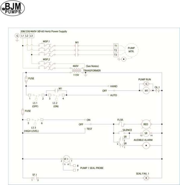
THREE PHASE WIRING DIAGRAMS ......................................................................................................................... |
30 |
208V........................................................................................................................................................................ |
30 |
MODELS SK08C, SKX08CSS, SK15C, SKX15CSS, SK22C, SKX22CSS, SK37C, SKX37CSS, SK55C, |
|
SKX55CSS, ........................................................................................................................................................30 |
|
230V........................................................................................................................................................................ |
31 |
MODELS SK08C, SKX08CSS, SK15C, SKX15CSS, SK22C, SKX22CSS, SK37C, SKX37CSS, SK55C, |
|
SKX55CSS, SKX75C, SKX75CSS, SK110C, SKX110CSS ............................................................................... |
31 |
460V........................................................................................................................................................................ |
32 |
MODELS SK08C, SKX08CSS, SK15C, SKX15CSS, SK22C, SKX22CSS, SK37C, SKX37CSS, SK55C, |
|
SKX55CSS, SKX75C, SKX75CSS, SK110C, SKX110CSS, SK150C, SKX150CSS ......................................... |
32 |
575V........................................................................................................................................................................ |
33 |
MODELS SK08C, SKX08CSS, SK15C, SKX15CSS, SK22C, SKX22CSS, SK37C, SKX37CSS, SK55C, |
|
SKX55CSS, SKX75C, SKX75CSS, SK110C, SKX110CSS, SK150C, SKX150CSS ......................................... |
33 |
SEAL MINDER® .......................................................................................................................................................... |
34 |
WARRANTY AND LIMITATION OF LIABILITY............................................................................................................ |
36 |
START-UP REPORT FORM........................................................................................................................................ |
37 |
NOTES:........................................................................................................................................................................ |
40 |
3

INTRODUCTION
This Installation, Operation and Maintenance manual provides important information on safety and the proper inspection, disassembly, assembly and testing of the BJM Pumps® SK & SKX Series submersible pump. This manual also contains information to optimize performance and longevity of your BJM Pumps submersible pump.
The submersible SK Series pumps are designed to pump wastewater and industrial wastewater that includes up to 10% by volume of solids. The SKX Series pumps are designed to pump corrosive liquids along with some solids in concentrations chemically compatible with 316SS and FKM. The SK & SKX Series pumps are not explosion-proof. They are not designed to pump volatile or flammable liquids.
Note: Consult chemical resistance chart for compatibility between pump materials and liquid before operating pump.
If you have any questions regarding the inspection, disassembly, and assembly or testing please contact your BJM Pumps distributor, or BJM Pumps, LLC.
BJM Pumps, LLC |
Phone: 877-256-7867 |
123 Spencer Plain Rd. |
Phone: 860-399-5937 |
Old Saybrook, CT 06475, USA |
Fax: 860-399-7784 |
Information, including pump data sheets and performance curves, is also available on our web site: www.bjmpumps.com
For assistance with your electric power source, please contact a certified electrician.
Please pay attention to the following alert notifications. They are used to notify operators and maintenance personnel to pay special attention to procedures, to avoid causing damage to the equipment, and to avoid situations that could be dangerous to personnel.
NOTE: Instructions to aid in installation, operation, and maintenance or which clarify a procedure.
 Immediate hazards that WILL result in severe personal injury or death. These instructions describe the procedure required and the injury which will result from failure to follow the procedure.
 Hazards or unsafe practices that COULD result in severe personal injury or death. These instructions describe the procedure required, and the injury which could result from failure to follow the procedure.
4

Hazards or unsafe practices which COULD result in personal injury or product or property damage. These instructions describe the procedure required and the possible damage which could result from failure to follow the procedure.
SAFETY
Pump installations are seldom identical. Each installation and application can vary due to many different factors. It is the owner/service mechanics responsibility to repair, service, and test to ensure that the pump integrity is not compromised according to this manual.
 Risk of electric shock – this pump has not been investigated for use in swimming pool areas.
 Do not pump flammable, inflammable or volatile liquids. Death or serious injury will result.
Before attempting to open or service the pump:
1)Familiarize yourself with this manual.
2)Unplug or disconnect the pump power cable to ensure that the pump will remain inoperative.
3)Allow the pump to cool if overheated.
 Do not operate the pump with a worn or damaged electric power cable. Death or serious injury could occur.
 Never attempt to alter the length or repair any power cable with a splice. The pump motor and pump motor and cable must be completely waterproof. Damage to the pump or personal injury may result from alterations.
 After the pump has been installed, make sure that the pump and all piping are secure before operation.
 Do not lift the pump by the power cable piping or discharge hose. Attach proper lifting equipment to the lifting handle (or lifting rings) fitted to the pump. Do not suspend the pump by the power cable.
 Obtain the services of a qualified electrician to troubleshoot, test and/or service the electrical components of this pump.
5

Pumps and related equipment must be installed and operated according to all national, local and industry standards.
INSPECTION
Review all safety information before servicing pump.
The following are recommended installation practices/procedures for the pump. If there are questions in regards to your specific application, contact your local BJM Pumps distributor or BJM Pumps, LLC.
PRE-INSTALLATION INSPECTION
1)Check the pump for damage that may have occurred during shipment.
2)Inspect the pump for any cracks, dents, damaged threads, etc.
3)Check power cord (and Seal Minder® cord, if installed) for any cuts or damage.
4)Check for, and tighten any hardware that appears loose.
5)Carefully read all tags, decals and markings on the pump.
6)Important: Always verify that the pump nameplate amps, voltage, phase, and HP ratings match your control panel and power supply.
Warranty does not cover damage caused by connecting pumps and controls to an incorrect power source (voltage/phase supply).
Record the model numbers and serial numbers from the pumps and control panel on the front of this instruction manual for future reference. Give it to the owner or affix it to the control panel when finished with the installation.
If anything appears to be abnormal, contact your BJM Pumps distributor or BJM Pumps, LLC. If damaged, the pump may need to be repaired before use. Do not install or use the pump until appropriate action has been taken.
Lubrication:
No additional lubrication is necessary. The shaft seal and bearings are fully lubricated from the factory. Seal oil should be checked once per year. See table: Oil Fill Quantity / Type.
6

OIL FILL QUANTITY/TYPE
|
|
|
OIL IN SEAL CHAMBER |
|
|
|
|
MODEL |
U.S. FL. OZ. |
CC. |
TYPE OF OIL |
|
|
|
|
SK750C |
7.8 |
230 |
ISO 32 NSF Food Grade Mineral Oil |
SK750C-3 |
7.8 |
230 |
ISO 32 NSF Food Grade Mineral Oil |
SK1500C |
7.8 |
230 |
ISO 32 NSF Food Grade Mineral Oil |
SK08C |
7.8 |
230 |
ISO 32 NSF Food Grade Mineral Oil |
SK08C-3 |
7.8 |
230 |
ISO 32 NSF Food Grade Mineral Oil |
SK15C |
7.8 |
230 |
ISO 32 NSF Food Grade Mineral Oil |
SK22C |
11.8 |
350 |
ISO 32 NSF Food Grade Mineral Oil |
SK37C |
11.8 |
350 |
ISO 32 NSF Food Grade Mineral Oil |
SK55C |
84.5 |
2500 |
ISO 32 NSF Food Grade Mineral Oil |
SK75C |
84.5 |
2500 |
ISO 32 NSF Food Grade Mineral Oil |
SK110C |
87.9 |
2600 |
ISO 32 NSF Food Grade Mineral Oil |
SK150C |
87.9 |
2600 |
ISO 32 NSF Food Grade Mineral Oil |
|
|
|
OIL IN SEAL CHAMBER |
||
|
|
|
|
|
|
MODEL |
|
U.S. FL. OZ. |
CC. |
|
TYPE OF OIL |
|
|
|
|
|
|
SKX750CSS |
|
10.1 |
300 |
ISO 32 NSF Food Grade Mineral Oil |
|
SKX750CSS-3 |
|
10.1 |
300 |
ISO 32 NSF Food Grade Mineral Oil |
|
SKX1500CSS |
|
10.1 |
300 |
ISO 32 NSF Food Grade Mineral Oil |
|
SKX08CSS |
|
10.1 |
300 |
ISO 32 NSF Food Grade Mineral Oil |
|
SKX08CSS-3 |
|
10.1 |
300 |
ISO 32 NSF Food Grade Mineral Oil |
|
SKX15CSS |
|
10.1 |
300 |
ISO 32 NSF Food Grade Mineral Oil |
|
SKX22CSS |
|
13.5 |
400 |
ISO 32 NSF Food Grade Mineral Oil |
|
SKX37CSS |
|
13.5 |
400 |
ISO 32 NSF Food Grade Mineral Oil |
|
SKX55CSS |
|
84.5 |
2500 |
ISO 32 NSF Food Grade Mineral Oil |
|
SKX75CSS |
|
84.5 |
2500 |
ISO 32 NSF Food Grade Mineral Oil |
|
SKX110CSS |
|
87.9 |
2600 |
ISO 32 NSF Food Grade Mineral Oil |
|
SKX150CSS |
|
87.9 |
2600 |
ISO 32 NSF Food Grade Mineral Oil |
|
Note: EPDM seals will use Propylene glycol instead of Shell FM32 oil
PUMP INSTALLATION
SK & SKX Series pumps have been evaluated for use with water or water based solutions with some solids. Please contact the manufacturer for additional information.
The Shredder pumps (1 and 2 HP) are not designed to pump unscreened solids which could contain matter such as bunched paper towels, feminine napkins, tampon applicators, etc. This type of debris can clog the pump & prevent it from operating properly. The BJM Pumps Shredder Pumps (7.5 HP and larger) are designed to handle unscreened sewage.
7
Risk of electric shock. Pump models; SK750C, SK750C-3, SKX750CSS & SK750CSS-3 (115v) are supplied with a grounding conductor and grounding-type attachment plug. All 230V single phase pumps and all three phase pumps do not come with electric plug connectors. To reduce the risk of electric shock, be certain that it is connected only to a properly grounded, grounding-type receptacle.
Lifting:
Attach a rope or lifting chain (not included) to the handle (or lifting rings) on the top of the pump.
 Do not lift the pump by the power cable or discharge hose/piping. Proper lifting equipment (rope/chain) must be used.
POSITIONING THE PUMP
BJM Pumps, SK & SKX Series pumps are designed to operate fully or partially submerged. Avoid running the pump dry for extended periods of time. Refer to data sheet for minimum submersion depth for your particular model. Data sheets can be obtained online at www.bjmpumps.com or by calling BJM Pumps, LLC at 860-399-5937. As a general rule, SK and SKX Series SIDE discharge pumps can pump down to a level above the suction screen. Pumping lower than screen will permit air to enter the pump and cavitate, lose prime or become air bound.
Do not run pump dry.
Pump liquid should not exceed a maximum temperature of 104°F.
Never place the pump on loose or soft ground. The pump may sink, preventing water from reaching the impeller. Place on a solid surface or suspend the pump with a lifting rope/chain. The SK & SKX Series pumps are provided with a suction strainer to prevent large solids from clogging the impeller. Any spherical solids which pass through the strainer should pass through the pump.
For maximum pumping capacity, use the proper size non-collapsible hose or rigid piping. A check valve may be installed after the discharge to prevent back flow when the pump is shut off.
Take stand off of pump when using slide rail. Keep stand and reattach when transporting or handling the pump.
PUMP ROTATION
Two ways to check the correct pump rotation:
1.By looking at the impeller; the rotation of the impeller should be counter clockwise as shown in the picture below.
8
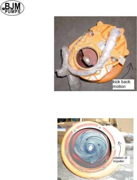
2.By looking from the top of the pump. Since the impeller cannot be seen, the best way to check the rotation is to check the kick back motion of the pump when the pump just starts. The kick back motion of the pump should be counter clockwise as shown in the picture below.
PUMP OPERATION
 This pump is designed to handle dirty water that contains some solids. It is not designed to pump volatile or flammable liquids. Do not attempt to pump any liquids which may damage the pump or endanger personnel as a result of pump failure.
 Do not operate this pump where explosive vapors or flammable material exist. Death or Serious injury will result.
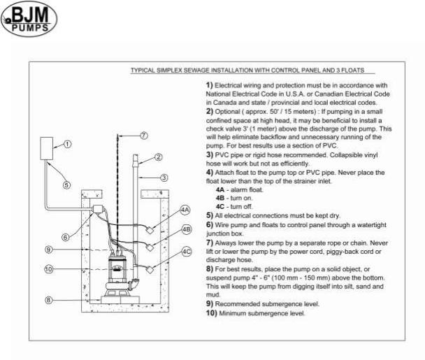
TYPICAL MUNICIPAL AND INDUSTRIAL WASTEWATER INTALLATION
NOTE: Maximum recommended starts should not exceed 10 times per hour.
9

MANUAL OPERATION
All SK & SKX Models are provided with a 33’ (10 m) power cord. NEVER splice the power cable due to safety and warranty considerations. Always keep the plug end dry.
Note: 230V, single phase and 208V, 230V, 460V & 575V three phase units do not have a plug and have to be provided separately.
 Do not alter the length or repair any power cable with a splice. The pump motor and cable must be completely waterproof. Damage to the pump or personal injury may result from alterations.
For manual operation: 115 volt: plug the power cable into any 115 volt grounded receptacle. 208, 230, 460 & 575 volt: Attach the proper plug, connect directly to the power source or control box. Check the direction of the rotation. Tilt the pump and start it. It should twist in the opposite direction of the arrow (on pump). It is recommended that a Ground Fault Interrupter (GFI) type receptacle (or equivalent) be used.
 Single phase pumps always use a three-prong grounded receptacle. It is recommended that a Ground Fault Interrupter (GFI) type receptacle (or equivalent) be used.

STOPPING
To stop the pump (manual and automatic mode), unplug it from the power source, turn off the breaker, or turn the power source off (generator).
Typical 3 phase manual control 1
11
TYPICAL MUNICIPAL OR INDUSTRIAL WASTEWATER INSTALLATION
NOTE: Maximum recommended starts should not exceed 10 times per hour.
AUTOMATIC OPERATION
Float switches (wired into the pump motor or piggy-back style) are available from the factory as an option.
Note: 208V, 230V, 460V & 575V pumps do not have a plug installed.
Three phase pumps need a separate control box with float(s) for automatic operation.
STOPPING
To stop the pump (manual and automatic mode), unplug it from the power source, turn off the breaker, or turn the power source off (generator).
12
Typical 3 phase Auto Control 1
INTENDED METHODS OF CONNECTION
 Use with approved motor control that matches motor input in full load amperes. “UTILLISER UN DÉMARREAR APPROUVÉ CONVENANT AU COURANT Á PLEINE CHARGE DU MOTEUR.”
BJM Pumps has been evaluated for use with water or water based solutions. Please contact the manufacturer for additional information.
SINGLE PHASE WIRING INSTRUCTIONS
 FOR YOUR PROTECTION, ALWAYS DISCONNECT PUMP FROM ITS POWER SOURCE BEFORE HANDLING. Single phase pumps are supplied with a three prong grounded plug to help protect you against the possibility of electrical
13
 Loading...