

Page 1

User’s Manual
SRP-350/352plusIIA&C
Thermal Printer
Rev. 1.00
http://www.bixolon.com
Page 2

SRP-350/352plusIIA&C
■ Safety Precautions
In using the present appliance, please keep the following safety regulations in order to
prevent any hazard or material damage.
WARNING
Violating following instructions can cause serious injury or death.
Do not plug several products in one multi-outlet.
• This can provoke over-heating and a fire.
• If the plug is wet or dirty, dry or wipe it before usage.
• If the plug does not fit perfectly with the outlet, do not plug in.
• Be sure to use only standardized multi-outlets.
PROHIBITED
Do not pull the cable to unplug.
• This can damage the cable, which is the origin of a fire or a
breakdown of the printer.
PROHIBITED
You must use only the supplied adapter.
• It is dangerous to use other adapters.
ONLY SUPPLIED ADAPTER
PROHIBITED
Keep the plastic bag out of children’s reach.
• If not, a child may put the bag on his head.
PROHIBITED
Do not plug in or unplug with your hands wet.
• You can be electrocuted.
PROHIBITED
Rev. 1.00
Do not bend the cable by force or leave it under any
heavy object.
• A damaged cable can cause a fire.
PROHIBITED
- 2 -
Page 3

SRP-350/352plusIIA&C
CAUTION
Violating following instructions can cause slight wound or damage the appliance.
If you observe a strange smoke, odor or noise from
the printer, unplug it before taking following
measures.
• Switch off the printer and unplug the set from the mains.
• After the disappearance of the smoke, call your dealer to
repair it.
TO UNPLUG
PRINTER
Install the printer on the stable surface.
• If the printer falls down, it can be broken and you can hurt
yourself.
PRINTER
PROHIBITED
Keep the desiccant out of children’s reach.
• If not, they may eat it.
PROHIBITED
Use only approved accessories and do not try to
disassemble, repair or remodel it for yourself.
• Call your dealer when you need these services.
• Do not touch the blade of auto cutter.
DISASSEMBLING
PROHIBITED
PRINTER
Do not let water or other foreign objects in the
printer.
• If this happened, switch off and unplug the printer before
calling your dealer.
PROHIBITED
PRINTER
Do not use the printer when it is out of order. This
can cause a fire or an electrocution.
• Switch off and unplug the printer before calling your dealer.
TO UNPLUG
PRINTER
DEALER
Rev. 1.00
- 3 -
Page 4

SRP-350/352plusIIA&C
■ Warning - U.S.A
This equipment has been tested and found to comply with the limits for a Class A digital
device pursuant to Part 15 of the FCC Rules. These limits are designed to provide
reasonable protection against harmful interference when the equipment is operated in a
commercial environment. This equipment generates uses, and can radiate radio frequency
energy and, if not installed and used in accordance with the instruction manual, may cause
harmful interference to radio communications. Operation of this equipment in a residential
area is likely to cause harmful interference in which case the user will be required to
correct the interference at his own expense.
■ Notice - Canada
This Apparatus complies with class “A” limits for radio interference as specified in the
Canadian department of communications radio interference regulations.
Get appareil est conforme aux normes class “A” d’interference radio tel que specifier par
ministre canadien des communications dans les reglements d’interference radio.
■ Caution
Some semiconductor devices are easily damaged by static electricity. You should turn the
printer “OFF”, before you connect or remove the cables on the rear side, in order to guard
the printer against the static electricity. If the printer is damaged by the static electricity, you
should turn the printer “OFF”.
■ Waste Electrical and Electric Equipment (WEEE)
This marking shown on the product or its literature, indicates that is should not
be disposed with other household wastes at the end of its working life, To
prevent possible harm to the environment or human health from uncontrolled
waste disposal, please separate this from other types of wastes and recycle it
responsibly to promote the sustainable reuse of material resources. Household
users should contact either the retailer where they purchased this product, or
their local government office, for details of where and how they can take this item for
environmentally safe recycling. Business users should contact their supplier and check the
terms and conditions of the purchase contract. This product should not be mixed with other
commercial wastes for disposal.
■ Label Material
* Control Label: PC
* Other Labels: PET
Rev. 1.00
- 4 -
Page 5

SRP-350/352plusIIA&C
■ Introduction
The SRP-350/352plusII Roll Printer are designed for use with electronic instruments such
as system ECR, POS, banking equipment, computer peripheral equipment, etc.
The main features of the printer are as follows:
1. High speed printing : 59 (1/6” Feed) lines per second.
2. Low noise thermal printing.
3. The data buffer allows the unit to receive print data even during printing.
4. Peripheral units drive circuit enables control of external devices such as cash drawer.
5. Characters can be scaled up to 64 times compared to it’s original size.
6. Bar code printing is possible by using a bar code command.
7. Different print densities can be selected by DIP switches.
Please be sure to read the instruction in this manual carefully before using your new
SRP-350/352plusII.
※ NOTE
The socket-outlet shall be near the equipment and it shall be easy accessible.
※ All specifications are subjected to change without notice.
We at BIXOLON maintain ongoing efforts to enhance and upgrade the functions and
quality of all our products. In following, product specifications and/or user manual content
may be changed without prior notice.
Rev. 1.00
- 5 -
Page 6

SRP-350/352plusIIA&C
■ Table of Contents
1. Setting Up the Printer ..................................................................................................7
1-1 Unpacking.................................................................................................................7
1-2 Connecting the Cables .............................................................................................8
1-2-1 Serial Interface (RS-232C) ...........................................................................8
1-2-2 Parallel Interface (IEEE1284) .......................................................................9
1-2-3 USB2.0 Interface ........................................................................................10
1-3 Connecting the Drawer ...........................................................................................10
1-4 Setting the Dip Switches.........................................................................................11
1-4-1 Serial Interface (RS-232C) ......................................................................... 11
1-4-2 Parallel & USB2.0 Interface........................................................................ 11
1-4-3 Auto Cutter Enable / Disable selection .......................................................12
1-5 Setting the Memory Switches .................................................................................13
1-6 Installing or Replacing the Paper Roll.....................................................................16
1-7 Adjustments and Settings .......................................................................................18
1-8 Using the Printer.....................................................................................................18
1-9 Connecting the computer........................................................................................19
1-10 Connecting the Power Supply ..............................................................................19
2. Self test.......................................................................................................................20
3. Hexadecimal Dumping ..............................................................................................21
4. Specification ..............................................................................................................22
5. Appendix ....................................................................................................................23
5-1 Cleaning Printer......................................................................................................23
5-2 Using Wall Mount....................................................................................................23
Rev. 1.00
- 6 -
Page 7

SRP-350/352plusIIA&C
1. Setting Up the Printer
1-1 Unpacking
Your printer box should include these items. If any items are damaged or missing, please
contact your dealer for assistance.
SRP-350/352plusIIC SRP-350/352plusIIA Cover Cable
Roll Paper Manual AC Adapter Power Cord
CD USB A-A CABLE
Rev. 1.00
- 7 -
Page 8
SRP-350/352plusIIA&C
1-2 Connecting the Cables
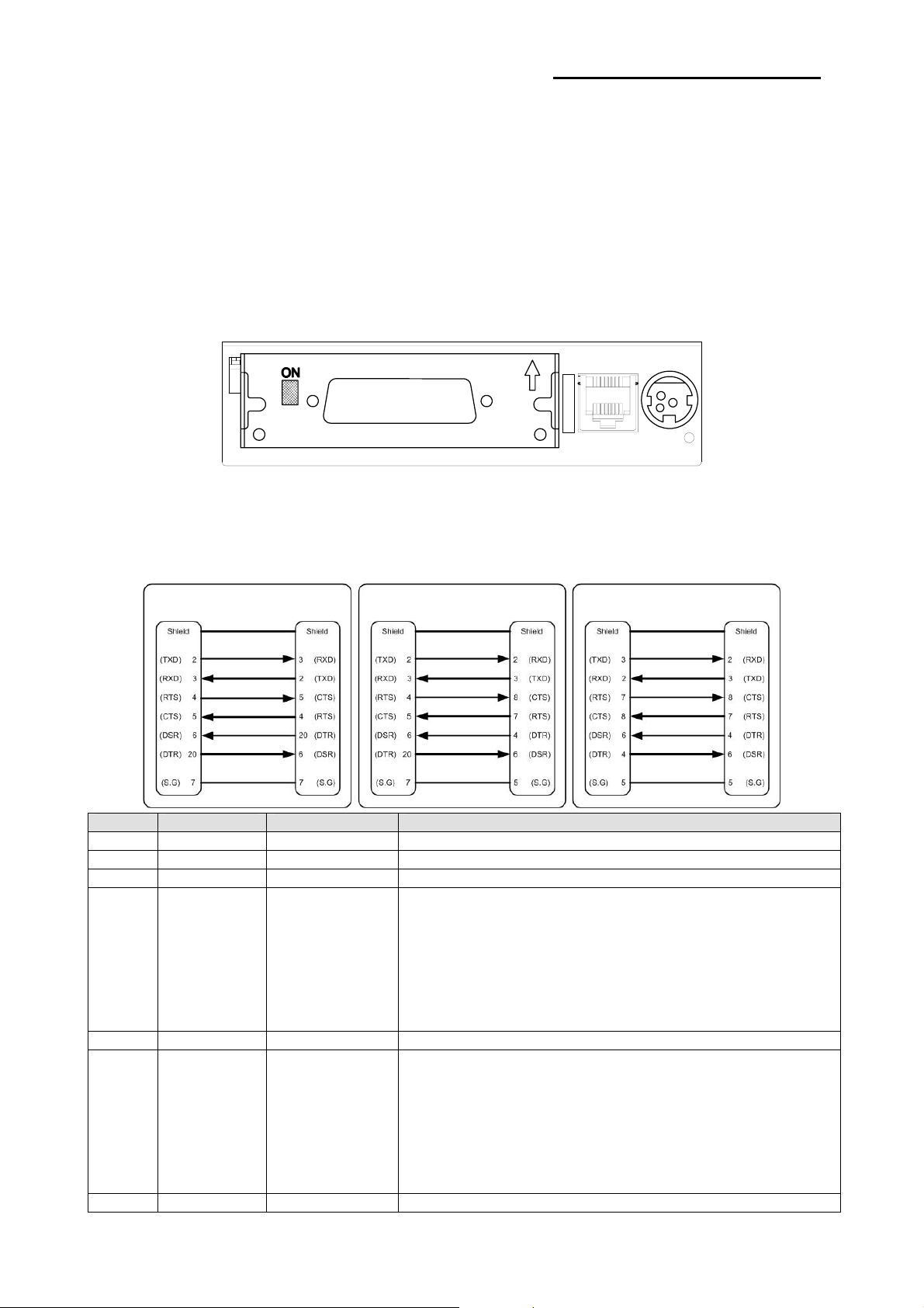
You can connect up the three cables to the printer. They all connect to the connector panel
on the back of the printer, which is shown below:
※ NOTE
Before connecting any of the cables, make sure that both the printer and the host are
turned off.
1-2-1 Serial Interface (RS-232C)
Interface connector
※ When the Dip Switch is “ON” on the Serial Interface Board,
PRINTER
SIDE (25P)
DTR and RTS are connected each other.
HOST
SIDE (25P)
PRINTER
SIDE (25P)
HOST
SIDE (9P)
Drawer
kick-out
connector
PRINTER
SIDE (9P)
Power
supply
connector
HOST
SIDE (9P)
Pin No. Signal Name Signal Direction Function
BODY Frame GND - Frame Ground
2 TXD Output Transmit Data
3 RXD Input Receive Data
This signal indicates whether the host computer can receive
data. (H/W flow control)
1) MARK(Logic1) : The host can receive a data.
6 DSR Input
7 Signal GND - Signal Ground
20 DTR Output
Shield Frame GND - Frame Ground
Rev. 1.00
2) SPACE(Logic0) : The host can not receive a data.
3) The printer transmits a data to the host, after confirming
this signal.
4) When XON/XOFF flow control is selected, the printer
does not check this signal.
This signal indicates whether the printer is busy. (H/W flow
control)
1) MARK(Logic1) : The printer is busy.
2) SPACE(Logic0) : The printer is not busy.
3) The host transmits a data to the printer, after confirming
this signal.
4) When XON/XOFF flow control is selected, the host does
not check this signal.
- 8 -
Page 9
SRP-350/352plusIIA&C
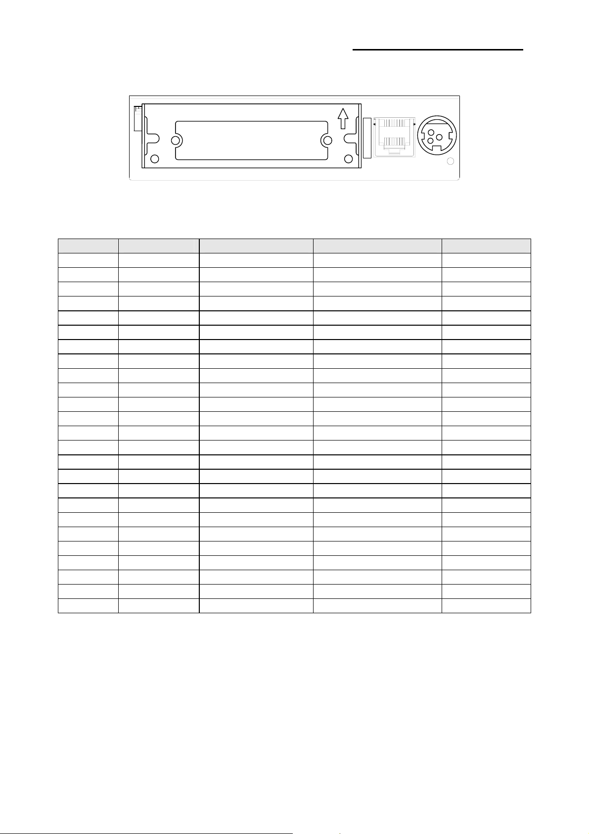
1-2-2 Parallel Interface (IEEE1284)
Interface connector
Pin No. Source Compatibility Mode Nibble Mode Byte Mode
1 Host nStrobe HostClk HostClk
2 Host / Printer Data 0 (LSB) - Data 0 (LSB)
3 Host / Printer Data 1 - Data 1
4 Host / Printer Data 2 - Data 2
5 Host / Printer Data 3 - Data 3
6 Host / Printer Data 4 - Data 4
7 Host / Printer Data 5 - Data 5
8 Host / Printer Data 6 - Data 6
9 Host / Printer Data 7 (MSB) - Data 7 (MSB)
10 Printer nAck PtrClk PtrClk
11 Printer Busy PtrBusy /Data3,7 PtrBusy
12 Printer Perror AckDataReq/Data2,6 AckDataReq
13 Printer Select Xflag /Data1,5 Xflag
14 Host nAutoFd HostBusy HostBusy
15 NC NC NC
16 GND GND GND
17 FG FG FG
18 Printer Logic-H Logic-H Logic-H
19~30 GND GND GND
31 Host nInit nInit nInit
32 Printer nFault nDataAvail /Data0,4 nDataAvail
33 GND ND ND
34 Printer DK_Status ND ND
35 Printer +5V ND ND
36 Host nSelectIn 1284-Active 1284-Active
Drawer
kick-out
connector
Power
supply
connector
Rev. 1.00
- 9 -
Page 10
SRP-350/352plusIIA&C
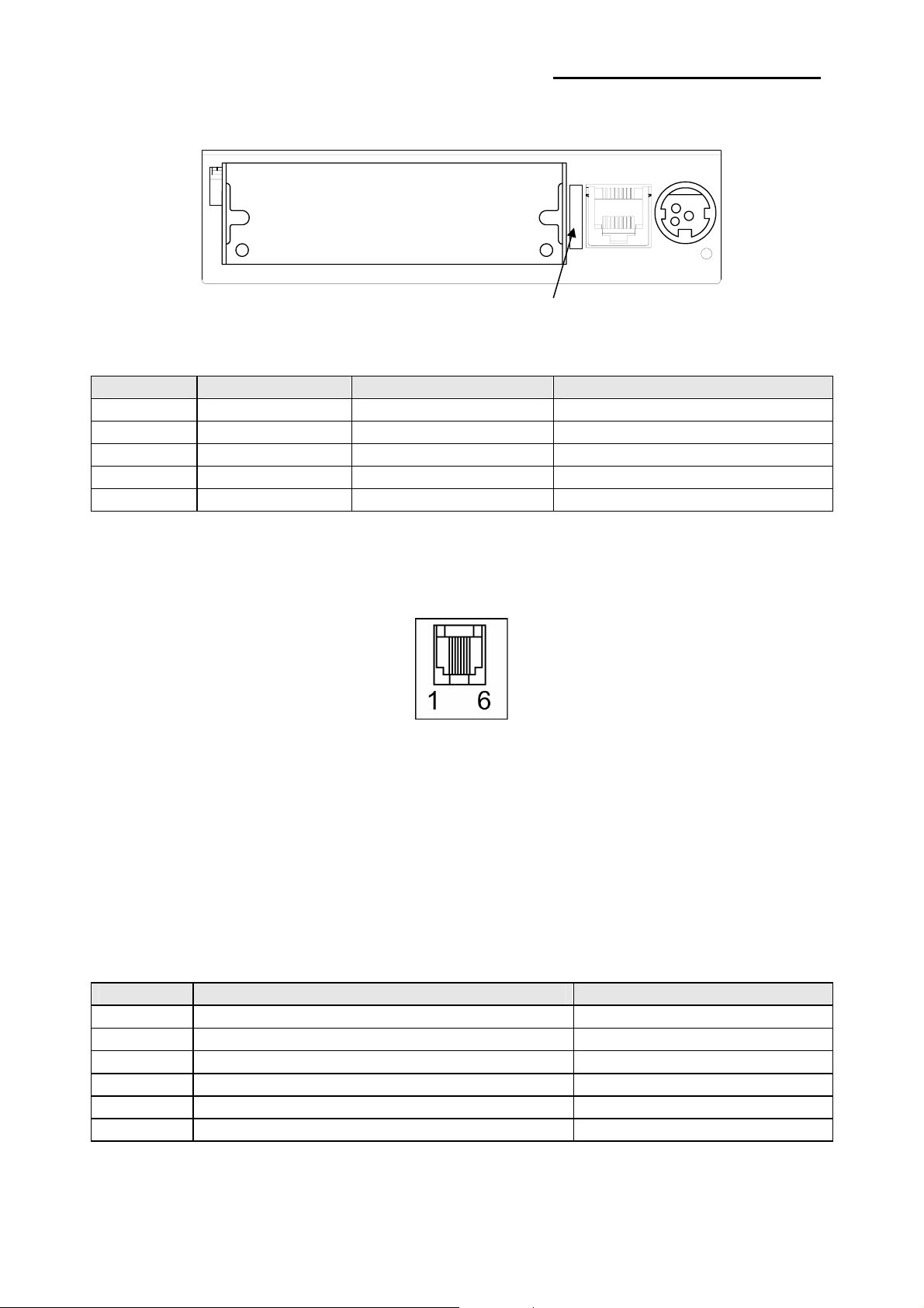
1-2-3 USB2.0 Interface
USB2.0 connector
Pin No. Signal Name Assignment (Color) Function
Shell Shield Drain Wire Frame Ground
1 VBUS Red Host Power : DC5[V] / 500[mA]
2 D- White Differential Data Line
3 D+ Green Differential Data Line
4 GND Black Signal Ground
1-3 Connecting the Drawer
Drawer
kick-out
connector
Power
supply
connector
※ WARNING
Use a drawer that matches the printer specification. Using an improper drawer may
damage the drawer as well as the printer.
※ CAUTION
Do not connect a telephone line to the drawer kick-out connector; otherwise the printer and
the telephone line may be damaged.
Plug the drawer cable into the drawer kick-out connector on the back of the printer next to
the power supply connector.
Pin No. Signal name Direction
1 Frame ground 2 Drawer kick- out drive signal 1 Output
3 Drawer open/close signal Input
4 +24V 5 Drawer kick- out drive signal 2 Output
6 Signal ground -
※ Drawer Port is 24Vdc/2.5A Output rating, Class 1.
Rev. 1.00
- 10 -
Page 11
SRP-350/352plusIIA&C
1-4 Setting the Dip Switches
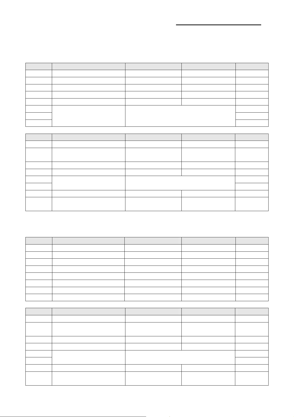
1-4-1 Serial Interface (RS-232C)
• DIP Switch 1
SW Function ON OFF Default
1-1 Auto Line Feed Enable Disable OFF
1-2 Flow Control XON/XOFF DTR/DSR OFF
1-3 Data Length 7 bits 8 bits OFF
1-4 Parity Check Yes No OFF
1-5 Parity Selection EVEN ODD OFF
1-6 OFF
1-7 ON
1-8
• DIP Switch 2
SW Function ON OFF Default
2-1 Auto cutter control Full cut Partial cut OFF
2-2 Internal bell control Internal bell disable
2-3 Auto Cutter Auto cutter disable Auto cutter enable OFF
2-4 Reserved - - OFF
2-5 OFF
2-6
2-7 Near-End Sensor Status Disable Enable OFF
2-8 External buzzer control
1-4-2 Parallel & USB2.0 Interface
• DIP Switch 1
SW Function ON OFF Default
1-1 Auto Line Feed Enable Disable OFF
1-2 Reserved - - OFF
1-3 Reserved - - OFF
1-4 Reserved - - OFF
1-5 Reserved - - OFF
1-6 Reserved - - OFF
1-7 Reserved - - ON
1-8 Reserved - - OFF
• DIP Switch 2
SW Function ON OFF Default
2-1 Auto cutter control Full cut Partial cut OFF
2-2 Internal bell control Internal bell disable
2-3 Auto Cutter Auto cutter disable Auto cutter enable OFF
2-4 Reserved - - OFF
2-5 OFF
2-6
2-7 Near-End Sensor Status Disable Enable OFF
2-8 External buzzer control
Baud rate Selection (bps) Refer to the following Table 1
Internal bell
enable
Print Density Refer to the following table 2
External buzzer
enable
External buzzer
disable
Internal bell
enable
Print Density Refer to the following table 2
External buzzer
enable
External buzzer
disable
OFF
OFF
OFF
OFF
OFF
OFF
OFF
Rev. 1.00
- 11 -
Page 12
SRP-350/352plusIIA&C
• Table 1 – Baud rate (bps) Selection
Transmission Speed 1-6 1-7 1-8 Default
2400 ON OFF OFF
4800 ON OFF ON
9600 OFF ON OFF
19200 OFF OFF OFF
38400 OFF ON ON
57600 OFF OFF ON
115200 ON ON ON
• Table 2 – Print Density Selection
Print Density 2-5 2-6 Default
1 (Light) ON ON
2 (Medium) OFF OFF
3 (Dark) OFF ON
1-4-3 Auto Cutter Enable / Disable selection
Dip Switch Set 2
SW 2-3
Application Ignores Auto Cutter error for continuous printing.
ON Auto Cutter Disabled
OFF Auto Cutter Enabled
9600
2
Rev. 1.00
- 12 -
Page 13
SRP-350/352plusIIA&C
1-5 Setting the Memory Switches
This printer has “Memory Switch” set which is software switches. Memory Switch set has
“MSW1”, “MSW2”, “MSW8”, “MSW9” “Customize value”, “Serial communication condition”.
“Memory Switch setting utility” can change the Memory Switch set to ON or OFF as shown
in the table below. (default : all OFF)
※ NOTE
The Memory Switch is available to be changed by three methods.
- Memory Switch setting utility.
- Control from BXL/POS command.
Settings of the Memory Switch are stored in the NV memory : therefore, even if the printer
is turned off, the settings are maintained.
MSW1
Switch Function ON OFF
1
2
3~8 Reserved -- Fixed to OFF
180dpi
MSW 1-2 MSW 1-1 Print Density Remark
OFF OFF Print Density 3 250mm/s
OFF ON Print Density 2 230mm/s
ON OFF Print Density 1 200mm/s
203dpi
MSW 1-2 MSW 1-1 Print Density Remark
OFF OFF Print Density 3 230mm/s
OFF ON Print Density 2 200mm/s
ON OFF Print Density 1 180mm/s
MSW2
Switch Function ON OFF
1
2 Reserved -- Fixed to OFF
3
4
5
6
7
8
Select Print Speed Refer to following Table
Specification for
Destination
Code Page Selection Refer to following Table
Double byte Country Single byte Country
Rev. 1.00
- 13 -
Page 14
SRP-350/352plusIIA&C
MSW2-8 MSW2-7 MSW2-6 MSW2-5 MSW2-4 MSW2-3 Character Table
OFF OFF OFF OFF OFF OFF Page 0 437 (USA, Standard Europe)
OFF OFF OFF OFF ON OFF Page 1 Katakana
OFF OFF OFF ON OFF OFF Page 2 850 (Multilingual)
OFF OFF OFF ON ON OFF Page 3 860 (Portuguese)
OFF OFF ON OFF OFF OFF Page 4 863 (Canadian-French)
OFF OFF ON OFF ON OFF Page 5 865 (Nordic)
OFF OFF ON ON OFF OFF Page 16 1252 (Latin I)
OFF OFF ON ON ON OFF Page 17 866 (Cyrillic #2)
OFF ON OFF OFF OFF OFF Page 18 852 (Latin 2)
OFF ON OFF OFF ON OFF Page 19 858 (Euro)
OFF ON OFF ON OFF OFF Page 21 862 (Hebrew DOS code)
OFF ON OFF ON ON OFF Page 22 864 (Arabic)
OFF ON ON OFF OFF OFF Page 23 Thai42
OFF ON ON OFF ON OFF Page 24 1253 (Greek)
OFF ON ON ON OFF OFF Page 25 1254 (Turkish)
OFF ON ON ON ON OFF Page 26 1257 (Baltic)
ON OFF OFF OFF OFF OFF Page 27 Farsi
ON OFF OFF OFF ON OFF Page 28 1251 (Cyrillic)
ON OFF OFF ON OFF OFF Page 29 737 (Greek)
ON OFF OFF ON ON OFF Page 30 775 (Baltic)
ON OFF ON OFF OFF OFF Page 31 Thai14
ON OFF ON OFF ON OFF Page 32 Hebrew Old code
ON OFF ON ON OFF OFF Page 33 1255 (Hebrew New code)
ON OFF ON ON ON OFF Page 34 Thai11
ON ON OFF OFF OFF OFF Page 35 Thai18
ON ON OFF OFF ON OFF Page 36 855 (Cyrillic)
ON ON OFF ON OFF OFF Page 37 857 (Turkish)
ON ON OFF ON ON OFF Page 38 928 (Greek)
ON ON ON OFF OFF OFF Page 39 Thai16
ON ON ON OFF ON OFF Page 40 1256 (Arabic)
ON ON ON ON OFF OFF Page 41 1258 (Vietnam)
ON ON ON ON ON OFF Page 42 Khmer (Cambodia)
OFF OFF ON OFF OFF ON Page 47 1250 (Czech)
MSW3
Switch Function ON OFF
1
2
Select Emulation Refer to following Table
3
4~8 Reserved -- Fixed to OFF
MSW 3-3 MSW 3-2 MSW 3-1 Emulation Remark
OFF OFF OFF Emulation 1 ESC / POS
OFF OFF ON Emulation 2
OFF ON OFF Emulation 3
OFF ON ON Emulation 4
ON OFF OFF Emulation 5
Rev. 1.00
- 14 -
Page 15
SRP-350/352plusIIA&C
MSW4
Switch Function ON OFF
1 Reserved -- Fixed to OFF
2 Reserved -- Fixed to OFF
3
4
5~8 Reserved -- Fixed to OFF
MSW 4-4 MSW 4-3 Single byte Font Selection Remark
OFF OFF Font A 12 x 24
OFF ON Font B 9 x 17
ON OFF Font C 9 x 24
ON ON -- Fixed to OFF
MSW5
Switch Function ON OFF
1~2 Reserved -- Fixed to OFF
3 2Color support Enable Disable
4~6 Reserved -- Fixed to OFF
7 2inch Left mode Enable Disable
8 2inch Center mode Enable Disable
MSW6
Switch Function ON OFF
1 Auto internal buzzer after cutting Enable Disable
2 Auto internal buzzer option 1 time 3 time
3
4 Auto external buzzer after cutting Enable Disable
5~8 Reserved -- Fixed to OFF
MSW11
Switch Function ON OFF
1~8 Reserved -- Fixed to OFF
Single byte Font Selection Refer to following Table
Auto internal buzzer with cash
drawer
Enable Disable
Rev. 1.00
- 15 -
Page 16
SRP-350/352plusIIA&C
1-6 Installing or Replacing the Paper Roll
※ NOTE
Be sure to use paper rolls that meet the specifications. Do not use paper rolls that have
the paper glued to the core because the printer cannot detect the paper end correctly.
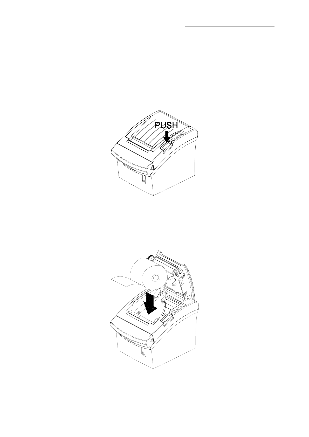
1-6-1 Make sure that the printer is not receiving data; otherwise, data may be lost.
1-6-2 Open the paper roll cover by pressing the cover-open button.
※ NOTE
Do not open the print cover while the printer is operating. This may damage the printer.
1-6-3 Remove the used paper roll core if there is one.
1-6-4 Insert the paper roll as shown.
Rev. 1.00
- 16 -
Page 17
SRP-350/352plusIIA&C
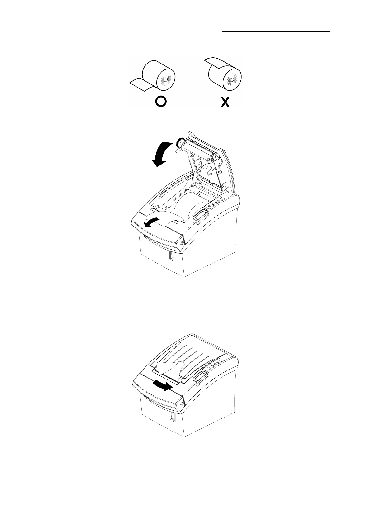
1-6-5 Be sure to note the correct direction that the paper comes off the roll.
1-6-6 Pull out a small amount of paper, as shown. Then close the cover.
※ NOTE
When closing the cover, press the center of printer cover firmly to prevent
paper miss-loading.
1-6-7 Tear off the paper as shown.
Rev. 1.00
- 17 -
Page 18
SRP-350/352plusIIA&C
1-7 Adjustments and Settings
The SRP-350/352plusII is set up at the factory to be appropriate for almost all users. It
does, however, offer some settings for users with special requirements.
It has DIP switches that allow you to change communication settings, such as
handshaking and parity check, as well as print density.
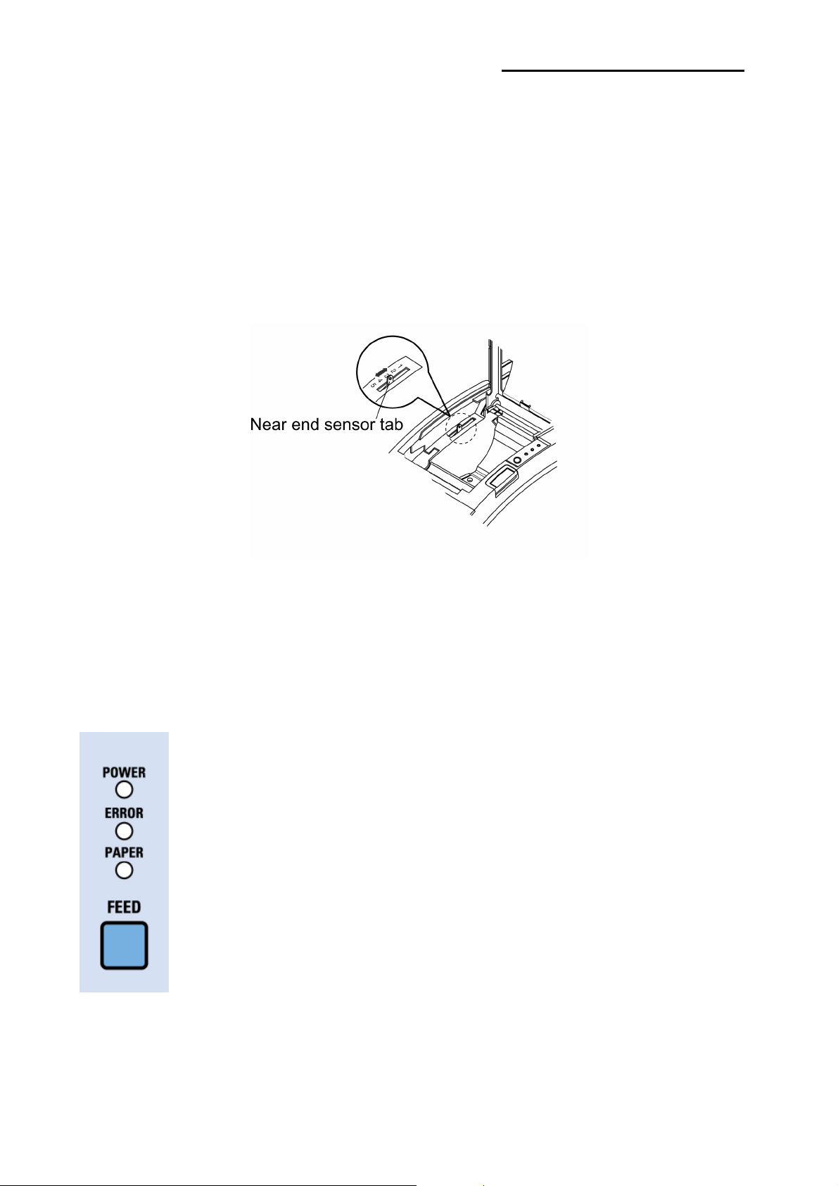
The SRP-350/352plusII also has a near-end sensor for the paper. This can give you a
warning when the paper is almost out. If you find that there is not enough paper remaining
on the roll when the near-end sensor is triggered, you can change the near-end sensor
setting. Rotate the near end sensor tab at front or rear position. (See the below figure)
1-8 Using the Printer
Control Panel
○ POWER
The POWER light is on whenever the printer is on.
○ ERROR
This indicates an error.
○ PAPER
This light indicates the near end of the paper roll. Install a new paper roll
and the printer Will continue printing. When the light blinks, it indicates
the self-test printing standby state or macro execution Standby state
when the macro execution command is used.
○ FEED
Press the FEED button once to advance paper one line. You can also
hold down the FEED button to feed paper continuously.
Rev. 1.00
- 18 -
Page 19
SRP-350/352plusIIA&C
1-9 Connecting the computer
You need an appropriate interface cable.
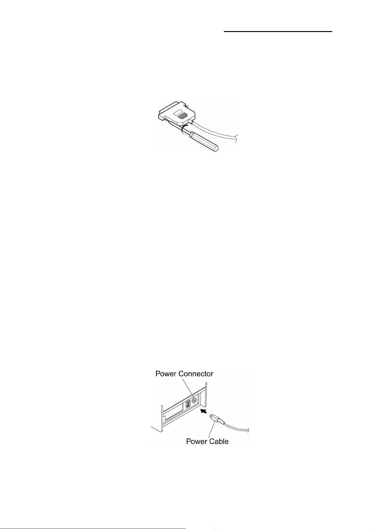
1-9-1 Plug the cable connector securely into the printer’s interface connector.
1-9-2 Tighten the screws on both sides of the cable connector.
1-9-3 Attach the other end of the cable to the computer.
1-10 Connecting the Power Supply
※ CAUTIONS
When connecting or disconnecting the power supply from the printer, make sure that the
power supply is not plugged into an electrical outlet. Otherwise you may damage the
power supply or the printer.
If the power supply’s rated voltage and your outlet’s voltage do not match, contact your
dealer for assistance. Do not plug in the power cord. Otherwise, you may damage the
power supply or the printer.
1-10-1 Make sure that the printer’s power switch is turned off, and the power supply’s
power cord is unplugged from the electrical outlet.
1-10-2 Check the label on the power supply to make sure that the voltage required by the
power supply matches that of your electrical outlet.
1-10-3 Plug in the power supply’s cable as shown below. Notice that the flat side of the
plug faces down.
※ NOTE
To remove the DC cable connector, make sure that the power supply’s power cord is
unplugged; then grasp the connector at the arrow and pull it straight out.
Rev. 1.00
- 19 -
Page 20

SRP-350/352plusIIA&C
2. Self test
The self-test checks whether the printer has any problems. If the printer does not function
properly, contact your dealer. The self-test checks the following;
2-1 Make sure paper roll has been installed properly.
2-2 Turn on the power while holding down the FEED button. The self-test begins.
2-3 The self-test prints the current printer status, which provides the control ROM version
and the DIP switch setting.
2-4 After printing the current printer status, self-test printing will print the following,
and pause (The PAPER LED light blinks).
SELF-TEST PRINTING.
PLEASE PRESS THE FEED BUTTON.
2-5 Press the FEED button to continue printing.
The printer prints a pattern using the built-in character set.
2-6 The self-test automatically ends and cuts the paper after printing the following.
*** COMPLETED ***
2-7 The printer is ready to receive data as soon as it completes the self-test.
Rev. 1.00
- 20 -
Page 21

SRP-350/352plusIIA&C
3. Hexadecimal Dumping
This feature allows experienced users to see exactly what data is coming to the printer.
This can be useful in finding software problems. When you turn on the hexadecimal dump
function, the printer prints all commands and data in hexadecimal format along with a
guide section to help you find specific commands.
To use the hexadecimal dump function, follow these steps.
3-1 After you make sure that the printer is off, open the cover.
3-2 Turn on the printer, while holding down the FEED button.
3-3 Close the cover, then the printer enters the hexadecimal dump mode.
3-4 Run any software program that sends data to the printer. The printer will print all the
codes it receives in a two-column format. The first column contains the hexadecimal
codes and the second column gives the ASCII characters that corresponds to the
codes.
1B 21 00 1B 26 02 40 40 40 40 . ! . . & . @ @ @ @
02 0D 1B 44 0A 14 1E 28 28 28 . . . D . . . . ( ( (
00 01 0A 41 0D 42 0A 43 43 43 . . . A . B . C C C
A period (.) is printed for each code that has no ASCII equivalent. During the hex
dump, all commands except DLE EOT and DLE ENQ are disabled.
3-5 When the printing finishes, turn off the printer.
3-6 Turn on the printer and then the hexadecimal mode is off.
Rev. 1.00
- 21 -
Page 22
SRP-350/352plusIIA&C
4. Specification
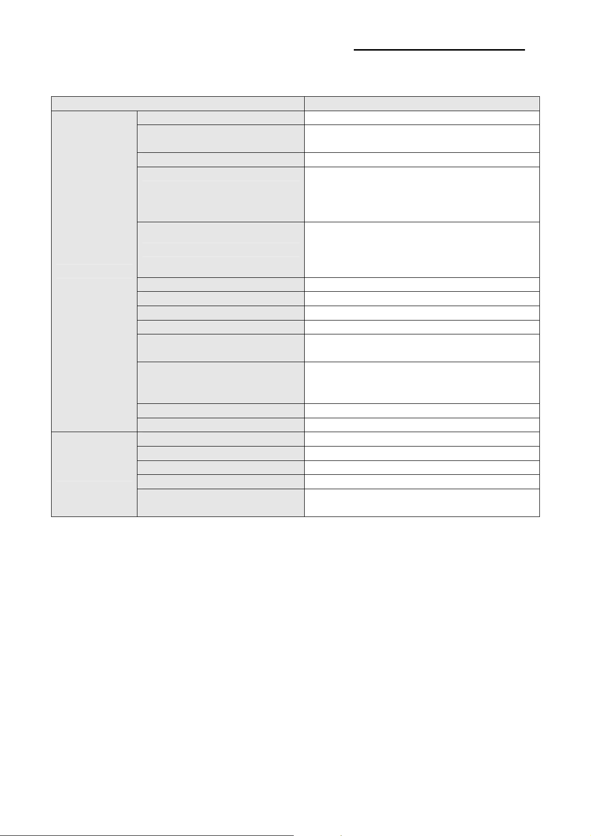
Item Details
Printing Method Thermal Line Printing
Dot Density
Printing Width 72mm
Characters per line
(Default)
Printing Speed *1)
Printer
Receive Buffer Size 4K Bytes
SMPS Input Voltage 100~240 VAC
Frequency 50/60 Hz
SMPS Output Voltage 24 VDC
Temperature
Humidity
Auto Cutter 1,800,000 Cuts
Mechanism MCBF *2) 70,000,000 Lines
Paper Type Paper Roll
Roll Width 80mm
Paper
Note※
*1) Printing speed may be slower depending on the data transmission speed and the
combination of control commands.
*2) The above values are calculated under printing level 2 with recommended paper at
normal temperature. The values may vary with environment temperature, printing
level, etc.
*3) The switch is the disconnecting device. Turn off switch from any hazard.
Roll Diameter Max 83mm
Paper Thickness 0.062~0.075mm
Paper Tube
SRP-350plusII: 180 dpi (7dots/mm)
SRP-352plusII: 203 dpi (8dots/mm)
SRP-350plusII
: 42 (Font A) / 56 (Font B) / 56 (Font C)
SRP-352plusII
: 48 (Font A) / 64 (Font B) / 64 (Font C)
SRP-350plusII
: 59.1 lines/sec, 250 mm/sec
SRP-352plusII
: 61.33 lines/sec, 230 mm/sec
0 ~ 45 (O℃ perating)
-20 ~ 60 (Storage)℃
10 ~ 80 % RH (Operating)
10 ~ 90 % RH (Storage)
; Except for paper
Inner: Ø12mm (0.47”)
Outer: Ø18mm (0.71”)
Rev. 1.00
- 22 -
Page 23

SRP-350/352plusIIA&C
5. Appendix
5-1 Cleaning Printer
Paper dust inside the printer may lower the print quality. In this case clean the printer as
follows.
5-1-1 Open the printer cover and remove the paper if exists.
5-1-2 Clean the print head with a cotton swab moistened with alcohol solvent.
5-1-3 Clean the platen roller and paper end sensor with cotton swab moistened with water.
5-1-4 Insert a paper roll and close the printer cover.
The remained amount of paper detected by paper near end sensor varies with the
diameter of the paper core.
To adjust the remained amount, contact your dealer.
5-2 Using Wall Mount
Please disable the near end paper function by making dip switch 2-7 on when you use the
printer in wall mount position where the near end paper function will not work well.
Rev. 1.00
- 23 -
 Loading...