

Page 1
BBTT--77550
0
Operational Manual
Distributor : BISTOS Co., Ltd.
th
7
FL., A Bldg., Woolim Lions Valley 5-cha, 302, Galmachi-ro, Jungwon-gu,
Seongnam-si, Gyeonggi-do , Korea
(Manufacturer) : INFUNIX Technology Co., Ltd.
2F, Joong-il B/D, 13, Wangsimni-ro 4ga-gil, Seongdong-gu, Seoul, Korea
Page 2

VER 1.0
BT-750 Operational Manual
Contents
GENERAL .............................................................................................................................................. 5
WARRANTY ........................................................................................................................................... 6
SERVICE REQUIREMENTS .................................................................................................................. 6
HOW TO CONTACT US ......................................................................................................................... 7
CH. 1 HOW TO USE THIS MANUAL .................................................................................................. 8
1.1 CONTENTS OF MANUAL .................................................................................................................... 8
1.2 MEANING OF SYMBOLS USED IN THIS MANUAL .................................................................................. 9
CH. 2 OPERATIONAL DO’S AND DON’TS ...................................................................................... 10
2.1 DON’TS IN OPERATIONAL ENVIRONMENT ......................................................................................... 10
2.2 CAUTIONS FOR ELECTRICAL SAFETY .............................................................................................. 11
2.3 CLASSIFICATIONS .......................................................................................................................... 11
2.4 MAINTENANCE AND CLEANING ........................................................................................................ 12
CH. 3 INTRODUCTION OF BT-750 .................................................................................................. 14
3.1 FEATURE BT-750 .......................................................................................................................... 14
3.2 COMPOSITION ............................................................................................................................... 14
3.3 COMPONENTS ............................................................................................................................... 15
3.4 DESCRIPTION OF PRODUCT SYMBOLS ............................................................................................ 19
3.5 DESCRIPTION OF EQUIPMENT SYMBOLS.......................................................................................... 19
CH.4 HOW TO SET BT-750 .............................................................................................................. 20
4.1 SETTINGS ..................................................................................................................................... 20
CH.5 BT-750 GENERAL OPERATION ............................................................................................. 23
5.1 PRIOR TO THE USE OF BT-750 ....................................................................................................... 23
5.2 BT-750 SERIES OPERATION ........................................................................................................ 23
5.3 BT-750 SERIES OPERATION NOTICE ............................................................................................ 23
5.4 TURN OFF THE MONITOR ................................................................................................................ 24
5.5 BASIC SCREEN .............................................................................................................................. 24
5.6 BASIC OPERATION ......................................................................................................................... 25
CH.6 MEASUREMENT OF EACH MODULE .................................................................................... 26
6.1 MEASUREMENT OF ECG AND RESPIRATION .................................................................................... 26
2
Page 3

VER 1.0
BT-750 Operational Manual
6.2 PREPARATION FOR SPO
MEASUREMENT ....................................................................................... 28
2
6.3 SETTING NIBP .............................................................................................................................. 30
6.4 TEMPERATURE MEASUREMENT ...................................................................................................... 31
6.5 IBP MEASUREMENT ....................................................................................................................... 32
6.6 ETCO
MEASUREMENT (OPTIONAL) ............................................................................................... 36
2
CH 7. THE SYSTEM SETUP ............................................................................................................. 40
7.1 ADJUSTING THE SYSTEM SETUP ..................................................................................................... 40
7.2 THE MODIFICATION OF SYSTEM SETUP (2
ND
DISPLAY WINDOW) .......................................................... 41
CH.8 ALARM SETUP ........................................................................................................................ 42
8.1 MODIFICATION DISPLAY WINDOW FOR 1
8.2 MODIFICATION DISPLAY WINDOW FOR THE 2
ST
SETUP ............................................................................. 42
ND
SETUP ...................................................................... 43
CH.9 ECG1,ECG2 SETUP ................................................................................................................ 44
9.1 ECG MENU DISPLAY ..................................................................................................................... 44
9.2 ECG2 MENU DISPLAY ................................................................................................................... 45
CH.10 RESPIRATION MEASUREMENT .......................................................................................... 48
10.1 RESPIRATION MENU DISPLAY ....................................................................................................... 48
CH.11 SETUP FOR SPO2 MEASUREMENT .................................................................................... 49
11.1 SPO2 MENU DISPLAY .................................................................................................................. 49
CH.12 NIBP SETUP .......................................................................................................................... 50
12.1 NIBP MENU DISPLAY ................................................................................................................... 50
CH.13 IBP SETUP ............................................................................................................................. 51
13.1 IBP MENU DISPLAY ..................................................................................................................... 51
CH.14 TEMPERATURE SETUP ........................................................................................................ 53
14.1 TEMPERATURE SETUP DISPLAY ..................................................................................................... 53
CH.15 ETCO2 SETUP ....................................................................................................................... 54
15.1 CO2 SETUP DISPLAY ................................................................................................................... 54
CH. 16 TREND SETUP...................................................................................................................... 55
16.1 TREND DISPLAY ........................................................................................................................... 55
CH.17 PRINTER SETUP ................................................................................................................... 56
3
Page 4

VER 1.0
BT-750 Operational Manual
17.1 PRINTER MENU DISPLAY .............................................................................................................. 56
CH.18 DEFAULT SETUP ................................................................................................................... 57
18.1 DEFAULT SETUP .......................................................................................................................... 57
CH.19 ALARM ................................................................................................................................... 60
19.1 AUDIO ALARM .......................................................................................................................... 60
19.2 ALARM ICON ................................................................................................................................ 60
19.3 SETTING UP ALARM HOLD ............................................................................................................ 62
CH. 20 POWER ................................................................................................................................. 62
20.1 AC POWER ................................................................................................................................. 62
20.2 BATTERY CHARGE ........................................................................................................................ 62
20.3 BATTERY TYPE ............................................................................................................................. 63
CH. 21 EXTERNAL INTERFACE ...................................................................................................... 64
CH. 22 TROUBLE SHOOTING GUIDE ............................................................................................. 65
CH. 23 BT-750(PATIENT MONITOR) SPECIFICATIONS ................................................................. 67
CH. 24 BT-750(PATIENT MONITOR) LIST OF STANDARDS ......................................................... 72
4
Page 5

VER 1.0
BT-750 Operational Manual
GENERAL
Thank you for using BT -750 (Patient monitor). Please read this Operational Manual
carefully before operating this equipment for proper handling and maintenance, and
get familiar with all function and features of this equipment for safe handling and
reliable performance.
Please try to fully understand the features, operation and maintenance methods of this
equipment prior to actual operation by reading this manual thoroughly. This is the only
way to insure safe operation and reliable performance of the equipment for a long tim
e.
BISTOS provides reliable products only to our customers.
All of installing, assembling, extending, adjusting or repairing of this equipment
shall be carried out only by the service personnel authorized by our company.
Electrical connection or installation location has to comply with relevant regulati
ons.
Operate the equipment as directed by this manual.
In the event this equipment needs to be used by connecting with other equipment
that is not listed in this manual, be sure to notify us or our authorized dealers for
proper measures.
This is operation instructions and the products are protected by the Copyright Act.
No part of this instruction and the products may be reproduced or transmitted in any form or
by any means, electronic or mechanical recording, or any information storage and retrieval
system, without permission in writing from manufacturer. This operation instruction and the
products may contain printing or technical errors and are subject to change without notice.
Please do not alter or modify the products. Please do not use the product other than
normal purpose.
BISTOS is not reliable for damage caused by the use of the persons without appropriate
medical license or education.
5
Page 6

VER 1.0
BT-750 Operational Manual
WARRANTY
SERVICE REQUIREMENTS
This product is manufactured with the thorough quality control and strict inspection.
BISTOS warrants the product a period of one year.
But, LCD, Battery, SpO2 probe, Adaptor and Accessory’s warranty is for 6 months.
For the malfunction or failure of the equipment under the normal handling,
BISTOS will repair without charge through our Service Center during the warranty
period.
In the event of a malfunction or failure, contact us with the model name, serial nu
mber, date of purchase and detail description of technical failure.
The repair shall be done with charge for the following malfunction or failure :
-> Natural disaster like fire, earthquake, lighting strike and etc.
-> Improper or inadequate movement and operation with careless handling
-> Repair or alter by the personnel without the authority from BISTOS for the Service
Requirement, the following is requested.
-> When found with malfunction, immediately stop operating and check again the manual
carefully.
-> Before service request, contact our service dept. after gathering the information of the
model, serial number, purchasing date and detail description of technical failure.
The personnel authorized by BISTOS or its Customer Service Dept. is only qualified to
conduct repair service. In the event that the unauthorized person already performed
or attempt to repair, it causes the due warranty period as invalid.
For the service requirement from Customers Service Dept. from BISTOS or the authori
zed agent is liable for the service.
The prompt and satisfactory maintenance should be implemented in case of the equip
ment failure or possible health hazards from hospital, any individual or institution using
this equipment.
If there are any problems with the equipment, take the following steps.
Contact our Customer Service Dept. or our agent immediately.
After gathering the model name, serial number, date of purchase, and description of
the problem or any other enquiries contact us.
If you have still problem on the equipment after the temporary repairs by on-line co
nsultation, we will visit you to promptly solve out the problem.
6
Page 7

VER 1.0
BT-750 Operational Manual
HOW TO CONTACT US
Supply products
and Order
Accessories
Sales Dept. / BISTOS Co., Ltd.
Tel : +82-31-750-0340, Fax : +82-31-750-0344.
Service Support &
Technical Support
Customer Service Dept. / BISTOS Co., Ltd.
Tel : +82-31-750-0340
When you contact us to request product service, have some
information handy about your product’s model number, serial
number and the symptom.
Internet Support
Home page : http://www.bistos.co.kr
E_Mail : bistos@bistos.co.kr
EXCLUSIVAS PASCUAL Y FURIÓ S.A.
Add.:CALLE ISLAS CANARIAS, 1, POL.IND.FUENTE DEL JARRO-2a
FASE, 46988 PATERNA, VALENCIA SPAIN
TEL : +34-96-1343349 / FAX : +34-96-1343350, 1343893
To open a Service call with BISTOS, contact the numbers listed below.
You can get the various supports for service and product purchase any time.
EC Representative
7
Page 8

VER 1.0
BT-750 Operational Manual
CH. 1 HOW TO USE THIS MANUAL
1.1 Contents of Manual
This Manual contains all the information needed to operate our patient monitor,
BT-750 which have been designed by giving most consideration on users’ conveni
ence, and it provides exact information on the conditions of the patients including
only the measured values (Oxygen saturation in blood, Pulse Rate , NIBP/IBP, Te
mperature, CO2, Respiration).
Because the chapters in the Manual are constructed so that each chapter can be
used independently, some contents may appear in more than one chapter.
This manual is written to help users effectively operate BT-750. Each feature oft
his equipment could be more effectively, if relevant medical books are referenced
for clearer understanding of clinical meaning and pathology.
Please keep the operational manual after careful reading. You may refer it for pro
per handling.
In case some problems occur during the operation of our products, contact our co
mpany or the Customer Service Dept.
8
Page 9

VER 1.0
BT-750 Operational Manual
WARNING
The title “Warning” is used to inform the user of possible causes that could inflict the injury,
death or property damage to the patients.
CAUTION
The title of “Note” is used to inform the users of items that are of importance in terms of
installation, operation or maintenance of the equipment although the failure does not for
the physical harm to the patients.
The title of “Caution” is used to inform the users of possible causes that could inflict the
injury to the patients although it might not be severe enough to cause deaths.
NOTE
1.2 Meaning of Symbols Used in this Manual
Symbols are used to specially emphasize the agreed details as follows. Users nee
d to surely follow all the cautions and notes listed in this manual.
In the event that the product is damaged due to misuse or negligence by a user,
the manufacturer or the authorized agents shall not be responsible for any damag
e or loss to the product.
9
Page 10
VER 1.0
BT-750 Operational Manual
CH. 2 OPERATIONAL DO’S AND DON’TS
Avoid the damp
locations, and do not
operate the
equipment with wet
hands.
Location where exposed to
direct sunlight
Location where the
temperature
fluctuation is rather
than big (Operational
temperature range:
5~40℃, Moisture
level: 80% RH max)
Location close to electrical
heating apparatus
Locations where
moisture level could go
up considerably or
where air is not
ventilated
Location where sudden
impact of vibration could
occur
Location exposed to
chemical or explosive
gas
Location where sudden
impact of vibration could
occur
Disassembling of
equipment should be
done only by the
authorized personnel.
Otherwise, we will not
be liable for any system
failure or malfunction.
Do not plug in the power
until the installation is
completed. Otherwise, it
can cause damage to the
equipment.
2.1 Don’ts in Operational Environment
Do not operate or store the equipment under the following environments.
Standard operational conditions are as follows.
Temperature : 5℃ ~ 40℃(50℉ ~ 113℉)
Humidity : 80% RH max @40℃(104℉)
Pressure : 500hPa ~ 1060hPa
Standard storage and transportation conditions are as follows.
Temperature : -20℃ ~ 80℃ (-4℉ ~ 176℉)
Humidity : 90% RH max @50℃(122℉)
Pressure : 500hPa ~ 1060hPa
10
Page 11

VER 1.0
BT-750 Operational Manual
Although BT-750 have been value of measurement in compliance with existing EMI/EMC
requirements, use of this system in the presence of an electromagnetic field can cause momentary
degradation of the SpO2 waveform. If this occurs often, BISTOS suggests a review of the environment in
which the system is being used, to identify possible sources of electromagnetic waves. These waves could be
from other electrical devices used within the same room or an adjacent room. Communication devices such as
cellular phones and pagers can cause these waves. The existence of radio, TV or microwave transmission
equipment located nearby can cause electromagnetic waves. If EMI causes disturbances, it may be necessary
CAUTION
2.2 Cautions for Electrical Safety
Prior to operation of the equipment, make sure to check followings:
Whether power supply is appropriate. (100 – 240VAC)
Whether connections (power line or selected equipment) are properly made to the
equipment. For proper connections, refer to Chapter 4.
Whether the correct measuring accessory for required parameter is connected to
the equipment prior to turning on the equipment.
● BT-750 can be used alongside with defibrillator while the accuracy of the product
may be fallen in a short time
● Use of this product is prohibited during MRI photographing. A fire may breakout
from the induced current, and the accuracy of the product and the MRI may be
influenced by cross interference.
● BT-750 is intended only to measure and assess patient state. It must be used
in conjunction with Clinical signs and symptoms when diagnosis is made.
● The computerized ECG analysis should be judged by qualified medical professionals,
and should not be the sole basis in determining necessity of treatment for the patient.
● Leakage, heating, firing or disruption of the battery may cause fire or injury.
● Do not use batteries beyond those specified in this manual.
● Do not short-circuit the battery and does not heat, integrate, or dispose of it in a
fire.
2.3 Classifications
● BT-750 is “Class IIb” equipment.
● It is type “CF grade” for ECG, RESP, IBP,EtCO
TEMP.
, SpO2 and “BF grade” for NIBP and
2
11
Page 12

VER 1.0
BT-750 Operational Manual
to relocate your system.
Electrostatic discharge (ESD), commonly referred to as a static shock, is a naturally occurring
phenomenon. ESD is the most prevalent during conditions of low humidity, which can be caused by
heating or air conditioning. During low humidity conditions, electrical charges naturally build up on
individuals and can create static shocks. An ESD condition occurs when an individual with an
electrical energy build-up comes in contact with objects such as metal door knobs, file cabinets,
computer equipment, and even other individuals. The static shock or ESD is a discharge of the
electrical energy build-up from a charged individual to a lesser or non-charged individual or object.
The level of electrical energy discharged from a system user or patient to the BT-750 can be
significant enough to cause damage to the system or probes. The following precautions can help to
reduce ESD: anti-static spray on carpets; anti-static spray on linoleum; anti-static mats.
2.4 Maintenance and Cleaning
BT-750 and its accessories can be cleaned by using various methods. Please follow
the methods below to avoid unnecessary damage or contamination to the equipment.
Keep the equipment far from the place possibly water sprinkling or soaking int
o the equipment.
Avoid the place possibly affecting to the correct measurement with air pressur
e, temperature, humidity, ventilation, sunlight, dust or air including with salt, ion.
Storage Temperature
Packaged storage (in box) : -20℃ to 80℃
Unpackaged storage : -20℃ to 60℃
Storage Humidity : 0 to 80% under 12℃ to 60℃ range
Keep it safe from tilt, vibration or impact.
Avoid the location exposed to chemical or explosive gas.
Keep the equipment clean for the next operation.
Stop operating and contact the right personnel immediately when malfunction
occurs.
Never let the unauthorized person disassemble, repair or alter.
At least once a month, clean and wipe off the monitor by using the soft cloth after
wetting it in lukewarm water or alcohol. Do not use lacquer, thinner, ethylene or
oxides which could be harmful to the equipment.
Make sure both cables and accessories are free of dust or contaminants and wipe them off with
soft cloth wet by lukewarm water (40℃/104℉) and at least once a week clean them with clinic
alcohol. Do not soak the accessories in any liquid or detergent.. Also, don't let the liquid
penetrate into the equipment or probe.
How to clean Accessories
12
Page 13

VER 1.0
BT-750 Operational Manual
CAUTION
When harmful (unaccepted) materials are used for cleaning, we shall not offer the service
without charge in regardless of warranty period.
Check carefully both monitor and probe after cleaning the equipment.
Do not use the equipment that is worn out or damaged.
CAUTION
You can get incorrect measurement figure under the following conditions.
- The patients’ excessive motion
- Using electrical operational instrument with high-frequency or the instrument for
cardio version
- Venous blood pulse
- Appling to the monitor parts to measure blood pressure or use arterial catheter/bandage
and intravascular parts
- When the patients are on low blood pressure, severe vasoconstriction, severe anemia
or low body temperature
- Arterial occlusion nearby probes
- When the patients are on cardiac arrest or shock.
Premature neonates and patients with chronic pulmonary disease should be checked
for oxygenation levels before starting treatment.
To prevent electric noise during use, the product should be installed apart from dynamo,
X-ray equipment, broadcast equipment or portable cables. An inaccurate result may
occur when these equipment are placed near the product.
● To ensure patient is electrically isolated, connect only to other equipment that
provides patient electrical isolation. When the patient with pacemaker use the
monitor, only qualified personnel should operate and control all functions of the monitor.
Chemicals
How to clean
Alcohol
Isopropyl Alcohol
Wash with wet gauze
Liquid soap
Benzalconium
chloride
0.05 W/V%(200x diluted)/Wash with wet gauze
0.01 W/V%(50x diluted)/Wash with wet gauze
Iodine
Povidone Iodine
0.02 W/V%(50x diluted)/Wash with wet gauze
Glutaral
C5H8O2
2 W/V%(experiment solution)/Wash with wet gauze
For cleaning the SpO2 finger probes, be directed below.
13
Page 14

VER 1.0
BT-750 Operational Manual
CH. 3 INTRODUCTION OF BT-750
① BT-750 Monitor
(1 EA)
② SpO2 Finger Probe(Adult) 1M
(1 EA)
③ SpO2 Extension CABLE 2M
(1 EA)
④ NIBP Cuff(Adult)
(1 EA)
⑤ NIBP HOSE
(1 EA)
⑥ ECG Cable 3 lead type
(1 EA)
⑦ ECG electrode
(3 EA)
⑧ Power cord
(1 EA)
⑨ Operation Manual
(1 EA)
3.1 Feature BT-750
BT-750 is a patient monitor which display state of patient’s data with waveform
※ Basic functions of Patient measuring
- ECG 3 lead (I, II, III,) select and Respiration measurement
- Arrhythmia measurement, ST Level analysis and Pacemaker Detect function
- SpO2 and Pulse Rate measurement
- NIBP, 2 IBP measurements
- Body Temperature (2 Temp)
※ Optional functions of Patient measuring
- ECG 5 lead (I, II, III, aVR, aVL, aVF, V) select
- End-tidal partial pressure respiration (EtCO2)
※ Etc
- Trend Data Saving for 72 hours
- VGA (Reserved)
- LAN (Option)
- Built-in 3 channel Printer. (Option)
3.2 Composition
Standard Accessories
14
Page 15
VER 1.0
BT-750 Operational Manual
SpO2 Finger Probe(Child, Neonate)
IBP KIT
Disposable SpO2 Finger Probe(Neonate)
IBP Extension cable 2M
NIBP Cuff (BIG Adult, Child, Pediatric, Infant)
ECG Cable 5 lead Type
Printer Module
EtCO2 Kit set
Roll Paper
Temperature Sensor
IBP SET(IBP Extension cable 2M and Sensor)
Temperature sensor ( Rectal or Skin type)
Ground Cable
No
Switch / LED
Function Explanation
1
AC Indicator
When AC power is connected and main power switch is on, green light
is on
2
NIBP Switch
It is used to measure blood pressure manually.
3
Power Switch
It supplies power to the monitor
4
Printer Switch
Start/Stop Printer
5
Battery
Charge Indicator
On Battery charged, orange LED is on and while AC power is
disconnected, LED is off.
6
Alarm Switch
Used for alarm or alarm silence
Optional Accessories
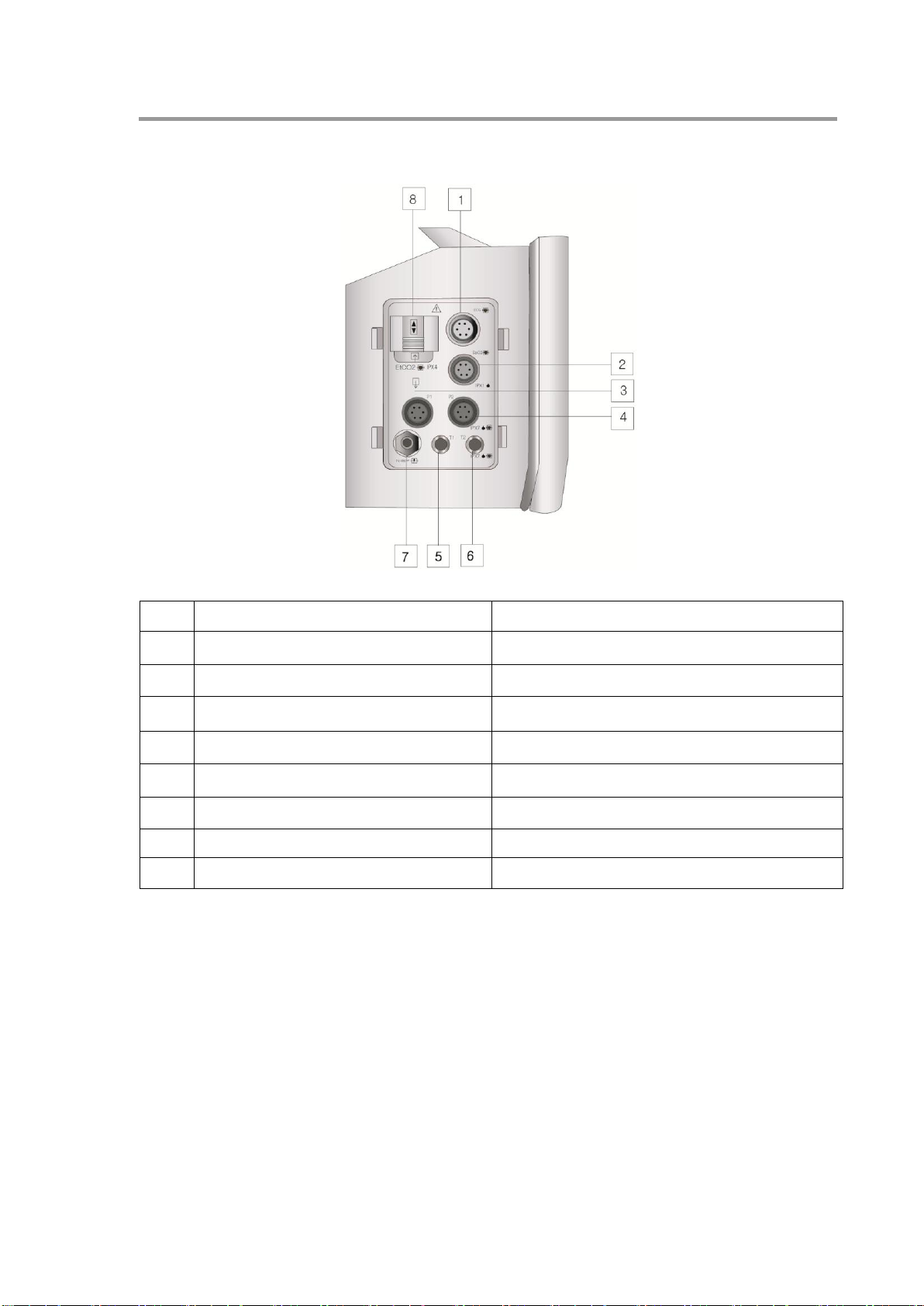
3.3 Components
Front & Operation Panel
▶ Function and Explanation
15
Page 16
VER 1.0
BT-750 Operational Manual
7
Trend Switch
The equipment stores SpO2 and pulse rate for 72 hours in every 1
minute and used to check it
8
Alarm Indicator
When the alarm is on it will show on led
9
Menu Switch
It shows menu on the monitor
10
Speaker
Sound of Alarm and Heart rate.
11
Selection trim knop
It shows entire menu selection.
No.
Item
Function Explanation
1
Printer Power LED
When Printer Power is connected, green light is on
2
Printer Error LED
When Printer is in malfunction, red light is on
3
FEED Switch
Printer Paper selection
4
Printer Cover
Inserting the printer paper and close the cover
[Right Side]
16
Page 17
VER 1.0
BT-750 Operational Manual
No.
Item
Function Explanation
1
ECG/RESP Connection Terminal
It is connector of Measuring ECG/RESP
2
SpO2 Connection Terminal
Connector of SpO2 Sensor
3
IBP 1
Connector of IBP 1
4
IBP 2
Connector of IBP 2
5
TEMP 1 Connection Terminal
Connector of Temp 1 Sensor
6
TEMP 2 Connection Terminal
Connector of Temp 2 Sensor
7
Cuff Connection Terminal
Connector of NIBP Cuff Sensor
8
CO2 Input, Output Connection Terminal
Connector of CO2 Input and Output
[Left Side]
17
Page 18
VER 1.0
BT-750 Operational Manual
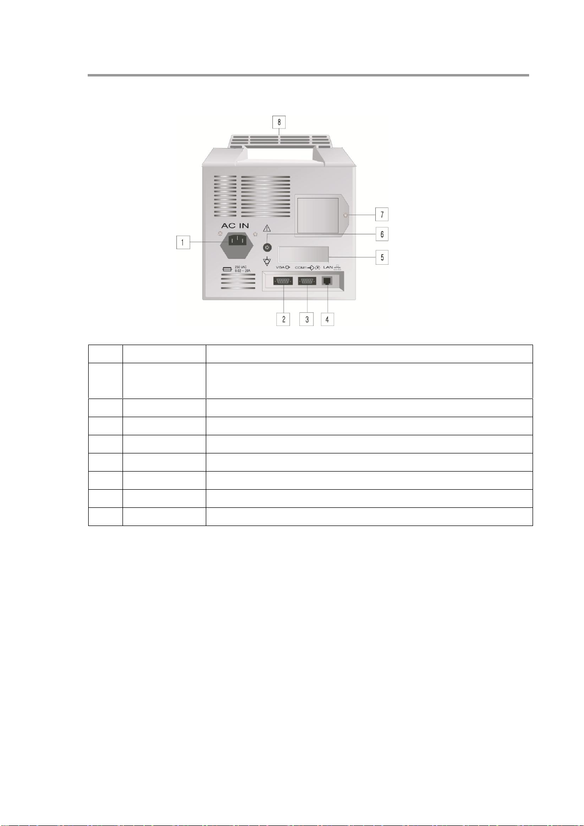
No.
Item
Function Explanation
1
AC Power
Input Port
Port for AC adopter to connect exterior power to the monitor.
2
VGA Port
Reserved
3
RS232 Port
The communication port for connecting monitor and computer.
4
LAN Port
The communication port for connecting monitor and computer (Optional).
5
Label
Display
6
Ground Port
Port of Ground Cable
7
Battery Store
Port of Battery
8
Portable Handle
Handle of carry
[Back Side]
18
Page 19
VER 1.0
BT-750 Operational Manual
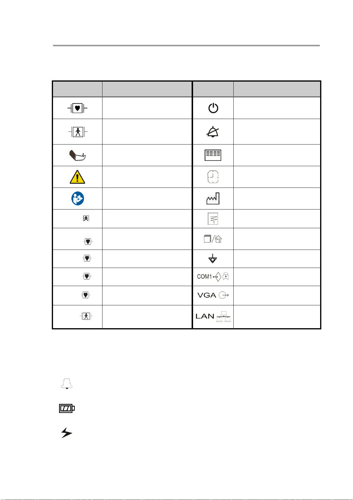
Symbol
Description
Symbol
Description
Type CF Product,
Defibrillation protected
Power Switch
Type BF Product,
Defibrillation protected
Alarm On/Off
Noninvasive Blood
Pressure
Manual Measurement(NIBP)
TREND
Warning Sign
Period of Auto Blood Pressure
Measurement
Refer to instruction
manual/ booklet
Date of Manufacture
T1~2
Measuring Temp.
Start Printing (Printer)
CO2 In/Output
EtCO2
Gas Input/Output
Menu ON/OFF
SPO2
SPO2 Measurement
Ground
P 1~2
Invasive Blood Pressure
RS232 port and nurse call
ECG
Electrocardiograph /
Respiration
Reserved
NIBP
Non Invasive Blood Pressure
Use for Central Monitoring
Indicate that Audio alarm generates
: Display for current charging state of charger. So, make sure of the charging state when
you use only with charger while the AC power is on.
: Indicate that AC power is on
3.4 Description of Product Symbols
3.5 Description of Equipment Symbols
The symbols in the bottom of LCD indicate the present status of BT-750 and us
e bottoms for each function.
19
Page 20
VER 1.0
BT-750 Operational Manual
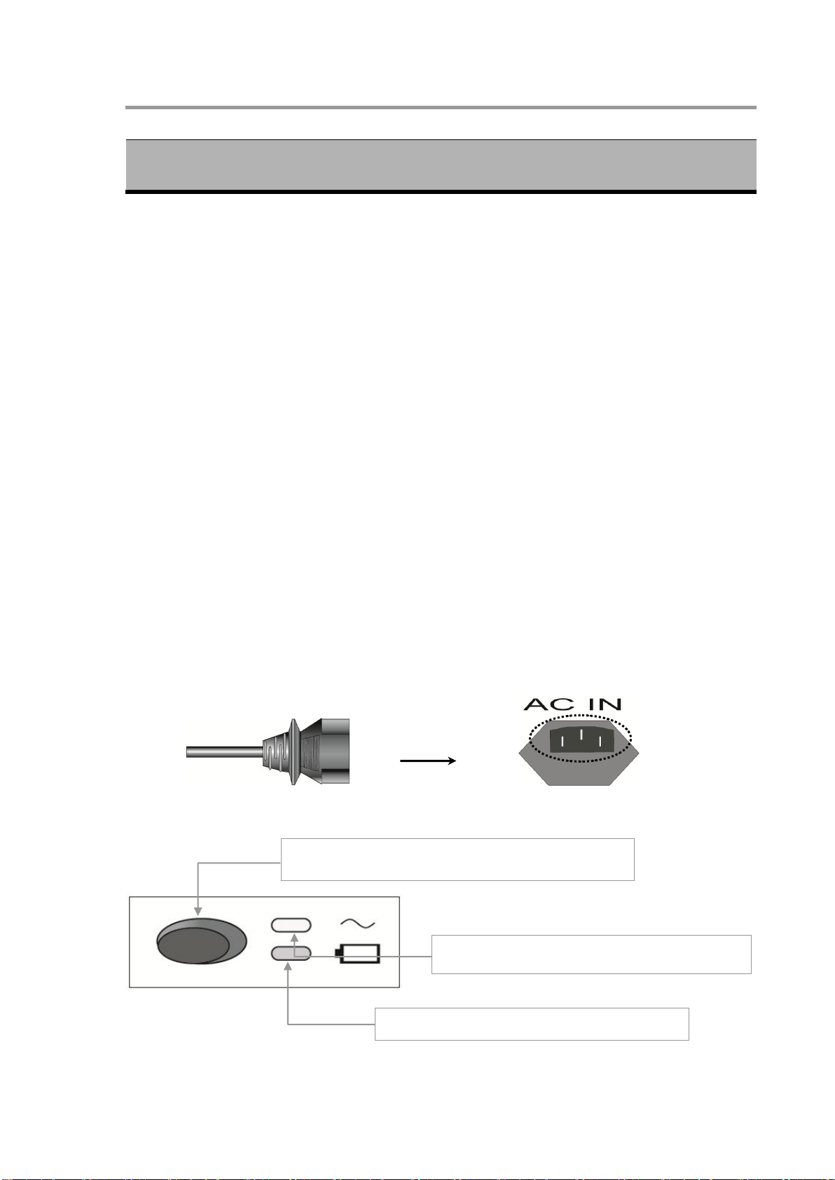
Ch.4 HOW TO SET BT-750
If you continuously press the sub power switch for about 1
seconds, the power is on.
Lamp is on during battery charging. (Orange light)
If you turn on the main power switch, the lamp lights
up while AC adaptor is connected. (Green light)
4.1 Settings
Precautions for Settings
Pay attention when setting BT-750 for the following points
● Use BT-750 under conditions of 10℃∼40℃ of circumstantial temperature and within
80% humidity.
● Check the connection status of the power cord.
● Do not connect multiple cords to the power supply.
Place the main body on a flat area.
If noise occurs, ground the equipment further.
All information is stored in the internal memory, even in the case of power on and off.
Do not use any electric cords generating connecting noise.
Take care since the product can be broken by mechanical shock.
Get rid of dust or inflammable material near the product when setting it up.
4.1.1. How to Use when power is on.
1) Insert AC Adaptor to AC-IN Connector at the rear of BT -750
2) Turn on the On/Off switch at the rear of BT-750
(If the power is in Stand-by, battery starts to charge)
3) If AC lamp of the front side (Green light) is on and you press the power switch
[The front side of the product] [AC Adaptor Ports]
20
Page 21
VER 1.0
BT-750 Operational Manual
NOTE
When battery electronic pressure is in low state, it may cause inaccurately measured
value. Once battery state is low, connect AC Adaptor to the appliance at once.
NOTE
Though AC power cord is connected, charging lamp continuously lights on and after
completing charging, the lamp turns off.
WARNING
For battery replacement, make sure of polarity.
If the battery polarity is placed incorrectly, it may cause fatal problem on equipment.
Contact to Bistos head quarter, when you need battery replacement.
4.1.2 How to Use Battery
In case of sudden blackout or potable purpose, automatically AC Adaptor power transfers to
battery power for continuous use.
How to use
1. Battery charge lamp is off, while battery used.
2. It is durable for approximately 4 hours but depends on battery charged state.
(Full charged time: about 5 hours)
3. Battery charging starts once main power switch of rear side is on after AC Adaptor
connection.
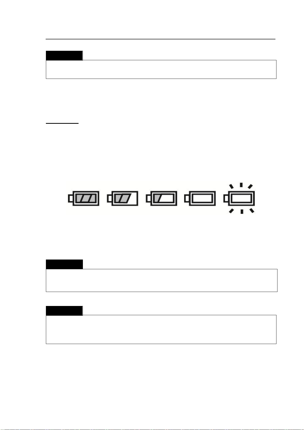
4. Battery charged state displays in 5 steps.
Full charged 70% charged 50% charged 20% charged Discharged
5. When battery is low charged, battery state display on the screen is turned off, beep
sound generates and after about 5 minutes, power is disconnected automatically in
order to protect battery.
If a side of power cord is put to power port of BT-750, power is supplied to the equipment. Make
sure that each cord is connected to input/output terminal correctly. If there is incorrect
connection, it may cause problem.
21
Page 22
VER 1.0
BT-750 Operational Manual
CAUTION
● When the printer door is not perfectly closed, the printing could not be operated or
printed clearly.
● When printing more than 1 minute, the overheating of the printer could be faulty. In
this case, stop the printing at least 3 minutes.
● Please use the right paper and do not use the core adhesive roll. If you use it, it may
occur the malfunction as the printer fails to find the end of the paper.
4.1.3 Connection of Accessories
Connect the accessories for measurement to each mating port of the equipme
nt.
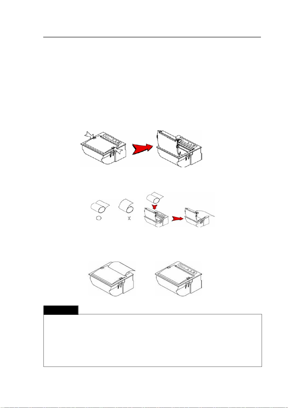
4.1.4 Replacing Roll paper
① Verify if the printer is receiving the data, otherwise it will lose the receiving data.
② Open the printer door by pushing the button at the both side of the printer slightly as
shown the figure below.
③ insert a new paper roll oriented properly like above figure, after verifying the direction of
the paper. Remove the empty paper core and insert a new paper roll oriented properly.
④ Pull the paper out towards you until approximately 2 inches of paper and align the paper.
Close the printer door.
22
Page 23

VER 1.0
BT-750 Operational Manual
CH.5 BT-750 GENERAL OPERATION
5.1 Prior to the Use of BT-750
Make sure of followings prior to check the state of patient.
Check if there is any factor to occur mechanical problem
Review the cosmetic state of probe
Check if there is any error in fiber-optic probe and AC power cable.
Connect the probe to the probe port.
Turn on the monitor and identify that the state of fiber-optic probe is normal and the
cable is connected.
Identify that fiber-optic probe has any problem on connection.
5.2 BT-750 Operation
1) Turn on the power.
2) Adjust the setting with exterior button when change of the value required
3) Figure and waveform are created on LCD screen once ECG probe connected to the
patient.
4) If you apply the SpO2 probe to the patient, data of the patient is displayed on LCD.
5) Apply NIBP cuff to patient. Avoid the arm with SpO2 probe.
6) Apply IBP Kit to patient. Avoid the arm with NIBP cuff.
7) Connect the temperature sensor to the proper position of patient at the type of the
sensor.
8) Apply CO2 kit (optional function)
5.3 BT-750 Operation Notice
Only licensed person must use BT -750.
Read carefully followings prior to use the equipment.
Check the state of battery charging.
Make sure that power and probe are connected correctly to the monitor.
Avoid sudden impact when the machine is transported or each unit is connected.
Read carefully followings prior to use the equipment.
Identify that any error does not occur in entire equipment and patient.
Care for the patient safely and preferentially if any error is found on equipment and take
possible action such as stopping the device operation.
Do not give any impact to the equipment.
23
Page 24

VER 1.0
BT-750 Operational Manual
1
Sweep Speed
13
IBP2 Diastolic
25
Battery Status
2
Status of Filter
14
NIBP Systolic
26
Date and Year Display
3
Detection of Arrhythmia
15
NIBP Diastolic
27
Time Display
4
Heart Rate Measurement
16
NIBP Mean
28
Respiration Alarm Limit
5
Heart Rate Alarm Limit
17
EtCO2 Measurement
29
Respiration Measurement
6
PVC Detect Measurement
18
InCO2 Measurement
30
ECG 1 Wave
7
ST Segment Data
19
Temp. Measurement
31
Wave 2
8
SpO2 Measurement
20
Temperature Alarm Limit
32
Wave 3
9
SpO2 Bar Graph
21
Bed Number
33
Wave 4
10
SpO2 Alarm Limit
22
Patient Mode
34
Wave 5
11
IBP1 Measurement
23
Symbol of Alarm
35
LEAD Display
12
IBP2 Systolic
24
Symbol of AC Power
Keep the probe not to be taken off from the port for exact measurement.
5.4 Turn off the monitor
Turn off the sub-power and verify if the LCD screen turns off
5.5 Basic Screen
▶ Basic screen composition
Press the button in front of BT-750 for power-on.
Display window shows company logo for 2 seconds and is changed to default setting.
▶ Menu
※ When you want to exit from main display or return to basic display by pressing menu button.
24
Page 25

VER 1.0
BT-750 Operational Manual
Order
Operation Method
1
Push the power switch for 1~2 second
2
If you want to change the setting value etc. during use, push the Menu button to change
the setting values per each measurement parameter.
3
When the measurement sensor is connected to the patient, the information on the
patient is displayed as values and waveforms on the LCD screen.
4
Refer to the table below for the details of how to measure each parameter.
5.6 Basic Operation
5.6.1 Simple operation
25
Page 26

VER 1.0
BT-750 Operational Manual
CH.6 MEASUREMENT OF EACH MODULE
ECG Connector
R: Red
L: Yellow
C: White
N: Black
F: Green
R: Red
L: Yellow
F: Green
6.1 Measurement of ECG and Respiration
1) Connect the ECG cable to the ECG connection terminal of the measurement module.
● The process of depolarization and polarization of the myocardium generates electronic
potentials that are sensed by ECG electrodes on the skin surface.
● Changes in the chest impedance resulting from the patient’s respiration is measured and
displayed as a waveform and the values will appear on the screen.
2) Attach the patient’s electrode to the sites shown below.
<Standard 5 Electrode Placement> <Standard 3 Electrode Placement>
26
Page 27

VER 1.0
BT-750 Operational Manual
Lead
Color of electrode
Attaching site
R(RA)
Red (White)
Just below the clavicle (scapula) near the right shoulder
L(LA)
Yellow(Black)
Just below the clavicle (scapula) near the left shoulder
F(LL)
Green(Red)
Lower area of the left side of the abdomen
N(RL)
Black(Green)
Lower area of the right side of the abdomen
C(V)
White(Brown)
Select the candidate lead for measurement among the chest leads
NOTE
● ECG and SpO2 will display synchronized numeric when you stop ECG measurement
while you are measuring ECG SpO2 at the same time.
● The default setting of ECG Lead is ECG1: Lead II, ECG2: Lead III
● In case of using ECG5 Lead cable, you need to set menu 5 Leads at ECG Cable.
● Respiration signals are relatively more sensitive to interference from radiated
electromagnetic signals.
● Do not rely entirely on the equipment.
● Respiration is measured with the ECG and HR etc., using the ECG cable.
● To setup Apnea alarm, push Menu button RESP->APNEA Time
● Priority is EtCO2 measurement when measuring EtCO2.
● Respiration function is very sensitively effected by electromagnetic wave, so it should
avoid from judging the status of patient by numeric value and waveform of respiration.
Name of Arrhythmia
Description
Tachycardia: TAC
Heart rate is over 140bpm for a minute.
Bradycardia: BRD
Heart rate is under 40bpm for a minute.
Premature Ventricular
Contraction: PVC
Abnormal heart rate is over 1.
Ventricular Tachycardia: VTAC
Over 8 PVC is over 140bpm
Asystole: ASY
No electric action of heart.
Ventricular Bigeminy: BGM
After normal heart rate once, two times or more PVC
Ventricular Trigeminy: TGM
After normal heart rate at two times, two times or more PVC
Ventricular: RUN
After normal heart rate at Over 3 (PVC)
Venticule of over 100bpm
Ventricular Fibrillation: VFIB
Very fast ,chaotic heart rate in the lower chambers of
the hearts, resulting from multiple areas of the ventricle
3) Description of Lead IEC (AAMI)
Alarm cases of arrhythmia analysis
27
Page 28

VER 1.0
BT-750 Operational Manual
Is attempting to control the heart’s rhythm.
Multifocal PVCs
Over the last 15 beats two or more premature ventricular beats
Ventricular Couplet (COP)
Abnormal heart rate is more than two times
Missed Beat (MIB)
ECG wave is missed intermediately
R on T PVC
PVC is detected before finishing T wave in the normal ECG
Wave.
Frequent PVCs
PVC generates higher than alarm limit.
CAUTION
Inspection does not carry out the patients with arrhythmia, premature ventricular
contraction or ventricular tachycardia.
SpO2 Connector
6.2 Preparation for SpO2 Measurement
1) Connect SpO2 probe to the probe port.
6.2.1 Setting SpO2 Probe
1) Clean the body part (a finger or a toe) to be inserted to probe for measurement with
alcohol.
2) Set the probe on the finger to measure.(Avoid using it with other medical devices t
o affect blood flow and setting it on the body part in medical treatment)
28
Page 29

VER 1.0
BT-750 Operational Manual
NOTE
When probe is used incorrectly, inaccurate value or waveform can come out as below.
● When the patient uses the other than probes identified in this operation manual.
● Hemoglobin dysfunction
CAUTION
Probe should be treated with attention. Careless use might cause damage to probe. Keep
the probe cable away from acute objects.
When the patient has a high fever or peripheral circulatory failure, the skin and
temperature increases to 2~3 degree.
In case of the patients with cold fingers, SpO2 data is not accurate.
For the patients who have abnormally high oxyhemoglobin or methemoglobin, SpO2 data
is not accurate.
You can not use disposable probe to different patients. For same patient, it is possible to
reuse and remeasure even in different portion. If you want to reuse disposable probe,
disinfection is indispensable.
3) Do not make any motion and be in pause as possible as you can for stable measurement
and fix the probe cable with your fingers or plasters but be careful not to make
interference in blood flow.
4) Make sure that the probe is set on the body part correctly in every 2 or 3 hours. If the
state of your skin is different, change the part to be attached to other side.
29
Page 30

VER 1.0
BT-750 Operational Manual
WARNING
In case of measuring with probe while MRI is in use, the patient may have burns.
To minimize the danger, use non-inductive line, if there exists any danger even with proper
use and remove the connector from the patient.
● Allergic patients should not use disposable probes.
● Make sure that the probes radiate light, faced each other correctly, and the light reaches
to the tissue of a patient. When applying to a newborn baby, use disposable probes
outside of the incubator.
● If used in an incubator, accurate results may not be obtained because the humid air can
have an effect on the outcome. When probe is excessively fixed with tape or used in other
incorrect way, the patient may suffer from injury.
WARNING
If the probe is excessively exposed to medical illumination (especially for xenon light),
bilirubin illumination, fluorescent lamp, IR heating appliances or direct ray of light, this may
cause problem in function. To avoid excessive exposure to the light, use it by the general
operation and be careful that the probe is not exposed to outside ray with opacity. If
outdoor circumstance is under extremely high light, it may generate inaccurate value.
Do not use probe at the body part where intravenous injection or artery catheters are
placed.
Do not use damaged SpO2 probe or optical appliances.
Do not clean with oxygenated water, ultraviolet ray, direct ray of light and steam.
CAUTION
It might fail to measure pulse rate under occasions as follows;
When probe is fastened tightly.
When probe excessively exposes to Medical illumination, bilirubin illumination or sunlight.
In case of being measured on arms or legs in cuffs or bandages
6.3 Setting NIBP
1) Choose the proper cuff for the patient.
2) Connect the cuff hose to cuff.
3) Connect the cuff hose to NIBP font.
4) Put the cuff on the patient
.
30
Page 31

VER 1.0
BT-750 Operational Manual
NOTE
● Use the proper cuff to the patient before measuring blood pressure.
● Inspect excess blood pressure or folding of cuff.
● Avoid the cuff from getting wetness out of any kinds of incidents, and use it after dry
completely.
It is impossible to measure the blood pressure in upper arm, in case that infusion pump or
catheter is inserted in the blood vessel. It may cause damages in the organ around
catheter during the supply of blood pressure.
CAUTION
NIBP hose connector
5) Use the proper cuff to the patient before measuring blood pressure
6.3.1 NIBP measurement
1) It should be measured at the same label of the
patient’s heart in the arms and legs of the pati
ent.
2) The cuff ties part under the position to be measured.
It may cause errors in measurement values.
3) NIBP measurement will be done with button a
nd if you press the button one more time, it stops measurement.
6.4 Temperature Measurement
● Changes in impedance according to the change in the patient’s body temperature is
perceived by the temperature sensor, and then displayed numerically on the screen after a
series of calculations. Measured Temp
31
Page 32

VER 1.0
BT-750 Operational Manual
CAUTION
The temperature sensor should be sterilized before application to another patient.
Temperature Connector
IBP Connector
1) Connect the temperature sensor to the connection terminal of the measurement module
and sensor to patient
6.5 IBP Measurement
Arterial Blood Pressure is the pressure exerted by the blood against the walls of the arterial
vessels. The cardiac cycle consists of a period of relaxation called Diastole, during which
the heart fills with blood, followed by a period of contraction called Systole. While the heart
is contracting and relaxing, the sensor gets the measurement of the pressure.
Setup Connections
1) Connect the interface cable for the transducer to the IBP connector on the monito
r’s front panel. An interface cable for the transducer has to be selected correctly a
s it depends on the each transducer type.
32
Page 33

VER 1.0
BT-750 Operational Manual
NOTE
Note: The monitor is designed to accept signals from BT4812-3 disposable transducer, or
equivalent (pressure range of 0~300 mmHg). Refer to the transducer directions for use for
details.
* This transducer is verified under the connection with to see if protective means is
provided against hazards to patient when used with HF surgical equipment.
2) Set up the patient circuit according to the directions for use of the transducer, mo
nitoring kit.
3) “Hold the backside of the clear cover surrounding the connector, and connect the
converter to the reusable monitor interface.
33
Page 34

VER 1.0
BT-750 Operational Manual
CAUTION
● If a fast flush is performed on the patient, the user should check carefully for the
presence of foam and particulate matter. If a large volume is flushed by force, a short flush
with an increase rate less than 2cc is recommended to avoid central embolism.
● Blood pressure for a liquid infusion line over 300mmHg requires an infusion of more than
3cc per hour. In this case, the pressure must not exceed 775mmHg. A protective function
is set in the flush device, which prevents overpressure of the converter by making the
liquid bypass the device. If a more precise control of fluid volume is required, it is
necessary to connect the infusion pump around the flush device.
4) In a clean environment, open the package to check if all parts are well connected and if
the handle of the “stopcock” is positioned properly. All side ports of the stopcock are
protected by the outlet plugs and may not be removed till the system is full and the foam
has been removed. These outlet plugs should always be replaced with other outlet
plugs. (A pouch is included in the kit.).
5) How to use Flush
Hold both sides of the flush operator and pull upward gently.
Do not revolve the operator and take care not to put the power on one side.
6-1) Twist the sterilized solution bag lightly using a drip chamber spike
6-2) Open the roller clamp and remove the air inside the bag completely by squeezing using
34
Page 35

VER 1.0
BT-750 Operational Manual
CAUTION
The stopcocks of the converter or the outlet should be locked before connecting the doorlock plug
NOTE
<< Priming and Tips >>
● Priming should be done slowly!
- Slow priming will lessen the effort to remove air bubbles afterward.
● Priming using gravity!
- Pressing may result in leakage of liquid or bubbles by forcing the liquid to flow into the
system. If small bubbles flow too slowly inside the system, lift up the supply bag. 1 inch
corresponds to 2 mmHg, and the primed 4-feet line gives a pressure of about 100 mmHg
if it is completely spread out The solution bag should be placed at a higher position than
the converter and the pressing tube, in order for priming using gravity.
an infusion set or a needle inserted into the injection port in the back. By emptying the
back this way, it can prevent air input into the patient’s body.
6-3) Before inputting the solution into the infusion set, push both sides and fill the drip
chamber partially.
6-4) Operate the flush device gently. Since air rises from the bottom, make sure that the
solution is in the bottom at all times.
6-5) Prime the side ports and the plug of the zero point stopcock in the converter using a
door-lock plug.
6-6) Check if bubbles are present in the monitoring system. To check the presence of
invisible bubbles, rap it lightly
6-7) Add pressure to the system up to 300mmHg using C-fuse or the clear cuff. Flush the
system for 2~3 seconds. Check for the presence of air bubbles which may result from
a fast flush. Now, the system is ready for zero point setting and measuring. Place the
stopcock in a 90 degree position to let it off state.
35
Page 36

VER 1.0
BT-750 Operational Manual
CAUTION
● If air foam or bubbles are present inside the system, it may cause significant bias of the
pressure waveform or air embolism.
● Care should be taken not to let air bubbles inside the 3-way outlet stopcock or the
cannula reflush into the patient. To check, confirm if the monitoring line is fully filled with
liquid before connecting the monitoring line and let a small volume of blood flow through
the cannula.
Adjustment of Zero point of the Converter
1) Lock the zero point stopcock (toward OFF) and release the converter according to
the air pressure.
2) Set “Menu”-> “Zero”-> “Yes” in order. If final value is “0”, the measurement starts.
6.6 EtCO2 Measurement (Optional)
Side stream CO2 Gas Measurement
Sidestream CO2 module can be fitted onto IP-3000 Series. Sidestream CO2 provides the
function of EtCO2 and the function to measure respiratory CO2 and respiration numbers
using the small filterline based on a small lumen type filterline. In the Sidestream CO2 type,
the level is measured through the cannula (non-tubing type) attached to the nose or a
sampling line equipped in the respiratory circuit (tubing type).
36
Page 37

VER 1.0
BT-750 Operational Manual
CAUTION
● The maximum sampling rate of the nose tube is 50mL/min. The product should not
applied to patients who may experience respiratory distress by the vacuum flow level.
● To prevent infection of the medical staff by the patient’s respiration sample, the outlet of
BT-750 should be connected to the air elimination system of the hospital.
CAUTION
● The gas inspiring vacuum pressure (negative pressure) of the gas elimination system
should not exceed the pump outlet standard of BT-750, 1mmHg. During zeroing, the air
elimination system should be operating.
● Waste from Microstream and CO2 filter should be treated as fatal biological materials for
the human body
NOTE
Connection of all tubes should be safe, and the nose cannula should be kept away from
the CO2-present area during the self test period
(including the outlet of the ventilator and the respiration of the user)
Range of Respiration Measuring : 0 ~ 150bpm
For the best accuracy, a warm-up of about 2 minutes is required.
NOTE
We do not use specific gas for calibration and manually operate “O” Calibration.
When you adjust “O” calibration, connect it to the transducer and monitor in the air.
The patient may not connect it to the other gas.
Operate “ Menu ZERO YES ” in order
Use it after verifying “O” value at the window screen otherwise the measurement value
would not be correct.
37
Page 38

VER 1.0
BT-750 Operational Manual
CO2 Connector
● How to measure Sidestream CO2
1) Attach the gas/tube to BT-750 Sidestream port and the other side attach to hospital gas
device
2) Respiration numeric is automatically changed when EtCO2 is measured.
3) EtCO2 will be displayed on BT-750 screen after 20 seconds when it detect proper input.
4) EtCO2 waveform and data is displayed. If waveform is not displayed on the screen,
change setting menu “Menu → EtCO
→ EtCO2 → Enable”.
2
5) You can change EtCO2 waveform when you need.
38
Page 39

VER 1.0
BT-750 Operational Manual
CAUTION
The watertrap is disposable and should only be used for a single patient. Do not reuse the
watertrap for another patient.
CAUTION
The cannula is disposable and should only be used for a single patient. Do not reuse the
cannula for another patient.
CAUTION
If oxygen is being delivered while using Sidestream CO2, be sure to use a CO2 Sampling
and O2 Delivery cannula. Using a different type of cannula could obstruct oxygen delivery.
WARNING
Assembly, extension, repair should be carried out by authorized person from BISTOS.
39
Page 40

VER 1.0
BT-750 Operational Manual
CH 7. THE SYSTEM SETUP
Setup Mode
Range of Change
Description
CHANNEL
SETUP
4~5 waveforms. Set up the location at each
waveform. 1~8
Input the number of channels for waveform Set
up the location at each waveform. Set up the
color at each waveform
BED NUMBER
01 ~ 99
Input BED numbers
PATIENT
ADULT/Pediatric/Neonate
Set the age of patient
DATE/ TIME
YEAR : 2000 ~ 2099
MONTH : 1 ~ 12
DATE : 1 ~ 31
HOUR: 0 ~ 23
MINUTE: 0 ~ 59
Date / Time Input
PRINTER
Refer to the setup of printer at 16th chapter
KEY/BEEP
VOLUME
OFF/ 1 ~ 7 (Change at 1 unit )
KEY, Beep Sound setup
ALARM
VOLUME
OFF/ 1 ~ 7 (Change at 1 unit )
Set up the volume of ALARM Sound
NIGNT MODE
ON/OFF
Set up the brightness of the screen.
1) Press the button “ ” to select setup menu.
2) Use the trim knob to go to required location and press the trim knob to set the lo
cation to be modified. Then, selected menu is displayed.
3) Turn to right and left with trim knob and press the trim knob to set up the numeric
Value and save it.
4) Press the button “ ” to return to main display.
You can set up alarm range, volume, date, time of BT-750 in this menu.
7.1 Adjusting the System Setup
40
Page 41

VER 1.0
BT-750 Operational Manual
Setup Mode
Range of Change
Description
DISPLAY
4~5 waveforms
Input the number of channels for waveform
display
Selection of
waveform
Selection of location
1CH : ECG 1(fixed )
2CH : ECG2~CAPNO(6 )
3,4,5CH : PLETH~ CAPNO(5 )
Set up the location at each waveform
Color at each
waveform
8
Set up the color at each waveform.
On operating the service mode such as CHANNEL SET, Date/Time, Printer setup, add
itional active window is opened.
1) Go to the required location with trim knob and select the location, and then the dis
play window becomes active.
2) Set up the values, turning the trim knob to the right / left and save the values afte
r pressing the trim knob.
3) Press “ok” button to revert to the main display window
4) On selection of ‘exit”, it turns to 1st display window.
5) Press “ ” button to revert to the main display window.
1) Go to the required location with trim knob and select the location, then the display
window becomes active.
2) Set up the values, turning the trim knob to the right / left and save the values afte
r pressing the trim knob.
3) Press “RETURN” button to go to 1st display window.
7.2 The modification of system setup (2nd display window)
7.2.1 Selection of CHANNEL
7.2.2 Setup date /time
41
Page 42

VER 1.0
BT-750 Operational Manual
CH.8 ALARM SETUP
1) Press button “ ” to go to adjustment display of alarm
2) Select the menu to change with trim knob and press the trim knob to set the locat
ion to be modified. Then, selected menu is displayed.
3) Turn to right and left with trim knob and press the trim knob to set up the numeric
value and save it.
4) Press “Return” button to go back to 1st display window.
5) Press the button “ ” to return to main display.
8.1 Modification Display Window for 1
(SpO2, Respiration, Temp)
st
Setup
42
Page 43

VER 1.0
BT-750 Operational Manual
1) Press the button “ ” to go to adjustment display
2) Select the menu to change with trim knob and press the trim knob to set the locat
ion to be modified. Then, selected menu is displayed.
3) Activate the display window by pressing trim knob
4) Use the trim knob to go to required location and press the trim knob to set the lo
cation to be modified. Then, selected menu is displayed.
5) Turn to right and left with trim knob and press the trim knob to set up the numeric
value and save it.
6) Press “Return” button to go back to 1st display window.
7) Press the button “ ” to return to main display.
8.2 Modification Display Window for the 2nd Setup
(IBP, NIBP, ECG HR, EtCO2, ST)
43
Page 44

VER 1.0
BT-750 Operational Manual
CH.9 ECG1,ECG2 SETUP
Setup Mode
Range of modification
Description
ECG 3 LEAD
LEAD I, II, III
Set ECG Lead
ECG 5 LEAD
LEAD I, II, III, aVR, aVL, aVF,
V(Chest)
ECG GAIN
1/2,1,2 times
Set the size of ECG wave
WAVE SPEED
6.5, 12.5, 25, 50 mm/sec
Set the velocity of ECG wave
ECG MODE
Monitor/Operation/Diagnosis
Set Analog and Digital filter in ECG wave
LEAD MODE
3 LEAD, 5 LEAD
Set ECG Cable
ARRHYTHMIA
ON/OFF
Set the usage of Arrhythmia analysis
PACEMAKER
ON/OFF
Set the detection of the pacemaker
PVC ALARM
ON/OFF/PVC Alarm Limit
Select whether the alarm generates
or no on detection of PVC .
1) “Press the button “ ” to go to adjustment display
2) Select the menu to change with trim knob and press the trim knob to set the locat
ion to be modified. Then, selected menu is displayed.
3) Turn to right and left with trim knob and press the trim knob to set up the numeric
value and save it.
4) Press “Return” button to go back to 1
st
display window.
5) Press the button “ ” to return to main display.
It sets up the ECG measurement.
9.1 ECG Menu Display
44
Page 45

VER 1.0
BT-750 Operational Manual
HR ALARM
Refer to Ch.8 Alarm setup
ST
SEGMENT
P-R /J + 4~250 ms ,Alarm ON/OFF
Set P-R, J Point
Setup Mode
Range of modification
Description
ECG 3 LEAD
LEAD I, II, III
Set ECG Lead
ECG 5 LEAD
LEAD I, II, III, aVR, aVL, aVF, V(Chest)
ECG GAIN
1/2,1,2 times
Set the size of ECG wave
WAVE SPEED
6.5, 12.5, 25, 50 mm/sec
Set the velocity of ECG wave
1) “Press the button “ ” to go to adjustment display
2) Select the menu to change with trim knob and press the trim knob to set the locat
ion to be modified. Then, selected menu is displayed.
3) Turn to right and left with trim knob and press the trim knob to set up the numeric
value and save it.
4) Press “Return” button to go back to 1st display window.
5) Press the button “ ” to return to main display.
9.2 ECG2 Menu Display
45
Page 46

VER 1.0
BT-750 Operational Manual
1) “Press the button “ ” to go to adjustment display
2) Select the menu to change with trim knob and press the trim knob to set the locat
ion to be modified. Then, selected menu is displayed.
3) Turn to right and left with trim knob and press the trim knob to set up the numeric
value and save it.
4) Press “Return” button to go back to 1
st
display window.
5) Press the button “ ” to return to main display.
● Arrhythmia Analysis can judge problem of Ventricle.
CAUTION
Our ST measurement is only on the basis of ECG 1.
ST Analysis (When ST Segment is on)
● ST Level is measured by horizontal comparison between PR-segment and ST-segment.
User can adjust J point and P-R point at 1~250 4m/sec interval. These measured values
are available only in normal heart rate. In case of abnormal and pacemaker, for example,
Premature Ventricular Contraction, Ventricular Tachycardia etc., it is except ST analysis
because it is possible to cause distortion of ST form.
46
Page 47

VER 1.0
BT-750 Operational Manual
PACEMAKER Detection (When PACEMAKER is on)
● In case Pacemaker is Detection ON, red bar indicate it on the ECG wave form
periodically from input of pacemaker detection
47
Page 48

VER 1.0
BT-750 Operational Manual
CH.10 RESPIRATION MEASUREMENT
Setup Mode
Range of modification
Description
WAVE SPEED
6.5/12.5/25 mm/s
Set Wave Speed
RESP LEAD
RA-LL/RA-LA
Set one of two
RESP GAIN
1, 2 OHM
Set the size of RESP waveform
APNEA ALARM
ON/OFF
Set alarm for apnea
APNEA TIME [SEC]
0~200 Sec.
Set detection of Apnea
RESP ALARM
Refer to CH.8 Alarm Setup
1) Press the button “ ” to go to adjustment display.
2) Select the menu to change with trim knob and press the trim knob to set the loc
ation to be modified. Then, selected menu is displayed.
3) Turn to right and left with trim knob and press the trim knob to set up the numeri
c value and save it.
4) Press “Return” button to go back to 1st display window.
5) Press the button “ ” to return to main display.
It sets up How to Measure Respiration
10.1 Respiration Menu Display
The range of respiration setup
48
Page 49

VER 1.0
BT-750 Operational Manual
CH.11 SETUP FOR SpO2 MEASUREMENT
Setup Mode
Range of change
Description
Wave Speed
6.5, 12.5, 25, 50 mm/sec
SpO2 Waveform Speed
SpO2 PR
Pulse rate ON/OFF
Display Pulse Rate ON/OFF
SpO2 Alarm
Refer to Ch.8 Alarm setup
11.1 SpO2 Menu Display
1) Press the button “ ” to go to adjustment display.
2) Select the menu to change with trim knob and press the trim knob to set the lo
cation to be modified. Then, selected menu is displayed.
3) Turn to right and left with trim knob and press the trim knob to set up the num
eric value and save it.
4) Press “Return” button to go back to 1st display window.
5) Press the button “ ” to return to main display.
Range of SpO2 setup
49
Page 50

VER 1.0
BT-750 Operational Manual
CH.12 NIBP SETUP
Setup Mode
Range of change
Description
NIBP Mode
AUTO , Manual, Stat
Setup Automatic / Manual / Stat measurement
Interval
1, 3, 5, 10, 30, 60, 90, 120, 240 min
Set the interval of the automatic NIBP
measurement time
NIBP Unit
mmHg, kPa
Set the unit of blood pressure
NIBP Alarm
Refer to Ch. 8 Alarm Setup
NOTE
When patient needs to use Stat Mode, it must press button at the
bottom of the monitor after adjustment of Stat Mode..
12.1 NIBP Menu Display
1) Press the button “ ” to go to adjustment display.
2) Select the menu to change with trim knob and press the trim knob to set the location to
be modified. Then, selected menu is displayed.
3) Turn to right and left with trim knob and press the trim knob to set up the numeric
value and save it..
4) Press “Return” button to go back to 1
st
display window.
5) Press the button “ ” to return to main display
Range of NIBP Setup
*STST Mode is Setup mode to measure the blood pressure for 5 minutes continuously .
50
Page 51

VER 1.0
BT-750 Operational Manual
CH.13 IBP SETUP
Label
Site
Scale
ABP
Arterial blood pressure
0~200 mmHg
P1
Standard labels
0~200 mmHg
Label
Site
Scale
P2
Standard labels
0~25 mmHg
CVP
Central venous pressure
0~25 mmHg
PAP
Pulmonary arterial pressure
0~50 mmHg
LAP
Left arterial pressure
0~25 mmHg
13.1 IBP Menu Display
1) Press the button “ ” to go to adjustment display.
2) Select the menu to change with trim knob and press the trim knob to set the location
to be modified. Then, selected menu is displayed.
3) Turn to right and left with trim knob and press the trim knob to set up the numeric
value and save it.
4) Press “Return” button to go back to 1
st
display window.
5) Press the button “ ” to return to main display.
Table for labels according to the site of measurement for BP1
Table for labels according to the site of measurement for BP21
51
Page 52

VER 1.0
BT-750 Operational Manual
Setup Mode
Range of change
Description
WAVE SPEED
6.25, 12.5, 25,50 mm/sec
Set the speed of IBP waveform
BP1 LABEL
P1 , ABP
Set the level according to the measurement site of BP.
Change the alarm setting range according to level.
BP1 SCALE
50,100,200,300 mmHg
Set the display of BP1 wave scale
BP1 ZERO
YES/NO
Adjust the zero point of the transducer
BP1 ALARM
Refer to Ch.8 Alarm Setup
BP2 LABEL
P2,CVP,PAP,LAP
Set the level according to the measurement site of BP.
Change the alarm setting range according to level.
BP2 SCALE
25,50,100,200,300 mmHg
Set the display of BP2 wave scale
BP2 ZERO
YES/NO
Adjust the zero point of the transducer
BP2 ALARM
Refer to Ch.8 Alarm Setup
IBP
Enable / DISABLE
Select the IBP display
IBP measurement range
IBP inactive display window (Show the unified NIBP display window)
52
Page 53

VER 1.0
BT-750 Operational Manual
CH.14 TEMPERATURE SETUP
Setup Mode
Range of change
Description
Temp Unit
℃, ℉
Set the unit of temperature
Temp 1 Alarm
Refer to Ch.8 Alarm Setup
Temp 2 Alarm
It sets up temperature measurement
14.1 Temperature Setup display
1) Press the button “ ” to go to adjustment display.
2) Select the menu to change with trim knob and press the trim knob to set the location to
be modified. Then, selected menu is displayed.
3) Turn to right and left with trim knob and press the trim knob to set up the numeric
value and save it.
4) Press “Return” button to go back to 1
st
display window.
5) Press the button “ ” to return to main display.
Temperature Menu Setup Range
53
Page 54

VER 1.0
BT-750 Operational Manual
CH.15 EtCO2 SETUP
Setup Mode
Range of Change
Description
WAVE SPEED
6.25, 12.5, 25 mm/sec
Set the speed of EtCO2 waveform
UNIT
mmHg, kPa, %
Set the unit of EtCO2 measurement
SCALE
~12,~25, ~50, ~70, ~100,~150 mmHg
Set the WAVE SCALE
ZERO
YES / NO
Adjust the zero point of the
transducer
AVERAGE
1 BREATH, 10, 20 Sec
Set DATA average time DATA
Gas COMP
NON,O2/N2O, N2O, O2
Set the Gas type
EtCO2
Enable / DISABLE
Set ON/OFF of EtCO2 module
ALARM
Refer to Ch.8 Alarm Setup
1) Press the button “ ” to go to adjustment display.
2) Select the menu to change with trim knob and press the trim knob to set the loc
ation to be modified. Then, selected menu is displayed.
3) Turn to right and left with trim knob and press the trim knob to set up the numeri
c value and save it.
4) Press “Return” button to go back to 1
st
display window.
5) Press the button “ ” to return to main display.
15.1 CO2 Setup Display
● Setup range of EtCO2
54
Page 55

VER 1.0
BT-750 Operational Manual
CH. 16 TREND SETUP
Mode
Description
SCAN
Select the data of current page by adjusting Trim Knob.
PAGE
Could see 1~17 pages by adjusting Trim Knob
Show the data of 174 cases each page.
-- SEC
Store interval data by selected interval second.
Store the data of approximately 2960 cases
1) Press the button “ ”to convert to Trend display window.
2) Adjust the tram knob and select SCAN Then, selected bar becomes active. Adjust
the bar to the required location with tram knob.
3) Select the PAGE with tram knob, to turn over display window.
4) Press the button “ ” to return to main display.
NOTE
Up to the selection of Second, it could store minimum 8 hours to maximum 72 hours
trend data.
16.1 Trend display
55
Page 56

VER 1.0
BT-750 Operational Manual
CH.17 PRINTER SETUP
Setup Mode
Range of change
Description
WAVE
ECG 1+ ECG 2
ECG 1+ PLETH
ECG 1+ RESP
ECG 1+ IBP 1
ECG 1+ IBP 2
ECG 1+ CAPNO
Select the waveform to print out
PRINT SPEED
25/50 mm/sec
Select speed of printer
PRINT ALARM
ON / OFF
ON: Print out in case of over alarm limit automatically.
1) Press the menu button “ ” to go to Setup Printer Setup.
2) Select the menu to change with trim knob and press the trim knob to set the loc
ation
to be modified. Then, selected menu is displayed.
3) Press the trim knob to make the display window active in second time.
4) Go to the required location with tramp knob and press the tram knob to set the
Location to be modified, then the setting location becomes active.
5) Turn to right and left with trim knob and press the trim knob to set up the numeri
c value and save it.
6) Press “Return” button to go back to 1
st
display window.
7) Press the button “ ” to return to main display.
17.1 Printer Menu Display
Select the each Printer Mode using same method.
56
Page 57

VER 1.0
BT-750 Operational Manual
OFF: manual printing
CH.18 DEFAULT SETUP
Parameter
Item Name
Adult
Pediatric
Neonate
ECG
LEAD
1st CH
LEAD II
LEAD II
LEAD II
2st CH
LEAD III
LEAD III
LEAD III
GAIN
1st CH
x 1
x 1
x 1
2st CH
SPEED
1st CH
25 mm/sec
25 mm/sec
25 mm/sec
2st CH
CONFIG
MODE
MONITOR
MONITOR
MONITOR
LEAD
3 LEAD
3 LEAD
3 LEAD
ARRHYTHMIA
OFF
OFF
OFF
PACEMAKER
OFF
OFF
OFF
HR ALARM
ON
ON
ON
ST
P-R
96mS
96mS
96mS
J
92mS
92mS
92mS
ST
ALARM
HIGH Limit
+3.6mm
+3.6mm
+3.6mm
LOW Limit
−3.6mm
−3.6mm
−3.6mm
ALARM
HIGH Limit
120 bpm
160 bpm
200 bpm
LOW Limit
50 bpm
75 bpm
100 bpm
SpO2
WAVE SPEED
25 mm/sec
25 mm/sec
25 mm/sec
PR
ON
ON
ON
ALARM
ALARM
ON
ON
ON
HIGH Limit
OFF
OFF
OFF
LOW Limit
90 %
90 %
90 %
TEMP
UNIT
℃ / ℉
℃
℃
℃
ALARM
1st CH
ON
ON
ON
2st CH
ON
ON
ON
1st
HIGH
39.0℃/102.2℉
39.0℃/102.2℉
39.0℃/102.2℉
2st
LOW
36.0℃/96.8℉
36.0℃/96.8℉
36.0℃/96.8℉
1st
HIGH
39.0℃/102.2℉
39.0℃/102.2℉
39.0℃/102.2℉
2st
LOW
36.0℃/96.8℉
36.0℃/96.8℉
36.0℃/96.8℉
BT-750 have factory setting as below;
18.1 Default Setup
57
Page 58

VER 1.0
BT-750 Operational Manual
RESP
SPEED
12.5 mm/sec
12.5 mm/sec
12.5 mm/sec
LEAD
RA-LL
RA-LL
RA-LL
GAIN
x 2
x 2
x 2
APNEA ALARM
OFF
OFF
OFF
APNES TIME[SEC]
30 sec
30 sec
30 sec
ALARM
ON / OFF
OFF
OFF
OFF
HIGH
30rpm
30rpm
100 rpm
LOW
8rpm
8rpm
30 rpm
NIBP
MODE
MANUAL
MANUAL
MANUAL
INTERVAL
60 MIN
60 MIN
60 MIN
UNIT
mmHg
mmHg
mmHg
ALARM
ON / OFF
ON
ON
ON
HIGH
160/90(110)mmHg
21.3/12.0(14.7)kPa
120/70(90)mmHg
16.0/9.3(12.0)kPa
90/40(70)mmHg
12.0/8.0(9.3)kPa
LOW
90/50(60)mmHg
12.0/6.7(8.0)kPa
70/40(50)mmHg
9.3/5.3(6.7)kPa
60/20(30)mmHg
5.3/2.7(4.0)kPa
EtCO2
WAVE SPEED
12.5 mm/sec
12.5 mm/sec
12.5 mm/sec
UNIT
mmHg
mmHg
mmHg
SCALE
~25mmHg
~25mmHg
~25mmHg
AVERAGE
10 SEC
10 SEC
10 SEC
GAS COM.
NON
NON
NON
DISABLE/ENABLE
DISABLE
DISABLE
DISABLE
ALARM
ON / OFF
OFF
OFF
OFF
EtCO2
HIGH
80mmHg
10.7 kPa
10.5%
80mmHg
10.7 kPa
10.5%
80mmHg
10.7 kPa
10.5%
LOW
00mmHg
0 kPa
0%
00mmHg
0 kPa
0%
00mmHg
0 kPa
0%
INCO2
HIGH
20mmHg
2.7 kPa
2.6%
20mmHg
2.7 kPa
2.6%
20mmHg
2.7 kPa
2.6%
LOW
00mmHg
0 kPa
0%
00mmHg
0 kPa
0%
00mmHg
0 kPa
0%
IBP
SPEED
1st CH
25 mm/sec
25 mm/sec
25 mm/sec
2st CH
25 mm/sec
25 mm/sec
25 mm/sec
LABEL
1st CH
P1
P1
P1
58
Page 59

VER 1.0
BT-750 Operational Manual
2st CH
P2
P2
P2
SCALE
1st CH
~200mmHg
~200mmHg
~200mmHg
2st CH
-50mmHg
-50mmHg
50mmHg
ALARM
1st CH
0N
0N
0N
2st CH
0N
0N
0N
1st CH
HIGH
160/90(110)mmHg
21.3/12.0(14.7)kPa
120/70(90)mmHg
16.0/9.3(12.0)kPa
90/40(70)mmHg
12.0/8.0(9.3)kPa
LOW
90/50(60)mmHg
12.0/6.7(8.0)kPa
70/40(50)mmHg
9.3/5.3(12.0)kPa
60/20(30)mmHg
5.3/2.7(4.0)kPa
2st CH
HIGH
160/90(110)mmHg
21.3/12.0(14.7)kPa
120/70(90)mmHg
16.0/9.3(12.0) kPa
90/40(70)mmHg
12.0/8.0(9.3)kPa
LOW
90/50(60)mmHg
12.0/6.7(8.0)kPa
70/40(50)mmHg
9.3/5.3(6.7) kPa
60/20(30)mmHg
5.3/2.7(4.0) kPa
IBP
DISABLE/ENABLE
ENABLE
ENABLE
ENABLE
The other setup values
SETUP
CHANNEL
SETUP
DISPLAY
5-CH WAVE
Wave
ECG1, PLETH, BP1, BP2, PR
BED NUMBER
01
PATIENT
ADULT
KEY/BEEP VOLUME
02
ALARM VOLUME
02
NIGHT MODE
OFF
59
Page 60

VER 1.0
BT-750 Operational Manual
CH.19 ALARM
Alarm type
Tone Pitch
Beep Rate
IEC60601-1‐8
IEC60601-1‐8
High Level Alarm
~976 Hz
10 beeps in 15 sec
Medium Level Alarm
~697 Hz
3 beeps in 15 sec
Low Level Alarm
~488 Hz
1 beeps in 30 sec
Function
Message
Description
SpO2
STAND BY
Probe is connected but the finger is out of probe.
NOTE
When you use battery and alarm generates , the alarm volume is small
BT-750 offers Alarm function to user. User should have full knowledge about this chap
ter and take right action on alarming. BT -750 provides alarm service in two ways. On
e is audio Alarm and the other is alarm message.
19.1 AUDIO ALARM
The high level alarm beeps 5 times and it beeps 5 times. The high level alarm has a specific
rhythm that meets international standard. The medium level alarm beeps 3 times at 15
second intervals. Low-level alarm beeps to inform the occurrence of following state. Low
level alarm beeps once at 30 seconds
● High Level Alarm
It operates only when the value is extremely in abnormal state. For example, if pulse rate indicates 0,
high level alarm generates regardless of alarm limit.
● Medium Level Alarm
It operates only when the value is beyond alarm limit.
● Low level Alarm
It beeps when abnormal result brings up or there is anything that the user needs to be
informed.
● Visual alarm
To help you detect the cause of an alarm, the numeric values of the relevant items keep
blinking.
19.2 Alarm icon
The alarm icon appears on the information window of the lower screen..
60
Page 61

VER 1.0
BT-750 Operational Manual
CHECK PROBE
Finger probe is out of probes
ECG
CHECK
SENSOR
Sensor is out of body or cable is out of the monitor
IBP
Temperature
EtCO2
NIBP
CUFF HOSE
Failure of pressurization for definite time
NO PULSE
Fail to detect pulse rate
OVER PRES
Error in measurement values for moving
READ FAIL
Blood pressure is over 300 mmHg
ALARM
LOW
Refer to Alarm Generating Chart
MIDIULM
HIGH
Message
Generating Cause
HIGH
When pulse rate is not detected (“0” BPM)
MEDIUN
Out of numeric value
LOW
1. SpO2 PROBE ERROR
2. LOW BATTERY
3. Fail to measure NIBP or Over Pressure
4. Lead Fault during ECG measurement
5. Finger is out of SpO2 probe during SpO2 measurement
6. Fault during Temp measurement
7. Fault during IBP measurement
8. PACEMAKER Detect
NO
DISPLAY
SOUND
REMARK
1 Normal alarming
Default
2
Holding alarm for 60 sec.
Pressing alarm button once
3 Alarm sound off for 120 sec.
Pressing alarm button twice
4
Alarm off
Refer to the chapter 14
[Alarm Generating Chart]
Alarming display is illuminated in every alarming. It is changed to the below chart,
in every moment pressing alarming button ,when alarm generates.
Please press the alarm button ‘once’ in low level alarm to cancel it.
61
Page 62

VER 1.0
BT-750 Operational Manual
CH. 20 POWER
CAUTION
Messages generate and indicators are illuminated, regardless of alarming or not
CAUTION
● Noise may occur in waveform, while using AC power. In this case, ground the product.
● It may occur the fatal damage to the product, while connecting AC power with wet
hand.
CAUTION
While the monitor is working, battery charging lamp is on. When sub-power switch is
turned off and battery charging completes, lamp is out.
19.3 Setting Up Alarm Hold
After alarm generates, user can hold audio alarm and set up the time to 1min/2min/normal.
If each event which generates alarming within setting time is not cancelled, audio alarm will
generate again.
BT-750 can use both of AC/DC powers. Battery as well as AC power can be used for potable
purpose and it is possible to use charged battery on AC power-on.
20.1 AC Power
If AC power is connected to the monitor and turn on the AC power switch, Green LED is on
to indicate Power-on. It is automatically converted to a recharging mode.
20.2 Battery charge
If AC power is disconnected, power is supplied thru battery. When battery power is not
sufficient, you should charge it by connecting AC adaptor.
● Recharging time: More than 5 hours.
● Duration time: Under 3 hours.
● In case of discharged battery.
62
Page 63

VER 1.0
BT-750 Operational Manual
Temperature
Shelf Life
21 °C to 30 °C
12 months
31 °C to 40 °C
6 months
Rate of charge/discharge
Times
100 % charge/discharge
100 times
50 % charge/discharge
200 times
30 % charge/discharge
500 times
CAUTION
Dispose of the battery into a proper place for the protection of environment.
Keep the battery dry.
CAUTION
Do not disassemble or reorganize the battery.
20.3 Battery type
BT-750 uses Lithium-lon battery.
The table below shows the battery life while not in use.
20.3.1 Battery Replacement
Replace the battery with a same type of battery[The product supplied by BISTOS]
Type : Rechargeable Lithium-Ion Battery
Company : LG Chem
20.3.2 Battery Replacement Period
If you start to use the system in battery-operated mode, it is necessary to keep it in use
without stop, meanwhile, in care of discharge, the battery life will be shortened. You may
refer the table below for battery replacement period.
You should replace the battery when the duration time gets shorten or charging is not done
properly. When the monitor is connected to the power, battery is charged automatically.
You can not use the battery, with separated from the monitor.
20.3.3 Battery Storage Maintenance
Storage temperature (Humidity: 20 ~ 85 %RH without condensation)
-20 ~ 20℃ : less than 1 year
-20 ~ 45℃ : less than 3 months
-20 ~ 60℃ : less than 1 month
20.3.4 How to replace Battery
You must contact the head quarter or agent of BISTOS.
63
Page 64

VER 1.0
BT-750 Operational Manual
CH. 21 EXTERNAL INTERFACE
Pin No.
Signal
1
RS232 level nurse call
2
RS232 RX
3
RS232 TX
4
not used (open)
5
RS232 ground
6
not used (open)
7
not used (open)
8
not used (open)
9
Nurse call common
The monitor provides external connectors on the rear side panel to support communication
with external equipment and functions such as a nurse call, PC connection.
The description of RS-232 pin arrangement
* LAN is optional and VGA is reserved.
64
Page 65

VER 1.0
BT-750 Operational Manual
CH. 22 TROUBLE SHOOTING GUIDE
Problem
Sign
Solution
Cannot turn
the Power on
Check whether AC power
line is plugged in.
Faulty power switch
☞ Connect to AC power properly.
☞ Contact our customer service center or
repair center.
Cannot produce
the proper waveform
Unstable connection.
☞ Check the connections of the power,
connectors, and the accessories.
Problem
Solution
The message“ LEAD
FAULT” is displayed.
1. Check the ECG cable and ensure that the gel in the electrode is not dry.
2. Try using another ECG cable.
The ECG waveform
Is not displayed.
1. Check if the cable connection is stable.
2. Check if the ECG cable is damaged.
Severe noise on the
waveform.
1. Check if the electrode attached to the patient is stable.
2. Check if the disposal electrode is one provided by the company.
(Noise may occur according to the kind of electrode.)
Problem
Cause
Solution
Error display
by ray interference
Errors generated by excessive ray
outside.
Cover the probes
with opaque substances
Error by
electromagnetic wave.
Power cable or connector is placed
closely with probes.
Keep probes away from power cable
and connector.
Error display
Use of improper probes or clinical
problem Misplaced probes or patient
moving.
Probes do not attach to the patient
Use of proper probes. Place probes
in right location Fix probe and cable
with tape and use new probes as
required.
Output failure
of SpO2 value
Change of arterial blood capacity by
shock
Apply to other body part
This chapter explains the solutions to simple problems. One might feel difficulty to use
while operating the monitor. At this moment, before regarding it as breakdown, check
the following points.
▣ Problem of ECG/Respiration measurement
▣ Problems in SpO2 Measurement
65
Page 66

VER 1.0
BT-750 Operational Manual
SpO2 waveform
displays in small or
flat shape.
Fingers in cold temperature or
improper probe use , setup error for
waveform size
Apply to other body part or check if it
is used in proper way and waveform
size is set up correctly.
Problem
Solution
NIBP measurement is not done
properly
- Reset the power
- Contact our customer service center or repair center.
NIBP measurement is failed
- Make sure if the patient uses proper cuff.
- Make sure if the posture of the patient and the portion to be
measured are suitable.
- Contact our customer service center or the repair center.
Problem
Solution
Blood pressure measurement
is unstable.
Pour out the contents of the tube carefully and remove the bubble,
then shorten the tubing length.
Severe noise or bias in the
waveform.
Do not shake or touch the connection area of the IBP sensor.
Problem
Solution
FILTERLINE NOT
CONNECTION
The filter line is not connected to the main body. Connect filter line
disconnected the filter line.
EtCO2 and InCO2 are Blank
Contact the agency.
EtCO2 waveform and
numeric are not
displayed
Check if the sampling line and filter is obstructed, and clean it up if
possible. It should be changed if necessary. To remove this
message, disintegrate the filter line and then reconnect it.
Problem
Solution
No printing.
Check if the message “PRINTER” is displayed on the screen.
Check if the power LED lights up on the printer.
Check if the paper is set normally.
Check if the printer door is closed.
Noise during printing.
Check if the roller is contaminated with foreign materials or if the
gear is out of position.
Check if the problem is due to a paper jam (change the paper)
▣ NIBP measurement
▣ IBP measurement
▣ EtCO2 measurement
▣ Problems in the Printer measurement (Optional)
Please contact our customer service center or repair center if there is any defects or inquiry.
66
Page 67

VER 1.0
BT-750 Operational Manual
CH.23 BT-750 (PATIENT MONITOR) SPECIFICATIONS
BT-750
MAIN BODY
Specification
Power:
Voltage:
Frequency:
Power Consumption:
100240 VAC
50/60 Hz
100 VAmax
LCD
Dimension:
Resolution:
10.4” Color Wide TFT LCD
800 x 480
ECG Module
Lead:
HR (Heart Rate)
Measurement Range
Accuracy
Sweep speed
Lead-off Detection
CMRR
Voltage range
Signal Width
3/5 electrodes, detected automatically
I, II, III, aVR, aVL, aVF, V (Chest Lead)
20 bpm to 300 bpm
±3 bpm or ±5 % whichever is greater
6.25 mm/s, 12.5 mm/s, 25 mm/s, 50 mm/s
Detected and displayed
> 90 dB Minimum at 50 or 60 Hz
±0.5 mV to ±5 mV
40 ms to 120 ms(Q to S)
SpO2 Module
Measurement range:
Accuracy:
Display Sweep Speed
Resolution
Pulse rate
Accuracy
1 ~ 100 %
Adult
71 % ~ 100 % : 2 digits
50 % ~ 70 % : 3 digits
Neonate
71 % ~ 100 % : 2 digits
50 % ~ 70 % : 2 digits
6.25 mm/s, 12.5 mm/s, 25 mm/s, 50 mm/s
1 %
20~250 bpm
2 bpm in whole detectable range
67
Page 68

VER 1.0
BT-750 Operational Manual
Low Perfusion
0.1% up to
NIBP Module
Cuff Inflation Rate
Auto mode Repetition
Measurement Time (Typical at HR >
60bpm)
Accuracy
Maximum Standard Deviation
Maximum Mean Error
Adult / pediatric Mode
Measurement Ranges
Systolic
Diastolic
MAP
Neonate Mode
Measurement Ranges
Systolic
Diastolic
MAP
Overpressure Alarm Limit value
Adult
Neonate
3 to 18 seconds
1, 3, 5, 10, 30, 60, 90, 120, 240 minutes
25 seconds
8 mmHg
±5 mmHg
50 ~ 255 mmHg
30 ~ 220 mmHg
40 ~ 235 mmHg
30 ~130 mmHg
20 ~ 100 mmHg
25 ~ 120 mmHg
300 mmHg(40kPa)
150 mmHg(20kPa)
Respiration rate
Method Type
Range
Lead
Accuracy
Display Sweep Speed
Lead off Condition
Trans-thoracic impedance
0 to 150 breaths/min
Lead 2 only RA to LA
±1 breaths/min
6.25 mm/s, 12.5 mm/s, 25.0 mm/s
Detected and displayed
Temperature
Method Type
Compatible with
Parameter displayed
Range
Display Accuracy
Thermistor
YSI Series 400 Temperature Probes
TEMP1, TEMP2
10℃to 45℃ [50℉ to 113℉]
±0.1℃(25℃ to 45℃) or ±0.2℉ [77℉ to 113℉]
±0.2℃(10℃ to less than 25℃) or ±0.4℉ [50 ℉
68
Page 69

VER 1.0
BT-750 Operational Manual
to less than 77℉]
IBP
Channel
Method Type
Pulse rate range
Pulse rate accuracy
Pressure Measurement range
Parameter Displayed
Input Impedance
Transducer Driving Voltage
Transducer input Sensitivity
Transducer Volume Displacement
Zero Calibration Range
Zero Calibration Accuracy
Frequency Characteristics
Pressure Display Accuracy
Scale
Display Sweep Speed
2 Channel
Pressure Transducer Method
20 to 250 bpm
±1 % or ±1 bpm
0 to +300 mmHg
P1, ABP
P2, CVP, PAP, LAP
More than 1 M Ω
DC 5 V
5 ㎶/V/mmHg
0.1 ㎣/mmHg
±100 mmHg
Less than ±1 mmHg
DC to 25 ㎐
Monitor: Less than ±3 mmHg
P1 0~50, 0~100, 0~200, 0~300,
P2 0~25, 0~50, 0~100, 0~200, 0~300
6.25 mm/s, 12.5 mm/s, 25 mm/s, 50 mm/s
Capnography
CO2
Parameter Displayed
Method type
Rise Time
Warm Up Time
Sweep Speed
CO2 Measurement range
CO2 Accuracy
EtCO2, InCO2
Non-dispersive infrared
Single beam optics, dual Wavelength,
no moving parts
less than 60ms
2 minutes maximum
6.25 mm/s, 12.5 mm/sec, 25.0 mm/sec
0 to 150 mmHg
0 to 20 kPa
0 to 19.7 %
0 to 40mmHg ±2mmHg
41 to 70mmHg ±5% of reading
71 to 100mmHg ±8% of reading
101 to 150mmHg ±10% of reading
69
Page 70

VER 1.0
BT-750 Operational Manual
Respiratory rate range
Respiratory rate accuracy
Scale
0 to 150 breath/min
±1 breath
0~12 mmHg
0~25 mmHg
0~50 mmHg
0~700 mmHg
0~100 mmHg
0~150 mmHg
Printer
Resolution:
Total number of dots:
Paper Width:
Printing Speed:
Weight:
Dimensions:
8 dots/mm
203 dots/mm
48 mm
50 mm/s
160 g
80 x 75 x 40 (mm)
Dimensions:
257 x 236 x 161 (mm)
Weights:
3 kg(including battery)
Environmental conditions:
Operation:
Temperature:
Relative humidity:
Atmospheric pressure:
Storage:
Temperature:
Relative humidity
Atmospheric pressure:
5℃~40℃( 41℉-104℉)
80 %RH max @40℃(104℉ non-condensing)
500~1060 hPa
-20 C~80 C( -4℉~176℉)
90 % RH max @50℃(122℉)`
500~1060 hPa
ACCESSORY
Specification
ECG / Respiration Electrode & Cable
SpO2 Probe
5 electrodes & 3/5 Cable
Finger type reusable sensor.
Adult (STD.Accessory)
Child/Neonatal(optional)
Disposable sensor (optional)
Adult/Neonate/Pediatric/Infant
Accuracy : 2 %
Shape : Clip type
70
Page 71

VER 1.0
BT-750 Operational Manual
Cuff
Temperature probe
IBP kit
CO2 kit(option)
Battery
Charging time :
Capacity :
Led specification : Red & infrared, nominal
Photodiode
-Active area : 5 mm
2
-Responsibility : 0.18 Min
Reusable cuff Adult cuff(STD.Accessory)
Reusable cuff Big Adult/Child/ Pediatric/ infant
cuff( optional)
YSI 400 Series (YSI Inc.)
Temperature range : 0°C - 60°C
Accuracy : ±0.2°C from 0 to 60°C,
±0.1°C from 32 to 42°C
Disposable Pressure Kit
Sidestream Sensor (RESPIRONICS Inc.)
No calibration required
50 ml/min. sampling rate
Pump Rating : 24,000 hours
EtCO2 range : 0~150 mmHg, 0~19.7 % or 0~20
kPa
Li-ion Battery 11.1 VDC / 2200 mAh
One battery typically provides operating time of
3 hours per when fully charged with no printing,
no external communication, and no audible
alarm sound.
About 5 hours
About 3 hours
71
Page 72

VER 1.0
BT-750 Operational Manual
CH.24 BT-750(PATIENT MONITOR) List of Standards
OEN
Reference
Title of harmonized standard
Year of
ratification
Cene
lec
EN 60601-1
Medical electrical equipment – Part 1:
General requirement for safety
1990+A1:1993+A2:
1995+A13:1996
Cene
lec
EN 60601-1-1
Medical electrical equipment – Part 1-1:
General requirement for safety.
–Collateral Standard: Safety requirement for
medical electrical systems.
2001
Cene
lec
EN 60601-1-2
Medical electrical equipment – Part 1-2:
General Requirement for safety
– Collateral Standard : Electromagnetic
Compatibility Requirements and tests
2001+A1:2006
Cene
lec
EN 60601-1-4
Medical electrical equipment – Part 1-4 , General
Requirement for safety – Collateral Standard :
Programmable electrical Medical Systems
1996/A1:1999
Cene
lec
EN 62304
Medical device software - Software life-cycle
processes
2006
Cene
lec
EN 60601-1-8
Medical electrical equipment – Part 1-8 , General
Requirement for safety – Collateral Standard :
General Requirement tests and guidance for alarm
systems in Medical electrical equipment and
electrical Medical Systems
2004+A1:2006
Cen
EN 980
Graphical symbols for use in the labelling of
medical device
2008
Cen
EN 1041
Specification for information supplied by
the Manufacturer of medical device
2008
Cen
EN ISO 13485
Medical devices - Quality management systems Requirements for regulatory purposes (ISO
13485:2003)
2012/AC:2012
Cen
EN ISO 14971
Medical Devices – Application of risk management
to medical device
2012
Cen
EN ISO 10993-1
Biological Evaluation of Medical Devices
2009/AC:2010
72
Page 73

VER 1.0
BT-750 Operational Manual
Cen
EN ISO 9919
Medical electrical equipment-Particular
requirements for the basic safety and essential
performance of Pulse-Oximeters equipment for
medical use
2005
Cen
EN 1SO 14155
Clinical investigation of medical devices for human
sub- jects - Good clinical practice (ISO
14155:2011)
2011
Cene
lec
EN 60601-2-27
Medical Electrical Equipment Part 2-27: Particular
Requiremen for the Safety, including essential
performance, Electrocardiographic Monitoring
Equipment
2006
Cene
lec
EN 60601-2-30
Medical electrical equipment — Part 2-30:
Particular requirements for the safety,
including essential performance, of automatic
cycling non-invasive blood pressure
monitoring equipment.
2000
Cene
lec
EN 60601-2-34
Medical electrical equipment — Part 2-34:
Particular requirements for the safety,
including essential performance, of invasive blood
pressure monitoring equipment
2000
Cen
EN 1060-1
Non-invasive sphygmomanometers
- Part 1: general requirement
1995+A1:2002
Cen
EN 1060-3
Non-invasive sphygmomanometers-Part 3 :
supplementary requirements – Part 3 :
supplementary requirements for electromechanical
blood pressure measuring systems
1997 +A1:2005
Cene
lec
EN 60601-2-49
Medical Electrical Equipment - Part 2-49: Particular
Requirements for Safety of multifunction Patient
Monitoring Equipment
2001
Cen
EN12470-4
Performance of electrical thermometers for
continuous measurement
2000
Cen
EN ISO 21647
Medical electrical equipment - Particular
requirements for the basic safety and essential
performance of respiratory gas monitors
2004
73
Page 74

VER 1.0
BT-750 Operational Manual
Hospital name
Doctor
Address
Telephone
Product name
BT-750
Production No.
Installation Date
Person in charge
Signed by :
Warranty period
- Within 1 year from delivery date
( 6 months for Probe, LCD, Battery, Cuff, Accessory )
- In case of that same defects occur again within 3 months
after charged repair.
- In case of that same sorts of defects occur again within 6 months
after free-of-charge service and repair .
- Management about other repairs is subject to company policy.
Cutting line
Quality warranty card
74
Page 75

BISTOS Co., Ltd.
th
7
FL., A Bldg., Woolim Lions Valley 5-cha, 302, Galmachi-ro, Jungwon-gu,
Seongnam-si, Gyeonggi-do , Korea
Telephone: +82 31 750 0340, Fax: +82 31 750 0344
www.bistos.co.kr bistos@bistos.co.kr
(Manufacturer) : INFUNIX Technology Co., Ltd.
2F, Joong-il B/D, 13, Wangsimni-ro 4ga-gil, Seongdong-gu, Seoul, Korea
VER 1.0 201710
Printed in Korea
 Loading...