

Page 1
BT-700
BT-700
Patient Monitor
OPERATOR MANUAL
Keep this manual for future reference
P/N: 700-ENG-OPM-EUR-R02
Page 2

BT-700 Operator Manual 2
P/N : 700-ENG-OPM-EUR-R02
Bistos Co.,Ltd.
2018,03
Proprietary Material
Information and descriptions contained in this manual are the property of Bistos
Corporation and may not be copied, reproduced, disseminated, or distributed without
express written permission from Bistos Corporation.
Information furnished by Bistos Corporation is believed to be accurate and reliable.
However, no responsibility is assumed by Bistos for its use, or any
infringements of patents or other r igh ts of third parties that may result from its use.
No license is granted by implication or otherwise under any patent or
patent rights of Bistos
Revision 02
Mar,2018
Copyright © Bistos Corporation 2011. All rights reserved.
7th FL., A Bldg., Woolim Lions Valley 5-cha, 302 ,
Galmachi-ro, Jungwon-gu, Seongn am-si, Gyeonggi-do, Korea
Telephone: ++82 31 750 0340
Fax: ++82 31 750 0344
Printed in Korea
Page 3

BT-700 Operator Manual 3
P/N : 700-ENG-OPM-EUR-R02
Bistos Co.,Ltd.
2018,03
Table of Contents
1. SAFETY .............................................................................. 5
1.1 Instructions for the Safe Operation and Use of the BT-700 ........................... 5
1.2 Warnings .......................................................................................................... 5
1.3 Cautions ........................................................................................................... 6
1.4 Definitions of Symbols ....................................................................................
2. INTROCUTION ................................................................... 10
2.1 Brief Device Description & Intended purpose .............................................. 10
2.2 Options and Accessories .................................................................................11
3. INSTALLATION .................................................................. 12
3.1 Description of the BT-700 Front Panel .......................................................... 12
3.2 Description of the BT-700 Side Panel ........................................................... 12
3.3 Description of the BT-700 Rear Panel ........................................................... 13
3.4 Power On and Probe Connection ................................................................... 13
4. BT-700 OPERATION .......................................................... 14
4.1 Factory Setting............................................................................................... 14
4.2 BT-700 Display Screen .................................................................................. 14
4.2.1 Parameter Frame ............................................................................. 16
4.2.2 SpO2 Frame .................................................................................... 16
4.2.3 Pulse Rate Frame ............................................................................ 16
4.2.4 Alarm limits Frame ......................................................................... 16
4.2.5 Plethysmograph frame .................................................................... 16
4.2.6 Temperature frame .......................................................................... 16
4.2.7 SpO2 trend frame and Pulse rate trend frame ................................. 16
4.2.8 Alarm message & Time frame ........................................................ 1
4.2.7 Status frame .................................................................................... 17
4.3 BT-700 Controls and Indicators ..................................................................... 17
4.4 BT-700 Controls Knob .................................................................................. 18
4.5 Menu tree ....................................................................................................... 18
4.6 Data saving .................................................................................................... 19
4.6.1 How to save data............................................................................. 19
4.6.2 Trend data ....................................................................................... 19
9
7
5. OPERATION ....................................................................... 20
5.1 Electromagnetic Interface .............................................................................. 20
5.2 Basic operation .............................................................................................. 20
5.3 Detail Procedure ............................................................................................ 21
6. ALARMS AND MESSAGES ............................................... 22
6.1 Alarms priority ............................................................................................ 22
6.2 Alarms silence period .................................................................................... 22
6.3 Alarms volume control .................................................................................. 22
Page 4

BT-700 Operator Manual 4
P/N : 700-ENG-OPM-EUR-R02
Bistos Co.,Ltd.
2018,03
7. CLEANING AND DISINFECTION ...................................... 23
7.1 Monitor .......................................................................................................... 23
7.2 Sensors........................................................................................................... 23
8. TROUBLESHOOTING AND MAINTENANCE ................... 25
8.1 Sensors........................................................................................................... 25
8.2 Battery Disposal and Handling ...................................................................... 25
8.3 Maintenance .................................................................................................. 25
8.4 Troubleshooting ............................................................................................. 25
9. SPECIFICATION ................................................................ 26
Page 5

BT-700 Operator Manual 5
P/N : 700-ENG-OPM-EUR-R02
Bistos Co.,Ltd.
2018,03
WARNING: EXPLOSION HAZARD — Do not use the BT -700 in a
other materials may occur.
WARNING: Be informed that it may cause serious injury or death to the
CAUTION: Be informed that it may cause no harm in life but lead to
Section 1
Safety
1.1 Instructions for the Safe Operation and Use of the
BT-700
Examine the monitor and any accessories periodically to ensure that
the cables, line cords, transducers, and instruments do no t have visible
evidence of damage that may affect patient safety or monitoring
performance. The recommended inspection interval is once per week
or less. Do not use the monitor if there is any visible sign o f damage.
Only the AC line cord supplied with the BT-700, or its eq uivalent, is
approved for use with the Unit.
Do not attempt to service the BT -700 monitor. Only qualified service
personnel should attempt any needed internal servicing.
The BT-700 is not specified or intended for operation during the use of
defibrillators or during defibrillator discharge.
The BT-700 is not specified or intended for operation in the presence
of electrosurgical equipment.
The BT-700 is not specified or intended for operation in conjunction
with any other type of monitoring equipment except the specific
devices that have been identified for use in this Operator’s Manual.
Perform periodic safety testing to insure proper patient safety. This
should include leakage current measurement and insulation testing.
The recommended testing interval is once per year.
1.2 Warnings
patient, property damage, material losses against the “Warning" sign.
injury against the“ Cautio n" sign.
flammable atmosphere where concentrations of flammable anesthetics or
Page 6

BT-700 Operator Manual 6
P/N : 700-ENG-OPM-EUR-R02
Bistos Co.,Ltd.
2018,03
WARNING: Do not connect to an electrical outlet controlled by a wall
WARNING: SHOCK HAZARD — Do not attempt to connect or
WARNING: Use only patient cables and transducers supplied with the
CAUTION: Keep the operating environment free of dust, vibrations,
CAUTION: The releva nt law restricts this device to sale by or on the orde r
CAUTION: When instal ling the unit into a cabinet, allow for adequate
CAUTION: Do not operate the unit if it is damp or wet because of
CAUTION: Never use sharp or pointed objects to operate the front-panel
WARNING: Do not contact RS-232C port and patient at the same time.
WARNING: AC/DC Adaptor should use appointed product.
WARNING: SHOCK HAZARD — BT-700 doesn't have prot ection
this product along with RF Surgical eq uipment.
WARNING: The power receptacle must be a two wire non-grounded
outlet.
against the burn injury caus ed by RF Surgical equipment. D o NOT use
switch.
disconnect a power cord with wet hands. Make certain that your hands are
clean and dry before touching a power cord.
monitor. Use of any other patient cables may result in out-of-specification
performance and possible safety hazards.
1.3 Cautions
of a physician.
corrosive, or flammable materials, and extremes of temperature and
humidity. The unit should be kept clean and free of transducer gel and
other substances.
ventilation, accessibility for servicing, and room for adequate visualization
and operation.
condensation or spills. Avoid using the equipment immediately after
moving it from a cold environment to a warm, humid location.
switches.
Page 7

BT-700 Operator Manual 7
P/N : 700-ENG-OPM-EUR-R02
Bistos Co.,Ltd.
2018,03
CAUTION: Accessory equipment such as RS-232 and USB connected to
the technical service department or your local representative.)
CAUTION: Do not autocla ve or gas sterilize the monitor or any
CAUTION: Do not immerse the SpO2 sensor in liquid. When using
CAUTION: If the equipment use in area where the integrity of the
the optional battery is selected.
CAUTION:
the analog and digital interfaces must be certified according to the
respective IEC standards ( e.g. IEC 950 for data processing equipment and
IEC 601-1 for medical equipment ). Furthermore all configuration shall
comply with the system standard EN 60601-1-1:2001 If in doubt, consult
accessories. Follow cleaning and disinfection instructions in Section 7 of
this manual.
solutions, use sterile wipes to avoid pouring fluids directly. Follow
cleaning and disinfection instr uctions in Section 7 of this manual.
external protective conductor in the installation or its arrangement is in
doubt, equipment shall be operated from its internal electrical source when
-The equipment conforms to Class A according to IEC/EN 60601-1(Safety
of Electric Medical Equipmen t)
- This equipment conforms to Level B according to IEC/EN 60601-1-2
(Electromagnetic Compatibility Requirements)
Page 8
BT-700 Operator Manual 8
P/N : 700-ENG-OPM-EUR-R02
Bistos Co.,Ltd.
2018,03
Power off when
be damaged.
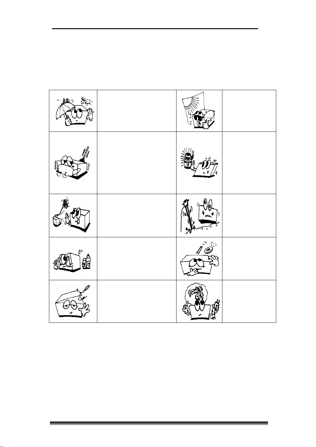
General Precaution on Environment
Do not keep or operate the equipment under the environment listed below.
Avoid placing in an area
exposed to moisture. Do not
touch the equipment with wet
hand.
Avoid placing in an area
where there is a high
variation of temperature.
Operating t emper ature
ranges fr om 10°C to 40°C.
Operating humidity ranges
from 30% to 85%.
Avoid exposure to
direct sunlight
Avoid in the vicinity
of Electric heater
Avoid placing in an area
where there is an
excessive humidity rise or
ventilation problem.
Avoid placing in an area
where chemicals are
stored or where there is in
danger of gas leakage.
Do not disjoint or
disassemble the equipment.
BISTOS Co., Ltd. does not
take responsibility of it.
Avoid placing in
an area where
there is an excessive
shock or vibration.
Avoid dust and
especially metal
material into the
equipment.
the equipment is
not fully installed.
Otherwise, the
equipment could
Page 9
BT-700 Operator Manual 9
P/N : 700-ENG-OPM-EUR-R02
Bistos Co.,Ltd.
2018,03
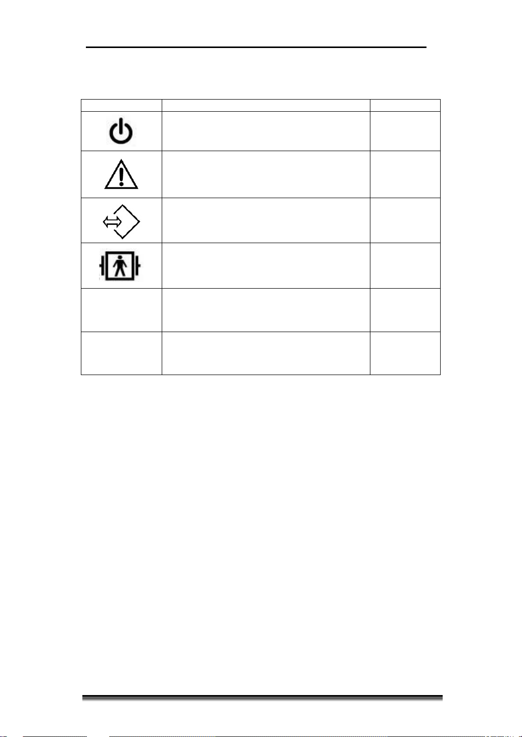
Symbol
Description
Requirements
This symbol identifies a safety note . Ensure you
using it. Control function is described in the
operator’s manual.
1.4 Definitions and Symbols
Power On/Off Button IEC TR 60878
understand the function of this control before
External Signal IN/OUT Port IEC TR 60878
Defibrillation-proof type BF applied part IEC60601-1
IPX7
IPX2
IPX7 W ater -proof (Temperature, type rectal) IEC60529
IPX2 Water-proof (SpO2 sensor ) IEC60529
IEC 60601-1
Page 10

BT-700 Operator Manual 10
P/N : 700-ENG-OPM-EUR-R02
Bistos Co.,Ltd.
2018,03
Section 2
Introduction
2.1 Brief Device & Intended purpose
The BT-700 is a Patient monitor. It measures the SpO2, pulse rate and temperature. It
provides continuous and noninvasive information on two important physiological
parameters: arterial blood oxygen saturation and pulse rate. This information is
obtained through measurement of light inten sity transmitted across the finger at two
distinct wavelengths, in the red and near-infrared regions of spectrum. This monitor
measures functional saturation – oxygenated hemoglobin expressed as a percentage of
the hemoglob in that can transport oxygen. It does not detect significant amounts of
dysfunctio na l he mo gl ob i n, such as carboxyhemoglobin or methemoglo b in. I n co ntr a st ,
hemoximete rs such as the IL482 repor t fractional saturation – oxygenated hemoglobin
expressed as a percentage of all measured hemoglobin, including measured
dysfunctional he moglobins. To compare functional sat uration measurement s to those
from an instrument that measures frac tional saturation, fractional measurements must
be converted as follows the temperature is measured in the patient’s rectal. The
resistance value of the temperature sensor is changed for the patient’s rectal
temperature. BT-700 measures it’s resistance, and calculates the temperature.
BT-700 has the Auto-calibration functions for each other patient. Internal calibration
function starts calibrating when the pa tient is monitored.
This device is for use onl y by trained medical perso nnel located in hospitals, clinics,
doctor’s offices.
Page 11

BT-700 Operator Manual 11
P/N : 700-ENG-OPM-EUR-R02
Bistos Co.,Ltd.
2018,03
WARNING:
WARNING:
WARNING:
2.2 Options and Accessories
Basic Accessories
The following are the basic specifications. To open the packaging to make sure that
the following accessories.
① BT-700 Body : 1 ea
② Re-usable SpO2 sensor probe : 1 ea
③ SpO2 Extension cable : 1 ea
④ Power adapter : 1 set
⑤ Power Cord : 1 ea
⑥ Operator manual : 1 ea
Option Accessories
The following is optional. I f you wish to purchase, please contact our office.
① Disposable SpO2 sensor probe
② Temperature sensor probe (Type : Rectal)
③ I-V holder
- BT-700 and The SpO2 sensor are certificated with international s tandards.
- The SpO2 sensor of BT-700 is type ne llcor SpO2 se nsor.
- The extension cable of BT-700 is available in the BT-700 only. If you use a
different cable, check the compatibility
- Power adaptor :
Only use the ‘Power Bridge Corporation – JMW110 9Vdc, 1.5A’
- The Temperature sensor of BT-700 is used only rectal type.
- The Temperature sensor of BT-700 is calibrated with YSI temperature
sensor.
Page 12

BT-700 Operator Manual 12
P/N : 700-ENG-OPM-EUR-R02
Bistos Co.,Ltd.
2018,03
Section 3
Installation
3.1 Descri pti on of the BT-700 Front Panel
Fig. 3.1 BT-700 Front Panel
① Power On/Off Button
② Power Indicating LED ( AC: Green / Battery:Orange)
③ TFT-Color LCD
④ Mode Change Button
⑤ Trend Save Button
⑥ Alarm On/Off Button
⑦ Bright Button
⑧ Control Knob, Enter then Menu and Control Beep V ol um e
⑨ Mode Change Status Led
⑩ Trend Save Status Button
⑪ Alarm On/Off Button
3.2 Descripti on of the Side Panel
① SpO2 Sensor Connector ① SpO2 Sensor Holder
② Temperature Sensor Connector
Fig. 3.2 Left Panel Fig. 3.3 Right Panel
Page 13

BT-700 Operator Manual 13
P/N : 700-ENG-OPM-EUR-R02
Bistos Co.,Ltd.
2018,03
3.3 Description of the Rear Panel
⑧
Fig. 3.4 Rear Panel
⑦
①
②
⑤
④ ⑥
③
① Grip
② Battery Cover
③ Power Adaptor Jack Connector
④ RS-232C Port Connector ( Only for Technical engineer)
⑤ USB Port Connector
( For Firm Ware Upgrade , Only for Technical engineer)
⑥ Dip Switch
⑦ Speaker
⑧ SpO2 Sensor Holder
3.4 Power On & Probe Connection
When the use r want to turn BT-700 on, power adaptor is connected with BT-700
below Figure 3.5 and power button is pressed for 2 seconds(refer to Fig. 3.1). Also
SpO2 Sensor probe is connected below Figure 3.5
Fig. 3.5 Power adaptor and Probe Connection
Page 14

BT-700 Operator Manual 14
P/N : 700-ENG-OPM-EUR-R02
Bistos Co.,Ltd.
2018,03
Target
Adult
ID
00000
Name
Empty
Data Interval
1 minute
Adult 100%,
Neonate 80%
Adult 85%,
Neonate 80%
Adult 170 bpm,
Neonate 190 bpm
Adult 40bpm,
Neonate 90 bpm
Alarm Period
30 s
Section 4
BT-700 Operation
4.1 Factory Setting
When BT-700 is turned on with pressing the knob button, enters in a factory mode.
In factory mode, configuration parameter is initialized. These parameters are
unaffected when the monito r is powered down. A complete list of these parameters is
shown below
Setting Parameter Factory Default
Monitoring Mode Graph mode
Alarms Volume 3
SpO2 Limits High
SpO2 Limits Low
PR Limits High
PR Limits Low
4.2 BT-700 Display Screen
Fig. 4.1 Main Monitoring Screen – Graph Mode
Page 15

BT-700 Operator Manual 15
P/N : 700-ENG-OPM-EUR-R02
Bistos Co.,Ltd.
2018,03
Fig. 4.2 Main Monitoring Screen – Numeric Mode
Fig. 4.3 Main Monitoring Screen – Spo2 Trend Mode
Fig. 4.4 Main Monitoring Screen – Pulse rate Trend Mode
Page 16

BT-700 Operator Manual 16
P/N : 700-ENG-OPM-EUR-R02
Bistos Co.,Ltd.
2018,03
℃).
Fig. 4.5 Main Monitoring Screen – Temperature Mode
When mode button [MODE] is pressed, select the “ ‘Graph Mode’ ‘Numeric
Mode’ ‘SpO2 Trend Mode’ ‘Pulse rate Trend Mod e’ ‘Temperature mode ’
“ item in sequence.
4.2.1 Parameter Frame
The Parameter frame shows the current Measuring parameter of patient. There
are SpO2 (%), Pulse rate ( BPM : beat per minute) and Temperature (
4.2.2 SpO2 Frame
The SpO2 Frame displays the percentage of hemoglobin binding sites in the
bloodstream occupied by oxygen.
4.2.3 Pulse Rate Frame
The Pulse Rate Frame displays beats per minute of th e Patient’s pulse rate.
4.2.4 Alarm Limits Frame
The Alarm Limits Frame displays the Alarm Limits set by operator.
4.2.5 Plethysmograph Frame
The Plethysmograph Frame displays a graphical representation of the blood
perfusion.
4.2.6 Temperature Frame
The Pulse Rate Frame displays the temperature of the Patient’s pulse rate.
4.2.7 SpO2 trend Frame and Pulse rate trend Frame
The SpO2 trend Frame and the Pulse rate trend Frame displays a graphical
representation of the SpO2 or the Pulse rate during 240 seconds .
Page 17

BT-700 Operator Manual 17
P/N : 700-ENG-OPM-EUR-R02
Bistos Co.,Ltd.
2018,03
Display mode Change
SpO2 Trend mode
Pulse rate trend mode Temperature mode]
CAUTION: Never use sharp or pointed objects to operate the front-panel
4.2.8 Alarm message & Time Frame
This frame shows the current time and date for the monitor or the Alarm
message in the ala rm status.(See chapter 6 about the Alarm message ).
The Time settings can be changed as needed.
4.2.9 Status Frame
This frame shows ba tte ry status, probe connecting status, and saving status.
symbol Name Description
Beep volume Icon Indicates the Beep volume . (Only HR beep)
Alarm Status Icon
Indicates the Alarm status (On/ P e riodic Off/
always o ff ).
Adult Icon Indicates that the measuring patient is Adult.
Neonate Icon Indicates that the measuring patient is Neonate.
Battery Status Icon
Indicates the battery charge status
4.3 BT-700 Controls and Indicators
There are seven buttons located on the front panel. The buttons are activated by
pushing with the finger until an audible click is heard.
switches.
The operation of the buttons is summarized below.
Symbol Description
Turn power on or off.
MODE
TREND
ALARM
BRIGHT
[ Graph Mode Numeric Mode
Save function is on or off.
Alarm On/ Alarm Suspend during setting time (off - 30s 60s - 90s : user selectable in alarm of menu) / Alarm Off.
Control the Fro nt LCD Brightness.
Page 18

BT-700 Operator Manual 18
P/N : 700-ENG-OPM-EUR-R02
Bistos Co.,Ltd.
2018,03
Level 1
Level 2
Level 3
Default setting
System Setup
Target
Adult
Language
English
Alarms
SpO2 High/Low
Adult
H : 95 L : 80
PR High/Low
Adult
H : 190 L : 90
Alarm Temporary
30 s – 60s – 90s –
(default 120s)
Alarms Volume
3 Clock
Time Set
Time Format
Date Set
20yy/mm/dd
Patient Data
ID 00000
Name
AAAAAAAAAA
Trend Data
Data Interval
1 Min
List Type
Chart
Data List
Delete All Data
No
CAUTION: Pre ssi n g the kno b when “Memory All Delete”, saved data is
4.4 BT-700 Control Knob
In each mode, the control knob decrease and increase the pulse beat audio
volume and push the knob, you can enter the menu.
In the other mode, the Control Knob is the method of adjusting parameters and
navigatin g t hrough the menu system. If the knob is rotated while in a menu, the
cursor moves throughout t he items within the menu. This p rocess is used to
select a menu item for modification. The knob is then pressed to select this item
for editing.
Once a menu item has been selected for editing, the knob is rotated to scan
through the available choices for this parameter. Pressing the knob stores the
new value temporarily.
deleted.
4.5 Menu Tree
The Menu Tree of BT-700 is such as table 4.4
limits (%)
limits (BPM)
Silence
H : 100 L : 85
Neonate
H : 170 L : 40
Neonate
120s off
Table. 4.4 Trend Mode display
Page 19

BT-700 Operator Manual 19
P/N : 700-ENG-OPM-EUR-R02
Bistos Co.,Ltd.
2018,03
4.6 Data Saving
BT-700 has a data saving function. It can save up t o 72 hours (data interval :
1minute ). Saving parameters are the SpO2, the Pulse rate and the Temperature.
4.6.1 How to save data
Press mode button [Trend] to start saving. When the function is stared, the save icon
] is activated and rotated.
[
Press mode button [Trend] again to stop saving.
4.6.2 Trend Data (Data list)
Control the knob to enter the saved data list of the Trend data. In data list, the saved
data is patient ID, Save start time and end time. Select ID by controlling Knob. Figure
4.x is displayed.
Fig. 4.4 Trend Mode display
Select the saved list by controlling the knob. Fig 4.5 is displayed.
Fig. 4.5 Saved Data Tracing Mode display
Page 20

BT-700 Operator Manual 20
P/N : 700-ENG-OPM-EUR-R02
Bistos Co.,Ltd.
2018,03
Section 5
Operation
5.1 Electromagnetic Interference
Certain strong electromagnetic fields can interfere with the SpO2 sensor and
cause a false SpO2, Pulse rate and temperature reading that does not originate
from the pat ient. This interfe rence is rare, and usually found in the vicinity of
large machinery. In order to avoid the possibility of these interfering signals
being misinte rpreted, the following proc edure should b e followed wheneve r the
monitor is to be used in a new location, or if it is known that electrical machinery
is being operated in the vicinity.
After connecting the SpO2 sensor, tur n o n t he mo nit or a nd o b ser ve the pulse rate
indications on the screen for 30 seconds. Intermittent display of random heart
rates is acceptable. However, if there is a constant display of a physiological
pulse rate la sting more than 5 seconds, this is an indication that there is a source
of electromagnetic interference in the vicinity. The following steps should be
taken to determine if it is possib le to use the monitor in this environment.
Move all line cords and line-p owered equipment at least 6 feet away from
the BT-700. Check for exte nsi on co rd s runnin g be hind or under the b ed and
equipment in adjacent rooms. If the artifact pulse rate indication ceases, the
monitor may be used normally.
Remove the li ne cord from the monitor’s power supply. If the artifact pulse
rate indication ceases, the monitor may be used normally.
If these measures do not result in cessation of the pulse rate artifact, the monitor
cannot be safely used in this environment.
5.2 Basic operation
The BT-700 uses pulse oximet r y to meas ur e fu nc tio na l o xyge n saturation in the blood.
Pulse oxime tr y wo rks by applying a se nso r to a pulsating arteriolar vascular bed, such
as a finger or toe. The sensor contains a dual light source and a photo detector. Bone,
tissue, pigmentation, and venous ve ssels normally absorb a c onstant amou nt of light
over time. The arteriolar bed normally pulsates and absorbs variable amounts of light
during the pulsations. The ratio of light absorbed is translated into a measurement of
functional o xygen saturatio n (SpO2). B ecause a measurement of SpO2 is dependent
upon light from the sensor, excessive ambient light can interfere with this
measurement. Speci fic information about ambient conditio ns, sensor application, and
patient conditions is contained throughout this manual. Pulse oximetry is based on
two principles: that oxyhe moglobin and deoxyhemoglobin differ in their absorption of
red and infra red light (spectrophotometry), and that the volume of arterial blood in
tissue (and hence, light absorption by that blood) changes during the pulse
(plethysmography). A pulse oximeter determines SpO2 by passing red and infrared
light into an arteriolar bed and measuring changes in light absorption during the
pulsatile cycle. Red and infrared low-voltage light-emitting diodes (LED) in the
oximetry sensor serve as light sources; a photo diode serves as the photo detector.
Page 21

BT-700 Operator Manual 21
P/N : 700-ENG-OPM-EUR-R02
Bistos Co.,Ltd.
2018,03
Because oxyhemoglobin and deoxyhemoglobin differ in light absorption, the amount
of red and infrared light absorbed by blood is related to hemoglobin oxygen saturation.
To identify the oxygen saturatio n of ar te r ia l hemoglobin, the monitor uses the
pulsatile nature of arterial flow. Data update period of SpO2 and Pulse rate is 1second.
Step 1: Preparing the Monitor
Turn the mo ni tor on and veri fy that the nor mal monitoring screen appear s on the
display. Remove the monitor from service if an error occurs.
Check whether the monitor is powered from the internal battery or AC power. If
operating on the internal battery, check the power status frame on the display to
determine whether the battery has sufficient charge to complete the monitoring
session. Use the AC power if the battery is too low.
Step 2: Check the sensors ( the SpO2 sen sor and the temperature sensor)
Check the SpO2 sensor or the Temperature sensor to verify proper attachment
to the monitor. Check the emitter (red light) and the photo detector are properly
aligned. If measure the SpO2 and the Pulse rate, attach the spo2 sensor to the
patient’s finger. If measure the temperature, insert the temperature sensor ( only
rectal type) in the patient’s rectal.
Step 3: Acquiring t he SpO2, the Pulse rate and the temperature.
5.3 Detail Procedure
① Explain procedure to the patient.
② Attach the SpO2 sensor and/or the temperature sensor. Attach the SpO2
sensor to the patient’s index finger and insert the temperature sens or (type
rectal) into the patient’s rectal.
③ Turn the monitor power on. The po wer switch is located on the front panel.
Page 22

BT-700 Operator Manual 22
P/N : 700-ENG-OPM-EUR-R02
Bistos Co.,Ltd.
2018,03
Priority
Description
High Priority
Audible and visual alarms for detached the spo2 sensor at
Medium
Audible and visual alarms for exceeding the SpO2 Limits
detached sensor to the BT-700. Sound is “ bee bee bee”
Low Priority
Audible and visual alarms for low battery.
Sound is “bee - bee”
Priority
Visual messages
Description
High Priority
detached the spo2 sensor at the
patient’s finger.
Sensor error
Faulty SpO2 sensor is connected
Medium
exceeding the SpO2 Limits
exceeding the Pulse rate Limits
detached sensor to the B T-700.
Low Priority
low battery.
Silence Period
Description
OFF
Always mute
30 second
Silence for 30 seconds
60 second
Silence for 60 seconds
90 second
Silence for 90 seconds
120 second
Silence for 120 seconds
Section 6
Alarms and messages
In this Section, contains descriptions for Alarms and message of BT-700 unit.
6.1 Alarms priority
the patient’s finger. Sound is “ bee bee bee - bee bee”
Priority
Priority
and the Pulse rate. Audible and visual alarms for the
6.2 Alarms silence period
Alarms can be silenced for preset period called alarm silence duration. To view
the current setting, press [ALARM] button until 30sec, 60 sec, 120sec, or off is
displayed. To adjust the setting, enter “ MENU SYSTEM SETUP
ALARM “ using control knob, and select the desired period. If the [ALARM]
button is pressed during the alarm silence duration, the alarm silence duration is
ended and the audible alarms are re-enabled.
6.3 Alarms Volume Control
Alarm volume can be controlled in menu.
“ MENU SYSTEM SETUP ALARM VOLUME“
Page 23

BT-700 Operator Manual 23
P/N : 700-ENG-OPM-EUR-R02
Bistos Co.,Ltd.
2018,03
WARNING: Unplug the monitor from the AC power source and detach all
CAUTION: Take extra care when cleaning the display surfaces, which are
CAUTION: Do not autocla ve. Do not gas sterilize.
CAUTION: Do not immerse in liquid. When using solutions, use sterile
Section 7
Cleaning and Disinfection
This chapter contains instructions for the care and cleaning of the BT-700 unit
and its accessories.
The BT-700 requires proper care and preventive maintenance. This ensures
consistent operation and maintains the high level of performance necessary in
monitoring procedures.
7.1 Monitor
Keep the external surface clean and free of dust, dirt, and residual liquids.
Clean with a damp cloth using mild soap and water or hospital approved
nonabrasive disinfectants.
accessories before cleaning. Do not immerse the unit in water or allow liquids
to enter the case.
sensitive to rough handling. Rub the lens t hat covers them with a soft, dry
cloth.
7.2 Sensors
Cleaning and Disinfecting the SpO2 sensor and the temperature
sensor.
To avoid damage to the sensors, clean and disinfect only according to the
following instructions.
1. Wipe the device with a sterile wipe soaked in enzymatic detergent safe for
use with metal instruments. Wipe the exterior of the device three times.
Prepare the detergent according to the manufacturer’s sensor
recommendations.
2. Scrub sensors with enzymatic detergent using so ft b r istle d brush for five (5)
minutes. DO NOT IMMERSE SENSORS.
wipes to avoid pouring fluids directly on t he transducer.
Page 24

BT-700 Operator Manual 24
P/N : 700-ENG-OPM-EUR-R02
Bistos Co.,Ltd.
2018,03
WARNING: Before use, carefully read the sensor directions for use,
including all warnings, cautions, and instructions.
WARNING: Do not use a damaged sensor or pulse oximetry cable. Do not
use a sensor with exposure optical components.
WARNING: Use only one pulse oximetry cable to increase the length of the
WARNING: Pul s e oximetry rea dings and pulse signal can be affected by
patient conditions.
WARNING: Tissue damage can be caused by incorrect application or duration
directions for use.
WARNING: Do not immerse or wet the sensor.
3. Wipe sensors three (3) times with sterile water to remove soap residue.
4. Wipe the sensors wit h a sterile wipe soaked in Cidex™. Wipe all exterio r
surfaces of the transducer three (3) times.
5. Wipe the sensors three (3) times with sterile water to remove Cidex residue.
6. Dry the device thoroughly with a sterile soft towel or gauze surgical sponge.
7. Wrap the dry device in a fresh sterile so ft towel or transparent sterile wrap
for storage until next use.
sensor. Use of more than one pulse oximetry cable may have an adverse effect
on performance. Do not attach any cable that is intended for computer use to
the sensor port.
certain ambient environmental c onditions, sensor application errors, and certain
of use of the SpO2 sensor. Inspect the sensor site as directed in the sensor
Page 25

BT-700 Operator Manual 25
P/N : 700-ENG-OPM-EUR-R02
Bistos Co.,Ltd.
2018,03
Section 8
Troubleshooting and
Maintenance
8.1 Sensors
To test an Sensors:
1. Properly connect the Sensors to the right of the monitor.
2. Turn on the monitor.
3. Adjust the speaker volume to an audible level.
4. The Pulse Search indicator is lit for more than 10 seconds while
the sensor is connected to the patie nt.
5. The Pulse Search indicator lights after successful measurements
have been made.
8.2 Battery Disposal and Handling
Be cautious when disposing of internal Ni-MH battery.
Adhere to all applicable laws r e gar ding recycling. Avoid storing battery
above 60°C (140°F). If clothing or skin comes in contact with material from
inside the battery, immediately wash with plenty of clean water.
When you replace internal Ni-MH, contact to our technical support office.
8.3 Maintenance
BT-700 requires periodic calibration or adjustment. The recommended
interval for performing hipot and leakage testing is once per year.
If you need a Calibration or a adjustment, contact to our technical support
office.
8.4 Troubleshooting
(1) I f not Power on, change the power adaptor. And try again turn on the
power button.
(2) If not displayed SpO2 signal, change the SpO2 Probe.
(3) If not displayed Temperature value, change the temperature sensor.
Page 26

BT-700 Operator Manual 26
P/N : 700-ENG-OPM-EUR-R02
Bistos Co.,Ltd.
2018,03
Internal
6 V(1.2 V * 5ea),Ni-MH, rechargeable
External
AC/DC Adaptor
Output : DC 9 V, 1.5 A
Power
SpO2 sensor
Wavelength : RED 660 nm,
IRED 940nm
Operating Temperature
10°C to 40°C (50°F to 104°F)
Transfer & Storage
Temperature
Relative Humidity
20% to 90% non-condensing
Altitude:
0 -3048m (0 -10,000 ft)
Section 9
Specifications
BT-700 Monitor Specifications:
Physical Characteristic s
Main body : 90 mm(H) x 250 mm(L) x 118 mm(D)
Probe : 29.7mm(Ø) x 126.8mm(H)
Weight - approx. 1.5 kg
Safety
Complies with EN60601-1, EN60601-1-2, EN60601-2-37, ISO9919
Class II Equipment, Internally Powered Eq uipment
Continuous Operation
Defibrillation-proof type BF applied part
Probe Water-proof Level : SpO2 sensor IPX2 , Rectal type temperature sensor IPX7
EMC Class : Group I, Class B
Power
Consumption
Environmental
4 hours Fast C har ge
Continuously 6 hours
Input : AC100~240 V[50/60 Hz]
80VA, maximum
–20°C to 60°C (–4°F to 140°F )
Page 27

BT-700 Operator Manual 27
P/N : 700-ENG-OPM-EUR-R02
Bistos Co.,Ltd.
2018,03
Patient
Adult , Neonate, Pediatric
SpO2 and Pulse rate Measurement Range
SpO2 range
1% ~ 100%
Pulse Rate range
30 BPM ~ 250 BPM
Perfusion Ra nge
0.3% ~ 20%
SpO2 and Pulse rate Accuracy and Motio n Tolerance
SpO2
Without motion – Adult
±2 digits of range
Without motion – Neonate
±3 digits of range
With motion – Adult and Neonate
±3 digits of range
Pulse Rate
Without motion – Adult
±2 digits of range
Without motion – Neonate
±3 digits of range
With motion – Adult and Neonate
±3 digits of range
Temperature Range and Accuracy
Range and accuracy
20 °C ~ 45 °C ± 0.5 °C
SpO2 and Pulse rate Monitoring
Page 28

BT-700 Operator Manual 28
P/N : 700-ENG-OPM-EUR-R02
Bistos Co.,Ltd.
2018,03
Product Name
Patient monitor
Model Name
BT-700
Approval No.
Approval Date
Serial No.
Warranty Period
2 Years (Probe excluded)
Date of Purchase
Hospital:
Telephone:
Product Guarantee
Customer
Sales Agency
Address:
Name:
Manufacture BISTOS Co., Ltd.
※ Thank you for purchasing BT-700.
※ This product is manufactured and passed through strict
quality control and inspection.
※ Compensation standard concerning repair, replacement,
refund of the product complies with “Consumer’s protection
law” noticed by Economic Planning Dept.
Page 29

BT-700 Operator Manual 29
P/N : 700-ENG-OPM-EUR-R02
Bistos Co.,Ltd.
2018,03
Service Telephone and Fax. Numbers
Telephone: +82 31 750 0340
Fax: +82 31 750 0344
BISTOS Co., Ltd
www.bistos.co.kr
bistos@bistos.co.kr
Model Name: BT-700
7th FL., A Bldg., Woolim Lions Valley 5-cha, 302,
Galmachi-ro, Jungwon-gu, Seongnam-si, Gyeonggi-do, Korea
Obelis s.a
Bd. Général Wahis 53
1030 Brussels, BELGIUM
Telephone: + (32) 2. 732.59.54
Fax.: + (32) 2.732.60.03
 Loading...