

Page 1
BT-550
Operation Manual
Keep this manual for future reference
P/N : 550-ENG-OPM-EUR-R01
Page 2

BT-550 Operation manual
1
P/N : 550-ENG-OPM-EUR-R01
Bistos Co., Ltd.
2018.03
Information and descriptions contained in this manual are the property of Bistos Co., Ltd. and may not
be copied, reproduced, disseminated, or distributed without express written permission from Bistos
Co., Ltd.
Information furnished by Bistos Co., Ltd is believed to be accurate and reliable. However, no
responsibility is assumed by Bistos for its use, or any infringements of patents or other rights of third
parties that may result from its use. No license is granted by implication or otherwise under any patent
or patent rights of Bistos Co., Ltd.
The information contained herein is subjects to change without notice.
Prepared by:
Bistos Co., Ltd.
th
7
FL., A Bldg., Woolim Lions Valley 5-cha, 302,
Galmachi-ro, Jungwon-gu, Seongnam-si,
Gyeonggi-do, Korea
Telephone: +82 31 750 0340
Fax: +82 31 750 0344
Revision R01
Mar,2018
Printed in Korea
Copyright © Bistos Corporation 2018. All rights reserved.
Proprietary Material
Page 3

BT-550 Operation manual
2
P/N : 550-ENG-OPM-EUR-R01
Bistos Co., Ltd.
2018.03
Contents
0. Safety information ······················································································ 4
0.1 General precautions, warnings and cautions ···························································· 6
0.2 Shock hazards ············································································································· 9
0.3 General precautions on environment ······································································· 10
1. System basics ······························································································ 11
1.1 Indication for use ········································································································ 11
1.2 Operating principle ····································································································· 11
1.3 System configurations ································································································ 12
1.4 Product outlook ·········································································································· 14
1.5 Description of system components ············································································ 15
1.6 Understanding the display ························································································· 20
1.7 Buttons ······················································································································· 21
1.8 Alarm and warning indication ····················································································· 23
1.9 Essential performance ································································································ 25
2. Operation of BT-550····················································································· 26
2.1 Precautions ················································································································· 26
2.2 Assembling BT-550 ····································································································· 27
2.2.1 Repositioning the column ·················································································· 27
2.2.2 Installing the IV pole to column (option) ··························································· 30
2.2.3 Installing the plate for auxiliary equipment to column (option) ························ 31
2.3 Separating barriers ····································································································· 32
2.4 Tilting bed ··················································································································· 33
2.5 Skin temperature sensor ···························································································· 34
2.6 Prepare to use ············································································································· 35
2.7 Operation ···················································································································· 36
2.8 SpO2 Monitor(option) ······························································································· 39
3. Placing infant and moving BT-550 ································································ 46
3.1 Placing infant ·············································································································· 46
3.2 Move the BT-550 ········································································································ 46
3.2.1 Precautions ········································································································ 46
3.2.2 Stand caster lock ································································································· 47
4. Maintenance and cleaning ·········································································· 48
4.1 Service policy ·············································································································· 48
4.2 Maintenance ·············································································································· 48
4.3 Cleaning ······················································································································· 48
5. Trouble shooting ·························································································· 50
5.1 General ······················································································································· 50
5.2 Understanding alarms ······························································································· 50
Page 4

BT-550 Operation manual
3
P/N : 550-ENG-OPM-EUR-R01
Bistos Co., Ltd.
2018.03
6. Manufacturer’s declaration on EMC ·································································· 51
6.1 Electromagnetic emissions ····························································································· 51
6.2 Recommended separation distances between portable and mobile RF communications
equipment and the BT-550 ···························································································· 52
6.3 Electromagnetic immunity ······························································································ 53
7. Technical specifications ···················································································· 55
Product Warranty ·································································································· 57
Figure 1-1: Front View ··············································································································· 14
Figure 1-2: Side view ················································································································· 14
Figure 1-3: System components ································································································ 15
Figure 1-4: Head ························································································································ 16
Figure 1-5: Column ···················································································································· 17
Figure 1-6: Bassinet ··················································································································· 18
Figure 1-7: Stand part ················································································································ 19
Figure 1-8: Display when SpO
Figure 1-9: Display when SpO
Figure 1-10: Buttons ·················································································································· 21
Figure 1-11: POWER Fail ············································································································· 23
Figure 1-12: Sensor Disable ········································································································ 23
Figure 1-13: S1 Tem p Erro r ········································································································· 23
Figure 1-14: S2 Tem p Error ········································································································ 23
Figure 1-15: Baby Check ············································································································· 23
Figure 1-16: Head Rotation ········································································································ 23
Figure 1-17: Masimo Check Alarm ····························································································· 24
Figure 1-18: Masimo Alarm Message ························································································· 24
Figure 2-1: Repositioning the column (1) ·················································································· 27
Figure 2-2: Repositioning the column (2) ·················································································· 28
Figure 2-3: Repositioning the column (3) ·················································································· 29
Figure 2-4: Installing IV pole ······································································································ 30
Figure 2-5: Installing plate for auxiliary equipment ··································································· 31
Figure 2-6: Separating barriers ·································································································· 32
Figure 2-7: Tilting handles ·········································································································· 33
Figure 2-8: Skin temperature sensor ·························································································· 34
Figure 2-9: Power cord ··············································································································· 35
Figure 2-10: Product logo and initial screen··············································································· 35
Figure 2-11: Caster locks ············································································································ 47
option not installed ·································································· 20
2
option installed ········································································· 20
2
Page 5
BT-550 Operation manual
4
P/N : 550-ENG-OPM-EUR-R01
Bistos Co., Ltd.
2018.03
WARNING
CAUTION
Used to identify safety information.
During the operation, do not disconnect any cable.
his symbol indicates the authorized representative in the European
0 Safety information
Before using BT-550 Infant warmer, read this entire manual and be fully understood the following
safety information to prevent injury of patient and user.
Symbols Used
The following symbols identify all instructions that are important to safety. Failure to follow these
instructions can lead to injury or damage to the infant warmer. When used in conjunction with the
following words, the symbols indicate:
Can lead to serious injury or death.
Can lead to minor injury
The following symbols are placed on product, label, packaging and this manual in order to stand for
the information about:
Be well-known this information thoroughly before using BT-550.
Indicate the warning for hot surface.
IPX0 IPX0 Non-protected against ingress of water with harmful effects.
IPX1
IPX2
IPX6
IPX1 Protected against the vertically dripping water
(Skin temperature sensor_2EA)
IPX2 Protected against the dripping water
(SpO2 sensor)
IPX6 Protected against the powerful jetting
(Foot switch_2EA)
Refer to operation manual. Read manual before placing the device.
Indicates the weight limit
This symbol indicates the manufacturer.
This symbol indicates the serial number of the device.
T
Community of manufacturer.
This symbol indicates a type BF applied part.
This symbol indicates to keep the device dry.
This symbol indicates the device is fragile.
Page 6
BT-550 Operation manual
5
P/N : 550-ENG-OPM-EUR-R01
Bistos Co., Ltd.
2018.03
This symbol indicates the temperature limitation for operation, transport
This symbol indicates the humidity limitation for operation, transport and
This symbol indicates the compliance with the essential requirements and
This symbol indicates to not dispose the device together with
In order to comply with EU Directive 2002/96/EC on Waste Electrical and
Electronic Equipment (WEEE): This product may contain material which
DO NOT
be RECYCLED in accordance with local regulations, contact your local
and storage.
storage.
This symbol indicates the packing material is recyclable.
provisions of the Medical Device Directive 93/42/EEC as amended by
2007/47/EEC.
unsorted municipal waste(for EU only). The solid bar symbol indicates
that mains adapter is put on the market after 13 August 2005.
DISPOSAL
could be hazardous to human health and the environment.
DISPOSE of this product as unsorted municipal waste. This product needs to
authorities for more information. This product may be returnable to your
distributor for recycling - contact the distributor for details.
Page 7

BT-550 Operation manual
6
P/N : 550-ENG-OPM-EUR-R01
Bistos Co., Ltd.
2018.03
Thoroughly read and understand the manual prior to use of the BT-550. Failure
s directed by an appropriately
se of accessories other than those listed and approved for use with this
rtified accessories with the appropriate International
Medical electrical equipment needs special precautions regarding EMC and
The equipment shall not be used adjacent to other devices unless verification of
0.1 General precautions, warnings and cautions
• Examine the warmer and any accessories periodically to ensure that the cables, line cords and
instruments do not have visible evidence of damage that may affect patient safety or
performance. The recommended inspection interval is once per week or less. Do not use the
warmer if there is any visible sign of damage.
• Only the AC line cord supplied with the BT-550 is approved for use with the Unit.
• Do not attempt to service the BT-550 infant warmer. Only qualified service personnel by
Bistos Co. Ltd., should attempt any needed internal servicing.
• The BT-550 is not specified or intended for operation during the use of defibrillators or during
defibrillator discharge.
• The BT-550 is not specified or intended for operation in the presence of electrosurgical
equipment.
• The BT-550 is not specified or intended for operation in conjunction with any other type of
equipment except the specific devices that have been identified for use in this Operator’s
Manual.
• Perform periodic safety testing to insure proper patient safety. This should include leakage
current measurement and insulation testing. The recommended testing interval is once per
year.
• Do not operate the BT-550 infant warmer if it fails to pass the power on self-test procedure.
WARNING
to do so could result in personal injury or equipment damage.
Infant warmer misuse may result in harm to an infant. Only properly trained
personnel should use the infant warmer a
qualified attending physician aware of currently known risks and benefits.
U
product may result in increased emissions or decreased immunity.
Use only ce
Electrotechnical Commission (IEC) 60601 harmonized national standard.
needs to be installed and put into service according to the EMC information
provided in this manual. In addition, portable and mobile RF communications
equipment can affect medical electrical equipment.
Page 8

BT-550 Operation manual
7
P/N : 550-ENG-OPM-EUR-R01
Bistos Co., Ltd.
2018.03
normal operation in the configuration in which it is to be used can be achieved.
could result in personal injury or
or use it
must be in direct contact with the skin to provide
Do not use in the presence of flammable anesthetics. Personal injury or
and burn with great intensity in air enriched with oxygen. Personal injury or
To avoid overheating the infant due to direct radiation, do not position the
monitor shelf, always place the monitor in the center of the shelf, ensure that
For proper operation of the infant warmer, use only skin temperature sensor
from Bistos Co. Ltd. Using other sensor
equipment damage.
Never place the skin temperature sensor under the infant’s body
rectally. Personal injury could occur.
The skin temperature sensor
accurate measurement of the infant’s skin temperature. Failure to maintain
direct skin contact can result in overheating. Routinely check the infant’s
condition for correct sensor attachment, and feel the infant’s skin for signs of
overheating.
equipment damage could occur.
Keep matches, and all other sources of ignition, out of the room in which the
infant warmer is located. Textiles, oils, and other combustibles are easily ignited
equipment damage could occur.
Small quantities of flammable agents, such as ethyl and alcohol, left on the
infant warmer may cause a fire in connection with oxygen. Personal injury or
equipment damage could occur.
A fire and explosion hazard exists when performing cleaning or maintenance
procedures in an oxygen-enriched environment.
infant warmer in direct sunlight or under other sources of radiant heat.
To prevent accidental disconnection when adjust the height, ensure that all
patient leads, infusion lines, and ventilator tubing have sufficient excess length.
For infant’s safety, do not leave the infant unattended. Personal injury could
occur.
Never place objects taller than the top of the wheel casters beneath the infant
warmer stand. Personal injury of equipment damage could occur.
For optimum stability, always lock all stand wheels. Do not leave the device
unattended when parking on an incline. Failure to do so could result in personal
injury or equipment damage.
Prior to placing the infant in the infant warmer, pre-warm the BT-550 to the
temperature prescribed by the attending physician, or according to nursing
protocol.
Only one monitor shelf should be used per infant warmer. When using the
Page 9

BT-550 Operation manual
8
P/N : 550-ENG-OPM-EUR-R01
Bistos Co., Ltd.
2018.03
the monitor fits within the border of the shelf, and avoid stacking monitors on
manual and found to comply with all relevant safety and performance
person or organization who makes an unauthorized modification, or
550 yourself to avoid damage to the
equipment and unexpected electrical shock. Only qualified Bistos service
heck the rating of power source compatible with the input voltage rating of
materials such as watch and ring and touch only the
the shelf. Personal injury or equipment damage could occur.
Attach the infant warmer to the stand using the bolts provided. Failure to do so
could result in the infant warmer separating from the stand if sufficiently tilted.
Personal injury or equipment damage could occur.
This product has been validated with the accessories and options listed in this
requirements applicable to the device. It is therefore the responsibility of that
incorporates an unapproved attachment to the device.
An operator may only perform maintenance procedures specifically described
in this manual.
Do not remove the covers of a BT-
engineer must repair or replace components.
C
BT-550.
The UART port is for debugging purposes only. It does not allow connections
with other devices.
Take off the metallic
insulated plastic part of BT-550
Page 10

BT-550 Operation manual
9
P/N : 550-ENG-OPM-EUR-R01
Bistos Co., Ltd.
2018.03
Unplug the unit from its power source prior to cleaning or maintenance to prevent
ome chemical cleaning agents may be conductive and leave a residue that may
o not allow cleaning agents to
To ensure grounding reliability, plug the AC power cord only into a properly
Do not expose the unit to excessive moisture that would allow for liquid pooling.
The total power of all equipment connected to the convenience outlet strip on the
the electrical requirements shown on the rear of the stand.
uilding power source is compatible with the electrical
0.2 Shock hazards
WARNING
personal injury or equipment damage.
S
permit a build-up of conductive dust or dirt. D
contact electrical components and do not spray cleaning solutions onto any of
these surfaces. Personal injury or equipment damage could occur.
grounded 3-wire hospital-grade or hospital-use outlet. Do not use extension cords.
If any doubt exists as to the grounding connection, do not operate the equipment.
Personal injury or equipment damage could occur.
Personal injury or equipment damage could occur.
Do not touch the patient and signal input/output parts simultaneously
Due to the risk of electrical shock hazard, only qualified personnel with appropriate
service documentation should service the unit.
stand must be within
Otherwise, personal injury or equipment damage could occur.
Make sure the b
specifications shown on the column of the stand and on the infant warmer. Failure
to do so could result in personal injury or equipment damage.
To prevent equipment damage or accidental power disconnections, do not plug a
BT-550 power cord directly to an AC wall socket when the BT-550 is mounted on a
pedestal /stand. Always provide power to the BT-550 by using the power cord
coming directly from the pedestal /stand.
Page 11
BT-550 Operation manual
10
P/N : 550-ENG-OPM-EUR-R01
Bistos Co., Ltd.
2018.03
Avoid placing in an area
Power off when the
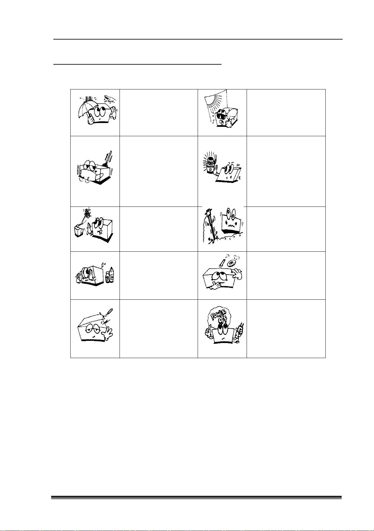
0.3 General precautions on environment
Do not keep or operate the equipment under the environment listed below.
Avoid placing in an area
exposed to moisture. Do
not touch the equipment
with wet hand.
where high variation of
temperature exists.
Operating temperature
ranges from 18
Operating humidity
ranges from 0 % ~ 95 %.
℃ ~ 30℃.
Avoid exposure to direct
sunlight
Avoid in the vicinity of
electric heater.
Avoid placing in an area
where there is an
excessive humidity rise
or ventilation problem.
Avoid placing in an area
where chemicals are
stored or where there is
in danger of gas leakage.
Do not disjoint or
disassemble the device.
Bistos Co., Ltd. does not
have liability of it.
Avoid placing in an area
where there is an
excessive shock or
vibration.
Avoid dust and especially
metal material enter into
the equipment
equipment is not fully
ready to operate.
Otherwise, the
equipment could be
damaged.
Page 12

BT-550 Operation manual
11
P/N : 550-ENG-OPM-EUR-R01
Bistos Co., Ltd.
2018.03
1 System basics
1.1 Intended use
The BT-550 Infant Warmer is intended to emit controlled, evenly distributed overhead heat to the body
of premature infant and other newborns that cannot effectively regulate their body temperature. This
device can be used before any treatment or operation of an infant. The device has two operating
functions; the baby mode and the manual mode. In the baby mode, the temperature is controlled by
the infant’s skin temperature. The infant’s skin temperature is compared to the temperature setting. If
the measured skin temperature is lower than a temperature setting value, the warmer operates to
increase the skin temperature of an infant. In the manual mode, the warmer operates for a predefined
time.
The device has the option for weighing scale and SpO2 measuring functions. Weight and SpO2 of infant
can be measured using the options. In the SpO2 measurement, the sensor is place at the end of a
finger. By measuring the intensity of reflected light, depending on the concentration of dissolved
oxygen in the blood determines the oxygen concentration.
1) Intended patient population
- Newborns, Premature infant, Low birth weight infant
- Age up to 3 months
- Weight up to 10 Kg
2) Intended user profile
- Nursing staff or physicians who is qualified personnel
- Basic experiences or knowledge on medical field, especially on obstetrics
- Trained or requested to read IFU before use
3) Environment of use
- Hospital (birthing center, delivery rooms), Neonatal intensive care unit (NICU)
- Requirements: Stable power source
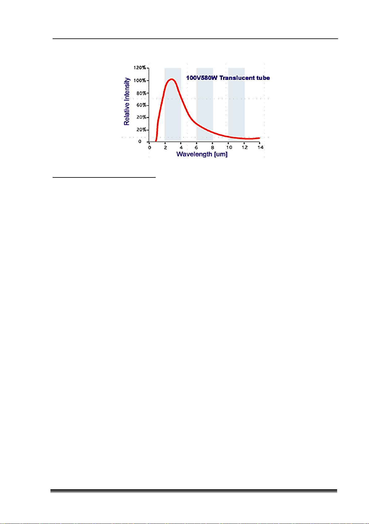
1.2 Operating principle
The BT-550 infant warmer is electrically powered device with a radiant heating source intended to
maintain the thermal balance of an infant by direct radiation of energy in the infrared region of the
electromagnetic spectrum. The maximum irradiance level at any point on the mattress is 100% heater
output, 28 ㎽/㎠±20% in the total infrared spectrum.
The following graph shows the emissivity data of infrared radiation used for the BT-550 Infant Warmer.
It has the specific frequency band of 2 ~ 11㎛.
Page 13
BT-550 Operation manual
12
P/N : 550-ENG-OPM-EUR-R01
Bistos Co., Ltd.
2018.03
1.3 System configurations
Basic configuration of BT-550
• Main body with fixed height stand
• Mattress & Power cable
• 2 skin temperature sensor
Options of BT-550
• Motor-driven height adjustable stand (Lift stand)
• Intravenous(IV) pole
• IV Plate for auxiliary equipment
• Basket(Drawer)
• Basket partition
• Weighing scale
• Bed tilting mechanism
• SpO
2
• Extension for SpO2 sensor
Page 14
BT-550 Operation manual
13
P/N : 550-ENG-OPM-EUR-R01
Bistos Co., Ltd.
2018.03
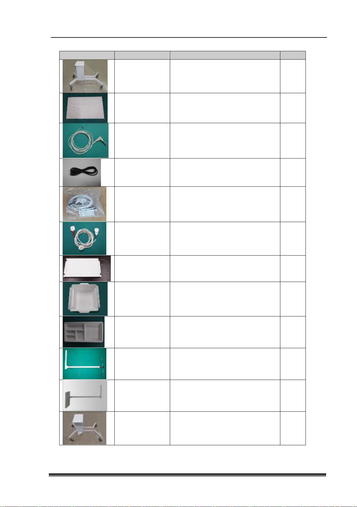
Picture
Name
Description
Qty
Masimo
(Optional)
Fixed Stand
(Standard)
Mattress
(Standard)
Skin temperature
sensor (Standard)
AC power code
(Standard)
Masimo SpO2
sensor probe
(Optional)
Extension for
SpO2 sensor
Movable warmer cradle with wheels 1ea
Accommodate infant stably with
bouncy mattress
1ea
Measures infant’s skin temperature 2ea
AC Power cord(AC Power cord for
operating the equipment)
1ea
Measures infant’s SpO2 1ea
Extend sensor cable 1ea
Weighting Scale
(Optional)
Basket (Optional)
Basket Partition
(Optional)
IV-pole
(Optional)
IV plate
(Optional)
Lift Stand
(Optional)
Measures Infant’s weight 1ea
Store medical equipment and items
which infant needs
1ea
Partition of Basket 1ea
IV hanger 1ea
Plate to place items which infant
needs
Movable warmer cradle with wheels
(VHA- Variable Height Adjustable)
1ea
1ea
Page 15
BT-550 Operation manual
14
P/N : 550-ENG-OPM-EUR-R01
Bistos Co., Ltd.
2018.03
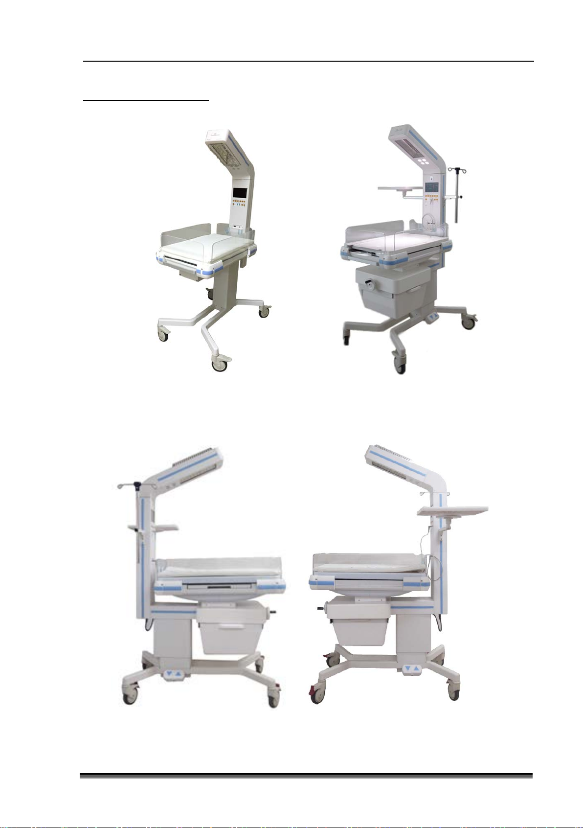
1.4 Product outlook
Basic configuration Configuration with full Options
Figure1-1: Front view
Figure1-2 : Side view
Page 16
BT-550 Operation manual
15
P/N : 550-ENG-OPM-EUR-R01
Bistos Co., Ltd.
2018.03
Equipped with infrared radiating light source and can be rotated
Supporting head part and equipped with electronic circuits to
he electronic circuits are composed with
side of column when the option has been selected.
Equipped with mattress and protective barriers to prevent the
easy access to infant patient.
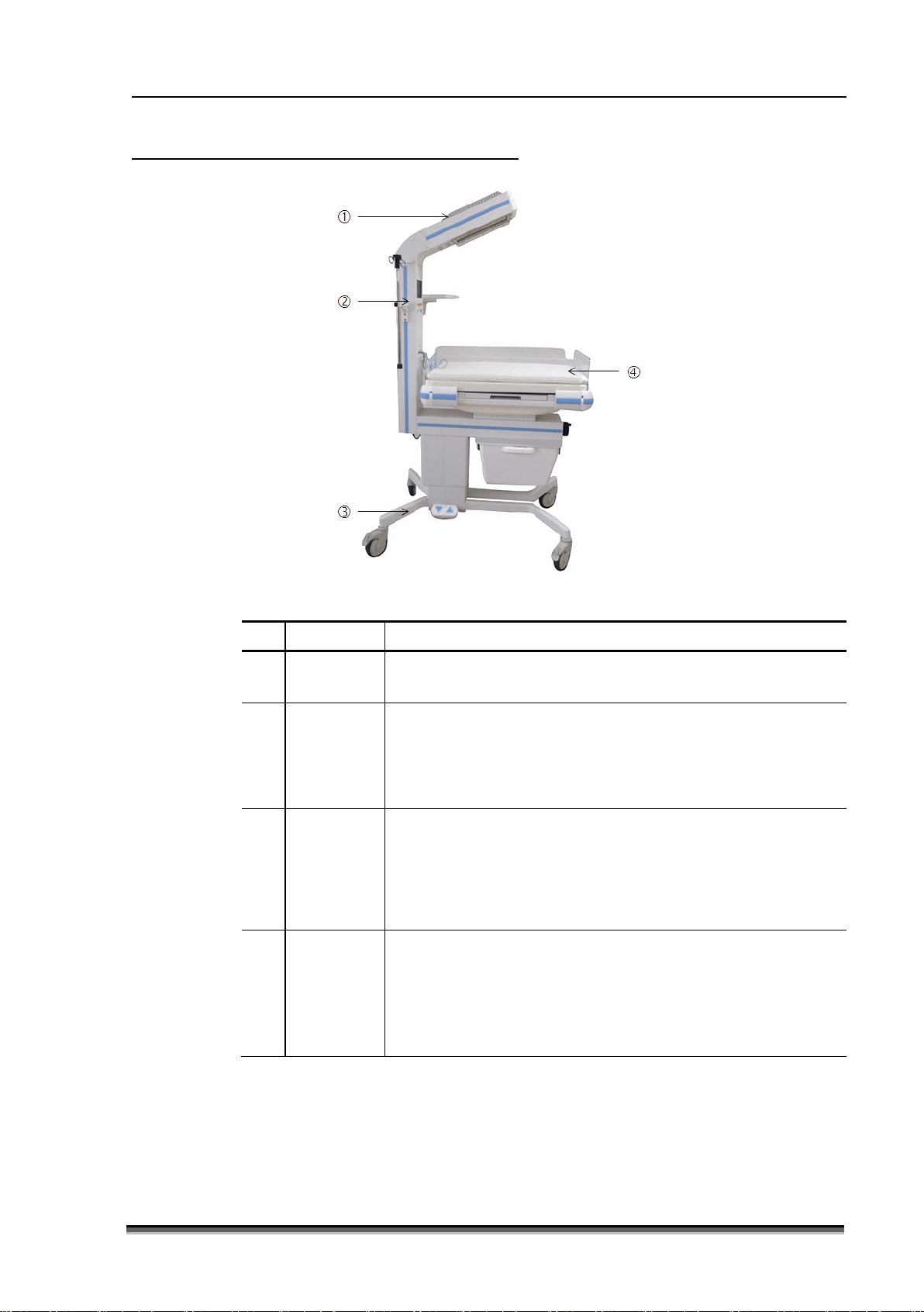
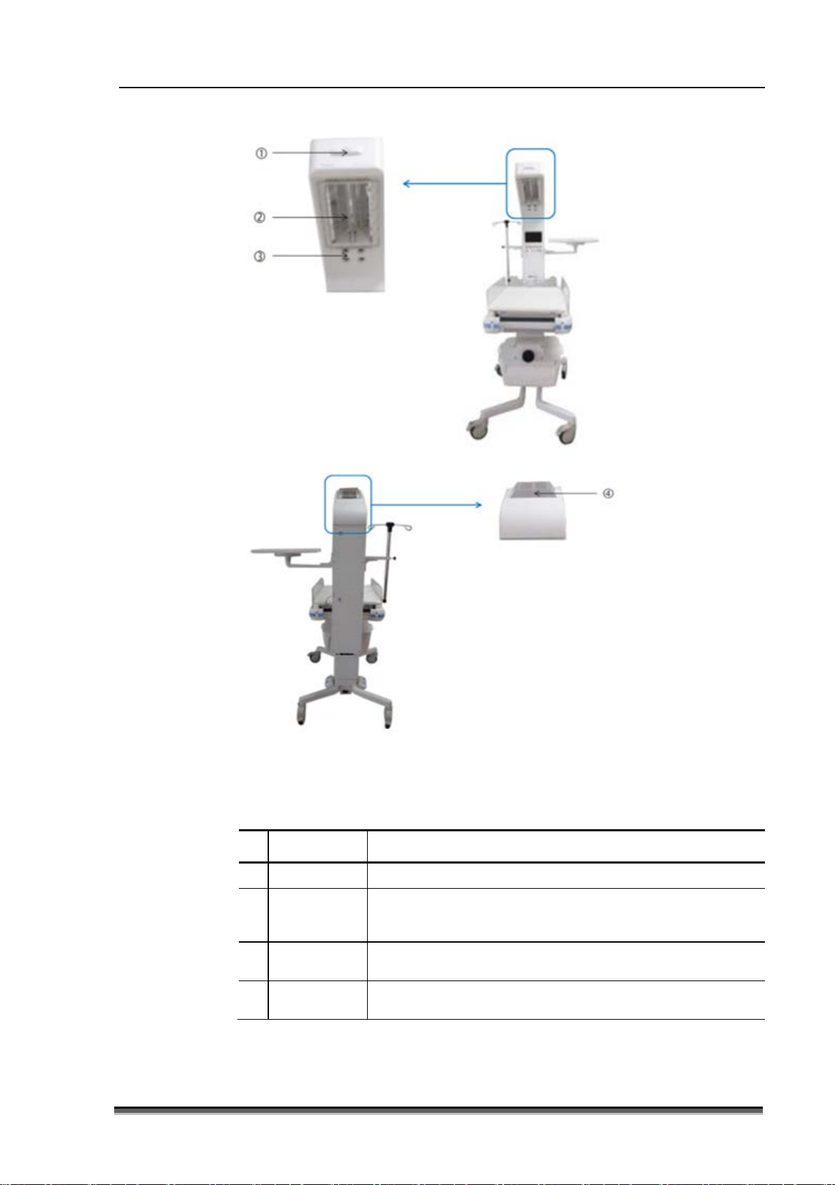
1.5 Description of System components
①
②
③
④
Figure1-3: System components
Name Description
Head
up to 90° to left and right each and totally 180°.
operate BT-550 inside. T
Column
power supply part, display and user interface.
The IV pole and plate for auxiliary equipment attached on the
Supporting the whole BT-550 system. Basic stand has fixed
height. Height adjustable stand is available as option.
Stand
It has equipped with caster to move the BT-550 easily and can be
fitted with drawer and bed tilting mechanism when options are
selected.
patient from falling off the mattress. X-ray cassette tray is located
Bed
under the bed for X-ray procedure. Weighing scale plate can be
placed beneath the mattress as option.
Protective barriers can be opened or removed from the bed for
Page 17
BT-550 Operation manual
16
P/N : 550-ENG-OPM-EUR-R01
Bistos Co., Ltd.
2018.03
Examination
lamp
Ventilation
hole
Figure1-4: Head
①
②
③
④
Name Description
Alarm light Flashing red light in alarm status
Heat source
Composed with heating element, reflecting plate and
protection guard to prevent touch the heating element
Provide added illumination of the mattress area
To ventilate the heated air around the heating element
Page 18
BT-550 Operation manual
17
P/N : 550-ENG-OPM-EUR-R01
Bistos Co., Ltd.
2018.03
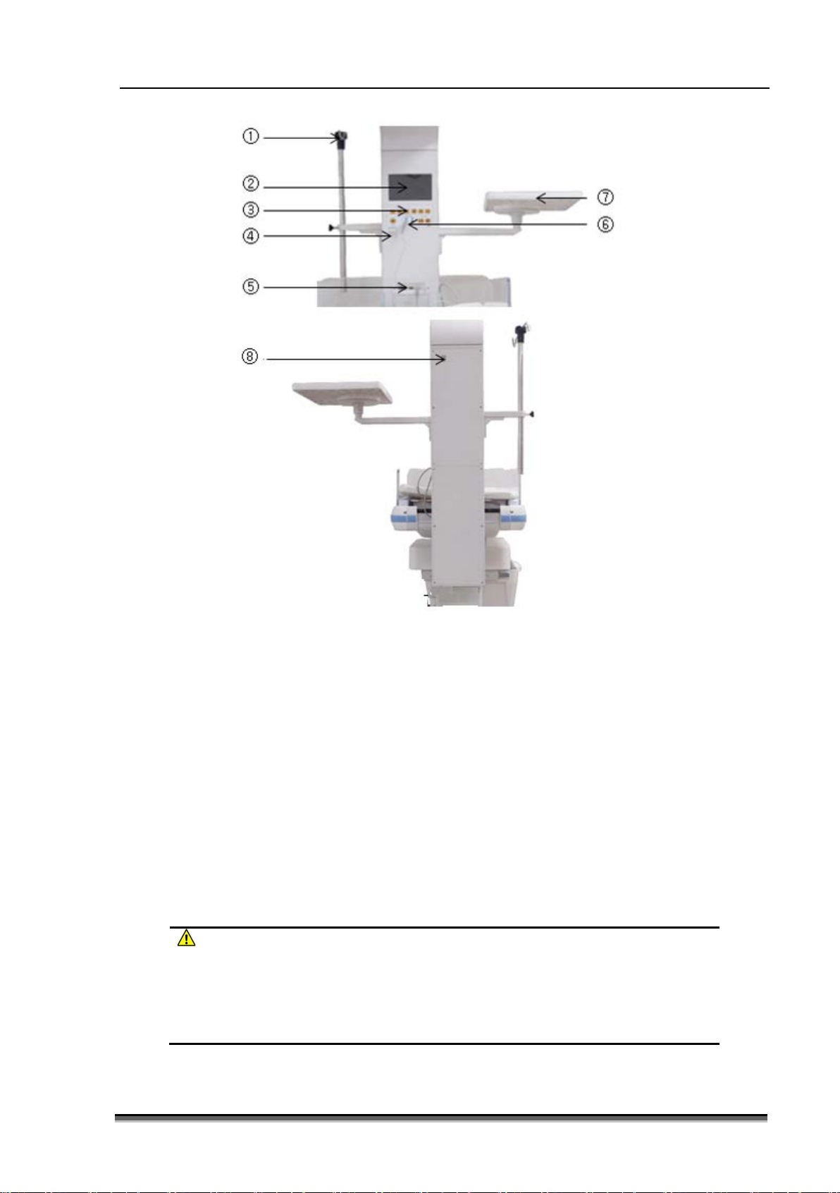
WARNING
The maximum permitted load of IV pole is 5 kg. Do not hang heavy object on
place heavy object on the plate.
Figure1-5: Column
① IV Pole
②
Display LCD
③ B
uttons
④
Power switch
⑤ C
onnector for SpO2 sensor and weighing scale
⑥
Connector for Skin temperature sensor
⑦ P
late for auxiliary equipment (IV Plate)
⑧
Speaker
the pole.
The maximum permitted load of plate for auxiliary equipment is 11 kg. Do not
Page 19

BT-550 Operation manual
18
P/N : 550-ENG-OPM-EUR-R01
Bistos Co., Ltd.
2018.03
WARNING
Do not place heavy objects on the X-ray cassette tray to prevent the device
heavy object on the tray.
Mattress ② X-ray cassette tray
①
Bed tilting mechanism ④ Tilting handle
③
Protective barriers ⑥ Weighing scale
⑤
Figure1-6 : Bassinet
falling down.
Do not place any object under the bed while taking the X-ray radiation.
Do not place infant on the X-ray cassette tray directly.
Do not move the infant warmer while X-ray cassette tray expelled.
The maximum permitted load of X-ray cassette tray is 1.5 kg. Do not place
Page 20

BT-550 Operation manual
19
P/N : 550-ENG-OPM-EUR-R01
Bistos Co., Ltd.
2018.03
WARNING
Do not place any items taller than the caster diameter of device to prevent any
the drawer.
Foot switch ② Drawer
①
AC power socket inlet ④ Caster
③
Figure 1-7: Stand part (Height adjustable stand)
disturbance of stability of stand and damage to the device
Keep vacant surrounding stand about 30 cm.
When adjusting the height of stand, place one hand on the infant warmer to
keep the balance of operator.
Be sure that auxiliary equipment or items are removed from the moving path
when adjusting the height of stand. Before adjusting the height, secure the safe
of infant and other connections.
The maximum permitted load of drawer is 10 kg. Do not place heavy object in
Page 21

BT-550 Operation manual
20
P/N : 550-ENG-OPM-EUR-R01
Bistos Co., Ltd.
2018.03
1.6 Understanding the display
Figure 1-8: Display when SpO2 option not installed
Figure 1-9: Display when SpO
option installed
2
① Measured temperature ② Set temperature
③ Selected operation mode ④ Alarm mute indicator
⑤ Examination lamp status indicator ⑥ Weight measured
⑦ APGAR timer ⑧ Current time
⑨ Heater power output indicator ⑩ Blood oxygen saturation, pulse rate
⑪ Photo plethysmograph and Signal IQ
®
(Signal Identification and Quality indicator)
Page 22

BT-550 Operation manual
21
P/N : 550-ENG-OPM-EUR-R01
Bistos Co., Ltd.
2018.03
Button for increment of temperature set value in
Button for decrement of temperature set value in
Alarm mute button. Push the button makes the
Button for lamp control. Lamp brightness changed
Button for set-up. Press this button to enter set-up
Button for APGAR Timer Start and Stop.
Figure1-10 Buttons
1.7 Buttons
Button Name Description
[MODE] Button for mode selection.
[UP]
baby mode and heater output in manual mode. And
can be used to move cursor upward or change the
set value in setting mode.
[DOWN]
baby mode and heater output in manual mode. And
can be used to move cursor downward or change
the set value in setting mode.
[ALARM
MUTE]
[LAMP]
audible alarm muted for about 5, 10, 15 minutes.
The red LED lighted when alarm muted.
in Low Medium High OFF sequence when
press the button.
[ZERO] Button to set the scale to zero.
[SETUP]
[APGAR*]
menu
*The APGAR timer provides tones at 1, 5 and 10 mins set
intervals to prompt the assessment on infants nursed
under the BT-550 infant warmer.
Page 23

BT-550 Operation manual
22
P/N : 550-ENG-OPM-EUR-R01
Bistos Co., Ltd.
2018.03
[APGAR
RESET]
Skin
temperature
sensor
connectors
Power
switch
Button for APGAR Timer Reset.
S1 : The first sensor to be attached to the abdomen
of infant (The heater power in baby mode is
controlled by the temperature measure from S1.)
S2 : The second sensor to be attached to the foot or
ear lobe of infant
A switch that serves to change between the on state
and the off state.
Page 24

BT-550 Operation manual
23
P/N : 550-ENG-OPM-EUR-R01
Bistos Co., Ltd.
2018.03
Figure
Description
POWER Fail
in white and red and audio alarm stays for 10
Figure1-12 : Sensor Disable
Sensor Disable
Figure1-14 : S2 Temp Error
Skin Temp high & low (for S1 and S2 sensor)
High Temperature: Alarm activated when the
Baby Check
In manual mode, the alarm activated after 12
15 minutes.
Figure1-16 : Head Rotation
Head Rotation
degree, the heater output reduced to 0% and
1.8 Alarm and warning indication
Figure1-11 : POWER Fail
Figure1-13 : S1 Temp Error
• When the supply power are interrupted the
‘POWER FAIL’ warning message are displayed
minutes
• Alarms are activated when skin temperature
sensor did not connect to S1 connector.
•
measured temperature is higher than set
temperature value by 1.0
℃ in baby mode or
38 ℃ in manual mode.
• Low temperature: Alarm activated when the
measured temperature is lower than set
temperature value by 1.0 ℃ in baby mode or
30 ℃ in manual mode.
Figure1-15 : Baby Check
•
minutes and the heater output reduced to
25 % after 15 minutes.
• In baby mode, the heater output set to
100 %, the alarm activated after 12 minutes
and the heater output reduced to 25 % after
• When the head is rotated more than 20
alarm activated.
Page 25

BT-550 Operation manual
24
P/N : 550-ENG-OPM-EUR-R01
Bistos Co., Ltd.
2018.03
Masimo Check Alarm
Alarm message
Situation
Open LEDs
LED opened
Shorted LEDs
LED shorted
Interference detected
Interference between
detector
Low SpO2
Measured SpO2 value is
setting
No cable
SpO2 cable was not
connected
Sensor off patient
Sensor was not
connected to the patient
Unrecognized sensor
The system cannot
recognize the sensor
Bad sensor ID offset
Not supported sensor
connected
Shorted detector
The detector diode
shorted
High pulse rate
Measured pulse rate is
setting
Low pulse rate
Measured pulse rate is
setting
No adhesive sensor
Not supported adhesive
sensor connected
No sensor connected
Too much ambient
light Low perfusion
Perfusion index is low
Low signal IQ
Signal IQ® is low
Masimo board failure
Masimo board failure and
failure code
Diagnostic failure
Diagnostic failure and
failure code
PROCAL FAILURE
ProCal failure
message pop-up displayed.
The following operation of device considered as fall back mode (mode of
Baby check
• Alarm will be activated upon following
situations:
Figure1-17: Masimo Check Alarm
Figure 1-18 Masimo Alarm message
transmitting LED and
lower than low limit
higher than high limit
lower than low limit
CAUTION
FALL BACK Mode
operation (or state) into which the Physiological Closed Loop Control System)
transitions when the PCLC (Physiological Closed Loop Controller) stops operating
due to detection of a fault).
Sensor disable
Skin temperature high/Low
Head rotation
• To see the alarm situation pressing down
the [ALARM MUTE] button until the
Page 26

BT-550 Operation manual
25
P/N : 550-ENG-OPM-EUR-R01
Bistos Co., Ltd.
2018.03
1.9 Essential performance
1) Accuracy of baby mode operation
The temperature as measured by the skin temperature sensor shall not differ from the control
temperature by more than 0.5 ℃,
2) Generation of visual and audible alarm
After steady temperature condition have been achieved, any sensed temperature deviation exceeding
±1°C compared with the control temperature shall cause an auditory and visual alarms to operate, and
the infant radiant warmer heater shall off when the sensed temperature exceeds the control
temperature by 1℃.
Page 27

BT-550 Operation manual
26
P/N : 550-ENG-OPM-EUR-R01
Bistos Co., Ltd.
2018.03
CAUTION
2 Operation of BT-550
2.1 Precautions
Use the BT-550 in the environment temperature 18 ~ 30 ℃ and humidity 0 ~
95%(non-condensing).
Be sure the power cord securely connected.
Do not connect several cords to one socket outlet.
Place the device on the flat floor.
Do not use the power cord which can cause the electromagnetic noise
Avoid the impact on the device.
Use the device in the place free from dust or flammable agent
Be sure to lock the caster before use.
The device shall be used only by appropriately trained personnel and under the
direction of qualified medical personnel who are familiar with currently known
risks and benefits of infant warmer use.
BT-550 should not be used adjacent to or stack with other equipment.
The AC power plug is a means to isolate its circuits electrically from the supply
mains on all poles simultaneously. Do not place the device in an area when there
is difficult to disconnect from the supply mains.
To avoid overheating or underheating, observe the infant constantly and monitor
the temperature using the skin temperature sensor supplied with the equipment
or other electronic thermometer. It is important to note that the skin temperature
alarms are not functional during manual operation. Therefore, the operator
should use baby mode whenever possible.
Page 28

BT-550 Operation manual
27
P/N : 550-ENG-OPM-EUR-R01
Bistos Co., Ltd.
2018.03
2.2 Assembling BT-550
2.2.1 Repositioning the column
Figure 2-1: Repositioning the Column (1)
1. Remove the package.
2. Remove the four M6X25 Hexagon head bolt (number ② in figure) from column (hold the
column securely to prevent declining) with 5 mm hexagon wrench enclosed.
3. Remove the six M4x8 machine screws (number ③ in figure) and detach the back cover
(number ④ in figure) from column.
Page 29

BT-550 Operation manual
28
P/N : 550-ENG-OPM-EUR-R01
Bistos Co., Ltd.
2018.03
Figure2-2: Repositioning the column (2)
1. Push up the column and align with the fixing hole as indicated in the figure with red arrow
2. Fix with four M6x15 bolts (number ② in figure) which removed above procedure. Hold
column tightly until bolting finished to prevent fall down.
3. Replace the back cover (number ④ in figure) and fix with six M4X8 (number ③ in figure)
which removed above procedure.
4. Detach the fixing bracket from device by loosening the M6x25 9number ⑤ in figure).
Page 30

BT-550 Operation manual
29
P/N : 550-ENG-OPM-EUR-R01
Bistos Co., Ltd.
2018.03
Figure2-3: Repositioning the column (3)
The assembling position is different for standard configuration and full option configuration. Be sure to
fixing on the right position depending on the options.
Page 31

BT-550 Operation manual
30
P/N : 550-ENG-OPM-EUR-R01
Bistos Co., Ltd.
2018.03
2.2.2 Installing the IV pole to column (Option)
Figure2-4 : Installing IV pole
1. Put the lower damper (number ⑤ in figure) to the lower part of column rail.
2. Slip-in the two joint nuts (number ⑥ in figure) to the column rail above the lower damper.
3. Put the upper damper (number ③ in figure) to the upper part of column rail.
4. Fix the IV frame to column with two M6X15 (number ④ in figure) using enclosed hexagon 5
mm wrench.
5. Put the IV pole (number ① in figure) to IV frame and fix it with turning screw located in the
frame.
2.2.3 Installing the plate for auxiliary equipment to column (Option)
Page 32

BT-550 Operation manual
31
P/N : 550-ENG-OPM-EUR-R01
Bistos Co., Ltd.
2018.03
Figure2-5 : Installing plate for auxiliary equipment to column
1. Put the lower damper (number
2. Slip-in the two joint nuts (number
3. Put the upper damper (number
4. Fix the plate frame (number
using enclosed hexagon 5 mm wrench.
5. Fix the plate (number
① in figure) to plate flame with M5X15 hexagon head bolt using
enclosed hexagon 4 mm wrench.
2.3 Separating barriers
⑥ in figure) to the lower part of column rail.
⑤ in figure) to the column rail above the lower damper.
④ in figure) to the upper part of column rail.
② in figure) to column with two M6X15 (number 7 in figure)
Page 33

BT-550 Operation manual
32
P/N : 550-ENG-OPM-EUR-R01
Bistos Co., Ltd.
2018.03
WARNING
Do always for both ends together.
Keep the barrier latched always when possible.
Pull the barrier upward.
Decline the barrier backward and
detach upper locking pin.
Pull the barrier upward again and
detach lower locking pin.
Figure2-6 : Separating barriers
Regularly inspect the latches and closing devices of barriers to prevent the
infant falling out.
2.4 Bed tilting mechanism
Page 34

BT-550 Operation manual
33
P/N : 550-ENG-OPM-EUR-R01
Bistos Co., Ltd.
2018.03
Figure 2-7: Tilting handle
Do not press a bed with over pressure.
Do not turn the tilting handle with excessive force.
WARNING
Tilting of the mattress from its horizontal position relative to the infant warmer
an increase in infant temperature to dangerous levels.
The bed can tilted for 15°±2° to
backward or forward
CAUTION
heater can affect the performance of the infant warmer.
The accessories such as phototherapy or heated mattresses, or sunlight can cause
2.5 Skin temperature sensor
Page 35

BT-550 Operation manual
34
P/N : 550-ENG-OPM-EUR-R01
Bistos Co., Ltd.
2018.03
WARNING
Never try to move the device while the infant placed in the device.
the infant warmer.
• Before adhere the sensor to infant, hold the metallic part of sensor
end with fingers and check the temperature display relevant to
body temperature.
• Attach the S1 sensor to the abdomen and S2 sensor (option) to the
foot or ear lobe of infant using adhesive tape.
• The temperature measurement automatically started when power
on the device if the sensor is connected.
• Sensor is reusable. After use clean and store according to the
instructions described in section 4 of this manual.
Figure 2-8
Skin temperature sensor
The skin temperature sensor should be contacted to bare skin of infant for correct
measurement. Otherwise the temperature can increase to dangerous levels.
Frequently check whether the sensor contacted correctly to infant’s skin and
overheat.
Do not pull the wire of sensor. Remove the sensor by detach the adhesive tape.
Independent monitoring of the temperature of the infant by the operator is
essential. Monitor the temperature of infant regularly with auxiliary thermometer.
The infant warmer cannot differentiate between an increase in core temperature
with a cold skin (fever) and a low core and skin temperature (hypothermia).
Monitor the temperature of infant regularly with auxiliary thermometer.
The rectal temperatures are not appropriate for controlling the heater output of
2.6 Prepare to use
Page 36

BT-550 Operation manual
35
P/N : 550-ENG-OPM-EUR-R01
Bistos Co., Ltd.
2018.03
1. Connect the power cord to the power
2. Connect all cables and sensors to the
3. Turn on the power and check
5. When the power on, BT-550 start to
WARNING
Securely latch the power cord to prevent the power cord unintentionally detached
body in force. Check the shape, position and direction of connector.
Figure 2-9: Power cord
Figure 2-10: Product logo and initial screen
inlet connector of BT-550. In the
basic configuration, the power inlet
connector is located under the
column. In the full option
configuration, it is located behind the
stand assay. Clip the power cord to
prevent detached unintentionally.
relevant connectors. Be sure to
connect the cables and sensors to the
right connectors.
whether the product logo and initial
screen is displayed.
4. After booting sequence finished, the
main screen will be displayed. Check
whether all the relevant information
are displayed
operate in ‘pre warm’ mode with
100% heater output (28
㎽/㎠±20%)
for five minutes. After then the
heater output decrease to 60% for 10
minutes and further decrease to 25%.
from power inlet connector.
Do not pull or push when connecting or disconnecting connector from or to main
2.7 Operation
Page 37

BT-550 Operation manual
36
P/N : 550-ENG-OPM-EUR-R01
Bistos Co., Ltd.
2018.03
Infant warmer can increase the patient’s insensible water loss. Keep the water
Use the infant warmer in the place where the air flow is slower than 0.3 m/s.
(0) Power On
When the power switch turned on, initial logo screen displayed.
(1) Measuring the skin temperature of infant
The BT-550 start to measure the skin temperature of infant as the power switched on. When
the skin temperature sensor does not connected to the connector in baby mode, sensor
disable message displayed and audible alarm activated.
(2) Mode selection
Baby Mode – Heater output controlled automatically by measured skin temperature
• Select Baby Mode by pressing [MODE] button.
• Set the desired temperature by pressing [INCREASE] or [DECREASE] button. The heater
output controlled according to the measured skin temperature of S1 skin temperature
sensor.
• ‘Baby Check’ message will displayed and alarm activated after 12 minutes if the heater
output stay 100 % and the output will be decreased to 25 % after 3 minutes when no
button operation detected.
Manual Mode – Heater output controlled manually
• Select Manual Mode by pressing [MODE] button.
• Set the desired heater output by pressing [INCREASE] or [DECREASE] button.
• ‘Baby Check’ message will displayed and alarm activated if the device stay in Manual
Mode more than 12 minutes and the power will be decreased to 25 % after 3 minutes
when no button operation detected.
WARNING
balance of patient carefully.
Do not place any objects in the infant warmer to prevent the objects getting hot.
The objects can disturb the transfer of heat to patient.
Heater, lamp and adjacent areas are very hot. Do not touch these parts with bare
hand.
Infant warmer does not adjust for patient temperature in Pre-warm Mode. The
mode shall be changed to Manual Mode or Baby mode immediately when the
patient is placed on the device.
The skin temperature of infant can be affected by environment such as strong air
flow, direct sunlight. It is always recommended to use infant warmer in Baby
Mode as possible.
(3) Weighing scale(Option)
Page 38

BT-550 Operation manual
37
P/N : 550-ENG-OPM-EUR-R01
Bistos Co., Ltd.
2018.03
Parameters
Default value
Control temperature in Baby Mode
36 ℃
Heater output in Manual Mode
50 %
Temperature unit
Weight Unit
Kg
Alarm mute period
5 minutes
Alarm sound level
Max
Pulse rate beep volume
3 steps
SpO2 algorithm mode
Normal sensitivity
SpO2 alarm delay
0 second
Average time
2-4 seconds
SpO2 low limit
85
Pulse rate high limit
200
Pulse rate low limit
100
Scale calibration value
Disabled
Weighing scale is option. The infant warmer measures the weight of infant automatically when
the weighing plate is connected to the infant warmer. Press [ZERO] button to set the scale to
zero.
(4) SpO2 and pulse rate (Option)
The SpO2 option is disabled when delivered. The enable/disable of SpO2 option can be changed
in Service Mode. Press the following buttons in sequence to enter Service Mode: [UP]
[DOWN] [UP] [DOWN] [SETUP] [APGAR] [APGAR RESET]. Change the SpO
Option from DIS to EN. Select [EXIT] using [UP] or [DOWN] button and press [SETUP] button.
2
The SpO
function only activated when the SpO2 module connected to BT-550. The
2
measurement is started when the sensor is attached to infant’s index finger or other part (such
as toe, ear lobe etc.). Use site appropriate according to each sensor’s individual direction for
use.
(5) APGAR Timer
Press [APGAR] button to start the APGAR timer. Indicating sound will be heard on 1 minute, 5
minutes and 10 minutes. Press [APGAR] button to mute the timer. To reset the timer, press
[APGAR RESET] button.
(6) Examination lamp
You can control the brightness of examination lamp. Press the [LAMP] button to change the
lamp brightness from OFF to low, mid and high. Press the [LAMP] button again to OFF the
lamp.
(7) Setup
Below is the initial factory setting of parameters;
In Setup Mode following parameters can be changed.
℃
Page 39

BT-550 Operation manual
38
P/N : 550-ENG-OPM-EUR-R01
Bistos Co., Ltd.
2018.03
Category
Parameter
Description
Selection
Time
To set the current time
AM/PM, Hour and minutes
Temp. Unit
To select the temperature
unit
(Celsius)/ ℉(Fahrenheit)
Weight Unit
To select the weight unit
kg(kilogram)/lb(pound)
Default set
All parameters are reset to factory setting
Mute period
Alarm paused time
5/10/15 minutes
PR beep
volume
Pulse rate volume sound
0 ~ 5 steps
SpO2 alarm
delay
SpO2 alarm delay time setup
0/5/10/15 seconds
Alarm test
To check alarm work correctly. The audio and visual alarm
audible and visible status before operating.
Algorithm
SpO2 measuring algorithm
Normal sensitivity,
Detection)
Normal
This selection provides the best combination of sensitivity
for the majority of patients
Maximum
This selection should be reserved for the sickest patients,
continuous.
APOD®
This mode is the least sensitive in picking up a reading on
(pediatric, combative, etc.)
FastSat®
Enable rapid tracking of
ON/OFF
automatically activated
Average
Set the time to average
2-4/4-6/8/10/12/14/16
seconds
SpO2 alarm
limt L
SpO2 low alarm limit. Alarm activated when measured
value are lower than this limit. Cannot be set below 85.
PR alarm limt
Pulse rate low and high alarm limit. Alarm activated when
10 lower from high limit setting.
System
Alarm
℃
can be generated by ON the alarm test in Setup mode.
The operator should be test the alarm system normality of
SpO2
mode
sensitivity
sensitivity
(Adaptive
Probe Off
Detection)
selection
Maximum sensitivity,
APOD(Adaptive Probe Off
and probe-off detection performance and is recommended
where obtaining a reading is most difficult. Maximum
sensitivity is designed to interpret and display data for
even the weakest of signals, and is recommended during
procedures and when clinician and patient contact is
patients with low perfusion but has the best detection for
probe-off conditions. This mode is useful for patients that
are at particular risk of sensor becoming detached
arterial oxygen saturation
changes
When the average time set
to 2-4 or 4-6, the FastSat
®
is
H, L
measured value are lower or higher than this limit. High
limit can be set to 50 -240 and low setting value should be
more than 10 higher from low limit setting. Low limit can
be set to 40-230 and high setting value should be less than
(8) Power Off
Page 40

BT-550 Operation manual
39
P/N : 550-ENG-OPM-EUR-R01
Bistos Co., Ltd.
2018.03
WARNING
SpO2 monitor of BT-550 must be operated by qualified personnel only.
Measure the oximeter’s leakage current whenever an external device is connected
Turn the power off after using the device. When the device expected do not used for a while,
then unplug the power cord from socket outlet.
2.8 SpO2 Monitor(option)
This symbol means that the Masimo product inside.
BT-550 uses the Masimo SpO2 oximetry to monitor the oxygen saturation in the blood. You can find
the detailed Masimo product information below.
Patent information for Masimo product can be found at www.masimo.com/patents.htm.
“Possession or purchase of this device does not convey any express or implied license to use the device
with unauthorized sensors or cables which would, alone or in combination with this device, fall within
the scope of one or more the patents relating to this device”
Do not use the MS board pulse oximeter in the presence of flammable anesthetics
or other flammable substance in combination with air, oxygen-enriched
environments, or nitrous oxide.
A pulse oximeter should NOT be used as an apnea monitor.
Pulse rate measurement is based on the optical detection of a peripheral flow
pulse and therefore may not detect certain arrhythmias. The pulse oximeter
should not be used as a replacement or substitute for ECG based arrhythmia
analysis.
A pulse oximeter should be considered an early warning device. As a trend
towards patient deoxygenation is indicated, blood samples should be analyzed by
a laboratory co-oximeter to completely understand the patient’s condition.
If an alarm condition (other than exceptions listed herein) occurs while the alarm
silence period is set to off, the only alarm indications will be visual displays and
symbols related to the alarm condition.
The MS board pulse oximeter is to be operated by qualifier personnel only. These
manual, accessory directions for use, all precautionary information, and
specifications should be read before use.
Do not remove the monitor cover except to replace the battery. An operator may
only perform maintenance procedures specifically described in this manual. Refer
servicing to Masimo in repair of this equipment.
Page 41

BT-550 Operation manual
40
P/N : 550-ENG-OPM-EUR-R01
Bistos Co., Ltd.
2018.03
to the serial port. Leakage current must not exceed 100 microamperes.
CAUTION
Connect the oximeter only to a three-wire, grounded, hospital-grade receptacle.
The three-conducting plug must be inserted into a properly wired three-wire
receptacle is not available, a qualified electrician must install one in accordance
with the governing electrical code.
Do not under any circumstances remove the grounding conductor from the power
plug.
Do not use extension cords or adapters of any type. The power cord and plug must
be intact and undamaged.
If there is any doubt about the integrity of the protective earth conductor
arrangement, operate the oximeter on internal battery power until AC power
supply protective conductor is fully functional.
To ensure patient electrical isolation, connect only to other equipment with
electrically isolated circuits.
Do not connect to an electrical outlet controlled by a wall switch or dimmer.
As with all medical equipment, carefully route patient cabling to reduce the
possibility of patient entanglement or strangulation.
Do not place the monitor or external power supply in any position that might
cause it to fall on the patient. Do not lift the monitor by the power supply cord or
patient cable; use only the handle on the monitor.
Carboxyhemoglobin may erroneously increase readings. The level of increase in
approximately equal to the amount of carboxyhemoglobin present. Dyes, or any
substance containing dyes, that change usual arterial pigmentation may cause
erroneous readings.
Do not use the MS board pulse oximeter or Masimo oximetry sensors during
magnetic resonance imaging (MRI) scanning. Induced current could potentially
cause burns. The MS board pulse oximeter may affect the MRI image, and the MRI
unit may affect the accuracy of the oximetry measurements.
Consult IEC 60601-1 for system interconnection guidance. The specific
requirements for system interconnection are dependent upon the device
connected to the MS board pulse oximeter and the relative locations of each
device from the patients, and the relative location of the connected device to the
medically used room containing the MS board pulse oximeter. In all circumstance
the MS board pulse oximeter must be connected to a grounded AC power supply.
The MS board pulse oximeter is referred to as an IEC 60601 F device in the
summary of situation table contained in IEC 60601-1.
Page 42

BT-550 Operation manual
41
P/N : 550-ENG-OPM-EUR-R01
Bistos Co., Ltd.
2018.03
Do not autoclave or gas sterilize this oximeter.
may tend to read in the low to mid 80s. When elevated levels of MetHb
Do not soak or immerse the monitor in any liquid.
Use the cleaning solution sparingly. Excessive solution can flow into the monitor
and cause damage to internal components.
Do not touch, press, or rub the display panels with abrasive cleaning compounds,
instruments, brushes, rough-surface materials, or bring them into contact with
anything that could scratch the panel.
Do not use petroleum-based or acetone solutions, or other harsh solvents, to
clean the oximeter. These substances attach the device’s materials and device
failure can result.
Check alarm limits each time the MS board pulse oximeter is used to ensure that
they are appropriate for the patient being monitored.
If the accuracy of any measurement does not seem reasonable, first check the
patient’s vital signs by alternate means and the check the MS board pulse
oximeter for proper functioning.
Inaccurate measurements may be caused by
Incorrect sensor application or use
Significant levels of dysfunctional hemoglobin. (e.g., carboxyhemoglobin or
methemoglobin)
Intravascular dyes such as indocyanine green or methylene blue.
Interfering Substances: Dyes, Nail polish or any substance containing dyes,
that change usual blood pigmentation may cause erroneous readings.
Pulse rate measurement is based on the optical detection of a peripheral flow
pulse and therefore may not detect certain arrhythmias. The pulse oximeter
should not be used as a replacement or substitute for ECG based arrhythmia
analysis.
Exposure to excessive illumination, such as surgical lamps (especially ones
with a xenon light source), bilirubin lamps, fluorescent lights, infrared heating
lamps, or direct sunlight (exposure to excessive illumination can be corrected
by covering the sensor with a dark or opaque material)
Excessive patient movement
SpO
is empirically calibrated to functional arterial oxygen saturation in
2
healthy adult volunteers with normal levels of carboxyhemoglobin (COHb)
and methemoglobin (MetHb). A pulse oximeter cannot measure elevated
levels of COHb or MetHb. Increase in either COHb or MetHb will affect the
accuracy of the SpO
For increased COHb: COHb levels above normal tend to increase the
level of SpO
of COHb that is present. High levels of COHb may occur with a seemingly
normal SpO
analysis (CO-Oximetry) of a blood sample should be performed.
For increased MetHb: the SpO
up to approximately 10% to 15%. At higher levels of MetHb, the SpO
measurement.
2
. The level of increase is approximately equal to the amount
2
. When elevated levels of COHb are suspected, laboratory
2
may be decreased by levels of MetHb of
2
2
Page 43

BT-550 Operation manual
42
P/N : 550-ENG-OPM-EUR-R01
Bistos Co., Ltd.
2018.03
are suspected, laboratory analysis (CO-Oximetry) of a blood sample
- The patient is in cardiac arrest or is in shock.
should be performed.
Venous congestion may cause under reading of actual arterial oxygen
saturation. Therefore, assure proper venous outflow from monitored site.
Sensor should not be below heart level (e.g. sensor on hand of a patient in a
bed with arm dangling to the floor).
Venous pulsation may cause erroneous low readings (e.g. tricuspid value
regurgitation).
Patient suffers from abnormal pulse rhythm.
The pulsations from intra-aortic balloon support can be additive to the pulse
rate on the oximeter pulse rate display. Verify patient’s pulse rate against the
ECG heart rate.
Use only Masimo approved accessories.
Motion artifact man lead to inaccurate measurements.
Elevated levels of Total Bilirubin may lead to inaccurate SpO2 measurements.
With very low perfusion at the monitored site, the readings may read lower
than core arterial oxygen saturation.
Do not expose the Pulse CO-Oximeter to excessive moisture such as direct
exposure to rain. Excessive moisture can cause the Pulse CO-Oximeter to
perform inaccurately or fail.
Do not immerse the sensor or patient cable in water or, solvents, or cleaning
solutions (The sensors and connectors are not waterproof).
Placement of a sensor on an extremity with a blood pressure cuff, arterial
catheter, or intravascular line.
The MS board can be used during defibrillation, but the readings may be
inaccurate for a short time.
Loss of pulse signal can occur in any of the following situation
- The sensor is too tight
- There is excessive illumination from light sources such as a surgical lamp, a
bilirubin lamp, or sunlight.
- A blood pressure cuff is inflated on the same extremity as the one with a
SpO2 sensor attached
- The patient has hypotension, severe vasoconstriction, severe anemia, or
hypothermia.
- There is arterial occlusion proximal to the sensor.
Pulse oximetry is a continuous and non-invasive method of measuring the level of arterial oxygen
saturation in blood. The measurement is taken by placing a sensor on a patient, usually on the fingertip
for adults, and the hand or foot for neonates. The sensor is connected to the pulse oximetry
instrument with a patient cable. The sensor collects signal data from the patient and sends it to the
instrument. The instrument displays the calculated data in two ways: 1) as a percent value for arterial
oxygen saturation (SpO
), and, 2) as a pulse rate (PR).
2
Page 44

BT-550 Operation manual
43
P/N : 550-ENG-OPM-EUR-R01
Bistos Co., Ltd.
2018.03
- Operating Principles
The BT-550 MS board pulse oximeter is based on three principles:
1. Oxyhemoglobin and deoxyhemoglobin differ in their absorption of red and infrared light
(spectrophotometry).
2. The volume of arterial blood in tissue and the light absorbed by the blood changes during
the pulse (plethysmography).
3. Arterio-venous shunting is highly variable and that fluctuating absorbance by venous blood
is a major component of noise during the pulse.
The pulse oximeter of BT-550 as well as traditional pulse oximetry determines SpO
by passing red and
2
infrared light into a capillary bed and measuring changes in light absorption during the pulsatile cycle.
Red and infrared light-emitting diodes (LEDs) in oximetry sensors serve as the light sources, a
photodiode serves as the photodetector.
Traditional pulse oximetry assumes that all pulsations in the light absorbance signal are caused by
oscillations in the arterial blood volume. This assumes that the blood flow in the region of the sensor
passes entirely through the capillary bed rather than through any arterio-venous shunts. The
traditional pulse oximeter calculates the ratio of pulsatile absorbance (AC) to the mean absorbance(DC)
at each of two wavelengths, 660 nm and 905 nm:
S(660) = AC(660) / DC(660)
S(905) = AC(905) / DC(905)
The oximeter then calculates the ratio of these two arterial pulse-added absorbance signals:
R = S(660) / S(905)
This value of R is used to find the saturation SpO
in a look-up table built into the oximeter’s software.
2
The values in the look-up table are based upon human blood studies against a laboratory co-oximeter
on healthy adult volunteers in induced hypoxia studies.
The BT-550 MS board pulse oximeter assumes that arterio-venous shunting is highly variable and that
fluctuating absorbance by venous blood is the major components of noise during the pulse. BT-550 MS
board decomposes S(660) and S(905) into an arterial signal plus a noise component and calculates the
ratio of the arterial signals without the noise:
S(660) = S1 + N1
S(905) = S2 + N2
R = S1 / S2
Again, R is the ratio of two arterial pulse-added absorbance signals and its value is used to find the
saturation SpO
empirically derived equation are based upon human blood studies against a laboratory co-oximeter on
healthy adult volunteers in induced hypoxia studies.
in an empirically derived equation into the oximeter’s software. The values in the
2
Page 45

BT-550 Operation manual
44
P/N : 550-ENG-OPM-EUR-R01
Bistos Co., Ltd.
2018.03
WARNING
The above equations are combined and a noise reference (N’) is determined:
N’ = S(660) – S(905) x R
If there is no noise N’ = 0: then S(660) = S(905) x R which is the same relationship for the traditional
pulse oximeter.
The equation for the noise reference is based on the value of R, the value being sought to determine
the SpO
. The MS board software sweeps through possible values of R that corresponds to SpO2 values
2
between 1% and 100% and generates an N’ value for each of these R-values. The S(660) and S(905)
signals are processed with each possible N’ noise reference through an adaptive correlation canceler
(ACC) which yields an output power for each possible value of R (i.e., each possible SpO
from 1% to
2
100%). The result is a Discrete Saturation Transform (DST™) plot of relative output power versus
possible SpO
value as shown in the following figure where R corresponds to SpO2 = 97%:
2
The DST plot has two peaks: the peak corresponding to the higher saturation is selected as the SpO
value. This entire sequence is repeated once every two seconds on the most recent four seconds of
raw data. The MS board SpO
saturation that is updated every two seconds.
- Grounding
Connect the oximeter only to a three-wire, grounded, hospital-grade receptacle. The three-conductor
plug must be inserted into a properly wired three-wire receptacle; if a three-wire receptacle is not
available, a qualified electrician must install one in accordance with the governing electrical code.
therefore corresponds to a running average of arterial hemoglobin
2
2
Page 46

BT-550 Operation manual
45
P/N : 550-ENG-OPM-EUR-R01
Bistos Co., Ltd.
2018.03
Do not under any circumstances remove the grounding conductor from the power
be intact and undamaged.
WARNING
Do not place the monitor or external power supply in any position that might
patient cable; use only the handle on the monitor.
plug.
Do not use extension cords or adapters of any type. The power cord and plug must
If there is any doubt about the integrity of the protective earth conductor arrangement, operate the
oximeter on internal battery power until the AC power supply protective conductor is fully functional.
- Patient Isolation
To ensure patient electrical isolation, connect only to other equipment with electronically isolated
circuits.
Note: Do not connect to an electrical outlet controlled by a wall switch or dimmer.
- Cabling entanglement/strangulation
As with all medical equipment, carefully route patient cabling to reduce the possibility of patient
entanglement or strangulation.
cause it to fall on the patient. Do not lift the monitor by the power supply cord or
- RS-232 & Alarms
RS-232 System Interconnection. Consult IEC-601-1-1 for system interconnection guidance. The specific
requirements for system interconnection are dependent upon the device connected to the MS board
pulse oximeter and the relative locations of each device from the patient, and the relative location of
the connected device to the medically used room containing the MS board pulse oximeter. In all
circumstance the MS board pulse oximeter must be connected to a grounded AC power supply. The MS
board pulse oximeter is referred to as an IEC 60601/F device in the summary of situations table
contained in IEC 60601-1-1.
Check alarm limits each time the MS board pulse oximeter is used to ensure that they are appropriate
for the patient being monitored.
Page 47

BT-550 Operation manual
46
P/N : 550-ENG-OPM-EUR-R01
Bistos Co., Ltd.
2018.03
WARNING
Pre-warm the infant before placing infant in the infant warmer under the direction
Do not leave an infant unattended under the infant warmer.
WARNING
Never move the infant warmer while an infant is placed.
The infant warmer should be carried by two persons.
3 Placing infant and moving BT-550
3.1 Placing infant
(1) Pre-warm infant warmer.
(2) Place the infant in the center of mattress.
(3) Attach the skin temperature sensor to the appropriate part such as abdomen with adhesive
tape.
(4) Select the operating mode and set the desired temperature or heater output according to the
selected mode.
of qualified medical personnel who are familiar with currently known risks and
benefits of infant warmer use.
3.2 Move the BT-550
3.2.1 Precautions
(1) Check whether an infant placed in the infant warmer mattress.
(2) Disconnect all cables from stand and remove unused accessories.
(3) For the height adjustable stand, adjust the height to lowest position.
(4) Place the power cord on the device to protect.
Push or pull to the direction along the longitudinal of stand to prevent
overbalancing.
Page 48

BT-550 Operation manual
47
P/N : 550-ENG-OPM-EUR-R01
Bistos Co., Ltd.
2018.03
Figure 2-11: Caster locks
WARNING
Always keep the caster locked for safety. When the infant warmer placed on the
inclined floor, do not leave the infant warmer unattended.
3.2.2 Stand caster lock
At least two casters should be locked
Caster unlocked
before using. To lock the caster,
depress the caster lock. To unlock the
caster, raise above the caster lock.
Caster locked
Page 49

BT-550 Operation manual
48
P/N : 550-ENG-OPM-EUR-R01
Bistos Co., Ltd.
2018.03
WARNING
Do not remove the covers of BT-550 yourself to avoid damage to the infant warmer
changed.
Do not use the conductive or flammable cleaning agent to avoid electric shock, fire
4 Maintenance and cleaning
4.1 Service policy
The repair of infant warmer should be performed qualified service personnel. Contact to Customer
Service Department of Bistos when the device fault or malfunctioning.
4.2 Maintenance
It is recommended to have a safety inspection every year regularly for the safe use of BT-550. Refer to
the service manual for the inspection items and method.
and unexpected electrical shock. Only qualified Bistos service engineer must repair
or replace components.
The life time of heater is about 5 000 hours. After this time the heater should be
4.3 Cleaning
Follow the instruction prior to clean the infant warmer.
Turn off the BT-550 and detach the power cord.
Detach all accessories from BT-550.
Cool down the BT-550 for about 30 minutes.
Use a clean gauze pad or lint-free cloth, lightly moistened with a water or mild detergent, to
wipe the surface of BT-550.
WARNING
or explosion.
Do not use spray type cleaning agent.
Do not scrub the display with rough or sharp objects.
Do not use steam to clean the infant warmer. Excessive steam can damage the
infant warmer.
Avoid using alcohol and strong detergent to bassinet made of acrylic.
Ensure no part of the warmer or accessories are immersed in any cleaning agents.
Page 50

BT-550 Operation manual
49
P/N : 550-ENG-OPM-EUR-R01
Bistos Co., Ltd.
2018.03
4.3.1 Skin sensor
- Clean the sensors with alcohol, or detergent or soap solution.
- Apply the cleaning solution with a clean cloth or sponge, and dry all surfaces after cleaning with a
clean soft cloth or paper towel.
CAUTION:
• Do not immerse, boil, autoclaves or gas sterilize the sensor.
• Avoid soaking in alcohols, strong detergents. Or highly alkaline solutions.
• Ensure the skin sensor is only removed from the controller by grasping the plug at the
front panel. Ensure excessive strain is not placed on the sensor lead either during use,
cleaning or inspection
4.3.2 SpO
sensor
2
- Clean the sensor by wiping it with a 70% isopropyl alcohol pad or mild detergent.
- Dry the sensor and cable with a clean cloth or dry gauze pad.
CAUTION:
• Do not immerse the connector of YI cable in any liquid solution.
• Do not sterilize by irradiation, steam, autoclave, Gluteraldehyde (Cidex) or ethylene
oxide.
• Carefully read 2.8 SpO2 Monitor(option) for proper use, cleaning or inspection
4.3.3 Mattress
- Clean the mattress with an approved and correctly diluted disinfectant-detergent solution, ensuring
the manufacturer’s directions for use of the cleaning agent are followed.
- Apply the cleaning solution with a clean cloth or sponge, and dry all surfaces after cleaning with a
clean soft cloth or paper towel.
Do not autoclaves or gas sterilize the mattress.
CAUTION:
Page 51

BT-550 Operation manual
50
P/N : 550-ENG-OPM-EUR-R01
Bistos Co., Ltd.
2018.03
WARNING
Do not attempt to open the covers, disassemble or modify the infant warmer
service engineer must repair or replace the infant warmer or components.
The infant warmer does not turned on
Check the power cord securely connected
Measured values are not displayed
Check the sensor cable or extension cable
Measured values are too high or low
Check the sensor correctly attached to
Alarm message
Alarm conditions
Power Fail
Power cord was not connected properly or power
Sensor Disable
Skin temperature sensor was not connected or
S1 (S2) Temp Low
Measured skin temperature is too low
S1 (S2) Temp High
Measured skin temperature is too high
Baby Check
Stay in the Manual Mode more than 12 minutes
Head Rotation
Masimo check Alarm
Refer to the table on page 18
5 Trouble shooting
5.1 General
except the qualified person. It may cause safety hazard. Only the qualified Bistos
Please check before contact to Customer Service Department of Bistos for following cases
to power consent
correctly connected to appropriate
connector.
5.2 Understanding alarm
The following alarms are displayed on the conditions of
does not supplied
measured temperature is too low
Check the sensor properly operating after
connecting the sensor.
patient.
For the weight, check the heavy objects
are placed while zero set or measuring.
Heater output remains 100 % in Baby Mode more
than 12 minutes
The head on infant warmer rotated more than 20°
Page 52

BT-550 Operation manual
51
P/N : 550-ENG-OPM-EUR-R01
Bistos Co., Ltd.
2018.03
The BT-550 is suitable for use in all
6 Manufacturer’s declaration on EMC
BT-550 needs special precautions regarding EMC (Electromagnetic compatibility) and needs to be
used according to the EMC information provided in this user manual. Wireless communications
equipment such as wireless home network devices, mobile phones, cordless telephones and their
base stations, walkie-talkies can affect the BT-550 and should be kept at least 1 m away from the
equipment.
6.1 Electromagnetic emissions
The BT-550 is intended for use in the electromagnetic environment specified below.
The customer or the user of the BT-550 should assure that it is used in such an environment.
Emissions test Compliance Electromagnetic environment - guidance
The BT-550 uses RF energy only for its internal
RF emissions
CISPR 11
Group 1
function. Therefore, its RF emissions are very
low and are not likely to cause any interference
in nearby electronic equipment.
RF emissions
CISPR 11
Harmonic emissions
IEC 61000-3-2
Voltage fluctuations /
flicker emissions
IEC 61000-3-3
Class A
Class A
Complies
establishments other than domestic, and may
be used in domestic establishments and those
directly connected to the public low-voltage
power supply network that supplies buildings
used for domestic purposes, provided the
following warning is heeded:
Warning: This BT-550 is intended for use by
healthcare professionals only. This equipment/
system may cause radio interference or may
disrupt the operation of nearby equipment. It
may be necessary to take mitigation measures,
such as re-orienting or relocating the BT-550 or
shielding the location.
Page 53

BT-550 Operation manual
52
P/N : 550-ENG-OPM-EUR-R01
Bistos Co., Ltd.
2018.03
The BT-550 is intended for use in an electromagnetic environment in which radiated RF
550 can help prevent
550 as recommended
Separation distance according to frequency of transmitter
0.01
0.1
1
10
100
For transmitters rated at a maximum output power not listed above, the recommended
maximum output power rating of the
NOTE 2) These guidelines may not apply in all situations. Electromagnetic propagation is
6.2 Recommended separation distances between portable and mobile RF communications
equipment and the BT-550
disturbances are controlled. The customer or the user of the BTelectromagnetic interference by maintaining a minimum distance between portable and
mobile RF communications equipment (transmitters) and the BTbelow, according to the maximum output power of the communications equipment.
Rated maximum
[m]
output power of
transmitter
[W]
150 kHz to 80 MHz
80 MHz to 800 MHz
800 MHz to 2.5 GHz
0.12 0.12 0.23
0.38 0.38 0.73
1.2 1.2 2.3
3.8 3.8 7.3
12 12 23
separation distance d in meters (m) can be estimated using the equation applicable to the
frequency of the transmitter, where P is the
transmitter in watts (W) according to the transmitter manufacturer.
NOTE 1) At 80 MHz and 800 MHz, the separation distance for the higher frequency range
applies.
affected by absorption and reflection from structures, objects and people.
Page 54

BT-550 Operation manual
53
P/N : 550-ENG-OPM-EUR-R01
Bistos Co., Ltd.
2018.03
The BT-550 is intended for use in the electromagnetic environment specified below.
IEC 60601
Electromagnetic
Electrostatic
±6 kV Contact
±6 kV Contact
Floors should be wood,
Electrical fast
±2 kV for power
±2 kV for power
Mains power quality should
Surge
±1 kV line(s) to
±1 kV line(s) to
Mains power quality should
Voltage dips, short
< 5 % Uт
< 5 % Uт
Mains power quality should
Power frequency
3 A/m
3 A/m
Power frequency magnetic
6.3 Electromagnetic immunity
The customer or the user of the BT-550 should assure that it is used in such an
environment.
Immunity test
discharge (ESD)
IEC 61000-4-2
transient/burst
IEC 61000-4-4
IEC 61000-4-5
interruptions and
voltage variations
on power supply
input lines
IEC 61000-4-11
Test level
±8 kV air
supply lines
±1 kV for
input/output lines
line(s)
±2 kV line(s) to
earth
(> 95 % dip in Uт)
for 0.5cycle
40 % Uт
(60 % dip in Uт )
for 5 cycle
70 % Uт
(30 % dip in Uт)
for 25 cycle
<5 % Uт
(> 95 % dip in Uт )
for 5 s
Compliance level
±8 kV air
supply lines
±1 kV for
input/output lines
line(s)
±2 kV line(s) to
earth
(> 95 % dip in Uт)
for 0.5cycle
40 % Uт
(60 % dip in Uт )
for 5 cycle
70 % Uт
(30 % dip in Uт)
for 25 cycle
<5 % Uт
(> 95 % dip in Uт )
for 5 s
environment -guidance
concrete or ceramic tile. If
floors are covered with
synthetic material, the
relative humidity should be
at least 30 %.
be that of a typical
commercial or hospital
environment.
be that of a typical
commercial or hospital
environment.
be that of a typical
commercial or hospital
environment. If the user of
the BT-550 image
intensifier requires
continued operation during
power mains interruptions,
it is recommended that the
BT-550 image intensifier be
powered from an
uninterruptible power
supply.
(50 Hz and 60 Hz)
magnetic field
IEC 61000-4-8
NOTE Uт is the a.c. mains voltage prior to application of the test level.
fields should be at levels
characteristic of a typical
location in a typical
commercial or hospital
environment.
Page 55

BT-550 Operation manual
54
P/N : 550-ENG-OPM-EUR-R01
Bistos Co., Ltd.
2018.03
Compliance
level
Electromagnetic environment -
guidance
Portable mobile RF communications
a
Field strengths from fixed transmitters, such as base stations for radio (cellular/cordless)
mobile radios, amateur radio, AM and FM radio broadcast and TV
environment due to fixed RF transmitters, an electromagnetic site survey should be
observed to verify normal
operation. If abnormal performance is observed, additional measures may be necessary, such
Over the frequency range 150 kHz to 80MHz, field strengths should be less than 3 V/m.
The BT-550 is intended for use in the electromagnetic environment specified below.
The customer or the user of the BT-550 should assure that it is used in such an environment.
Immunity test IEC 60601 test level
Conducted RF
IEC 61000-4-6
Radiated RF
IEC 61000-4-3
IEC 60601-2-21
3 Vrms
150 kHz to 80 MHz
3 V/m
80 MHz to 2.5 GHz
10 V/m
3 Vrms
3 V/m
10 V/m
equipment should be used no closer
to any part of the BT-550, including
cables, than the recommended
separation distance calculated from
the equation applicable to the
frequency of the transmitter.
Recommended separation distance
where P is the maximum output
power rating of the transmitter in
watts (W) according to the
transmitter manufacturer and d is the
recommended separation distance in
meters (m).
Field strengths from fixed RF
transmitters, as deter-mined by an
electromagnetic site survey,
a
should
be less than the compliance level in
each frequency range.
b
Interference may occur in the vicinity
of equipment marked with the
following symbol :
NOTE 1) At 80 MHz and 800 MHz, the higher frequency range applies.
NOTE 2) These guidelines may not apply in all situations. Electromagnetic propagation is
affected by absorption and reflection from structures, objects and people.
telephones and land
broadcast cannot be predicted theoretically with accuracy. To assess the electromagnetic
considered. If the measured field strength in the location in which the BT-550 is used exceeds
the applicable RF compliance level above, the BT-550 should be
as re-orienting or relocating the BT-550.
b
Page 56

BT-550 Operation manual
55
P/N : 550-ENG-OPM-EUR-R01
Bistos Co., Ltd.
2018.03
Functional Characteristics
Temperature
Infrared Heater
Operation Mode
Manual Control
0 ~ 100%, 20levels
Skin Display Range
26 ~ 42°C ±0.3°C
Output Power
600W
Skin Control Range
34 ~ 38°C (in Baby Mode)
Life Time
5,000hrs
Type
7" TFT Color LCD
Setting Range
0sec ~ 59min 59sec
Alarm
6 Events Alarms
Indicating Beep
1, 5, 10min
Examination Lamp
Function
LED
40W(10W x 4ea)
Microprocessor Controlled
Brightness
Control
3levels
Rotation of Head
90° (Left, Light both
Directions)
Illumination
> 7,000lx
Tripod Water Level
Power
PC Interface
Input
AC 100/240, 50/60Hz
RS232C
Consumption
750VA
Standard Configuration (Fixed height stand)
Skin Temperature
Sensor
2ea
Mattress
Quick guide
1ea
1ea
Power Cord
1ea
Operation manual
1ea
Options
Weight limit or Angle
Options
Weight limit or Angle
Lifting Stand
IV Pole
Approx. 5 kg
IV Plate
Approx. 11 kg
Weighing Scale
0 ~ 10.0 kg, ±50g
Basket(Drawer)
Approx. 10 kg
Masimo SpO2
Basket Partition
Extension for SpO2
Tilting Bed
±15°
Dimension
Weight
Standard
1,027(W)x690(D)x1,890(H)mm
Standard
83 Kg
Fixed stand
Lifting stand
725(H) mm
615 ~ 815(H)mm
Full option
98 kg
Mattress
495(W) x 810(D) x 27(H)mm
with Safe Working Load
Approx. 124kg
Packing
1,150(W)X750(D)x1,550(H)mm
Packing
126Kg(Full Option)
Operation environment
Storage environment
Temperature
18 ~ 30°C (64.4 ~ 86°F)
Temperature
–10 ~ 60°C (14 ~ 140°F)
Air pressure
70~106 kPa
Air pressure
70~106 kPa
Standard
7. Technical specifications
(Each of tolerance
range is ± 20%)
Display APGAR
(Visual & Sound)
-Prewarm (100% @28 ㎽/㎠)
Range
-Baby mode (100% @ 28 ㎽/㎠)
-Manual (100% @ 8 ㎽/㎠)
Physical Characteristics
Humidity 0 ~ 95% non-condensing Humidity 0 ~ 95% non-condensing
IEC60601-1, IEC60601-1-2
IEC60601-2-21
Page 57

BT-550 Operation manual
56
P/N : 550-ENG-OPM-EUR-R01
Bistos Co., Ltd.
2018.03
Masimo Oximeter
Saturation (% SpO2)
Perfusion
1% - 100%
0.02% - 20%
Saturation (% SpO2) – During no
Neonate
0% - 69%, unspecified
Saturation (% SpO2) – During motion
Neonate
0% - 69%, unspecified
Pulse Rate (bpm) – During no
motion conditions
25 to 240, ± 3 digits
Pulse Rate (bpm) – During motion
conditions
25 to 240, ± 5 digits
Saturation (% SpO2)
Pulse Rate (bpm)
1% 1 Low Perfusion
Performance
> 0.02% Pulse Amplitude
and % Transmission > 5%
Saturation (%SpO2) ± 2 digits
Pulse Rate ± 3 digits
Carboxyhemoglobin may erroneously increase readings. The level of increase in
erroneous readings.
Voltage Input Range
Rechargeable battery
90 – 240 VAC, 47 – 63 Hz
Up to 7 hours battery life
Fuses
0.75A, Time Delay, 250 V
Chassis Leakage current
Less than 1.0 Ω
Operating temperature
-1,000ft to 18,000ft(-304m to 5,486m)
Microprocessor controlled
Trend data output of SpO2, pulse rate
Adjustable volume audible pulse: OFF and 33% to 100% in 4 steps
System failure and battery low alarms
Dimensions
Weight
8.2” x 6.0” x 3.0”
2.1 lbs, 32 oz (0.928 kg)
Averaging mode
Sensitivity
2,4,8,10,12,14 and 16 seconds
Normal, APOD, and MAX
Range
Accuracy
Resolution
Interfering
Substances
Power
Pulse Rate (bpm)
motion conditions
conditions
25 - 240
70% - 100%, ± 3 digits
70% - 100%, ± 3 digits
approximately equal to the amount of carboxyhemoglobin present. Dyes or any
substances containing dyes that change usual arterial pigmentation may cause
Max. AC power consumption
20 VA
Isolation
Environment
Circuitry
Auto indicators
Physical
characteristics
Ground resistance
Less than 100 ㎂mp
41℉ to +104℉(5℃ to + 40℃)
Storage temperature
Relative humidity
Operating altitude
-40℉ to +158℉(-40℃ to + 70℃)
5% to 95% non-condensing
500 mbar to 1060 mbar pressure
Automatic self-test of oximeter when power on
Automatic setting of default parameters
Automatic alarm messages
Adjustable volume audible alarm tone: levels and 33% to 300% in 4 steps
Alarm silence (120 seconds); all mute (continuous silence)
Smart tone ON/OFF: excessive motion and low perfusion conditions pulse tones
Pulse rate out-of-limits alarm
SpO2 level out-of-limits alarm
Sensor conditions alarms
(20.8cm x 15.2cm x 7.6cm)
Modes
Page 58

BT-550 Operation manual
57
P/N : 550-ENG-OPM-EUR-R01
Bistos Co., Ltd.
2018.03
Product Name
Infant Warmer
Model Name
BT-550
Serial No.
Warranty Period
2 Years
Date of Purchase
Hospital:
Sales Agency
Manufacture
Bistos Co., Ltd.
Product Warranty
Address:
Customer
※ Thank you for purchasing BT-550.
※ This product is manufactured and passed through strict quality control and inspection.
※ Compensation standard concerning repair, replacement, refund of the product complies with
“Framework Act on Consumers” noticed by Fair Trade Commission of Republic of Korea.
Name:
Telephone:
Service Telephone and Fax. Numbers
Telephone: +82 31 750 0340
Fax: +82 31 750 0344
th
7
FL., A Bldg., Woolim Lions Valley 5-cha, 302,
Galmachi-ro, Jungwon-gu, Seongnam-si,
Telephone: + (32) 2. 732.59.54
Bistos Co., Ltd.
Gyeonggi-do, Korea
www.bistos.co.kr
bistos@bistos.co.kr
Obelis s.a
Bd. Général Wahis 53
1030 Brussels, BELGIUM
Fax.: + (32) 2.732.60.03
 Loading...