

Page 1
P/N: 350-ENG-OPM-EUR-R18
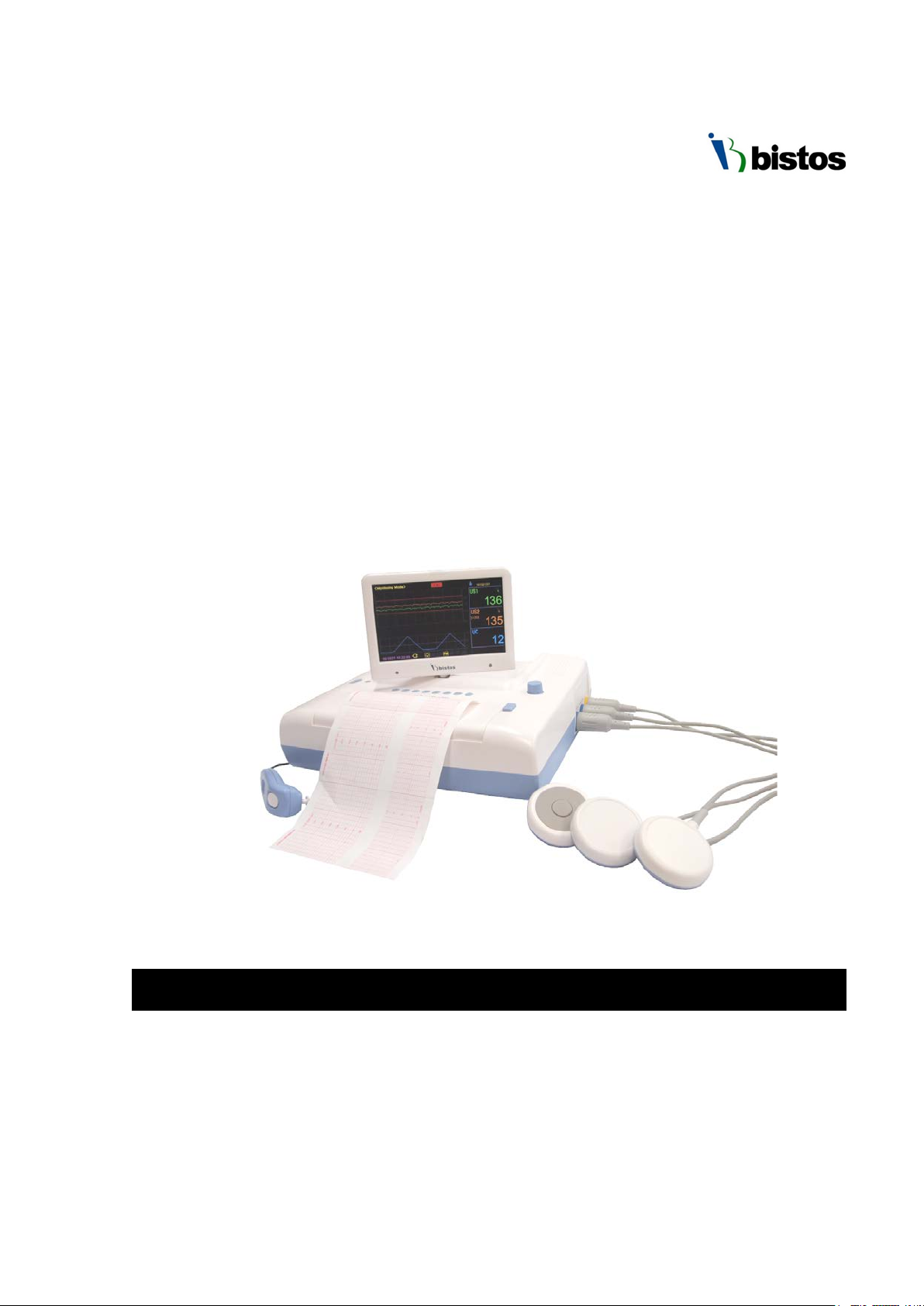
BT-350
Fetal Monitor
Operation Manual
BT-350, BT-350E
Keep this manual for future reference
Printed in Korea, July 2019
Page 2

BT-350 Operation Manual
Contents
0. Safety information ·································································································· 3
0.1 General precautions, warnings, and cautions ········································································· 5
0.2 Shock hazards ···························································································································· 9
0.3 General precautions on environment ····················································································· 10
1. System basics ·········································································································· 11
1.1 Intended use ······························································································································ 11
1.2 Operating principle ···················································································································· 11
1.3 System configurations ·············································································································· 11
1.4 Product outlook ························································································································ 13
1.5 Description of system components ························································································· 14
1.6 Understanding the display ······································································································· 16
1.7 Essential performance ··············································································································· 19
2. Operation of BT-350·································································································· 20
2.1 System startup: self-test ·········································································································· 20
2.2 Buttons ····································································································································· 20
2.3 Control knob and system setting ······························································································· 21
2.4 Printer paper select ·················································································································· 23
2.5 Data saving ······························································································································· 24
2.6 Trend mode ································································································································ 25
2.7 CTG (Cardiotocography) analysis function ················································································ 25
2.8 CCV (Cross-channel verification) function ··············································································· 27
3. Operation of BT-350E ································································································ 29
3.1 Buttons ····································································································································· 29
3.2 Information messages ·············································································································· 29
3.3 Control knob and system setting ····························································································· 30
3.4 Data saving ······························································································································· 35
3.5 CCV (Cross-channel verification) function ··············································································· 36
4. Understanding alarms ····························································································· 37
5. Pinter ····················································································································· 38
5.1 Loading paper ··························································································································· 38
5.2 Printing ···································································································································· 38
6. Monitoring fetal heart rate ····················································································· 40
6.1 Electromagneic interference ···································································································· 40
6.2 Monitoring sequence overview ······························································································· 40
6.3 Detail procedure ······················································································································ 41
7. Uterine contraction (UC) ························································································· 43
7.1 Monitoring sequence overview ······························································································· 43
7.2 Detail procedure ······················································································································ 43
1
Page 3

BT-350 Operation Manual
8. Event marker ·········································································································· 45
8.1 Event marker ···························································································································· 45
8.2 Clinical event marker ··············································································································· 45
9. Cleaning and disinfection ························································································ 46
9.1 Monitor ···································································································································· 46
9.2 Probes ······································································································································ 46
9.3 Belt ··········································································································································· 47
9.4 Contacting components ··········································································································· 47
9.5 Description of Cidex
10. Specifications ·········································································································· 48
11. Troubleshooting and maintenance ·········································································· 51
11.1 Self-test ·································································································································· 51
11.2 Ultrasound transducer test ···································································································· 51
11.3 UC (TOCO) probe test ············································································································· 51
11.4 Battery ···································································································································· 52
11.5 Maintenance ·························································································································· 52
TM
·············································································································· 47
12. Manufacturer’s declaration on EMC ········································································ 53
12.1 Electromagneic emissions ······································································································ 53
12.2 Recommended separation distances between portable and mobile RF communications
equipment and BT-350 ··················································································································· 54
12.3 Electromagnetic immunity ····································································································· 55
Product warranty ·········································································································· 57
2
Page 4
BT-350 Operation Manual
Alerts you to a potential serious outcome, adverse event or safety
injury to the user or patient.
Alerts you to where special care is necessary for the safe and
serious injury.
Used to identify safety information.
During the operation, do not disconnect any cable.
0 Safety information
This manual is for trained healthcare professionals using the BT-350 fetal monitor. It describes
how to set up and use the monitor and transducers. Familiarize yourself with all instructions
including warnings and cautions before starting to monitor patients.
You should be:
Trained in the use of fetal heart rate(FHR) monitors
Trained in the interpretation of FHR traces.
Familiar with using medical devices and with standard fetal monitoring procedures.
In this manual, the following symbols are used for the purpose of:
WARNING
hazard. Failure to observe a warning may result in death or serious
effective use of the product. Failure to observe a caution may
CAUTION
result in minor or moderate personal injury or damage to the
product or other property, and possibly in a remote risk of more
Symbols Used
The following symbols identify all instructions that are important for safety. Failure to follow these
instructions can lead to injury or damage to the fetal monitor. When used in conjunction with the
following words, the symbols indicate:
The following symbols are placed on product, label, packaging and this manual in order to stand for
the information about:
Be well-known this information thoroughly before using BT-350.
Power ON/OFF button
Indicates the need for the user to consult the instructions for use
External Signal IN/OUT port
IPX8
IPX8 Protected against the effects of continuous immersion in water (1 meter
of water for over 40 minutes)
Refer to the operation manual. Read the manual before placing the device.
3
Page 5
BT-350 Operation Manual
his symbol indicates the authorized representative in the European
This symbol indicates compliance with the essential requirements and
This symbol indicates to not dispose of the device together with
In order to comply with EU Directive 2002/96/EC on Waste Electrical and
This product may contain material which
DO NOT
be RECYCLED in accordance with local regulations, contact your local
Indicates the weight limit
This symbol indicates the manufacturer.
This symbol indicates the production date.
This symbol indicates the serial number of the device.
T
Community of the manufacturer.
This symbol indicates a type BF applied part.
This symbol indicates to keep the device dry.
This symbol indicates the correct upright position of a package
This symbol indicates the device is fragile.
This symbol indicates the temperature limitation for operation, transport,
and storage.
This symbol indicates the humidity limitation for operation, transport, and
storage.
This symbol indicates the packing material is recyclable.
provisions of the Medical Device Directive 93/42/EEC as amended by
2007/47/EEC.
unsorted municipal waste(for EU only). The solid bar symbol indicates
that the mains adapter is put on the market after 13 August 2005.
DISPOSAL
Electronic Equipment (WEEE):
could be hazardous to human health and the environment.
DISPOSE of this product as unsorted municipal waste. This product needs to
authorities for more information. This product may be returnable to your
distributor for recycling - contact the distributor for details.
4
Page 6

BT-350 Operation Manual
WARNING
BT-350 is not intended for use during defibrillation, electro-surgery, or
0.1 Before using the monitor
Fetal monitoring technology available today is not always able to differentiate a fetal heart rate (FH)
signal source from a maternal heart rate (MHR) source in all situations. Therefore, you should
confirm fetal life by independent means before starting to use the fetal monitor, for example, by
palpation of fetal movement or auscultation of fetal heart sounds using a fetoscope, stethoscope,
or Pinard stethoscope. If you cannot hear the fetal heart sounds, and you cannot confirm fetal
movement by palpation, confirm fetal life using obstetric ultrasonography. Continue to confirm
that the fetus is the signal source for the FHR during monitoring.
Be aware that a MHR trace can exhibit features that are very similar to those of a FHR trace, even
including acceleration and decelerations. Do not rely solely on trace pattern features to identify a
fetal source.
It is possible to pick up maternal signal sources, such as maternal heart, aorta, or other large
vessels as the FHR. Misidentification may occur when the MHR is higher than normal (especially
when it is over 100 bpm).
Intended use
BT-350 fetal monitor is intended for non-invasive monitoring of fetal heart rates and
uterine activity. BT-350 is intended for generating alarms from fetal heart rate, for
displaying, storing and recording patient data and related waveforms.
BT-350 is intended for use by trained health care professionals.
BT-350 is intended for use in labor and delivery rooms and antepartum testing areas in
the hospital environment.
magnetic resonance imaging (MRI).
Indications for use
BT-350 is indicated for use by health care professionals for monitoring the fetal heart rate.
5
Page 7

BT-350 Operation Manual
0.2 General precautions, warnings and cautions
Before using BT-350, read all section of this manual carefully because there are additional
warnings and cautions which relate to specific features of the monitor.
The warnings and cautions in this section relate to the equipment in general and apply to all
aspects of the monitor. The listed order does not imply any order of importance.
Observe all precautions to ensure the safety of the patient and those near the instrument.
• Examine the monitor and any accessories periodically to ensure that the cables, line cords,
transducers, and instruments do not have visible evidence of damage that may affect patient
safety or monitoring performance. The recommended inspection interval is once per week or
less. Do not use the monitor if there is any visible sign of damage.
• Only the AC line cord supplied with the BT-350, or its equivalent, is approved for use with the
BT-350.
• Do not attempt to service the BT-350 monitor. Only qualified service personnel by Bistos Co.,
Ltd. should perform any needed internal servicing.
• The BT-350 is not specified or intended for operation during the use of defibrillators or during
defibrillator discharge.
• The BT-350 is not specified or intended for operation in the presence of electrosurgical
equipment.
• The BT-350 is not specified or intended for operation in conjunction with any other type of
monitoring equipment except the specific devices that have been identified for use in this
Operator’s Manual.
• Perform periodic safety testing to ensure proper patient safety. This should include leakage
current measurement and insulation testing. The recommended testing interval is once per
year.
• Do not operate the BT-350 monitor if it fails to pass the power on self-test procedure.
6
Page 8

BT-350 Operation Manual
WARNING
Thoroughly read and understand the manual prior to use of BT-350. Failure to do so
Check the rating of the power source compatible with the input voltage rating of the
could result in personal injury or equipment damage.
Only properly trained personnel should use BT-350 as directed by an appropriately
qualified attending physician aware of currently known risks and benefits.
This device has been validated with the accessories and options listed in this manual
and found to comply with all relevant safety and performance requirements
applicable to the device. It is, therefore the responsibility of that person or
organization who makes an unauthorized modification or incorporates an
unapproved attachment to the device.
Use of accessories, transducers and cables other than those specified or provided by
the manufacturer of this equipment could result in increased electromagnetic
emissions or decreased electromagnetic immunity of this equipment and result in
improper operation.
Use only certified accessories with the appropriate International Electrotechnical
Commission (IEC) 60601 harmonized standard.
Medical electrical equipment needs special precautions regarding EMC and needs to
be installed and put into service according to the EMC information provided in this
manual. Portable RF communications equipment (including peripherals such as
antenna cables and external antennas) should be used no closer than 30 cm (12
inches) to any part of the device, including cables specified by the manufacturer.
Otherwise, degradation of the performance of this equipment could result.
Use of this equipment adjacent to or stacked with other equipment should be
avoided because it could result in improper operation. If such use is necessary, this
equipment and the other equipment should be observed to verify that they are
operating normally
Do not use in the presence of flammable anesthetics. Personal injury or equipment
damage could occur.
Do not connect to an electrical outlet controlled by a wall switch.
Use only patient cables and transducers supplied with the monitor. Use of any other
patient cables may result in out-of-specification performance and possible safety
hazards.
An operator may only perform maintenance procedures specifically described in this
manual.
Do not remove the covers of BT-350 yourself to avoid damage to the equipment and
unexpected electric shock. Only qualified Bistos service engineer must repair BT-350
or replace a component.
7
Page 9

BT-350 Operation Manual
adapter.
Only use the supplied or appointed AC/DC adaptor.
CAUTION
The equipment conforms to Class I according to IEC/EN 60601-1(Safety of Electric
When the printer door is open, do not put the finger to the inside of BT-350. This can
Medical Equipment)
This equipment conforms to Level B according to IEC/EN 60601-1-2 (Electromagnetic
Compatibility Requirements)
Keep the operating environment free of dust, vibrations, corrosive, or flammable
materials, and extremes of temperature and humidity. The unit should be kept clean
and free of transducer gel and other substances.
When installing the unit into a cabinet, allow for adequate ventilation, accessibility for
servicing, and room for adequate visualization and operation.
Do not operate the unit if it is damp or wet because of condensation or spills. Avoid
using the equipment immediately after moving it from a cold environment to a warm,
humid location.
Never use sharp or pointed objects to operate the front-panel switches.
General-purpose personal computers and modems are not designed to meet the
electrical safety requirements of medical devices. The RS-232C connector on the BT350 is electrically isolated to permit safe connections to non-medical devices, which
should be connected with a cable of sufficient length to prevent the non-medical
equipment from contacting the patient. If the BT-350 have to be connected with
other medical devices, it must comply with the standards IEC/EN 60601-1 and IEC/EN
60601-1-2.
Do not autoclave or gas sterilize the monitor or any accessories. Follow cleaning and
disinfection instructions in Section 9 of this manual.
Do not immerse BT-350 main body and transducers in liquid. When using solutions,
use sterile wipes to avoid pouring fluids directly on the transducer. Follow cleaning
and disinfection instructions in Section 9 of this manual.
When washing the transducer belts, the water temperature must not exceed 60°C
(140°F).
When loading paper, the paper must be put above the shaft. Otherwise, the paper
can be declined on one side.
If the equipment is used in the area where the integrity of the external protective
conductor in the installation or its arrangement is in doubt, equipment shall be
operated from its internal electrical source when the optional battery is selected.
8
Page 10

BT-350 Operation Manual
CAUTION
cause the finger wound. Also, do not prick the inside of BT-350 when the printer door
is open. This can cause damage to the device or electric shock.
WARNING
Do not attempt to connect or disconnect a power cord with wet hands. Make
case of you have some problems with the power adaptor, we recommend that
Unplug the unit from its power source prior to cleaning or maintenance to
ome chemical cleaning agents may be conductive and leave a residue that
to contact electrical components and do not spray cleaning solutions onto any
d only into a properly
nit to excessive moisture that would allow for liquid
Due to the risk of electrical shock hazard, only qualified personnel with
appropriate service documentation should service the unit.
0.3 Shock hazards
sure that your hands are clean and dry before touching a power cord.
Do not attempt to disassemble the power adaptor with no permission. It may
cause an electric shock. Also, it has a low possibility of reaching to death. In the
you have to contact to us first of all.
During upgrading the BT-350, do not use the BT-350 on the patient. This can
cause an electric shock to the patient.
prevent personal injury or equipment damage.
S
may permit a build-up of conductive dust or dirt. Do not allow cleaning agents
of these surfaces. Personal injury or equipment damage could occur.
To ensure grounding reliability, plug the AC power cor
grounded 3-wire hospital-grade or hospital-use outlet. Do not use extension
cords. If any doubt exists as to the grounding connection, do not operate the
equipment. Personal injury or equipment damage could occur.
Do not expose the u
pooling. Personal injury or equipment damage could occur.
Do not touch the patient and signal input/output parts simultaneously
9
Page 11
BT-350 Operation Manual
0.4 General precautions on environment
Do not keep or operate the equipment under the environment listed below.
Avoid placing in an area
exposed to moisture. Do
not touch the equipment
with a wet hand.
Avoid placing in an area
where there is a high
variation of temperature.
Operating temperature
ranges from 10°C ~ 40°C.
Operating humidity ranges
from 5% ~ 85%.
Avoid exposure to direct
sunlight
Avoid in the vicinity of
electric heater
Avoid placing in an area
where there is an
excessive humidity rise or
ventilation problem.
Avoid placing in an area
where chemicals are
stored or where there is in
danger of gas leakage.
Do not disjoint or
disassemble the device.
Bistos Co., Ltd. does not
take responsibility for it.
Avoid placing in an area
where there is an excessive
shock or vibration.
Avoid dust and especially
metal material enter into
the equipment.
Power off when the
equipment is not fully
ready to operate.
Otherwise, the equipment
could be damaged.
10
Page 12

BT-350 Operation Manual
1 System basics
1.1 Intended use
BT-350, the non-invasive fetal monitoring system provides graphical and numerical information on fetal
heart rate (FHR) and maternal uterine activity (UA) to help assess fetal well-being before and during
labor. FHR often exhibits decelerations and accelerations in response to uterine contractions or fetal
movements; certain patterns are indicative of hypoxia. Examination of these patterns, the baseline
levels, and variability characteristics can indicate the need to alter the course of labor with drugs or
perform an operative delivery.
It is intended to be used to a pregnant woman only by trained and qualified personnel such as medical
professionals especially physicians and nurse of obstetrics in the medical institution having antepartum
examination rooms, labor, and delivery rooms.
1) Intended patient population
- Pregnant women
2) Intended user profile
- Nursing staff or physicians who is qualified
- Basic experiences or knowledge on the medical field, especially on obstetrics
- Trained or requested to read IFU before use
3) Environment of use
1. Hospital (birthing center, delivery rooms)
2. Requirements: Stable power source
1.2 Operating principle
The device detects the fetal heart rate and heartbeat sound using the Doppler effect of ultrasound and
measure the relative uterine contraction using the strain gauge and output the result to the printer.
The two probes are equipped to detect the fetal heart rate and heartbeat sound of twins.
The detection and measurement result can be displayed on the LCD (BT-350) or on LED (BT-350E).
1.3 System configurations
The basic configuration of BT-350
• Main body
• Two Doppler probes
11
Page 13
BT-350 Operation Manual
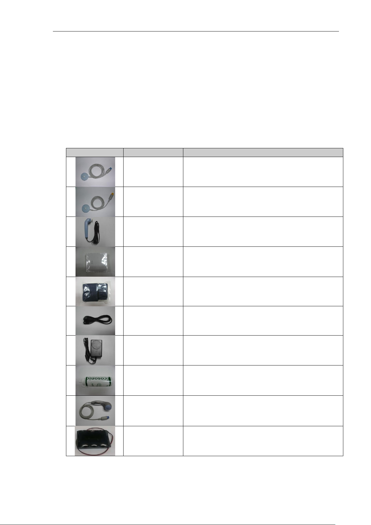
Accessory
Name
Description
• UC probe
Options of BT-350
• AST probe
• Li-ion Battery (14.8V, 2600mAh)
Doppler Probe
UC Probe
Ultrasound Transducer for Measuring FHR
(IPX8: Waterproof)
Pressure Sensor for Measuring Uterine contraction(UC)
(IPX8: Waterproof)
Event Marker Used for a Fetal Movement event
Z-folded type
Paper
Z-folder type thermal Paper
Probe Belt Used for Holding Doppler Probe and/or UC Probe
Power Cord AC Power cord
Power Adaptor
Adaptor for transform AC Power
(100-240V ~) to DC 18V(2.8A)
Ultrasound Gel
AST Probe
(Option)
Ultrasound transmission gel
(Sanipia, ECOSONIC)
Acoustic Stimulation
Test P r obe
LI-ION Battery 14.8V, 2600mAh
12
Page 14
BT-350 Operation Manual
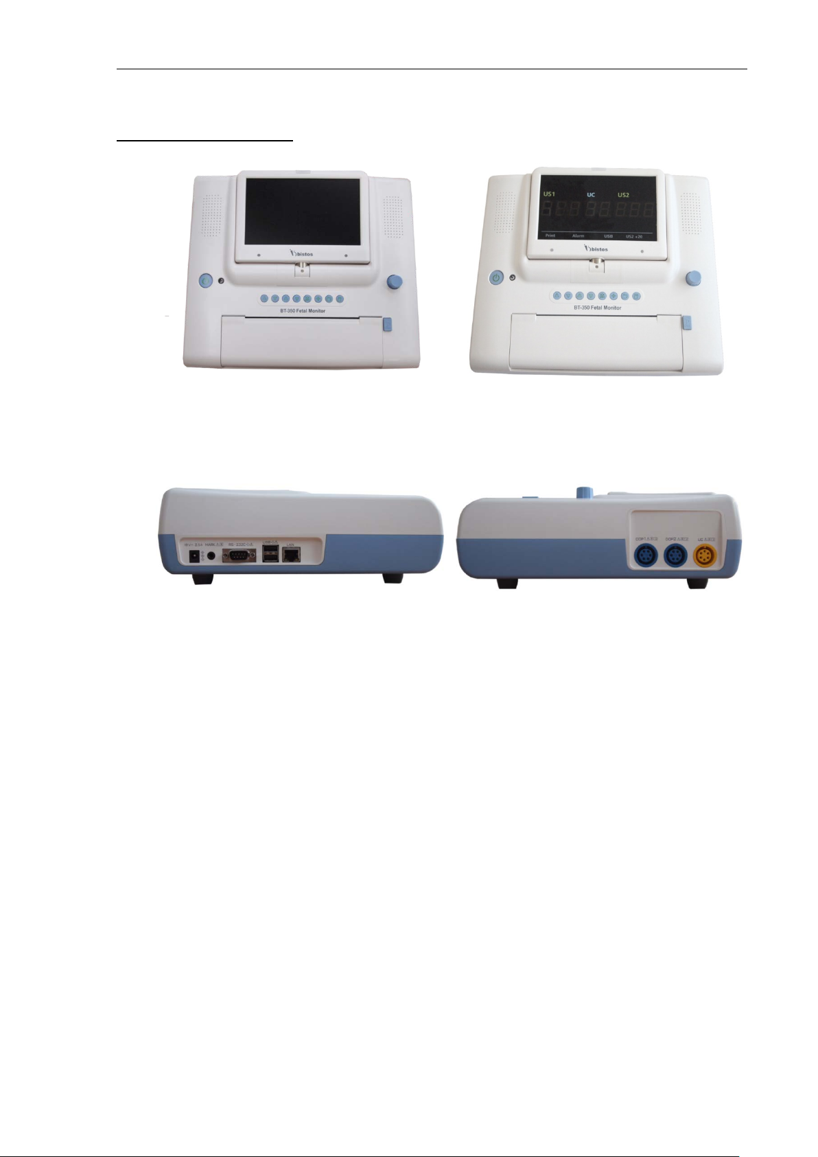
1.4 Product outlook
BT-350 BT-350E
Figure1-1: Front view
Left side view Right side view
Figure1-2: Side view
13
Page 15
BT-350 Operation Manual
1.5 Description of System components
14
Page 16
BT-350 Operation Manual
Speaker
Power indicating LED (AC: Green / Battery: Orange)
Control knob
DOP1 volume UP/DOWN button: Increase or decrease DOP1 fetal audio
volume in monitoring mode
DOP2 volume UP/DOWN button: Increase or decrease DOP2 fetal audio
Alarm sound ON/OFF button: Makes the alarm sound enable or disable
⑫
Print door open button
⑬
Printer door
7 segment LED Display(for BT-350E)
Event marker connector
③
RS-232C port
④
USB port
⑤
LAN port
No
①
②
③
④
⑤
⑥
⑦
⑧
⑨
⑩
⑪
⑭
Name & Description
TFT Color LCD
Power ON/OFF button: Turns the power On or Off
volume in monitoring mode
in monitoring mode
UC reference button: Resets the UC baseline in monitoring mode
Mode change button: The monitor operating mode change
Printer ON/OFF button: Turn the printer On or Off
①
②
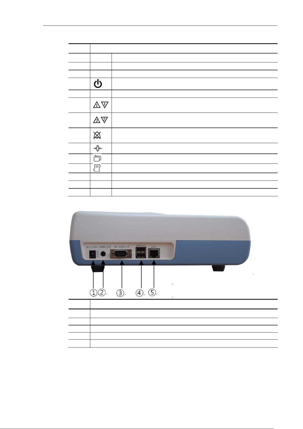
Name & Description
Power adaptor jack connector
15
Page 17
BT-350 Operation Manual
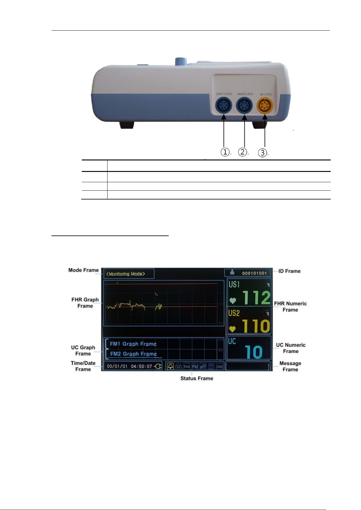
②
DOP2/AST connector
③
UC connector
Name & Description
①
DOP1/AST connector
1.6 Understanding the display
1.6.1 BT-350 main monitoring screen display
1.6.1.1 Mode frame
The mode frame shows the current mode. There are monitoring mode, setup mode, and trend mode.
1.6.1.2 Patient ID frame
This frame displays patient identification. The monitor encodes the identification using the date to
ensure no duplication of IDs. The user may enter a patient name if desired.
Figure 1-3 – Main monitoring screen display (BT-350) – Graph mode
16
Page 18

BT-350 Operation Manual
1.6.1.3 FHR graph frame
The FHR graph frame displays a graphical representation of the FHR. The horizontal line is scaled
according to the printer paper setting (Refer to the “Printer paper select” chapter). The graph displays
4 minutes and 30 seconds of data.
This frame will show two heart rate trends when two ultrasound transducers are connected.
1.6.1.4 FHR numeric frame
The FHR numeric frame displays the fetal heart rate, a heart icon, and the volume icon. The heart rate
value displays the most recently calculated fetal heart rate. When a valid heart rate is detected, the
heart icon blinks at the measured heart rate interval. The volume icon indicates the current speaker
volume setting.
When the second ultrasound transducer is connected, the heart rate frame “US2” will display the fetal
heart rate, a heart rate icon, and the volume icon automatically. The trace-offset (DOP2 offset) icon
[+20] will also appear in the FHR frame if two ultrasound transducers are connected and ultrasound
trace offset (DOP2 offset) has been enabled.
1.6.1.5 UC (TOCO) graph frame
This frame displays the relative uterine contraction in graph form. The scale is from zero to 100 in
relative units. The graph displays 4 minutes and 30 seconds of data.
1.6.1.6 UC (TOCO) numeric frame
This frame displays the numerical value from the UC probe representing relative uterine contraction.
This frame also shows the present UC baseline value. A user can reset the baseline to 10.
1.6.1.7 Time/Date frame
This frame shows the current time and date and power source. The time and date can be changed. If
the device is operating using AC power then AC power icon is displayed. If the device is operating by
battery power, then a battery icon is displayed. The battery icon also displays charging status. If the
battery option is equipped selected, the internal battery is used when AC power disconnected.
The battery icon will flash when the battery is low (less than 10 minutes of remaining operating time).
If the battery is low (Low Battery) the printer will stop operating and the battery icon will turn to red.
The AC power should be connected to the device to charge the battery. The device will operate
normally while the AC power is charging the battery. The battery charging time is approximately 14
hours.
1.6.1.8 Status frame
This frame displays alarm status icon, printer status icon, printer speed set value, fetal movement set
status, auto printing status, save icon, and USB icon. The alarm icon is a bell. A diagonal line on the bell
indicates that alarm is disabled.
1.6.1.9 Message frame
This frame displays the error and current operation status. The error message will be displayed when
17
Page 19

BT-350 Operation Manual
Message
Description
Symbol
Name
Description
Indicating the speaker volume setting for the fetal echo
sounds
Indicates the battery charge status (Only when the BT-
350 is operated by battery, this icon is displayed.)
the device is unable to operate properly. If this error message displayed, stop using the device and
check.
DOP1 OPEN DOP1 is not connected while BT-350 is monitoring
DOP2 OPEN DOP2 is not connected while BT-350 is monitoring
DOOR OPEN Printer door is opened while BT-350 is printing
No PAPER Paper is not loaded while BT-350 is printing
LOW BAT Battery’s charging level is low while BT-350 is monitoring
Figure 1-4 – Main monitoring screen display (BT-350) – Number mode
Heart Rhythm Icon Blinking according to heart rate
Alarm Sound Icon Indicating of Alarm sound enable/disable
Volume Icon
Mute Icon In the case of volume level 0
Print Icon Indicating a printing status
Save Icon Indicating a data saving status
Print Speed Icon Indicating print speed status
Auto Print Icon Indicating of the status of the auto printing function
AC Power Icon Indicates the unit is operating on AC power
Battery Status Icon
USB Icon Indicating USB connection status.
18
Page 20

BT-350 Operation Manual
Display
Description
Alarm
Indicating of Alarm sound enable/disable
USB
Indicating of USB record status
US +20
Indicating of US2 offset enable/disable
1.6.2 BT-350E main monitoring screen display
Figure 1-5 – Main monitoring screen (BT-350E)
1.6.2.1 Heart Rhythm
The heart symbol is turned on according to FHR value. If FHR value is out of normal range (30 ~ 240),
the heart symbol is turned off.
1.6.2.2 FHR/UC frame
The FHR frame displays the detected fetal heart rate. When the second ultrasound transducer is
connected, the “US2” frame will display the fetal heart rate too.
This frame displays the numerical value from the UC probe representing relative uterine contraction.
This frame also shows the present UC baseline value. A user can reset the baseline to 10.
1.6.2.3 Status frame
This frame shows the BT-350 LED status.
Print Indicating a printing status
1.7 Essential performance
1) Accuracy of fetal heart rate
The accuracy for the FHR should be within +/- 2% at the range 30 to 240 BPM.
2) The display range of UC
The display range of the UC is from 0 to 100.
19
Page 21

BT-350 Operation Manual
CAUTION
Never use sharp or pointed objects to operate the front-panel switches.
Symbol
Name
Description
Decreases or increases Dop1 fetal audio volume in
Decreases or increases Dop2 fetal audio volume in
Makes the alarm sound enable or disable in monitoring
2 Operation of BT-350
2.1 System startup: Self-test
The monitor performs a self-test each time it is turned on. This process allows the monitor to check
various systems for proper operation. The monitor displays the startup screen during the power-onself-test. When the test is successfully completed the BT-350 displays the monitoring screen.
If a malfunction is detected an error message displays and an error tone is sounded. The error tone will
continue until the power is turned off. If this occurs, remove the monitor from use until appropriate
action is taken.
Fig. 2.1 Self-test display
2.2 Buttons
There are seven buttons located on the front panel. The buttons are activated by pushing with the
finger until an audible click sound is heard.
The operation of the button is as below.
Power On/Off Button Turns the power on or off.
Dop1 Volume
Up/Down Button
Dop2 Volume
Up/Down Button
monitoring mode.
monitoring mode.
Alarm On/Off Button
mode.
20
Page 22

BT-350 Operation Manual
Puts the monitor into trend scroll mode. The trend
frames show historical patient data and the control
knob provides navigation capability.
Parameter
Factory Default
Dop2 Trace Separation (Dop2 Offset)
0 BPM
FM Graph
OFF
Printing Speed
3 cm/min
Auto Printing
0 MIN
Patient Name
blank
Patient ID
Date/Sequential number
Date
YY/MM/DD
Time
HH:MM:SS
Auto Save
OFF
Language
English
Paper
FS151-90-80R-01
UC Reference Button Resets the UC baseline in monitoring mode.
Mode Button
Record On/Off Button Turns the record on or off.
2.3 Control knob and system setting
Use the control knob to select the parameter to change and to adjust the parameter value selected.
Press down the knob activates the setup menu as shown in Fig.2.2. Turn the knob clockwise or
counterclockwise to move the cursor and press down it to select the parameter. Turn the knob to
change the value and press down to store the value. The basic operation sequence is summarized in
the below table. Select “ESC” and press down the knob to save the exit setup menu.
Fig. 2.2 System setup menu
The monitor has several configuration settings that the user can change. These parameters are
unaffected when the monitor is powered down. Below is the default setting value of parameters.
Fetal Heart Rate Upper Alarm Limit 190 BPM
Fetal Heart Rate Lower Alarm Limit 110 BPM
21
Page 23

BT-350 Operation Manual
Activity
Desired Result
Press down
Enter the setup menu
Rotate
Move the cursor
Press down
Select the parameter to change.
Rotate
Change the value
Press down
Store the new value.
The basic operation of the control knob to parameter settings is as follows.
2.3.1 Alarm upper limit/lower limit set
The upper and lower alarm limit can be changed. The adjustable range for upper limit is [Lower limit
+10] ~ 240 BPM with 5 BPM step. The adjustable range for a lower limit is 30 ~ [Upper limit – 10] BPM
with 5 BPM step.
2.3.2 DOP2 offset set
The two waveforms for each Doppler transducer can be separated to prevent some confusing and
enable to see the waveform clearly. When ultrasound trace separation is enabled, the trend data for
ultrasound channel 2 is shifted up by 20 BPM in printing. This feature is useful when both heart rates
waveforms are similar. The heart rate value shown in the numeric frame is not affected. If DOP2 offset
is selected, [+20] is displayed in US2 numeric frame.
2.3.3 Fetal movement (FM) graph
The fetal movement graph display can be turned on and off.
2.3.4 Printing speed
The printing speed can be selected among 1cm/min, 2cm/min, and 3cm/min.
2.3.5 Auto printing
The printer can be turned off automatically. If the value is set to 0, the printer will print out until the
paper ended. If the value is set to 10, the printer will turn off after 10 minutes. You can choose among
0, 10, 20, 30, 40, 50, and 60.
2.3.6 Entering the patient name
You can enter a patient name if required. If you select the [NAME] item, you can see the following
display to enter the name. If you want to enter the second character of the selected character set, you
can press down the knob twice. For example, D requires one press down and F requires three press
down.
.QZ ABC DEF GHI JKL MNO
PRS TUV WXY
ESC
22
Page 24

BT-350 Operation Manual
M1911A
50-210 bpm
50-210 bpm
2.3.7 Entering the patient ID
Patient ID is generated automatically when BT-350 has turned on. This ID is composed of YYMMDD + 3
digits serial number. The 3 digits number can be changed manually.
2.3.8 Set date and time
Set the date and time if required. Enter date in the YY/MM/DD format and time in the 24 hours format.
2.3.9 Set auto save
You can save the measured data manually or automatically. If [AUTO SAVE] function activates, all the
measured data is stored from the power on. The default value for this function is OFF.
2.3.10 Set language
The default language setting is English. You can choose among English, Chinese, Spanish, German,
French, Indonesian, Russian, Portuguese, Turkish, Polish, Italian, Korean, Japanese, and Serbian.
2.3.11 CMS (Central monitoring system) settings
You can change the communication channel, IP address, subnet address, gateway address, port address,
and HRV (Heart Rhythm Variability) sensitivity. You can choose the communication channel between
Serial and Ethernet. And you can choose the HRV sensitivity among low, middle, and high. You can
enter a value for other parameters.
2.4 Printer paper select
You can use two different types of paper, FS151-90-80R-01 and M1911A, with BT-350. If you press
down the control knob during the self-test, you can select the printer paper.
Fig. 2.3 Printer paper select
Paper Graph Display Area Print Area
FS151-90-80R-01 30-240 bpm 30-240 bpm
23
Page 25

BT-350 Operation Manual
CAUTION
If you use a different type of paper from the selected paper type, the printed data will be
changed to 110.
incorrect. Be sure to check the selected paper type is the same with used paper.
When paper type is changed, the alarm upper limit is changed to 190 and alarm lower limit is
2.5 Data saving
The measured data can be saved to the monitor itself and USB, if connected, at the same time. For
each patient, up to 3 hours of data can be saved. Totally 450 hours of data can be saved. The saved
data can be totally copied moved from BT-350 to USB memory later.
2.5.1 How to save data
Press down the mode button [ ] to activate the following menu.
Fig. 2.4 Save Date display
Select [Save Date] item and press down the control knob to start the saving function. If the save
function activated save icon [ ] is activated by yellow color and rotate. Press down the mode button
[ ] to finish data saving. If the USB memory is connected, the USB icon activated by yellow color and
data saved to USB memory simultaneously.
2.5.2 How to copy the saved data to USB
Press down the mode button [ ] to activate menu while USB memory has connected. Select “Trend
Mode”. Turn the control knob to select USB and the USB will turn to red color. Then press down the
control knob to copy the saved data to USB memory.
24
Page 26

BT-350 Operation Manual
Button
Function
Searching for saved data by patient ID. Selecting Previous /
Next Patient
Searching for saved data by saved page. Selecting Previous /
Next Page
Fig. 2.5 Trend mode display
2.6 Trend mode
In trend mode, you can see the saved data. Press down the mode button [ ] to activate the menu
shown in figure 2.4. Rotate the control knob to select the “Trend Mode”. Press down the control knob
to enter the trend mode.
The data saved date and time and the relevant patient ID are displayed. You can search for data by a
patient or by page and tracing saved graphic data.
Tracing the saved graphic data
2.7 CTG (Cardiotocography) analysis function
The CTG analysis function is a computerized diagnosis of fetal heart rate and uterine contraction
patterns.
When this function is activated, a CTG algorithm monitors continuous FHR and UC value for 20 minutes
and analyzes FHR variability and relative FHR response to UC change.
To activate this function, press down the control knob during self-test for 4 times and then the
following menu will be displayed.
25
Page 27

BT-350 Operation Manual
Fig. 2.6 CTG analysis function
After selecting ON the CTG analysis function, you can use this function by pressing the [Print] button in
the monitoring mode. On pressing the [Print] button, the mode will change from <Monitoring Mode>
to <CTG Mode> and the printing will be started. On the FHR frame, the <Baseline Value> will be
displayed.
Fig. 2.7 CTG mode
When you press down the [Print] button again after more than 20 minutes elapsed, printing will be
stopped and CTG analysis will be ended. The analysis result will be displayed and printed.
Fig. 2.8 CTG results in monitoring mode
26
Page 28

BT-350 Operation Manual
Fig. 2.9 CTG result in trend mode
2.8 CCV (Cross-channel verification) function
When monitoring two fetuses with two Doppler probes, CCV function will compare the values from
both probes and alerts when the values could be the same source (fetus).
If the difference between two probe values is within 2 bpm for more than 25 seconds during 30
seconds monitoring period, CCV alert will be generated and icon will be displayed.
To activate this function, press down the control knob during self-test for 3 times and then the
following menu will be displayed.
Fig. 2.10 CCV function
Fig. 2.11 CCV displayed
If the CCV appears during printing the data, icon will be printed on the paper.
27
Page 29

BT-350 Operation Manual
Fig. 2.12 CCV printed
28
Page 30

BT-350 Operation Manual
CAUTION
Never use sharp or pointed objects to operate the front-panel switches.
Symbol
Name
Description
Decreases or increases Dop1 fetal audio volume in
Decreases or increases Dop2 fetal audio volume in
Puts the monitor into trend scroll mode. The trend
provides navigation capability.
Message
Description
3 Operation of BT-350E
3.1 Buttons
There are seven buttons located on the front panel. The buttons are activated by pushing with the
finger until an audible click sound is heard.
The operation of the button is as below.
Power On/Off Button Turns the power on or off.
Dop1 Volume
Up/Down Button
Dop2 Volume
Up/Down Button
Alarm On/Off Button
UC Reference Button Resets the UC baseline in monitoring mode.
Mode Button
Record On/Off Button Turns the record on or off.
monitoring mode.
monitoring mode.
Makes the alarm sound enable or disable in monitoring
mode.
frames show historical patient data and the control knob
3.2 Information messages
The following messages are displayed to indicate the error and current operation status. The error
message is displayed when the monitor is unable to operate properly. If the error message is showing
up, stop using BT-350E and take appropriate action.
DOP1 OPEN. Doppler probe is not
connected to DOP1 connector
DOP2 OPEN. Doppler probe is not
connected to DOP2 connector.
29
Page 31

BT-350 Operation Manual
Message
Description
Parameter
Factory Default
Fetal Heart Rate Upper Alarm Limit
190 BPM
Fetal Heart Rate Lower Alarm Limit
110 BPM
Dop2 Trace Separation (Dop2 Offset)
0 BPM
FM Graph
OFF
Printing Speed
3 cm/min
Auto Printing
0 MIN
Paper
FS151-90-80R-01
Activity
Desired Result
Press down
Enter the setup menu
Rotate
Move the cursor
Press down
Select the parameter to change.
Rotate
Change the value
Press down
Store the new value.
DOOR OPEN. The print door is opened.
NO PAPER. Paper is not loaded
LOW BATTERY. Battery charging level is
low
3.3 Control knob and system setting
Use the control knob to select the parameter to change and to adjust the parameter value selected.
The monitor has several configuration settings that the user can change. These parameters are
unaffected when the monitor is powered down. Below is the default set of parameters.
The basic operation of the control knob to parameter settings is as follows.
3.3.1 Alarm upper limit/lower limit set
The upper and lower alarm limit can be changed. The adjustable range for upper limit is [Lower limit
+10] ~ 240 BPM with 5 BPM step. The adjustable range for a lower limit is 30 ~ [Upper limit – 10] BPM
with 5 BPM step.
30
Page 32

BT-350 Operation Manual
Fig. 3.1 Alarm Upper /Lower Limit
3.3.2 DOP2 offset set
The two waveforms for each Doppler transducer can be separated to prevent some confusing and
enable to see the waveform clearly. When ultrasound trace separation is enabled, the trend data for
ultrasound channel 2 is shifted up by 20 BPM in printing. This feature is useful when both heart rates
waveforms are similar. The heart rate value shown in the numeric frame is not affected. If DOP2 offset
is selected, [+20] is displayed in US2 numeric frame.
Fig. 3.2 DOP2 offset
3.3.3 Set date and time
Set the date and time if required. Enter date in the YY/MM/DD format and time in the 24 hours format.
Fig. 3.3 Date and time
3.3.4 Printing speed
The printing speed can be selected among 1cm/min, 2cm/min, and 3cm/min.
31
Page 33

BT-350 Operation Manual
Paper
Graph Display Area
Print Area
M1911A
50-210 bpm
50-210 bpm
Fig. 3.4 Printing speed
3.3.5 Auto printing
The printer can be turned off automatically. If the value is set to 0, the printer will print out until the
paper ended. If the value is set to 10, the printer will turn off after 10 minutes. You can choose among
off, 10, 20, 30, 40, 50, and 60.
Fig. 3.5 auto printing
3.3.6 Fetal movement (FM) graph
The fetal movement graph display can be turned on and off.
Fig. 3.6 Auto printing
3.3.7 Printer paper select
You can use two different types of paper, FS151-90-80R-01 and M1911A, with BT-350. If you press
down the control knob during the self-test, you can select the printer paper.
FS151-90-80R-01 30-240 bpm 30-240 bpm
32
Page 34

BT-350 Operation Manual
CAUTION
If you use a different type of paper from the selected paper type, the printed data will be
changed to 110.
Fig. 3.7 Printer paper select
incorrect. Be sure to check the selected paper type is the same with used paper.
When paper type is changed, the alarm upper limit is changed to 190 and alarm lower limit is
3.3.8 CCV On/Off
When monitoring two fetuses with two Doppler probes, CCV function will compare the values from
both probes and alerts when the values could be the same source (fetus).
If the difference between two probe values is within 2 bpm for more than 25 seconds during 30
seconds monitoring period, CCV alert will be generated and icon will be displayed.
This CCV function can be on and off.
Fig. 3.8 CCV function select
3.3.9 CMS (Central monitoring system) communication channel
CMS communication channel can be selected between serial and Ethernet.
Fig. 3.9 CMS communication channel
33
Page 35

BT-350 Operation Manual
3.3.10 IP address set
Set the IP address as required.
Fig. 3.10 IP address set
3.3.11 Subnet mask set
Set the subnet mask as required.
3.3.12 Gateway set
Set the gateway as required.
Fig. 3.11 Subnet mask set
Fig. 3.12 Gateway set
34
Page 36

BT-350 Operation Manual
3.3.13 Port number set
Set the port number as required.
Fig. 3.13 Port number set
3.3.14 HRV (Heart Rate Variability) sensitivity set
Set the HRV sensitivity as required.
Fig. 3.14 HRV sensitivity set
3.4 Data saving
The measured data can be saved to the USB memory.
After connecting USB memory to BT-350E, press down the mode button [ ] to activate the data
saving function. The USB data saving indicator will be lit and the “ding-dong” sound will be generated.
Fig. 3.15 USB data saving function activated
Press down the mode button [ ] to finish data saving. The USB data saving indicator will be turned
off and the “ding-dong” sound will be generated.
35
Page 37

BT-350 Operation Manual
3.5 CCV (Cross-channel verification) function
When monitoring two fetuses with two Doppler probes, CCV function will compare the values from
both probes and alerts when the values could be the same source (fetus).
If the difference between two probe values is within 2 bpm for more than 25 seconds during 30
seconds monitoring period, CCV information sound will be generated
When the difference between two probe values is more than 2 bpm for more than 5 seconds, the CCV
information sound will be turned off and BT-350E will be operating normally.
If the CCV appears during printing the data, icon will be printed on the paper.
Fig. 3.16 CCV printed
36
Page 38

BT-350 Operation Manual
Repetition
Interval
1. Power on
oor is opened
6. Complete auto printing
4 Understanding alarms
The monitor will generate an alarm when the FHR exceeds the set alarm limits. But these limits have
no significant meaning in clinical uses.
One time exceeding the limits will not generate the alarm. If the alarm condition (exceeding the limits)
endures for more than 20 seconds the alarm sound will be generated and the red led is flashing with
the heart rate value on display will be blinking as long as the alarm condition persists or alarm is
disabled by the user. Pressing the alarm button on the monitor’s keypad can silence the alarm tone.
Alarms are enabled or disabled by pressing the alarm button on the keypad.
Classification Frequency/Sound
Upper
alarm
sound
Alarm
Sound
Lower
alarm
sound
Information
sound
3 seconds
3 seconds
2 seconds
Situation
When FHR exceeds Upper
Limit value over 20
seconds
When FHR goes down
Lower Limit over 20
seconds
2. DOP1 or DOP 2 is
disconnected while BT350 is monitoring.
3. Paper is out while BT-
350 is printing.
4. Printer d
while BT-350 is printing.
5. Battery’s charge level is
low while BT-350 LED is
monitoring.
37
Page 39

BT-350 Operation Manual
5 Printer
5.1 Loading paper
Open the printer door by pressing down the [Printer door open button]. Unwrap a pack of paper and
put it into the paper tray.
A page from the top of the paper pack should drape forward over the shaft of the printer. The
orientation of the paper is with the printed grid facing up (unfolding from the top of the pack) and the
UC grid area is the right side.
Fig. 5.1 Loading paper
5.2 Printing
Print On/Off button — Press the print button [ ] to start printing. Press again to stop printing.
Paper Advance — Press and hold the print button [ ] to fast-forward the paper.
38
Page 40

BT-350 Operation Manual
Press Event marker
woman)
(by a doctor)
FM1 Trace
automatic)
FM2
automatic)
FHR Tra c e
Situation
FM Tr a c e
UC Trace
Symbol Description Source of mark Possible events
Event Mark
Clinical Event Mark
FM1 Detection Mark
FM2 Detection Mark
AST Mark
Fig. 5.2 Printing result
(by a pregnant
Press [ ] button
over 2 seconds
(by algorithm and
(by algorithm and
AST
(by a doctor)
When doctor judges fetus movement
When a pregnant woman feels fetus
movement
happens
When the system detects fetus
movement(FM1)
When the system detects fetus
movement(FM2)
When the system detects AST signal
39
Page 41

BT-350 Operation Manual
CAUTION
The cable of the Doppler probe is not intended to contact the patient. To prevent such contact,
with clean gauze or fabric.
6 Monitoring fetal heart rate
6.1 Electromagnetic interference
Strong electromagnetic fields can interfere with the ultrasound transducer and cause a false heart rate
reading that does not originate from the fetus. This interference is rare and usually found in the vicinity
of large machinery. In order to avoid the possibility of these interferences, the following procedure
should be followed whenever the monitor is to be used in a new location, or if it is known that
electrical machinery is being operated in the vicinity.
After connecting the ultrasound transducer(s), turn on the monitor and observe the heart rate
indications on the screen for 30 seconds. Intermittent display of random heart rate is acceptable.
However, if there is a constant display of a physiological heart rate lasting more than 5 seconds, this is
an indication that there is a source of electromagnetic interference in the vicinity. The following steps
should be taken to determine if it is possible to use the monitor in this environment.
Move all line cords and line-powered equipment at least 200 cm away from the monitor. Check for
extension cords running behind or under the bed and equipment in adjacent rooms. If the artifact
heart rate indication ceased, the monitor may be used normally.
Remove all the line cord from the monitor’s power supply. If the artifact heart rate indication
ceased, the monitor may be used normally.
If these measures do not result in cessation of the heart rate artifact, the monitor can’t be safely used
in this environment.
Fetal heart rate is measured by placing the ultrasound transducer on the maternal abdomen and by
processing the received Doppler echo signal to produce a heart rate and an audio representation of the
echo signal.
please cover the patient’s abdomen section which has a possibility of contacting by the cable
6.2 Monitoring sequence overview
Step 1: Preparing the monitor
Turn the monitor on and verify that the normal monitoring screen appears on the display. Stop
using the monitor if an error occurs.
Check whether the monitor is powered from the internal battery or AC power. If the monitor is
powered from the internal battery, check the power status from on the display to determine
whether the battery has sufficient charge to complete the monitoring session. Use the AC power if
the battery is too low.
40
Page 42

BT-350 Operation Manual
Check the ultrasound transducer to verify proper attachment to the monitor. For monitoring twins,
make sure the second ultrasound transducer is properly connected.
Adjust channel one speaker volume to the middle level. Adjust channel two speaker volume to
zero if monitoring twins.
Apply ultrasound gel to the face of the transducer.
Step 2: Acquiring the fetal heart signal
Determine the location of the fetal heart using palpation or a fetoscope. Place the transducer on
the maternal abdomen and listen to the fetal heart signal. Reposition the transducer for the
loudest fetal heart sound.
Secure the ultrasound transducer with the elastic belt. Make sure that the transducer is still
positioned for the loudest fetal heart signal.
Verify the monitor is displaying fetal heart rate values and that the heart shape icon on the screen
is blinking at the measured heart rate.
Step 3: Acquiring twin’s heart rate
Follow step 2 above to acquire the heart rate for the first fetus.
Decrease the channel one speaker volume and increase the channel two speaker volume to hear
the second heart sound.
Determine the location of the second fetal signal using palpation or fetoscope.
Apply gel to the second ultrasound transducer and place it on the maternal abdomen where the
second fetal signal was located. Reposition the transducer for the loudest fetal heart sound.
Secure the ultrasound transducer with the elastic belt. Make sure that the transducer is still
positioned for the loudest fetal heart signal.
Verify the monitor is displaying fetal heart rate values and that the heart shape icon on the screen
is blinking at the measured heart rate.
Step 4: Monitor adjustment
Readjust the volume settings for the desired loudness.
6.3 Detail procedure
Explain the procedure to the patient.
Place a probe belt under the patient
Turn the monitor on.
41
Page 43

BT-350 Operation Manual
CAUTION
The probe belt may cause allergy or skin side effects to the patient if it is used so long time.
Doppler Probe
Connect the ultrasound probe to the “DOP” connector.
Apply a small amount of ultrasound coupling gel to the face of the transducer.
Determine the position of the fetus using Leopold’s maneuvers. The strongest fetal heart tones are
heard through the fetal back.
Place the transducer face down on the maternal abdomen over the area determined as the fetal
back.
Secure the transducer comfortable in the place by inserting the transducer button through the
button holes on each end of the belt.
Adjust the volume as required.
Press the print button [ ] to activate the printer.
Fig. 6.1 The position of the Doppler probe
42
Page 44

BT-350 Operation Manual
CAUTION
The cable of the UC probe is not intended to contact the patient. To prevent such contact,
with clean gauze or fabric.
7 Uterine contraction (UC)
Uterine contraction is measured externally by placing a pressure sensor (UC sensor) on the maternal
abdomen and measure the relative pressure change.
please cover the patient’s abdomen section which has a possibility of contacting by the cable
7.1 Monitoring sequence overview
Step 1: Preparing the monitor
Turn the monitor on and verify that the normal monitoring screen appears on the display. Stop
using the monitor if an error occurs.
Check whether the monitor is powered from the internal battery or AC power. If the monitor is
powered from the internal battery, check the power status from on the display to determine
whether the battery has sufficient charge to complete the monitoring session. Use the AC power if
the battery is too low.
Check the UC probe to verify proper attachment to the monitor.
Press the UC reference button to adjust the values to the baseline.
Step 2: Acquiring the uterine contraction data
Place the face (button side) of the UC probe on the fundus on the uterus when contractions are
not occurring. No gel is required.
Secure the UC probe with the elastic belt. The uterine contraction reading at this point should be
greater than 30 and less than 90 units. If the readings fall outside of this range, the belt may be
too tight or too loose. If the belt is overtightened, the contraction peaks may have a flat-top at less
than on the UC scale. If the belt is under tightened, the sensor can move and cause unstable
readings. Readjust the belt pressure as needed.
7.2 Detail procedure
Explain the procedure to the patient.
Place a probe belt under the patient
Turn the monitor on.
Connect the UC probe to the “UC” connector.
43
Page 45

BT-350 Operation Manual
Note: After connecting or re-connecting the UC probe to the UC connector, you must wait at least
10 seconds before pressing the UC reference button [ ].
CAUTION
The probe belt may cause allergy or skin side effects to the patient if it is used so long time.
Press the UC reference button [ ] to set the UC baseline at 10.
Position the UC probe on the maternal abdomen over the uterine fundus or where there is the
least maternal tissue and the contractions are strongly palpated.
Secure the UC probe comfortable in the place by inserting the transducer button through the
button holes on each end of the belt.
Between contractions, press the UC reference button [ ] again. This sets UC baseline to 10.
Press the print button [ ] to activate the printer.
Fig. 7.1 The position of UC probe
44
Page 46

BT-350 Operation Manual
8 Event marker
8.1 Event marker
The event marker arrow is provided so that the patient can record the time of important events. The
patient merely presses the marker button at the time an event occurs. This marker time is recorded in
the monitor.
The patient marker icon is an upward pointing arrow [ ]. The monitor will display this arrow in the
information frame of the display. A strip chart printout of the patient record will also show this marker.
8.2 Clinical event marker
When an important event, like a fetus movement, occurs, the clinical event marker is used. If necessary,
the doctor will press down and hold the mode button [ ] for more than 2 seconds. Then the marker is
recorded.
The clinical event marker icon is a downward pointing arrow [ ]. The monitor will display this arrow in
the information frame of the display. A strip chart printout of the patient record will also show this
marker.
45
Page 47

BT-350 Operation Manual
WARNING
Unplug the monitor from the AC power source and detach all accessories before cleaning. Do
not immerse the unit in water or allow liquids to enter the case.
CAUTION
Take extra care when cleaning the display surfaces, which are sensitive to rough handling. Rub
them with a soft, dry cloth.
Do not autoclave. Do not gas sterilize.
directly on the transducer.
9 Cleaning and disinfection
BT-350 requires proper care and preventive maintenance. This ensures consistent operation and
maintains a high level of performance necessary in monitoring procedures.
9.1 Monitor
Keep the external surface clean and free of dust, dirt, and residual liquids. Clean with a damp cloth
using mild soap and water or hospital approved nonabrasive disinfectants.
9.2 Probes
To avoid damage to the transducers, clean and disinfect according to the following instructions.
CAUTION
Do not immerse in liquid. When using solutions, use sterile wipes to avoid pouring fluids
1. Wipe the device with a sterile wipe soaked in enzymatic detergent safe for use with metal
instruments. Wipe the exterior of the device three times. Prepare the detergent according to the
manufacturer’s recommendations.
2. Scrub the transducer with enzymatic detergent using a soft bristled brush for five (5) minutes.
3. Wipe the transducer three (3) times with sterile water to remove soap residue.
4. Wipe the transducer with a sterile wipe soaked in Cidex™. Wipe all exterior surfaces of the
transducer three (3) times.
5. Wipe the transducer three (3) times with sterile water to remove Cidex™ residue.
6. Dry the device thoroughly with a sterile soft towel or gauze surgical sponge.
46
Page 48

BT-350 Operation Manual
The water temperature must not exceed 60°C (140°F).
Contacting
component
DOP enclosure
ABS AV20F
Must be cleaned and disinfected prior to use
UC enclosure
ABS AV20F +
Must be cleaned and disinfected prior to use
Manufacturer
Active Ingredient
Sterilant
Conditions
High Level Disinfectant Contact
K924434 Cidex™ Activated Dialdehyde Solution
Johnson &
2.4%
10 hrs at 25°C
on ly.
45 min at 25°C
7. Wrap the dry transducer with a fresh sterile soft towel or transparent sterile wrap for storage until
next use.
9.3 Belt
Wash soiled belts with soap and water.
CAUTION
9.4 Contacting components
Material Disinfection
Polyurethane ESTANE
S385A-46N
9.5 Description of Cidex
1. Cidex
2. FDA-Cleared Sterilants and High Level Disinfectants with General Claims for Processing Reusable Medical and
TM
is FDA-cleared for use in the United States. Therefore we suggest that the disinfection effect using
TM
Cidex
Dental Devices – March 2015 (
information-manufacturers/fda-cleared-sterilants-and-high-level-disinfectants-general-claims-processingreusable-medical-and)
is valid.
Johnson
Medical
Products
glutaraldehyde
TM
https://www.fda.gov/medical-devices/reprocessing-reusable-medical-devices-
Contact
14 days
Maximum
Reuse
Contact
conditions
based on AOAC
Sporicidal
Activity Test
Conditions
14 days Maximum Reuse Contact
conditions based on literature
references.
47
Page 49

BT-350 Operation Manual
Dimensions
9.6cm(H) x 32.6 cm(W) x 27.6cm(D)
Weight
Approx. 5.5 kg
Standard
EN 60601-1, EN 60601-1-2, EN 60601-2-37
Classification
Class I, Internal Powered Equipment
Mode of Operation
Continuous operation
Protection against electric
Protection against ingress
Input: AC 100 ~ 240 V, 50/60 Hz
Internal
Battery
14.8V, 2600mAh (Li-ion)
AC-powered
80 VA, maximum
Battery
Operating temperature
10°C ~ 40°C (50°F ~ 104°F)
Operating humidity
5 ~ 85%, Non condensing
Storage temperature
-20°C ~ 60°C (-4°F ~ 140°F)
Storage humidity
0 ~ 95%, non-condensing
Altitude
0 ~ 2 000 m(0 ~ 6 561.68 ft)
Pressure
70kPa ~ 106kPa
BPM Range
30 ~ 240 BPM
Accuracy
± 2% of range
Leakage
<10 µA @ 264 VAC applied to the transducer
Isolation
>4 kV RMS, Type BF applied part
UC range
0-100 relative units
Resolution
1 Count
Leakage
<10 µA @ 264 VAC applied to the transducer
Isolation
>4 kV RMS, Type BF applied part
10 Specifications
Physical Characteristics
Safety
shock
of water
Power
External Power adapter
Power Dissipation
Environment
Doppler ultrasound FHR monitoring
Type BF applied part
IPX8(Dop/UC probe)
powered
Output: DC 18V, 2.8A
80 VA, maximum
Uterine Contraction (TOCO) monitoring
48
Page 50

BT-350 Operation Manual
Pack Style
Z-Fold.
Pack Size
150 mm x 90 mm x 15 mm
End-of-Pack
Mark along the paper edge
Loading
Open-door, slide-in
Paper Detectors
Paper Out
Loading door open
Speed
Normal
1, 2 and 3 cm/min ± 1%
High-speed
10 cm/min (only in Trend mode)
Tracking accuracy
± 1% (exclusive of paper accuracy)
Paper
49
Page 51

BT-350 Operation Manual
Acoustic
Output
I
(mW/cm2)
I
(mW/cm2)
Global Maximum Value
0.04
17.6
0.396
P
r. 3
(MPa)
0.063685
W
(mW)
16.7*
16.7*
f
(MHz)
0.985
0.985
0.985
Z
sp
(cm)
2 2 2
Beam
x
-6
(cm) 0.6
0.6
y
-6
(cm) 1.3
1.3
PD (µsec)
128 128
PRF (Hz)
3472
3470
EBD
Az. (cm) 1.1
Ele.(cm) 1.1
Control 1
Default Mode
Default Mode
Default Mode
Control 2
Control 3
Control 4
Control n
Acoustic output information for the transducer assembly
Operating Mode : PW Mode
0
c
Associated
Acoustic
Parameter
Operating
Control
Conditions
dimensions
MI
SP TA.3
SPPA .3
- Ultrasonic Power for the transducer assembly =
16.7 mW
- Ultrasonic element diameter = 1.1 cm ( 9 ultrasonic elements are used in the transducer
assembly. )
- Duty Factor(DF) =Pulse Duration x Pulse Repetition Frequency = 128 x 10
-6
x 3,472 = 0.444416
- Area corresponding to entrance beam dimensions = 9(the number of ultrasonic element in the
transducer assembly) x 3.14 x 0.55
- I
@ Transducer Face = Ultrasonic Power / Area Corresponding to entrance beam dimensions
SATA
2
= 8.54865 cm
= 16.7 / 8.54865 = 1.95352482555725 ≒ 1.95 mW/cm
2
2
- I
@ Transducer Face = I
SA PA
@ Transducer Face / DF = 1.95 / 0.444416 ≒ 4.4 mW/cm
SATA
2
50
Page 52

BT-350 Operation Manual
11 Troubleshooting and maintenance
11.1 Self-test
The monitor performs self-test each time it turns on.
1. Make sure the monitor power is properly connected.
2. Check the printer paper and printer door closed.
3. Connect the probe to the monitor
4. Turn on the monitor.
Check that the monitor successfully powered on and is displaying the main monitoring screen. If an
error occurs the monitor will display the error message.
11.2 Ultrasound transducer test
To test the ultrasound transducer:
1. Connect the transducer to the monitor.
2. Turn on the monitor.
3. Adjust the speaker volume to an audible level.
4. Hold the transducer on one hand and tap on the transducer face with the other hand. The tapping
sound should be heard from the speaker.
5. The transducer is operating properly if you can hear the sound from the speaker. If no sound is
heard, please stop using the transducer and call for the service.
11.3 UC (TOCO) probe test
To test the UC (TOCO) probe:
1. Connect the probe to the monitor.
2. Turn on the monitor.
3. Gently apply pressure to the button centered on the face of the probe.
51
Page 53

BT-350 Operation Manual
4. The change of pressure should be displayed on the screen if the probe operating properly. If
there are no changes, please stop using the probe and call for the service.
11.4 Battery
The capacity of the battery is gradually decreased over time and usage. Consequently, the operating
time with the battery can be reduced. If the operation time is not long enough, please contact the
service center and change the battery.
11.5 Maintenance
BT-350 monitor and accessories do not require periodic calibration or adjustment. The recommended
interval for performing dielectric strength and leakage current testing is once per year.
52
Page 54

BT-350 Operation Manual
WARNING
Use of accessories, transducers and cables other than those specified or provided by
NOTE: The EMISSIONS characteristics of this equipment make
12 Manufacturer’s declaration on EMC
BT-350 needs special precautions regarding EMC (Electromagnetic compatibility) and needs to be
used according to the EMC information provided in this user manual. Wireless communications
equipment such as wireless home network devices, mobile phones, cordless telephones and their
base stations, walkie-talkies can affect the BT-350 and should be kept at least 1 m away from the
equipment.
the manufacturer of this equipment could result in increased electromagnetic
emissions or decreased electromagnetic immunity of this equipment and result in
improper operation.
Medical electrical equipment needs special precautions regarding EMC and needs to
be installed and put into service according to the EMC information provided in this
manual. Portable RF communications equipment (including peripherals such as
antenna cables and external antennas) should be used no closer than 30 cm (12
inches) to any part of the device, including cables specified by the manufacturer.
Otherwise, degradation of the performance of this equipment could result.
Use of this equipment adjacent to or stacked with other equipment should be
avoided because it could result in improper operation. If such use is necessary, this
equipment and the other equipment should be observed to verify that they are
operating normally
12.1 Electromagnetic emissions
The BT-350 is intended for use in the electromagnetic environment specified below.
The customer or the user of the BT-350 should assure that it is used in such an environment.
Emissions test Compliance Electromagnetic environment - guidance
RF emissions
CISPR 11
RF emissions
CISPR 11
Group 1
Class A
The BT-350 uses RF energy only for its internal function.
Therefore, its RF emissions are very low and are not likely to
cause any interference in nearby electronic equipment.
it suitable for use in industrial areas and hospitals (CISPR 11
class A).
The BT-350 is suitable for use in all establishments other than
domestic, and may be used in domestic establishments and
53
Page 55

BT-350 Operation Manual
those directly connected to the public low-voltage power
The BT-350 is intended for use in an electromagnetic environment in which radiated RF disturbances
50 can help prevent electromagnetic
by maintaining a minimum distance between portable and mobile RF communications
Separation distance according to frequency of transmitter
0.01
0.1
1
10
100
For transmitters rated at a maximum output power not listed above, the recommended separation
maximum output power rating of the transmitter in watts (W) according
Harmonic emissions
IEC 61000-3-2
Class A
supply network that supplies buildings used for domestic
purposes, provided the following warning is heeded:
Warning: This BT-350 is intended for use by healthcare
professionals only. This equipment/system may cause radio
Voltage fluctuations /
flicker emissions
IEC 61000-3-3
Complies
interference or may disrupt the operation of nearby
equipment. It may be necessary to take mitigation measures,
such as re-orienting or relocating the BT-350 or shielding the
location.
12.2 Recommended separation distances between portable and
mobile RF communications equipment and BT-350
are controlled. The customer or the user of the BT-3
interference
equipment (transmitters) and the BT-350 as recommended below, according to the maximum output
power of the communications equipment.
Rated maximum
[m]
output power of
transmitter
[W]
150 kHz to 80 MHz
80 MHz to 800 MHz
800 MHz to 2.5 GHz
0.12 0.12 0.23
0.38 0.38 0.73
1.2 1.2 2.3
3.8 3.8 7.3
12 12 23
distance d in meters (m) can be estimated using the equation applicable to the frequency of the
transmitter, where P is the
to the transmitter manufacturer.
NOTE 1) At 80 MHz and 800 MHz, the separation distance for the higher frequency range applies.
NOTE 2) These guidelines may not apply in all situations. Electromagnetic propagation is affected by
absorption and reflection from structures, objects and people.
54
Page 56

BT-350 Operation Manual
IEC 60601
Electromagnetic environment -
Electrostatic
±6 kV Contact
±6 kV Contact
Floors should be wood, concrete or
Electrical fast
±2 kV for power
±2 kV for power
Mains power quality should be that
Surge
±1 kV line(s) to line(s)
±1 kV line(s) to line(s)
Mains power quality should be that
Voltage dips, short
< 5 % Uт
< 5 % Uт
Mains power quality should be that
Power frequency (50
3 A/m
3 A/m
Power frequency magnetic fields
12.3 Electromagnetic immunity
The BT-350 is intended for use in the electromagnetic environment specified below.
The customer or the user of the BT-350 should assure that it is used in such an environment.
Immunity test
discharge (ESD)
IEC 61000-4-2
transient/burst
IEC 61000-4-4
IEC 61000-4-5
interruptions and
voltage variations
on power supply
input lines
IEC 61000-4-11
Test level
±8 kV air
supply lines
±1 kV for
input/output lines
±2 kV line(s) to earth
(> 95 % dip in Uт)
for 0.5cycle
40 % Uт
(60 % dip in Uт )
for 5 cycle
70 % Uт
(30 % dip in Uт)
for 25 cycle
<5 % Uт
(> 95 % dip in Uт )
for 5 s
Compliance level
±8 kV air
supply lines
±1 kV for
input/output lines
±2 kV line(s) to earth
(> 95 % dip in Uт)
for 0.5cycle
40 % Uт
(60 % dip in Uт )
for 5 cycle
70 % Uт
(30 % dip in Uт)
for 25 cycle
<5 % Uт
(> 95 % dip in Uт )
for 5 s
guidance
ceramic tile. If floors are covered with
synthetic material, the relative
humidity should be at least 30 %.
of a typical commercial or hospital
environment.
of a typical commercial or hospital
environment.
of a typical commercial or hospital
environment. If the user of the BT350 requires continued operation
during power mains interruptions, it
is recommended that the BT-350
image intensifier be powered from an
uninterruptible power supply.
Hz and 60 Hz)
magnetic field
IEC 61000-4-8
NOTE Uт is the a.c. mains voltage prior to application of the test level.
should be at levels characteristic of a
typical location in a typical
commercial or hospital environment.
55
Page 57

BT-350 Operation Manual
Compliance
level
Portable mobile RF communications
a
Field strengths from fixed transmitters, such as base stations for radio (cellular/cordless) telephones
predicted theoretically with accuracy. To assess the electromagnetic environment due to fixed RF
observed to verify normal operation. If abnormal performance is observed, additional
Over the frequency range 150 kHz to 80MHz, field strengths should be less than 3 V/m.
The BT-350 is intended for use in the electromagnetic environment specified below.
The customer or the user of the BT-350 should assure that it is used in such an environment.
Immunity test IEC 60601 test level
Conducted RF
IEC 61000-4-6
Radiated RF
IEC 61000-4-3
3 Vrms
150 kHz to 80 MHz
3 V/m
80 MHz to 2.5 GHz
3 Vrms
3 V/m
Electromagnetic environment - guidance
equipment should be used no closer to any
part of the BT-350, including cables, than the
recommended separation distance calculated
from the equation applicable to the frequency
of the transmitter.
Recommended separation distance
where P is the maximum output power rating
of the transmitter in watts (W) according to
the transmitter manufacturer and d is the
recommended separation distance in meters
(m).
Field strengths from fixed RF transmitters, as
determined by an electromagnetic site survey,
a
should be less than the compliance level in
each frequency range.
b
Interference may occur in the vicinity of
equipment marked with the following
symbol :
NOTE 1) At 80 MHz and 800 MHz, the higher frequency range applies.
NOTE 2) These guidelines may not apply in all situations. Electromagnetic propagation is affected by
absorption and reflection from structures, objects and people.
and land mobile radios, amateur radio, AM and FM radio broadcast and TV broadcast cannot be
transmitters, an electromagnetic site survey should be considered. If the measured field strength in
the location in which the BT-350 is used exceeds the applicable RF compliance level above, the BT-350
should be
measures may be necessary, such as re-orienting or relocating the BT-350.
b
56
Page 58

BT-350 Operation Manual
Product Name
Fetal Monitor
Model Name
BT-350
Serial No.
Warranty Period
2 Years (Probe excluded)
Date of Purchase
Hospital:
Sales Agency
Manufacture
Bistos Co., Ltd.
Product Warranty
Address:
Customer
※ Thank you for purchasing BT-350.
※ This product is manufactured and passed through strict quality control and inspection.
※ Compensation standard concerning the repair, replacement, refund of the product complies with
“Framework Act on Consumers” noticed by Fair Trade Commission of the Republic of Korea.
Name:
Telephone:
Service Telephone and Fax. Numbers
Telephone: +82 31 750 0340
Fax: +82 31 750 0344
th
7
FL., A Bldg., Woolim Lions Valley 5-cha, 302,
Galmachi-ro, Jungwon-gu, Seongnam-si,
Telephone: + (32) 2. 732.59.54
Bistos Co., Ltd.
Gyeonggi-do, Korea
www.bistos.co.kr
bistos@bistos.co.kr
Obelis s.a
Bd. Général Wahis 53
1030 Brussels, BELGIUM
Fax.: + (32) 2.732.60.03
57
 Loading...