

Page 1
BT - 300
Fetal Monitor
BT-300
OPERATION MANUAL
Keep this manual for future reference
P/N : 300-ENG-OPM-EUR-R12
Page 2

BT-300 Operation Manual 1
P/N : 300-ENG-OPM-EUR-R12
Bistos Co.,Ltd.
2019.07
Proprietary Material
Information and descriptions contained in this manual are the p roper ty of Bistos Co.,
Ltd. and may not be copied, reproduced, disseminated, or distributed without express
written permission from Bistos Co. , Ltd.
Information furnished by Bistos Co., Ltd. is believed to be accurate and reliable.
However, no responsibility is assumed by Bistos Co., Ltd. for its use, or any
infringements of patents or o ther rights of third parties that may res ult from its use.
No license is granted by implication or otherwise under any patent or patent rights of
Bistos Co., Ltd.
Revision 12
July 2019
Copyright © Bistos Co., Ltd. 2017. All rights reserved.
7th FL., A Bldg., Woolim Lions Valley 5-cha, 302, Galmachi-ro, Jungwon-gu,
Seongnam-si, Gyeonggi-do, Korea
Telephone: ++82 31 750 0340
Fax: ++82 31 750 0344
Printed in Korea
Page 3

BT-300 Operation Manual 2
P/N : 300-ENG-OPM-EUR-R12
Bistos Co.,Ltd.
2019,07
Table of Contents
1. SAFETY .............................................................................. 4
1.1 Instructions for the Safe Operation and Use of the BT-300 Monitor ............... 4
1.2 Warnings .......................................................................................................... 5
1.3 Cautions ........................................................................................................... 5
1.4 General Precaution Environment ..................................................................... 8
1.5 Definitions of Symbols ....................................................................................
2. INTRODUCTION ................................................................ 10
2.1 General .......................................................................................................... 10
2.2 Brief Device Description ............................................................................... 10
2.3 Intended Use .................................................................................................. 10
2.4 Product Features ............................................................................................ 10
2.5 Options and Accessories .................................................................................11
3. INSTALLATION .................................................................. 12
3.1 Description of the BT-300 Front Panel .......................................................... 12
3.2 Description of the Left Panel ......................................................................... 13
3.3 Description of the Right Panel ....................................................................... 13
3.4 Descriptoin of the Rear Panel ........................................................................ 14
3.5 Power On ....................................................................................................... 14
3.6 Patient Cables ................................................................................................ 14
3.7 Event Marker Cable ....................................................................................... 15
9
4. BT-300 OPERATION .......................................................... 16
4.1 System Startup ............................................................................................... 16
4.1.1 Configuration Settings ......................................................................... 16
4.1.2 Under s tanding and Setting Alarms ...................................................... 17
4.1.3 Setting[Pint Speed/Fetal Movement Print/Auto Print/Dop2 Of fset/Record Enlarge] ......... 18
4.1.4 Setting Time and Date ......................................................................... 1
4.2 BT-300 Monitor Display Screen .................................................................... 19
4.2.1 FHR I&II Frame(Fetal Heart Rate Numeric Frame) ........................... 19
4.2.2 UC Frame(TOCO Numeric Frame) ..................................................... 20
4.2.3 The error and current operation message display ................................ 20
4.3 BT-300 Monitor Controls and Indicators ....................................................... 20
5. RECORDER OPERATION ................................................. 21
5.1 Loading Paper ................................................................................................ 21
5.2 Operation ....................................................................................................... 22
9
Page 4

BT-300 Operation Manual 3
P/N : 300-ENG-OPM-EUR-R12
Bistos Co.,Ltd.
2019,07
6. MONITRING FETAL HEART RATE ................................... 23
6.1 Electromagnetic Interference ......................................................................... 23
6.2 Detail Procedure ............................................................................................ 25
7. UTERINE CONTRACTION(UC) ............................................ 27
7.1 Detail Procedure ............................................................................................ 27
8. EVENT MARKER ............................................................... 29
8.1 Event Marker ................................................................................................. 29
9. CLEANING AND DISINFECTION ...................................... 30
9.1 Monitor .......................................................................................................... 30
9.2 Transducers .................................................................................................... 30
9.3 Belts ............................................................................................................... 31
9.4 Contacting components and characteristics ................................................... 31
9.5 Description of Cidex
10. SPECIFICATIONS ............................................................ 32
TM
.................................................................................. 31
11. TROUBLESHOOTING AND MAINTENANCE .................... 35
11.1 Self Test ....................................................................................................... 35
11.2 Ultrasound Transducer Test ......................................................................... 35
11.3 UC(TOCO) Test ........................................................................................... 35
11.4 Battery Disposal and Handling .................................................................... 36
11.5 Maintenance ................................................................................................. 36
11.6 Disposal o f the BT-300 ................................................................................ 36
11.7 Request a service for general problems ....................................................... 36
12. Manufacturer’s Declaration.............................................. 37
Page 5

BT-300 Operation Manual 4
P/N : 300-ENG-OPM-EUR-R12
Bistos Co.,Ltd.
2019,07
WARNING: Be informed that it may cause serious injury or death to the
CAUTION: Be informed that it may cause no harm in life but lead to
Section 1
Safety
1.1 Ins tructions for the Safe Operation and Use of the
BT-300 Monitor
Examine the monitor and any accessories periodically to ensure that
the cables, line cords, transducers, and instruments do not have visible
evidence of damage that may affect patient safety or monitoring
performance. The recommended inspection interval is once per week
or less. Do not use the monitor if there is any visible sign of damage.
Only the AC line cord s upplied with the BT -300, or its equivalent, is
approved for use with the Unit.
Do not attempt to service the BT-300 monitor. Only qualifie d service
personnel by Bistos Co., Ltd. should attempt any needed internal
servicing.
The BT-300 is not specified or intended for operation during the use of
defibrillators or during defibrilla tor discharge.
The BT-300 is not specified or intended for operation in the presence
of electrosurgical equipment.
The BT-300 is not specified or intended for operation in conjunction
with any other type of monitoring equipment except the specific
devices that have been identified for use in this Operator’s Manual.
Perform periodic safety testing to insure proper patient safety. This
should include leakage current measurement and insulation testing.
The recommended testing interval is once per year.
Do not operate the BT-300 monitor if it fails to pass the power on self-
test procedure.
patient, property damage, and material losses against the “Warning” sign.
injury against the “Caution” sign.
Page 6

BT-300 Operation Manual 5
P/N : 300-ENG-OPM-EUR-R12
Bistos Co.,Ltd.
2019,07
WARNING: EXPLOSION HAZARD — Do not use the BT-300 in a
other materials may occur.
WARNING: SHOCK HAZARD — The power receptacle must be a three
three-slot grounded outlet before attempting to operate the monitor.
WARNING: Do not connect to an electrical outlet controlled by a wall
WARNING: SHOCK HAZARD — Do not attempt to connect or
WARNING: Use only patient cables and transducers supplied with the
WARNING: Do not contact RS-232C port and patient at the same time.
WARNING: AC/DC Adaptor should use appointed product.
WARNING: SHOCK HAZARD — Do not a ttempt to disjoint the power
to us first of all.
WARNING: SHOCK HAZARD — Do not touch the patient
ground. This can cause the electric shock to the patient or operator.
WARNING: SHOCK HAZARD — During upgr ading the BT-300, do not
patient.
WARNING: Use of accessories, transducers and cables other than those
immunity of this equipment and result in improper operation.
WARNING: Use of this equipment adjacent to or stacked with other
1.2 Warnings
flammable atmosphere where concentrations of flammable anesthetics or
wire grounded outlet. Never adapt the three-prong plug to fit a two-slot
outlet. If the outlet has only two slot s, make sure that it is replaced with a
disconnect a power cord with wet hands. Make certain that your hands are
clean and dry before touching a power cord.
monitor. Use of any other patient cables may result in out-of-specification
performance, possible safety hazards and electromagnetic safety problems.
adaptor exterior with no permission. It may cause electric shock. Also it
has low possibility of reaching to death. In the case of you have some
problems with the power adaptor, we recommend that you have to contact
simultaneously with contacting signal connector, other equipment or
use the BT-300 to the patient. This can cause the electric shock to the
specified or provided by the manufacturer of this equipment could result
in increased electromagnetic emissions or decreased electromagnetic
equipment should be avoided because it could result in improper
operation. If such use is necessary, this equipment and the other equipment
should be observed to verify that they are operating normally.
Page 7

BT-300 Operation Manual 6
P/N : 300-ENG-OPM-EUR-R12
Bistos Co.,Ltd.
2019,07
CAUTION: Keep the operating environment free of dust, vibrations,
CAUTION: The releva nt law restricts this device to sale by or o n the order
of a physician.
CAUTION: When installing the unit into a sealed place, allow for
visualization and operation. Two side of the device is must be opened.
CAUTION: Do not oper a te the unit if it is damp or wet because of
moving it from a cold environment to a warm, humid location.
CAUTION: Never use sharp or pointed objects to operate the front-panel
CAUTION:
General-purpose personal computers and modems are not
be complied with the standards IEC/EN 60601-1 and IEC/EN 60601-1-2.
CAUTION:
Do not autoclave or gas sterilize the monitor or any accessories.
Follow cleaning and disinfection instructions in Section 9 of this manual.
CAUTION:
Do not immerse BT-300 main body and transducers in liquid. When
Follow cleaning and disinfection instructions in Section 9 of this manual.
CAUTION:
(Electromagnetic Compatibility Requirements)
WARNING: Medical electrical equipment needs special precautions
Otherwise, degradation of the performance of this equipment could result.
regarding EMC and needs to be installed and put into service according to
the EMC information provided in thi s manual. Portable RF
communications equipment (including peripherals such as antenna cables
and external antennas) should be use d no closer than 30 cm (12 inches) to
any part of the device, including cables specified by the manufacturer.
1.3 Cautions
-The equipment conforms to Class A according to IEC/EN 60601-1(Safety
of Electric Medical Equipmen t)
- This equipment conforms to Level B according to IEC/EN 60601-1-2
corrosive, or flammable materials, and extremes of temperature and
humidity. The unit should be kept clean and free of transducer gel and
other substances.
adequate ventilation, accessibility for servicing, and room for adequate
condensation or spills. Avoid using the equipment immediately after
designed to meet the electrical safety requirements of medical devices. The
RS-232C connector on the BT-300 is electrically isolated to permit safe
connections to no n-medical devices, which should be connected with a cable
of sufficient len gt h to prevent the non-medical equipment from contacting the
patient. If the BT-300 have to be connected another medical devices, it must
using solutions, us e s t er i l e wipes to avoid pouring flui ds directly on the transducer.
Page 8

BT-300 Operation Manual 7
P/N : 300-ENG-OPM-EUR-R12
Bistos Co.,Ltd.
2019,07
CAUTION: When washing the transducer belts, the water temperature
must not exceed 60°C (140°F).
CAUTION: If the equipment use in area where the integrity of the
the optional battery is selected .
CAUTION: When loading paper, the paper must be put above the shaft.
Otherwise, the paper can be biased one side.
CAUTION: When the printer door is open, do not put the finger to the
damage to the device or electric shock.
external protective conductor in the installation or its arrangement is in
doubt, equipment shall be operated from its internal electrical source when
inside of BT-300. This can cause the finger wound. Also do not prick the
inside of BT-300 when the printer door is open. This can cause the
Page 9
BT-300 Operation Manual 8
P/N : 300-ENG-OPM-EUR-R12
Bistos Co.,Ltd.
2019,07
Avoid placing in an
85%.
Do not disjoint or
responsibility of it.
Power off when
be damaged.
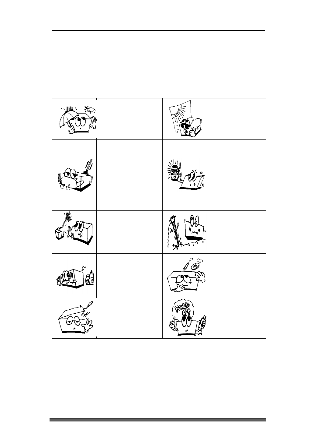
1.4 General Precaution on Environment
Do not keep or operate the equipment under the environment listed below.
Avoid placing in an
area exposed to
moisture. Do not
touch the equipment
with wet hand.
area where there is a
high variation of
temperature.
Operating
temperature ranges
from 10°C to 40°C.
Operating humidity
ranges from 5% to
Avoid exposure to
direct sunlight
Avoid in the
vicinity of Electric
heater
Avoid placing in an
area where there is
an excessive humidity
rise or ventilation
problem.
Avoid placing in an
area where chemicals
are stored or where
there is in danger of
gas leakage.
disassemble the
equipment.
BISTOS Co., Ltd.
does not take
Avoid placing in
an area where
there is an
excessive shock
or vibration.
Avoid dust and
especially metal
material into the
equipment.
the equipment is
not fully installed.
Otherwise, the
equipment could
Page 10
BT-300 Operation Manual 9
P/N : 300-ENG-OPM-EUR-R12
Bistos Co.,Ltd.
2019,07
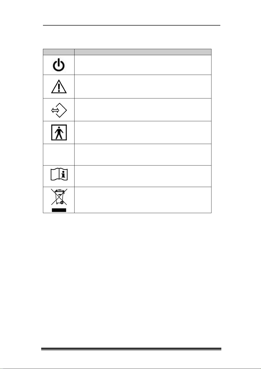
Symbol
Description
This symbol id entifies a safe ty note. Ensur e you understan d the
is unknown hazardous po s sibility by ultrasound.
1.5 Definitions and Symbols
Power On/Off Button
function of this control before using it.
There are no note d or identified hazards by ultrasound. But there
External Signal IN/OUT P ort
Type BF Equipment
IPX8
※ According to IEC 60601-1-6 General requirements for basic safety and essential
performance – Collateral Standard : Usab ility, the d e finition and using these symbols
is adjusted.
IPX8 W a terpr oof
(1 meter of water for 40 minutes.)
Operating instructions
When disposing of some components (ex: internal Li-ion
battery), do not dispose as general wastes.
Adhere to all applicable laws regarding recycling.
Page 11

BT-300 Operation Manual 10
P/N : 300-ENG-OPM-EUR-R12
Bistos Co.,Ltd.
2019,07
WARNING: BT-350 is not intended for use d uring defibrillation, electr o-
Section 2
Introduction
2.1 General
This chapter provides a general description of the BT-300 monitor including:
Brief Device Description
Product Features
Model Configurations
2.2 Brief Device Description
The BT-300 is a microprocessor-based fetal monitor, providing continuous
monitoring, display, and recording of fetal heart rate (FHR) and uterine
contraction (UC) for antepartum tes ting and monitoring.
2.3 Intended Use
The BT-300 is a Prenatal Monitorin g System for non-invasive ly measuring a nd
showing gra phicall y maternal abdominal contractions and the fetal heart rate by
means of display on a non-permanent graphical display and on a strip chart
recorder. This data is intended to aid in assessing the well-being of the fetus
during the fi nal trime ster of pr egnancy (Non-Stress Test). T his device is for use
only by trained medical personnel located in hospitals, cli nics, doctor’s offices
and in the pa tient’s home.
2.4 Product Features
surgery, or magnetic resonance imaging (MRI).
The monitored data can be recorded continuously or intermittently on a strip
chart recorder at the operator’s discretion. The recorded information includes
graphic trend data and text information of monitor hardware and software
configuration, date and time, patient identification, changes to operational
settings, clinician and patient event marks.
Page 12
BT-300 Operation Manual 11
P/N : 300-ENG-OPM-EUR-R12
Bistos Co.,Ltd.
2019,07
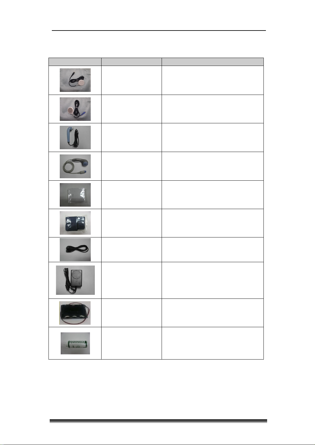
Accessory
Name
Description
2.5 Options and Accessories
Ultrasound T ran sdu cer for Measuring
Doppler Probe
Pressure Sensor (Tocotonometer) for
UC Probe
Event Marker Used for a Fetal Movement event
(IPX8 : Waterp roof)
Measuring Uterine contraction
(IPX8 : Waterp roof)
FHR
AST Probe
(Option)
Z-folded type Paper Z-folder type thermal Paper
Probe Belt
Power Cord AC Power cord
Power Adaptor
LI-ION Battery 14.8V, 2 600mAh
Acoustic Stimulation
Test Probe
Used for Holding Doppler Probe
and/or UC Probe
Adaptor for transform AC Power
(100-240V ~) to DC 18V(2.8A)
Ultrasound Gel
Table 2.1. BT-300 Accesso ries
Ultrasound transmission gel
(Sanipia, ECOSONIC)
Page 13
BT-300 Operation Manual 12
P/N : 300-ENG-OPM-EUR-R12
Bistos Co.,Ltd.
2019,07
① ② ③
④ ⑤⑥ ⑦ ⑧ ⑨ ⑩
⑬
⑫
⑪
⑭
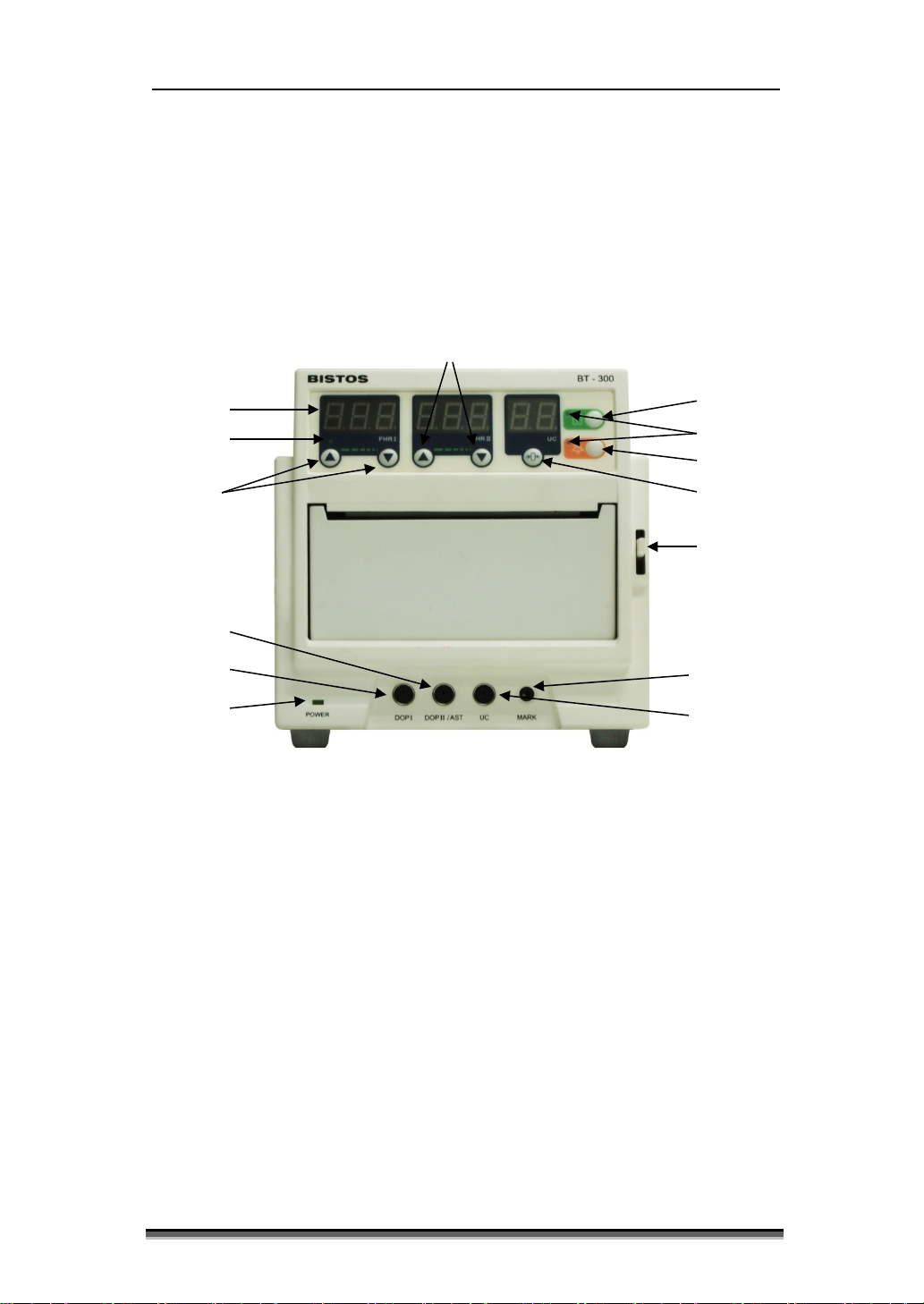
Installation
3.1 Description of the BT-300 Front Panel
Section
3
Fig. 3.1 BT-300 Front Panel
① Power Indicating LED (AC:Green / Battery:Orang e)
② DOP 1 Connector
③ DOP 2 Connector(AST Connector)
④ UC Connector
⑤ Event Marker Connector
⑥ FHR & UC Value Display Panel
⑦ Heartbeat Lamp
⑧ DOP 1 Volume Up/Down Button
⑨ DOP 2 Volume Up/Down Button
⑩ UC Reference Button
⑪ Printer On/Off Button
⑫ Printer & Alarm LED
⑬ Alarm Sound On/Off Button
⑭ Print Door Open Button
Page 14

BT-300 Operation Manual 13
P/N : 300-ENG-OPM-EUR-R12
Bistos Co.,Ltd.
2019,07
① ② ①
②
3.2 Description of the Left Panel
Fig. 3.2 BT-300 Left Panel
① DOP 1 Probe Holder
② DOP 2 Probe Holder(AST Probe Holder)
3.3 Description of the Right Panel
① UC Probe Holder
② Event Marker Holder
Fig. 3.3 BT-300 Right Panel
Page 15

BT-300 Operation Manual 14
P/N : 300-ENG-OPM-EUR-R12
Bistos Co.,Ltd.
2019,07
WARNING: Use only patient cables and transducers supplied with the
① ② ③
④
3.4 Description of the Rear Panel
Fig. 3.4 BT-300 Rear Panel
① Power On/Off Button
② Power Adaptor Jack Connector
③ RS-232C port Connector
④ Speaker
3.5 Power On
When the user wants to turn BT-300 on, power adaptor is connected with
power adaptor jack connector on Rear panel of BT-300 as shown in Figure 3.4
and power button is pressed.
3.6 Patient Cables
The ultraso und and TOCO transducer cable are connected to the front panel.
Each transducer has a label (DOP or UC) to insure pr oper connection to the
exact connector on the monitor. Also each connector in the front panel has a
label (DOP I, DOP II/AST or UC) to insure proper cable connection.
The cables are connected or removed by putting into the c onnector ti ghtly or
pulling out of the connector. There is no connector locking mechanism.
Another ultrasound transducer is supplied with the BT-300 capable of
monitoring two fetuses by connecting this to DOP II/AST connector.
monitor. Use of any other patient cables may result in out-of-specifications
performance and possible safety hazards.
Page 16

BT-300 Operation Manual 15
P/N : 300-ENG-OPM-EUR-R12
Bistos Co.,Ltd.
2019,07
WARNING: Do not connect to an electrical outlet controlled by a wall
switch.
WARNING: SHOCK HAZARD — Power receptacle must be a three -slot
with a three -slot grounded outlet before attempting to operate the monitor.
WARNING: Do not connect to an electrical outlet controlled by a wall
switch.
WARNING: SHOCK HAZA RD — Do not attempt to connect o r disconnect
3.7 Event Marker Cable
The event marker cable is connected to the connector in the fro nt panel. The
label on the housing shows the location of the connector. The cable is
connected b y putt ing int o the connec tor t ightl y. The re is no co nnector locki ng
mechanism.
grounded out let. If the o ut let has onl y two slot s, make sure that it is repla ced
a power cord with wet hands. Make certain that your hands are clean and dry
before touching a power cord.
Page 17

BT-300 Operation Manual 16
P/N : 300-ENG-OPM-EUR-R12
Bistos Co.,Ltd.
2019,07
Configuration parameter
Mode Key
Factory Default
Fetal Heart Rate Lower Alarm Limit
130 BPM
Record Paper Speed
30 mm/min
Fm Prn
(Fetal Movement Graph Print)
Auto Print
0
(Dop2) Offset
0
Prn EnL(Zoom Function)
OFF
Item
Mode Key
Setup Menu
Details
hi
Heart Rate Upper Alarm Limit
Lo
Heart Rate Lower Alarm Limit
yEar
Year
month
Month
SEcond
Second
SPEEd
Record Speed (10, 20, 30mm/min )
Fm Prn
Fetal Movemen t Print
auto P
Auto Print
Section 4
BT-300 Operation
4.1 System Startup
4.1.1 Configuration Settings
The monitor has several configuration settings that the user can change. Some of
these settings are reset to the default value each time the monitor is powered
down. Other parameter settings are saved in the monitor until the next time the y
are changed. These parameters are unaffected when the monitor is powered
down. A complete list of these parameters is shown below.
Fetal Heart Rate Upper Alarm Limit
Alarm
&
Date
Print
Alarm
UC
Reference
datE Date
hour Hour
minut Minute
oFFSEt Dop2 Offset (+20 bpm recording)
Prn EnL Record Enlarge(Zoom)
Alarm
UC
Reference
190 BPM
OFF
Page 18

BT-300 Operation Manual 17
P/N : 300-ENG-OPM-EUR-R12
Bistos Co.,Ltd.
2019,07
Turn on the monitor and keep the alarm
button depressed until the setup items appear
in the FHR display. Pressing the DOP1
volume button, you can change the setup
menu and usi ng by DOP2 volume button, you
can change t he setup value.
Pressing the DOP2 volume button for more
than 2 seconds causes the setting value and
display to increment (or decrement)
continuously for as long as the button is
pressed. When the parameter is set, press the
printer button to save a nd exit the setup mode.
If you press the alarm button for more than
two seconds, you can set the alarm range and
date values. If you press the DOP2 volume
up/down button, you can change the alarm
high limit value. The alarm range is 35 ~
235bpm and, if the upper limit value(or the
lower limit value) is lower(or gre a te r) than the
lower limit value(or the upper limit value ),
the setting va lues do not change. If you press
the DOP1 vo lume d o wn butto n, e nter the ne xt
menu year, month, da te, hour, minute, second
sequentially. And you can change the value
by pressing the DOP2 volume button.
If you press the UC Re fere nce pus hbut ton fo r
more than t wo seconds, you can set the print
values. In pr int setti ng menu, you can c hange
the record speed to one of the three choices,
10, 20, 30mm/minute. The “Fm Prn” function
is activated, the fetal movement graph is
printed on the paper. In “auto P” menu, you
can change the record auto-printing period to
one of the 7 choices, 0(Continuous), 10, 20,
30, 40, 50, 60 minutes. When you want to
measure twin’s heart rates simultaneously,
because the FHR patterns are in the same
range, it makes you tro uble to di stinguish t he
FHR patterns. By enabling the “oFFSEt”
function, the Dop2 heart rates will be printed
plus by 20b pm. Next the “Prn EnL” functions,
you can activate a zoom in function that
printed 74 ~ 200 bpm range.
4.1.2 Understanding and Setting Alarms
The BT-300 monitor has the capability to alert the caregiver in the event a heart
rate goes above or below an alarm limit for a preset time delay.
Page 19

BT-300 Operation Manual 18
P/N : 300-ENG-OPM-EUR-R12
Bistos Co.,Ltd.
2019,07
Activity
Desired Result
[ ]Button Press
To enter the s etup menu over 2 seconds.
[ ] FHR1Button Press
To select “UPPER LIMIT,” “LOWER LIMIT.”
To change the desired value.
Heart Rate Upper
Limit-5) BPM, 1 BPM increments}
[ ]Button Press
Activity
Desired Result
[ ]Button Press
To select “Print Speed”, “Fetal Movement Print”,
Enlarge”
[ ] FHR2Button Press
The list below shows the values that are available
Record Enlarge {ON or OFF}
[ ]Button Press
To save and exit setup menu.
The limit values are configurable. These limit values have no significant
meaning in clinical uses. To prevent overwrapping of limit value, there is an
apartness of upper or lo wer limit by 5 bpm. The purpose of setting for the limit
values is to give accommodation to user. But the delay from onset to alert is
fixed to 20 seconds. If alert situation is continued over 20 seconds, an alarm
event results in an audible tone.
Pressing the alarm button on the monitor’s keypad can silence the alarm tone.
Alarms are enabled or disabled by pressing the alarm on/off button. If alarms are
disabled then all alarms are off. If alarms are enabled then all alarms are on. The
following section describes the procedure used to set alarm parameters for
ultrasound heart rates.
[ ] FHR2Button Press
The list below shows the values that are available
for each parameter:
Heart Rate Upper Limit {(Heart Rate Lower Limit
+10) ~ 235 BPM, 1 BPM increments}
Heart Rate Lower Limit {35 ~ (
To save and exit set up me nu.
4.1.3 Setting [Print Speed / Fetal Movement Print / Auto Print / Dop2
Offset / Record Enlarge]
This section describes the procedure used to set the paper speed and auto stop
time.
When ultrasound trace separation is enabled, the trend data for ultrasound
channel 2 is shifted up by 20 BPM in printing. This fe at ure is p r o vid ed to c lea r l y
see separate heart rate trends when both heart rates are similar. The heart rate
value shown in the numeric frame is not affected. When fetal movement is
enabled, fetal movement graph is printed. FM1 graph is printed in upper
area(50~100 in UC graph Frame), and FM2 graph is in lower area(0~50 in UC
graph Frame ). When follo w the steps below to change the US graph separation
setting.
To enter the setup menu over 2 seconds.
] FHR1Button Press
[
“Auto Print”, “DOP2 OFFSET”, “Record
for each parameter:
Print Speed {10, 20, 3 0 mm/minute}
Fetal Movement Print {ON or OFF}
Auto Print{0, 10, 20, 30, 40, 50, 60 minute}
Dop2 Offset {0 BPM,” or “20 BPM.}
Page 20

BT-300 Operation Manual 19
P/N : 300-ENG-OPM-EUR-R12
Bistos Co.,Ltd.
2019,07
Activity
Desired Result
[ ]Button Press
[ ] FHR1Button Press
To select Time Menu.
[ ] FHR2Button Press
To change the desired value.
Second {0 ~ 59 Second}
[ ]Button Press
FHRⅠFrame
FHRⅡFrame
UC Frame
Alarm
Print
4.1.4 Setting Time and Date
This section describes the procedure used to change the time and date settings of
the monitor.
To enter the setup menu over 2 seconds.
The list below shows the values that are available
for each parameter:
Year {1 ~ 99 Year}
Month {1 ~ 12 Month}
Date {1 ~ 31 Date}
Hour {0 ~ 23 Hour}
Minute {0 ~ 59 Minute}
To save and exit setup menu.
4.2 BT-300 Monitor Display Screen
Symbol Name Description
4.2.1 FHR I & II Frame (Fetal Heart Rate Numeric Frame)
FHR I & II frames display the fetal heart rate and heart icon. And in this frame,
the volume buttons are provided to change speaker volume for setting for the
fetal echo sounds. Using these buttons, user can change speaker volume. This
channel is labeled “FHR I” and “FHR II”. The heart rate value shows the most
recent calculated fetal heart rate. The heart rate icon blinks at the measured heart
rate interval when a valid rate is present.
Fig. 4.3 FHR & UC value display panel
Heart Rhythm
Icon
Alarm Sound Icon Indicating of Alarm sound enable/disable
Print Icon Indicating of a printing status
Blinking ac cording to heart rate
Page 21

BT-300 Operation Manual 20
P/N : 300-ENG-OPM-EUR-R12
Bistos Co.,Ltd.
2019,07
Symbol
Name
Description
fetal audio
fetal audio
Makes the alarm sound enable or disable in
CAUTION: Never use sharp or pointed objects to operate the front-panel
buttons.
4.2.2 UC Frame (TOCO Numeric Frame)
This frame contains the numeric value from the UC transducer representing
uterine contraction. This fra me also shows the present UC baseline value.
4.2.3 The error and current operation message display
FHR I & II and UC frames show the error and current operation status. The error
message will be displayed when the monitor is unable to operate properly. If this
error message shows, discontinue use of monitor.
Message Description
DOP1 is not connected
while BT-300 is monitoring
DOP2 is not connected
while BT-300 is monitoring
Print door is opened while BT-300 is printing
Paper is not loaded while BT-300 is printing
Battery’s charging level is low
while BT-300 is monitoring
4.3 BT-300 Monitor Controls and Indicators
There are seven buttons located on the front panel. The buttons are activated by
pushed with the finger until an audible click is heard.
The operation of the buttons is summarized below.
Dop1 Volume
Up/Down Button
Dop2 Volume
Up/Down Button
UC Reference
Alarm On/Off
Button
Button
Decreases or increases Dop1
volume in monitoring mode.
Decreases or increases Dop2
volume in monitoring mode.
Resets the UC baseline in monitoring mode.
monitoring mo d e.
Record On/Off
Button
Turns the record on or off.
Page 22

BT-300 Operation Manual 21
P/N : 300-ENG-OPM-EUR-R12
Bistos Co.,Ltd.
2019,07
①
③
CAUTION: When loading paper, the paper must be put side upward.
Section 5
Recorder Operation
5.1 Loading Paper
The paper is loaded by pulling down the lever to open the door. Unwrap a pack
of paper and put it into the paper tray.
Several pages from the top of the pack of paper should drape forward over the
shaft of the recorder. The orientation of the paper is with the printed grid facing
up (unfolding from the top of the pack) and the UC grid area right side. The
recorder is now ready for use.
Otherwise, the paper will not be printed.
②
④
Fig. 5.1 Loading Paper
Page 23

BT-300 Operation Manual 22
P/N : 300-ENG-OPM-EUR-R12
Bistos Co.,Ltd.
2019,07
Press Event marker
woman)
When pregnant
movement
FM1 Trace
automatic)
When the syst em
movement(FM1)
FM2
automatic)
When the syst em
movement(FM2)
5.2 Operation
Print On/Off button — A single press and release of [
the recorder mode bet ween printing and nonprinting.
The printer LED in on when the paper is loaded correctly and the printer is
operating. The printer LED is off when the printer is off. If there is no paper, “no
paper” alarm will be displayed and alarm sounds.
Paper Advance — [
A press and hold of this button will advance the recorder paper at high speed
until the button is released. T he r e c order will resume its original activity when
the button is released. This function is ignored during recording. When the
record is finished, the paper feeding function is performed automatically during
short time.
The below is s hown the pri nting parameters.
Symbol Description Source of mark Possible events
Detection Mark
Detection Mark
] button is also used to fast-forward the recorder paper.
Event Mark
FM1
FM2
(by pregnant
(by algorithm and
(by algorithm and
] button will toggle
woman feels fetus
detect fetus
detect fetus
AST Mark
AST
(by doctor)
When the syst em
detect AST signal
Page 24

BT-300 Operation Manual 23
P/N : 300-ENG-OPM-EUR-R12
Bistos Co.,Ltd.
2019,07
CAUTION: Dur ing the usin g BT-300, we do not intend that the cable of
Section 6
Monitoring Fetal Heart Rate
6.1 Electromagnetic Interference
Certain strong electromagnetic fields can interfere with the ultrasound transducer
and cause a false heart rate reading that does not originate from the patient. This
interferenc e i s r ar e, and usually found i n t he vi ci ni t y of l ar ge mac hi ne r y. I n o rd e r
to avoid the possibility of the se interfering signals being misinte rpreted as fetal
heart rates, the following procedure should be followed whenever the monitor is
to be used in a new location, or if it is known that electric al machinery is being
operated in the vicinity.
After connecting the ultrasound transducer(s), turn on the monitor and observe
the heart rate indications on the display for 30 seconds. Intermittent display of
random heart rates is acceptable. However, if there is a constant display of a
physiological heart rate lasting more than 5 seconds, this is an indication that
there is a source of electromagnetic interference in the vicinity. The following
steps should be taken to determine if it is possible to use the monitor in this
environment.
Move all line cords and line-powered equipment at least 6 feet away from
the BT-300. Che ck for exten si on co rd s runnin g behi nd or und er t he bed and
equipment in adjacent rooms. If the artifact heart rate indication ceases, the
monitor may be used normally.
Remove the line cord from the monitor’s power supply. If the artifact heart
rate indication ceases, the monitor may be used normally.
If these measures do not result in ces sation of the heart rate ar tifact, the monitor
cannot be safely used in this environment.
Fetal heart rate is measured by placing an ultrasound transducer on the maternal
abdomen and by processing the Doppler echo signal to produce a heart rate and
an audio representation of the echo signal.
DOP sensor contacts to the patient. To prevent that the cable contacts to
the patient, please cover the patient’s abdomen section which have a
possibility of contacting by the cable with cleaned gauze or fabric.
Step 1: Preparing the Monitor
Turn the mo nitor on and veri fy that the disp lay is normal. Remove the monitor
from service if an error occurs.
Page 25

BT-300 Operation Manual 24
P/N : 300-ENG-OPM-EUR-R12
Bistos Co.,Ltd.
2019,07
CAUTION: The material safe ty data sheet of ultrasound gel is pro vided by
Determine whether the monitor is powered from the internal battery or the AC
power. If operating on the internal battery, check the battery status to determine
whether the battery has suf ficient charge to complete the monitoring session. Use
the AC power if the “low battery” alarm is displayed.
Check the ul trasound transdu cer to ver ify prope r attach ment to the monitor. For
twins monitoring, make sure the second ultrasound transducer is properly
connected.
Adjust heart rate channel one speaker volume to mid-level. Adj ust channel t wo
speaker volume to off if monitoring t wins.
Apply ultrasound gel to the face of the transducer.
Step 2: Acquiring the Fetal Heart Signal
Determine the location of the fetal heart using palpation or a fetoscope. Place the
transducer on the maternal abdomen and listen for the fetal heart signal.
Reposition the transducer for the loudest fetal heart signal and verify the heart
shape icon on the screen is blinking at the fetal heart rate.
Secure the ultrasound transducer with the elastic belt. Make sure the transducer
is still positioned for the loudest fetal hea r t signal.
Verify the monitor is displaying fetal heart rate values and that the heart shape
icon on the display is blinking at the measured heart rate.
Step 3: Acquiring Twins’ Heart Rates
Follow the steps outlined in step 2 above to acquire the heart rate for the first
fetus.
Adjust the ultr a so und a ud io v ol ume for channel one down and channel two up so
that the second heart sounds can be heard.
Determine the location of the second fetal signal using palpation or fetoscope.
Apply gel to the second ultrasound transducer and place it on the maternal
abdomen where the second fetal signal was located. Adjust the position of the
transducer to find the fetal signal and to maximize its loudness.
Secure the ultrasound transducer with the elastic belt. Make sure the transducer
is still positioned for the lou dest fetal heart signal. Also verify the position of
transducer one has not changed.
Verify the monitor is d isplaying fetal hear t rate val ues for b oth fetuses a nd that
the heart shape icons both on the display are blinking at the measured heart rate.
the manufac turer of ultrasoun d gel. Therefore usi ng the gel is safe for t he
patient. But unexpected side effects can be caused by different patients. To
minimize unexpected side effects, please do not use the gel for man y hours.
Page 26

BT-300 Operation Manual 25
P/N : 300-ENG-OPM-EUR-R12
Bistos Co.,Ltd.
2019,07
Doppler Probe
Step 4: Monitor Adjustments
Readjust the volume settings for the desired loudness.
6.2 Detail Procedure
① Explain procedure to the patient.
② Place a probe belt under the patient.
③ Turn the monitor p ower on. The po wer switch is locate d on the rear panel.
The green indicator located on the front panel when the powe r on.
④ Determine the position of the fetus using Leopold’s maneuvers. The
strongest fetal heart tones are heard through the fetal back.
⑤ Plug the ultrasound transducer cable into the connector labeled “DOP I” or
“DOP II/AST”.
⑥ Apply a small amount of ultrasonic coupling gel to the face of the transducer.
⑦ Place the transducer face down on the maternal abdomen over the area
determined to be the fetal back.
⑧ Secure the transducer comfortably in the place by inserting the transducer
button through the buttonholes on each end of the be lt.
⑨ Volume Up/Down button may be used to adjust the volume.
⑩ Reposition the transducer as necessary until the clearest heart sound is heard.
Three to five seconds after a clear heart beat sound is heard, the heart shaped
indicator will flash synchronously with the sound. This indicates signal
acceptance and recording.
Figure 6.1 the direction of Doppler Probe
Page 27

BT-300 Operation Manual 26
P/N : 300-ENG-OPM-EUR-R12
Bistos Co.,Ltd.
2019,07
⑪ If the printer is not already activated, press the [ ] button located on the
front panel of the monitor. The recorder plots the FHR on the paper strip
chart.
Figure 6.2 Positioning of UC Probe
Page 28

BT-300 Operation Manual 27
P/N : 300-ENG-OPM-EUR-R12
Bistos Co.,Ltd.
2019,07
CAUTION: Dur ing the usin g BT-300, we do not intend that the cable of
Section 7
Uterine Contraction (UC)
Uterine contraction is measured externally by placing a pressure sensitive device
(Tocotonometer) on the maternal abdomen and recording relative pressure changes.
UC sensor contacts to the patient. To prevent that the cable contacts to the
patient, please cover the patient’s abdomen section which have a
possibility of contacting by the cable with cleaned gauze or fabric.
Step 1: Preparing the Monitor
Turn the mo nitor on and veri fy that the disp lay is normal. Remove the monitor
from service if an error occurs.
Determine whether the monitor is powered from the internal battery or the AC
power. If op erating on t he internal battery, check the battery status to determine
whether the battery has suf ficient charge to complete the monito r ing session. Use
the AC power if the “low battery” alarm is displayed.
Check the UC transducer to verify proper attachment to the monito r.
Check for t he proper se t ting for UC baseline. Adjust as needed.
Step 2: Acquiring Uterine Contraction Data
Place the face (button side) of the UC probe on the fundus o f the uterus when
contractions are not occurring. No gel is required.
Secure the UC probe with the belt. The uterine contraction read ing at this point
should be greater than 30 and less than 90 units. If the readings fall outside this
range, the belt may be too tight or too loose. If the belt is over tightened, the
contraction peaks may have a flat-top at less than 100 on the UC scale. If the belt
is under tightened, the position of the transducer may wander and cause unusable
readings. Readjust the belt pressure as needed.
Step 3: Monitor Adjustments
Press the UC reference button on the front panel to adjust the values to the
baseline. This must be done during non-contraction intervals.
7.1 Detail Procedure
① Explain procedure to the patient.
② Place a probe belt under the patient
Page 29

BT-300 Operation Manual 28
P/N : 300-ENG-OPM-EUR-R12
Bistos Co.,Ltd.
2019,07
③ Turn the monitor power on. The power switch is l ocated on the rear panel. The
green indicator located under the left side of the printer door illuminates when
the power on.
④ Connect the transducer plug to “UC” connector located on the underside of the
front cover.
Note: When connector or re-connecting the tocotransducer to the monitor’s UC
connector, you must wait at least 10 seconds before depressing the UC
reference [ ] button.
⑤ Briefly depress the UC reference [ ] pushbutton to set the UC baseline at 10.
⑥ Position tocotransducer on the maternal abdomen over the uterine fundus or
where there is the least maternal tissue and the contractions are strongly palpated.
⑦ Connect each end of the belt to the transducer by inserting the transducer button
through a buttonhole on the strap. Select a buttonhole that ensure a comfortable
fit and holds the transducer securely in the place.
⑧ Between contractions, depress the UC reference [ ] butto n again. T his set U C
baseline to 10. The monitor is now ready to begin monitoring.
⑨ If the pr inter is not already activated, depress the [ ] button located on the
front panel of the monitor. The recorder plots the UC on the paper strip chart.
CAUTION: The probe belt may cause allergy or skin side effects to patient, if it
is used so long time.
Page 30

BT-300 Operation Manual 29
P/N : 300-ENG-OPM-EUR-R12
Bistos Co.,Ltd.
2019,07
Section 8
Event Marker
8.1 Event Marker
The event marker arrow is provided so that the patient can record the time of
important events. The patient merely presses the marker button located on the
end of the marker cable at the time an event occurs. The event marker icon by
patient’s press is an up ward pointing a rrow. A strip chart printout of the patient
record will also show this mark.
Page 31

BT-300 Operation Manual 30
P/N : 300-ENG-OPM-EUR-R12
Bistos Co.,Ltd.
2019,07
WARNING: Unp lug the moni tor from the AC p ower source and detach all
enter the case.
CAUTION: Take extra care when cleaning the display surfaces, which are
sensitive to rough handl ing. Rub the lens that cover s them with a soft, dry cloth.
CAUTION: Do not autoclave. Does not gas or sterilize.
CAUTION: Do not immerse in liquid. When using solutions, use ster ile
Section 9
Cleaning and Disinfection
This chapter contains instructions for the care and cleaning of the BT-300 unit and its
accessories.
The BT-300 requires proper care and preventive maintenance. This ensures consistent
operation and maintains the high level of performance necessary in monitoring
procedures.
9.1 Monitor
Keep the external surface clean and free of dust, dirt, and residual liquids.
Clean with a damp cloth using mild soap and water or hospital approved,
nonabrasi ve disinfectants.
accessories before cleaning. Do not immerse the unit in water or allow liquids to
9.2 Transducers
Cleaning and Disinfecting the Tocotonometer and Ultrasound
Transducer
To avoid damage to the transducers, clean and disinfect only according to the
following instructions. Care MUST be taken to preserve both the
Tocotonometer label and the Tocotonometer cable label. DO NOT remove,
conceal or deface Tocotonometer labels.
1. Wipe the device with a sterile wipe soaked in enzymatic detergent s afe for
use with metal instruments. Wipe the exterior of the device three times.
Prepare the detergent according to the manufacturer’s transducer
recommendations.
2. Scrub the transd ucer with e nzymatic deterge nt using so ft bris tled brus h for
five (5) minutes..
wipes to avoid pouring fluids directly on the transducer.
3. Wipe the transducer three (3) times with sterile water to remove soap
residue.
4. Wipe the transducer with a sterile wipe soaked in Cidex™. Wipe a ll
exterior surfaces of the transducer three (3) times.
5. Wipe the transducer three (3) times with sterile water to remove Cidex
Page 32

BT-300 Operation Manual 31
P/N : 300-ENG-OPM-EUR-R12
Bistos Co.,Ltd.
2019,07
Contacting
component
DOP enclosure
ABS AV20F
Must be cleaned and
disinfected prior to use
UC enclosure
ABS AV20F +
S385A-46N
Must be cleaned and
Manufacturer
Active
Sterilant Contact
High Level
Contact Conditions
K924434 Cidex™ Activated Dialdehyde Solution
Johnson & Johnson
2.4%
10 hrs at 25°C
Test only.
45 min at 25°C
CAUTION: The water temperature must not exceed 60°C (140°F).
residue.
6. Dry the device thoroughly with a sterile soft towel or gauze surgical sponge.
7. Wrap the dry device in a fresh sterile so ft towel or transparent sterile wrap
for storage until next use.
9.3 Belts
Wash soiled belts with soap and water.
9.4 Contacting components and characteristics
Material Usage Disinfection
Reusable
Polyurethane ESTANE
9.5 Description of Cidex
1. Cidex
2. FDA-Cleared Sterilants and High Le vel Disinfectants with General Claims
Medical Products
TM
is FDA-cleared for use in the United States. Therefore we suggest
that the disinfection effect using Cidex
for Processing Reusable Medical and Dental Devices – March 2009
(www.fda.gov/MedicalDevices/DeviceRegulationandGuidance/Reprocessi
ngofSingle-UseDevices/UCM133514)
Ingredient
glutaraldehyde
TM
Reusable
TM
is valid.
Conditions
14 days Maximum
Reuse Contact
conditions based
on AOAC
Sporicidal Activity
disinfected prior to use
Disinfectant
14 days Maximum
Reuse Contact
conditions based on
literature
references.
Page 33

BT-300 Operation Manual 32
P/N : 300-ENG-OPM-EUR-R12
Bistos Co.,Ltd.
2019,07
External:
Power Adaptor
Input : AC (100-240V), 50~60Hz
Output: DC(18V), 2.8A
Internal:
Li-ion, rechargeable battery
Power
AC -powered:
80 W, maximum
Battery -powered
80 W, maximum
1-hour battery operation when fully charged at 25℃
Operating Temperature:
10 °C to 40 °C (50 °F to 104 °F)
Operating Humidity
5 to 85% non-condensing
Storage Temperature:
- 20 °C to 60 °C (-4 °F to 140 °F)
Storage Humidity:
0 to 95% non-condensing
Altitude:
Pressure
0 -2000m (0 -6,561.68 ft)
70kPa ~ 106kPa
Parameter
Value
FHR Range:
30-240 BPM
Accuracy:
±2% of range
Leakage:
<10 µA @ 264 VAC applied to transducer
Isolation:
>4 kV RMS, Type BF applied part
Parameter
Value
UC Range:
0-99 relative units
Resolution:
1 Count
Section 10
Specifications
BT-300 Monitor Specifications:
Physical Characteristic s
Dimensions – 19.1 cm H x 18.7 cm W x 20.1 cm D
Weight - approx. 5.0 kg
Safety
Complies with IEC 60601-1, IEC 60601-1-2, IEC 60601-2-37
Class I Equi pment & Internal Powered Equipment
Continuous Operation
Type BF applied parts
Doppler / UC Probe : IPX8
Power
Dissipation:
Environmental
Doppler Ultrasound FHR Monitoring
Uterine Contraction (TOCO) Monitoring
Page 34

BT-300 Operation Manual 33
P/N : 300-ENG-OPM-EUR-R12
Bistos Co.,Ltd.
2019,07
Accuracy:
±1% relative unit
Leakage:
<10 µA @ 264 VAC applied to transducer
Isolation:
>4 kV RMS, Type BF applied part
Pack Style:
Z-Fold.
Pack Size:
130 mm x 120 mm x 20 mm
End-of-Pack:
Mark along paper edge
Loading:
Front-door, slide-in
Paper Detectors:
Paper Out
Loading Door Open
Paper
Paper Speeds
Normal: 1, 2, and 3 cm/min ±1%
High-Speed: 50 cm/min
Paper Tracking Accuracy: ±1% (exclusive of paper accuracy)
Page 35

BT-300 Operation Manual 34
P/N : 300-ENG-OPM-EUR-R12
Bistos Co.,Ltd.
2019,07
Acoustic
I
(mW/cm2)
I
(mW/cm2)
Global Maximum Value
0.04
17.6
0.396
P
r.3
(MPa)
0.063685
W
(mW)
16.7*
16.7*
f
(MHz)
0.985
0.985
0.985
Z
(cm)
2 2 2
Beam
x
(cm) 0.6
0.6
y
(cm) 1.3
1.3
PD (µsec)
128 128
PRF (Hz)
3472
3470
EBD
Az.(cm) 1.1
Ele.(cm) 1.1
Control 1
Default
Default
Default
Control 2
Control 3
Control 4
Control n
Acoustic Output Reporting Non-Auto scanning Mode
Operating Mode : PW Mode
Associated
Acoustic
Parameter
Output
0
c
sp
dimensions
MI
-6
-6
SPTA.3
SPPA.3
Mode
Operating
Control
Conditions
Mode
Mode
- *Measured values were multiplied by nine to account for nine
elements in the transducer.
- Ultrasonic Power = 16.7 mW
- Ultrasonic element diameter = 1.1cm
-
Duty Factor(DF) =Pulse Duration x Pulse Repetition Frequency = 128 x 10-6 x 3,472 =
0.444416
-
Area correspondin g to entrance b eam dimensions = 9 x 3.14 x 0.552 = 8.54865
2
cm
-
I
@ Transducer Face = Ultrasonic Power / Area Corresponding to entrance
SATA
beam dimensions = 16 .7 / 8.54865 = 1.95352482555725
≒
1.95 mW/cm2
-
I
@ Transducer Face
SAPA
4.4 mW/cm
2
= I
@ Transducer Face / DF = 1.95 / 0.444416 ≒
SATA
Page 36

BT-300 Operation Manual 35
P/N : 300-ENG-OPM-EUR-R12
Bistos Co.,Ltd.
2019,07
Section 11
Troubleshooting and
Maintenance
11.1 User Test
The user has t o check the monitor performances each time the unit i s turned on.
1. Make sure the monitor power is properly connected.
2. Check the recorder for paper and door open.
3. Connect the transducers to the monitor.
4. Turn on the monitor.
Check that the monitor successfully powered on and is displaying the LED
window. If an error occurs , the unit should be removed from service if this
occurs.
Check that the recorder is feeding paper and the power on test pattern printed
properly. Remove from service if this does not occur.
11.2 Ultrasound Transducer Test
To test an ultrasound transducer:
1. Properly connect the transducer to the front panel.
2. Turn on the monitor.
3. Adjust the speaker volume to an audible level.
4. Hold the transd ucer o n one ha nd and ta p on the tra nsduc er fac e with t he other
hand. The tapping sound should be heard from the monitor.
The transducer is operating properly if you can hear noise from the speaker.
Remove from service if no noise is heard or until the proper cause is identified
and repaired.
11.3 UC(TOCO) Test
To test the UC(TOCO) transducer:
1. Properly connect the transducer to the front.
Page 37

BT-300 Operation Manual 36
P/N : 300-ENG-OPM-EUR-R12
Bistos Co.,Ltd.
2019,07
CAUTION: The internal battery must be handled by the company’s
technician only. Do not attempt to open the BT-300.
2. Turn on the monitor.
3. Gently apply pressure to the button centered on the face of the transducer.
The displa y and printout sho uld show a chan ge in pressure i f the transducer is
operating properly. Remove from service if this does not occur.
11.4 Battery Disposal and Handling
CAUTION: When disposin g of internal Ni-MH battery, adhere to all applicable
laws regarding recycling. Avoid storing battery above 140°F. If clothing or skin
comes in contact with material fro m inside the battery, immediately wash with
plenty of clean water.
The internal battery is consumables. Therefore the operation time by the battery
can be decreased. If the operation time is not long enough, please contact service
center and c ha nge t he b atte r y. If this system is used with not suf ficient oper ating
time by the internal battery, it is possible to be shut down the system because o f
the lack of the internal battery’s capacity. This situation can cause not intended
stop of measuri ng a nd moni t o ri ng function.
11.5 Maintenance
The BT-300 monitor and accessories require no periodic calibration or
adjustment. The recommended interval for performing hipot and leakage testing
is once per year.
11.6 Disposal of the BT-300
When disposing of the BT-300, adhere to all applicable laws regarding
recycling. If you are not able to dispose the BT-300 or you need a help for
disposing the BT-300, please contact us. In the case of there are no appropriate
ways to dispose, we will pick up the BT-300 for you.
11.7 Request a service for general problems
If the main body or accessories are damaged by excessive mechanical forces,
narrow cracks or separation of internal ultrasonic sensor can be happened.
These can be checked through visible or auditory decision. These can cause
malfunction some times. But these do not cause unacceptable risks. If the BT300 does not work properly, please contact us and change the corresponding
parts. Note that the replacement costs can be occurred.
Page 38

BT-300 Operation Manual 37
P/N : 300-ENG-OPM-EUR-R12
Bistos Co.,Ltd.
2019,07
The BT-300 is intended for use in the electromagnetic environment specified below. The customer of the
user of the BT-300 should as sure that it is used in such an environment.
Emission test
Compliance
Electromagnetic environment - guidance
RF emissions
Group 1
The BT-300 uses RF energy only for its internal function.
cause any in terference in n earby electronic equipment.
RF emissions
CISPR 11
Class A
NOTE: The EMISSIONS characteristics of this equipment
350 is suitable for use in all establishments other
than domestic, and may be used in domestic establishments
supply network that supplies buildings used for domestic
professionals only. This equipment/system may cause radio
interference or may disrupt the operation of nearby
location.
Harmonic emissions
IEC 61000-3-2
Class A
Voltage fluctuations /
Complies
The BT-300 is intended for use in the electromagnetic environment specified below. The customer or the
user of the BT-300 should as sure that it is used in such an environment.
Immunity T e st
IEC 60601
Test level
Compliance
level
Electromagn etic environment guidance
Electrostatic
± 8 kV contact
± 8 kV contact
Floors should be wood,
concrete or ceramic tile. If
floors are covered with
synthetic material, the relative
30%.
Electrical fast
± 2 kV for power
output lines
± 2 kV for power
output lines
Mains power quality should be
Surge
± 1kV power
signal lines
± 0.5kV, ± 1kV power
signal lines
Mains power quality should be
Voltage dips,
variations on
power supply
IEC 61000-4-11
70%U
70%U
Mains power quality should be
hospital environment. If the
operation during power mains
interruptions, it is
recommended that the [ME
Equipment or ME System] be
Section 12
Manufacturer’s Declaration
12.1 Electromagnetic emissions
CISPR 11
flicker emissions
IEC 61000-3-3
12.2 Electromagnetic immunity
Therefore, i t s RF emi ss i on s a re v er y low an d a re n ot li k ely to
make it suitable for use in industrial areas and hospitals
(CISPR 11 class A).
The BT-
and those directly connected to the public low-voltage power
purposes, provided the following warning is heeded:
Warning: Thi s BT-350 is intended for use by healt hcare
equipment . It may be necess ary to take mi tigation measures,
such as re-orienting or relocating the BT-350 or shielding the
discharge(ESD)
IEC 61000-4-2
transient/burst
IEC 61000-4-4
IEC 61000-4-5
short
interruptions and
voltage
input lines
(50/60Hz)
± 15kV air
supply lines
± 1kV for input /
differential mode
± 2kV
power common mode
± 2kV input / output
T
for 25cycle (50Hz)
70%U
T
for 30cycle (60Hz)
0%U
T
for 0.5cycle
0% U
T
for 1cycle
± 2kV, ± 4kV, ± 8kV,
± 15kV air
supply lines
± 1 kV for input /
differential mode
± 0.5kV, ± 1kV, ±2kV
power common mode
± 2kV input / output
T
for 25cycle (50Hz)
70%U
T
for 30cycle (60Hz)
0%U
T
for 0.5cycle
0% U
T
for 1cycle
humidity should be at least
that of a typical commercial or
hospital environment.
that of a typical commercial or
hospital environment.
that of a typical commercial or
user of the [ME Equ ipment or
ME System] r equ i res con ti nu ed
Page 39

BT-300 Operation Manual 38
P/N : 300-ENG-OPM-EUR-R12
Bistos Co.,Ltd.
2019,07
0% UT
for 300cycle (60Hz)
0% UT
for 300cycle (60Hz)
powered from an
Power frequency
30 A/m
30 A/m
Power frequency magnetic
fields should be at levels
characteristic of a typical
location in a typical
commercial or hospital
environment.
Note UT is the a.c. mains voltage prior to application of the test level.
The BT-300 is intended for use in t he electromagnetic environment specified below. The customer or
the user of the BT-300 should assure that it is used in such an environment.
Immunity
test
IEC 60601 test
level
Compliance
level
Conducted
3 Vrms
3 Vrms
Portable and mobile RF communications
equipment should be used no closer to any
300, including cables, than the
from the equation applicable to the frequency
of the transmitter in watts (W) according to
is the
should be less than the compliance level in
Interference may occur in the vicinity of
equipment marked with the following
NOTE 1 ) At 80 MHz and 800 MHz, the higher frequency range applies. NOTE 2) These guidelines
from structures, objec ts and people.
a
Field strengths from fixed transmitters, such as base stations for radio (cellular/cordless) telephones
transmitters, an electromagnetic site survey should be considered. If the measured field strength in the
Over the frequency range 150 kHz to 80 MHz, field strengths should be less than [V1] V / m.
(50/60Hz)
magnetic f ield
IEC 61000-4-8
RF
IEC 610004-6
Radiated RF
IEC 610004-3
150 kHz to
80MHz
(AM 80%, 1kHz
sine-wave)
6 Vrms
150 kHz to
80MHz
(AM 80%, 1kHz
sine-wave)
3 V/m
80 MHz to 2.7
GHz
(AM 80%, 1kHz
sine-wave)
9 ~ 28 V/m
385MHz to
6GHz
(FM, ±5kHz
deviation 1kHz
sine)
(PM, 50%
18/217Hz)
for 250cycle (50Hz)
0% U
T
150 kHz to
80MHz
(AM 80%, 1kHz
sine-wave)
6 Vrms
150 kHz to
80MHz
(AM 80%, 1kHz
sine-wave)
3 V/m
80 MHz to 2.7
GHz
(AM 80%, 1kHz
sine-wave)
9 ~ 28 V/m
385MHz to
6GHz
(FM, ±5kHz
deviation 1kHz
sine)
(PM, 50%
18/217Hz)
for 250cycle (50Hz)
0% U
T
Electromagnetic environment - guidance
part of the BTrecommended separation distance calculated
of the transmitter.
Recommended separation distance.
where P is the maximum outpu t power rating
the transmitter manufacturer and d
recommended separation distance in meters
(m).
Field strengths from fixed R F transmitters, as
determin ed by an elect romagnetic site surve y,
a
each frequency range. b
symbol :
uninterruptible power supply or
a battery.
80 MHz to 800 MHz
800 MHz to 2.5 G H z
may not apply in all situations. Electromagnetic propagation is affected by absorption and reflection
and land mobile radios, amateur radio, AM and FM radio broadcast and TV broadcast cannot be
predicted theoretically with accuracy. To assess the electromagnetic environment due to fixed RF
location in which the BT-300 is used exceeds the applica ble RF compli ance level abo ve, the BT-300
should be observed to verify normal operation. If abnormal performance is observed, additional
measures may be necessary, such as re-orienti ng or relocating the BT-300.
b
Page 40

BT-300 Operation Manual 39
P/N : 300-ENG-OPM-EUR-R12
Bistos Co.,Ltd.
2019,07
Rated
output power
Separation distance according to frequency of transmitter [m]
150 kHz to 80 MHz
80 MHz to 800
800 MHz to 2.5
V1 = 3Vrms
V2=0.1Vrms
E1=3V/m
E1=3V/m
0.01
0.12
3.50
0.12
0.23
0.1
0.37
11.06
0.37
0.74
1
1.17
35.00
1.17
2.33
10
3.69
110.67
3.69
7.38
100
11.66
350.00
11.66
23.33
For transmitters rated at a maximum output power not listed above, the recommended separation
(m)can be estimated using the equation applicable to the frequency of the
absorption and reflect ion from structures, objects and people.
12.3 Recommended separation distances between portable
and mobile RF communications equipment and the BT-300
maximum
of transmitter
[W]
distance d in meters
transmitter, where p is the maximum output power rating of the transmitter in watts (W) according to the
transmitter manufacturer.
NOTE 1) At 80 MHz and 800 MHz, the separation distance for the higher frequency range applies.
NOTE 2) These guidelines may not apply in all situations. Electroma gnetic propagation is affected by
MHz
GHz
Page 41

BT-300 Operation Manual 40
P/N : 300-ENG-OPM-EUR-R12
Bistos Co.,Ltd.
2019,07
Product Name
Fetal Monitors
Model Name
BT-300
Approval No.
Approval Date
Serial No.
Warranty Period
2 Years (Probe excluded)
Date of Purchase
Hospital:
Telephone:
Sales Agency
Manufacture
Bistos Co., Ltd
Product Guarantee
Customer
Address:
Name:
※ Thank you for purchasing BT-300.
※ This product is manufactured and passed through strict quality control and inspection.
※ Compensation stand ard concerni ng repair, replacement, refund of the product
complies with “Consumer’s protection law” noticed by Economic Planning Dept.
Service Telephone and Fax. Numbers
Telephone: +82 31 750 0340
Fax: +82 31 750 0344
th
FL., A Bldg., Woolim Lions Valley 5-cha, 302, Galmachi-ro,
7
Jungwon-gu, Seongnam-si, Gyeonggi-do, Korea
Bistos Co., Ltd.
www.bistos.co.kr
bistos@bistos.co.kr
Obelis s.a
Bd. Général Wahis 53
1030 Brussels, BELGIUM
Telephone: + (32) 2. 732.59.54
Fax.: + (32) 2.732.60.03
 Loading...