

Page 1
YOU'RE HEARD, LOUD AND CLEAR.
Instruction Manual for
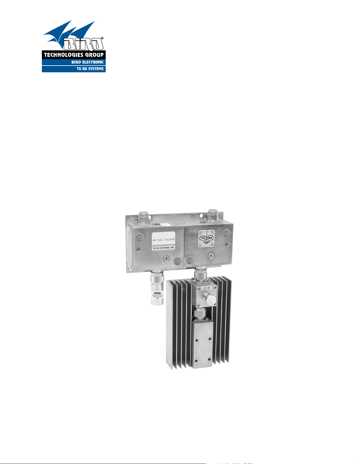
VHF & UHF Dual-Section
Isolators
Manual Part Number
7-9095
8625 Industrial Parkway, Angola, NY 14006 Tel: 716-549-4700 Fax: 716-549-4772 sales@birdrf.com www.bird-technologies.com
Page 2

Warranty
This warranty applies for one year from shipping date.
TX RX Systems Inc. warrants its products to be free from defect in material and workmanship at the time of shipment.
Our obligation under warranty is limited to replacement or repair, at our option, of any such products that shall have
been defective at the time of manufacture. TX RX Systems Inc. reserves the right to replace with merchandise of
equal performance although not identical in every way to that originally sold. TX RX Systems Inc. is not liable for dam-
age caused by lightning or other natural disasters. No product will be accepted for repair or replacement without our
prior written approval. The purchaser must prepay all shipping charges on returned products. TX RX Systems Inc.
shall in no event be liable for consequential damages, installation costs or expense of any nature resulting from the
purchase or use of products, whether or not they are used in accordance with instructions. This warranty is in lieu of all
other warranties, either expressed or implied, including any implied warranty or merchantability of fitness. No representative is authorized to assume for TX RX Systems Inc. any other liability or warranty than set forth above in connection with our products or services.
TERMS AND CONDITIONS OF SALE
PRICES AND TERMS:
Prices are FOB seller’s plant in Angola, NY domestic packaging only, and are subject to change without notice. Federal, State and local sales or excise taxes are not included in prices. When Net 30 terms are applicable, payment is
due within 30 days of invoice date. All orders are subject to a $100.00 net minimum.
QUOTATIONS:
Only written quotations are valid.
ACCEPTANCE OF ORDERS:
Acceptance of orders is valid only when so acknowledged in writing by the seller.
SHIPPING:
Unless otherwise agreed at the time the order is placed, seller reserves the right to make partial shipments for which
payment shall be made in accordance with seller’s stated terms. Shipments are made with transportation charges collect unless otherwise specified by the buyer. Seller’s best judgement will be used in routing, except that buyer’s routing
is used where practicable. The seller is not responsible for selection of most economical or timeliest routing.
CLAIMS:
All claims for damage or loss in transit must be made promptly by the buyer against the carrier. All claims for shortages
must be made within 30 days after date of shipment of material from the seller’s plant.
SPECIFICATION CHANGES OR MODIFICATIONS:
All designs and specifications of seller’s products are subject to change without notice provided the changes or modifications do not affect performance.
RETURN MATERIAL:
Product or material may be returned for credit only after written authorization from the seller, as to which seller shall
have sole discretion. In the event of such authorization, credit given shall not exceed 80 percent of the original purchase. In no case will Seller authorize return of material more than 90 days after shipment from Seller’s plant. Credit
for returned material is issued by the Seller only to the original purchaser.
ORDER CANCELLATION OR ALTERATION:
Cancellation or alteration of acknowledged orders by the buyer will be accepted only on terms that protect the seller
against loss.
NON WARRANTY REPAIRS AND RETURN WORK:
Consult seller’s plant for pricing. Buyer must prepay all transportation charges to seller’s plant. Standard shipping policy set forth above shall apply with respect to return shipment from TX RX Systems Inc. to buyer.
DISCLAIMER
Product part numbering in photographs and drawings is accurate at time of printing. Part number labels on TX RX
products supersede part numbers given within this manual. Information is subject to change without notice.
Bird Technologies Group TX RX Systems Inc.
Page 3
Manual Part Number 7-9095
Copyright © 2006 TX RX Systems, Inc.
First Printing: May 1994
Version Number Version Date
1 05/24/94
2 07/29/99
3 01/17/06
Symbols Commonly Used
WARNING
CAUTION or ATTENTION
High Voltage
Use Safety Glasses
ESD Elecrostatic Discharge
Hot Surface
Electrical Shock Hazard
NOTE
Important Information
Bird Technologies Group TX RX Systems Inc.
Page 4

Page 5
Input Connector
Output Connector
Remove screws to
access tuning
capacitors
Remove stickers
to access tuning
capacitors
Remove stickers
to access tuning
capacitors
Input Section
Load
Output Section
Load
Figure 1: VHF or UHF Dual-Section Isolator.
GENERAL DESCRIPTION
Isolators perform two important functions. Their primary function is to keep other RF frequencies out
of the transmitter so that intermodulation products
cannot be generated. isolators have a substantial
amount of reverse isolation. They also insure that
the transmitter never sees any significant reflected
struction and theories of operation of ferrite isolators refer to the TX RX Systems Inc. publication
“SEMINAR SUBJECTS” titled “An Elementary
Introduction to Ferrite Isolators, Circulators and RF
Loads” (literature number C2003H92). Contact
your TX RX Systems sales representative if you
wish to order a copy.
power so it will always operate with maximum stability at full-power output. Isolators prevent energy
from getting to the transmitters output by dumping
RF energy entering the output of the isolator into a
dummy load.
Dual-Section Isolators
Dual section units have two load ports, one for
each section of the isolator, refer to Figure 1.
Although loads of equal power rating may be used
for both ports, it is customary to use an output load
This manual deals primarily with the procedures
necessary for field tuning ferrite isolators to new
frequencies. It is assumed that procedures in this
manual will be carried out by a skilled electronics
technician who is familiar with the communications
capable of dissipating the maximum expected
reflected power that might be encountered. A small
load (5 watts) is usually installed on the first section
where the high reflected power is not a factor. The
model number on the isolator label indicates the
system. For a more detailed discussion of the con-
TX RX Systems Inc. Manual 7-9095-3 01/17/06 Page 1
Page 6

3.313"
84 mm
0.188"
5 mm
3.125"
79 mm
0.313"
8 mm
1.438"
37 mm
4.688"
120 mm
5.813"
148 mm
3.250"
83 mm
5.500"
140 mm
0.219" (6 mm) Dia
Mounting Holes
4 places
Figure 2: Mounting hole layout.
value of the loads installed. See the specification
charts at the end of this manual.
VHF models maintain their specifications over a
2.5% bandwidth which equals 3.8 MHz at 150
MHz. UHF models have a minimum bandwidth of
1.25% which equals 5.75 MHz at 460 MHz. When
the frequency of operation needs to be changed
by more than about half of the above mentioned
bandwidth figures, tuning of the isolator will ensure
optimum performance.
INSTALLATION
All isolator models may be mounted on most surfaces but should not be located where they will be
exposed to moisture or very high humidity. TX RX
Systems' isolators are well shielded magnetically
and may be mounted on steel cabinets or panels.
A mounting hole layout is shown in Figure 2.
The isolator loads can get quite
hot during operation. This can
occur when an antenna system
component fails causing high
reflected power which is then dissipated by the isolator load.
These loads can get hot enough
to burn skin so use caution when
servicing these devices.
Recommended Test Equipment for Tuning
The following equipment or its equivalent is recommended:
TX RX Systems Inc. Manual 7-9095-3 01/17/06 Page 2
Page 7

+30
+20
+10
-10
-20
-30
0
Analyzer
Input
Generate
Output
+30
+20
+10
-10
-20
-30
0
Analyzer
Input
Generate
Output
RLB - 150 Bridge
Reflected
To device to be tested.
This connector left open
for setting 0 dB reference.
Load
Source
Figure 3: Proper hookup of RLB-150 Bridge.
1) IFR Model A-7550 Spectrum Analyzer/Tracking generator combination or equivalent.
2) Eagle RLB-150 Return Loss Bridge (35 dB
directivity).
3) Double shielded coaxial cable test leads
(RG142 B/U or RG223/U).
4) 50 Ohm load with at least -35 dB return loss
(1.10:1 VSWR).
Bridge
Dual
VHF
Isolator
Loads that will
be used during
actual operation
1
TUNE
5
3
2
6
4
Any good
quality
50 ohm
load
Figure 4: Tuning for maximum return loss.
5) Metal blade tuning tool for adjusting ceramic
and/or piston variable capacitors (TX RX Model
makes this stored trace the zero reference. The
procedure for doing so is outlined below.
# 95-00-01).
Tuning Procedure
It is necessary to be able to set zero references for
both insertion loss and return loss measurements
in order to determine if specifications are being
met. This procedure is not outlined in the A-7550
manual but consists of using the “STORE” trace
function to save the reference trace level and then
putting the A-7550 into the reference mode which
SETTING 0 DB INSERTION LOSS REFERENCE
Set the A-7550 for the desired frequency and
bandwidth. Connect the output and input leads
together through a female barrel connector (UG 29
-N or UG 914 -BNC) and proceed as follows:
1) Make sure that the unit is in “LIVE” mode.
2) From the Mode Menu, “STORE” the trace.
TX RX Systems Inc. Manual 7-9095-3 01/17/06 Page 3
Page 8

+30
+20
+10
-10
-20
-30
+6
+4
+2
0
0
-2
-4
-6
Analyzer
Input
1
Generate
Output
Bridge
2
TUNE
5
3
6
4
Analyzer
Input
1
Generate
Output
RF
2
TUNE
5
3
6
4
Figure 5: Tuning for maximum return loss.
3) Switch to the Display Menu and select
“REF”. The trace should appear at the 0 dB
level.
Figure 6: Tuning for passband symmetry.
4) Set the A-7550 for 10 dB per division and set a
zero dB return loss reference as outlined in
paragraph 2.
5) With the equipment connected as in Figure 4,
adjust tuning capacitor #1 for maximum return
SETTING 0 DB RETURN LOSS REFERENCE
loss at the desired center frequency.
Set the A-7550 (see Figure 3) for the desired frequency and bandwidth. Connect the Return Loss
Bridge to the A-7550 but leave the LOAD port
open. Repeat steps 1, 2, and 3 above.
6) Reversing the bridge and load connections as
shown on Figure 5, adjust capacitor 2 for maximum return loss at the desired center frequency.
TX RX Systems Inc. Manual 7-9095-3 01/17/06 Page 4
Page 9

+30
+20
+10
-10
-20
-30
+30
+20
+10
0
0
-10
-20
-30
Analyzer
Input
1
5
3
TUNE
4
Generate
Output
RF
Load
Removed
2
6
Figure 7: Tuning for reverse isolation.
7) Set the A-7550 for 2 dB per division vertical
scale and set a zero dB insertion loss reference
as outlined in paragraph 1.
Load
Removed
Analyzer
Input
1
Generate
Output
RF
2
TUNE
5
3
6
4
8) Connect the A-7550 to the isolator as shown in
Figure 6, Adjust capacitors 3 and 4 for a cen-
Figure 8: Tuning for reverse isolation.
tered and symmetrical response.
9) Set the A-7550 for 10 dB per division and reset
the zero dB insertion loss reference per paragraph 1.
10) Connect the equipment as shown in Figure 7
and adjust capacitor 5 for maximum attenuation (reverse isolation). Be sure to remove the
output load as this allows the observation of
the isolation produced by a single section.
11) Reconnect the output load and disconnect the
input load as shown in Figure 8. Adjust capacitor 6 for maximum attenuation (reverse isolation). Then reconnect the input load.
12) Repeat steps 4 through 12. The isolator is now
ready to be put back in service.
TX RX Systems Inc. Manual 7-9095-3 01/17/06 Page 5
Page 10

VHF Dual Junction Circulators and Isolators
Frequency
Range (MHz)
118-136 81-35A-25-00 81-35A-25-20 81-35A-25-50 81-35A-25-60 81-35A-25-100
132-150 81-36-25-00 81-36-25-20 81-36-25-50 81-36-25-60 81-36-25-100
144-174 81-37-25-00 81-37-25-20 81-37-25-50 81-37-25-60 81-37-25-100
220-250 81-52-25-00 81-52-25-20 81-52-25-50 81-52-25-60 81-52-25-100
Number of Junctions 2
Junction Type Lumped constant
Max Continuous Input Power 81-35A-15-xx: 100 W; all others: 150 W
RF Load Model Number None 82-01-05 82-01-05 82-01-05 82-01-05
82-01-05 82-01-16 82-01-17 82-01-15
Continuous RF Load Power None 5/5 W 5/25 W 5/60 W 5/100 W
Isolation Bandwidth 2.5% of center frequency
Typical Insertion Loss 0.9 dB
Max Insertion Loss 1.1 dB
Peak Reverse Isolation >60 dB
Min Reverse Isolation >50 dB
Nominal Impedance 50 ohm
Min Return Loss (VSWR) 20 dB (1:22: 1)
Temperature Range -30 to +60 Celsius
Connectors, Input/Output/Load N
Dimensions, HxWxD, inches 3.94x6.25x1.78 5.0x6.25x1.78 8.81x6.25x1.78 9.91x6.39x1.78 9.91x6.39x2.9
Dimensions, HxWxD, mm 100x159x45 127x159x45 223x159x45 252x162x45 252x162x74
Weight, lb (Kg) 2.60 (1.18) 2.78 (1.26) 3.24 (1.47) 3.88 (1.76) 4.60 (2.09)
UHF Dual Junction Circulators and Isolators
Frequency
Range (MHz)
Number of Junctions 2
Junction Type Distributed Parameter
Max Continuous Input Power 250 W
RF Load Model Number None 82-01-05 82-01-05 82-01-05 82-01-05
Continuous RF Load Power None 5/5 W 5/25 W 5/60 W 5/100 W
Isolation Bandwidth 1% of center frequency
Typical Insertion Loss 0.7 dB
Max Insertion Loss 0.8 dB
Peak Reverse Isolation >60 dB
Min Reverse Isolation >50 dB
Nominal Impedance 50 ohm
Min Return Loss (VSWR) 20 dB (1:22: 1)
Temperature Range -30 to +60 Celsius
Connectors, Input/Output/Load N
Dimensions, HxWxD, inches 4.19x8.75x1.78 5.22x8.75x1.78 8.97x8.75x1.78 10.09x8.75x1.78 10.09x8.75x2.9
Dimensions, HxWxD, mm 106x220x45 133x220x45 228x220x45 256x220x45 256x220x48
Weight, lb (Kg) 2.95 (1.34) 3.13 (1.42) 3.59 (1.63) 4.22 (1.92) 4.95 (2.25)
406-430 81-65-25-00 81-65-25-20 81-65-25-50 81-65-25-60 81-65-25-100
450-470 81-70-25-00 81-70-25-20 81-70-25-50 81-70-25-60 81-70-25-100
470-490 81-71-25-00 81-71-25-20 81-71-25-50 81-71-25-60 81-71-25-100
490-512 81-72-25-00 81-72-25-20 81-72-25-50 81-72-25-60 81-72-25-100
510-530 81-75-25-00 81-75-25-20 81-75-25-50 81-75-25-60 81-75-25-100
82-01-05 82-01-16 82-01-17 82-01-15
TX RX Systems Inc. Manual 7-9095-3 01/17/06 Page 6
Page 11

Power Ratio and Voltage Ratio to Decibel
Conversion Chart
Example: Given a gain of +9.1 dB or a loss of -9.1 dB
Loss or Gain Power Ratio Voltag e R a t i o
+9.1 dB 8.128 2.851
-9.1 dB 0.123 0.351
- dB +- dB +
Vol ta ge
Ratio
1 1 0 1 1
0.989 0.977 0.1 1.012 1.023
0.977 0.955 0.2 1.023 1.047
0.966 0.933 0.3 1.035 1.072
0.955 0.912 0.4 1.047 1.096
0.944 0.891 0.5 1.059 1.122
0.933 0.871 0.6 1.072 1.148
0.923 0.851 0.7 1.084 1.175
0.912 0.832 0.8 1.096 1.202
0.902 0.813 0.9 1.109 1.23
0.891 0.794 1 1.122 1.259
0.881 0.776 1.1 1.135 1.288
0.871 0.759 1.2 1.148 1.318
0.861 0.741 1.3 1.161 1.349
0.851 0.724 1.4 1.175 1.38
0.841 0.708 1.5 1.189 1.413
0.832 0.692 1.6 1.202 1.445
0.822 0.676 1.7 1.216 1.479
0.813 0.661 1.8 1.23 1.514
0.804 0.646 1.9 1.245 1.549
0.794 0.631 2 1.259 1.585
0.785 0.617 2.1 1.274 1.622
0.776 0.603 2.2 1.288 1.66
0.767 0.589 2.3 1.303 1.698
0.759 0.575 2.4 1.318 1.738
0.75 0.562 2.5 1.334 1.778
0.741 0.55 2.6 1.349 1.82
0.733 0.537 2.7 1.365 1.862
0.724 0.525 2.8 1.38 1.905
0.716 0.513 2.9 1.396 1.95
0.708 0.501 3 1.413 1.995
0.7 0.49 3.1 1.429 2.042
0.692 0.479 3.2 1.445 2.089
0.684 0.468 3.3 1.462 2.138
0.676 0.457 3.4 1.479 2.188
0.668 0.447 3.5 1.496 2.239
0.661 0.437 3.6 1.514 2.291
0.653 0.427 3.7 1.531 2.344
0.646 0.417 3.8 1.549 2.399
0.638 0.407 3.9 1.567 2.455
0.631 0.398 4 1.585 2.512
0.624 0.389 4.1 1.603 2.57
0.617 0.38 4.2 1.622 2.63
0.61 0.372 4.3 1.641 2.692
0.603 0.363 4.4 1.66 2.754
0.596 0.355 4.5 1.679 2.818
0.589 0.347 4.6 1.698 2.884
0.582 0.339 4.7 1.718 2.951
0.575 0.331 4.8 1.738 3.02
0.569 0.324 4.9 1.758 3.09
Power
Ratio
dB
Vol ta ge
Ratio
Power
Ratio
Vol ta ge
Ratio
0.562 0.316 5 1.778 3.162
0.556 0.309 5.1 1.799 3.236
0.55 0.302 5.2 1.82 3.311
0.543 0.295 5.3 1.841 3.388
0.537 0.288 5.4 1.862 3.467
0.531 0.282 5.5 1.884 3.548
0.525 0.275 5.6 1.905 3.631
0.519 0.269 5.7 1.928 3.715
0.513 0.263 5.8 1.95 3.802
0.507 0.257 5.9 1.972 3.89
0.501 0.251 6 1.995 3.981
0.496 0.246 6.1 2.018 4.074
0.49 0.24 6.2 2.042 4.169
0.484 0.234 6.3 2.065 4.266
0.479 0.229 6.4 2.089 4.365
0.473 0.224 6.5 2.113 4.467
0.468 0.219 6.6 2.138 4.571
0.462 0.214 6.7 2.163 4.677
0.457 0.209 6.8 2.188 4.786
0.452 0.204 6.9 2.213 4.898
0.447 0.2 7 2.239 5.012
0.442 0.195 7.1 2.265 5.129
0.437 0.191 7.2 2.291 5.248
0.432 0.186 7.3 2.317 5.37
0.427 0.182 7.4 2.344 5.495
0.422 0.178 7.5 2.371 5.623
0.417 0.174 7.6 2.399 5.754
0.412 0.17 7.7 2.427 5.888
0.407 0.166 7.8 2.455 6.026
0.403 0.162 7.9 2.483 6.166
0.398 0.159 8 2.512 6.31
0.394 0.155 8.1 2.541 6.457
0.389 0.151 8.2 2.57 6.607
0.385 0.148 8.3 2.6 6.761
0.38 0.145 8.4 2.63 6.918
0.376 0.141 8.5 2.661 7.079
0.372 0.138 8.6 2.692 7.244
0.367 0.135 8.7 2.723 7.413
0.363 0.132 8.8 2.754 7.586
0.359 0.129 8.9 2.786 7.762
0.355 0.126 9 2.818 7.943
0.351 0.123 9.1 2.851 8.128
0.347 0.12 9.2 2.884 8.318
0.343 0.118 9.3 2.917 8.511
0.339 0.115 9.4 2.951 8.71
0.335 0.112 9.5 2.985 8.913
0.331 0.11 9.6 3.02 9.12
0.327 0.107 9.7 3.055 9.333
0.324 0.105 9.8 3.09 9.55
0.32 0.102 9.9 3.126 9.772
Power
Ratio
dB
Vol ta ge
Ratio
Power
Ratio
TX RX Systems Inc. Manual 7-9095-3 01/17/06 Page 7
Page 12

POWER IN/OUT
VS
INSERTION LOSS
The graph below offers a convenient means of determining the insertion loss of filters, duplexers,
multicouplers and related products. The graph on the back page will allow you to quickly determine
VSWR. It should be remembered that the field accuracy of wattmeter readings is subject to
considerable variance due to RF connector VSWR and basic wattmeter accuracy, particularly at low
end scale readings. However, allowing for these variances, these graphs should prove to be a useful
reference.
INSERTION LOSS (dB)
500
400
300
250
200
150
125
INPUT POWER (Watts)
100
7.0
6.5
6.0
5.5
5.0
4.5
4.0
3.5
3.0
2.5
2.0
1.5
1.0
.50
.25
75
50
50
75 100
125 150 200
250
300
400
500
OUTPUT POWER (Watts)
FOR LOWER POWER LEVELS
DIVIDE BOTH SCALES
BY 10 (5 TO 50 WATTS)
TX RX Systems Inc. Manual 7-9095-3 01/17/06 Page 8
Page 13

500
400
300
200
100
50
40
30
20
POWER FWD./REV.
VS
VSWR
V
S
W
R
1.1:1
1.15:1
1.2:1
10
FORWARD POWER (Watts)
5.0
4.0
3.0
2.0
1.0
0.5
40
20
10
8.0 6.0
4.0
2.0
REFLECTED POWER (Watts)
FOR OTHER POWER LEVELS
MULTIPLY BOTH SCALES
BY THE SAME MULTIPLIER
1.0 0.8
0.6
0.4
1.25:1
1.3:1
1.4:1
1.5:1
1.6:1
1.8:1
2.0:1
2.5:1
3.0:1
0.2
TX RX Systems Inc. Manual 7-9095-3 01/17/06 Page 9
Page 14

Power Conversion Chart
dBm to dBw to Watts to Volts
dBm dBw Watts
80 50 100kW 2236
75 45 31.6 kW 1257
70 40 10.0 kW 707
65 35 3.16 kW 398
60 30 1000 224
55 25 316 126
50 20 100 70.7
45 15 31.6 39.8
40 10 10.0 22.4
38 8 6.31 17.8
36 6 3.98 14.1
34 4 2.51 11.2
32 2 1.58 8.90
30 0 1.00 7.07
29 -1 0.79 6.30
28 -2 0.63 5.62
27 -3 0.50 5.01
26 -4 0.40 4.46
25 -5 0.32 3.98
24 -6 0.25 3.54
23 -7 0.20 3.16
22 -8 0.16 2.82
21 -9 0.13 2.51
20 -10 0.10 2.24
19 -11 79 mW 1.99
Volts 5 0Ω
dBm dBw Watts
18 -12 63 mW 1.78
17 -13 50 mW 1.58
16 -14 40 mW 1.41
15 -15 32 mW 1.26
14 -16 25 mW 1.12
13 -17 20 mW 1.00
12 -18 16 mW 0.890
11 -19 13 mW 0.793
10 -20 10 mW 0.707
9 -21 7.9 mW 0.630
8 -22 6.3 mW 0.562
7 -23 5.0 mW 0.501
6 -24 4.0 mW 0.446
5 -25 3.2 mW 0.398
4 -26 2.5 mW 0.354
3 -27 2.0 mW 0.316
2 -28 1.6 mW 0.282
1 -29 1.3 mW 0.251
0 -30 1.0 mW 0.224
-5 -35 316 uW 0.126
-10 -40 100 uW 0.071
-15 -45 31.6 uW 0.040
-20 -50 10 uW 0.022
-25 -55 3.16 uW 0.013
-30 -60 1 uW 0.007
Volts 50Ω
Bird Technologies Group TX RX Systems Inc.
Page 15

Return Loss vs. VSWR
Watts to dBm
Return Loss VSWR
30 1.06
25 1.11
20 1.20
19 1.25
18 1.28
17 1.33
16 1.37
15 1.43
14 1.50
13 1.57
12 1.67
11 1.78
10 1.92
9 2.10
Watts dBm
300 54.8
250 54.0
200 53.0
150 51.8
100 50.0
75 48.8
50 47.0
25 44.0
20 43.0
15 41.8
10 40.0
5 37.0
4 36.0
3 34.8
2 33.0
1 30.0
dBm = 10log P/1mW
Where P = power (Watt)
Insertion Loss
Input Power (Watts)
50 75 100 125 150 200 250 300
3 25 38 50 63 75 100 125 150
2.5 28 42 56 70 84 112 141 169
2 32 47 63 79 95 126 158 189
1.5 35 53 71 88 106 142 177 212
1 40 60 79 99 119 159 199 238
Insertion Loss
.5 45 67 89 111 134 178 223 267
Output Power (Watts)
Free Space Loss
Distance (miles)
.25 .50 .75 1 2 5 10 15
150 68 74 78 80 86 94 100 104
220 71 77 81 83 89 97 103 107
460 78 84 87 90 96 104 110 113
860 83 89 93 95 101 109 115 119
940 84 90 94 96 102 110 116 120
Frequency (MHz)
1920 90 96 100 102 108 116 122 126
Free Space Loss (dB)
Free space loss = 36.6 + 20log D + 20log F
Where D = distance in miles and F = frequency in MHz
Bird Technologies Group TX RX Systems Inc.
Page 16

8625 Industrial Parkway, Angola, NY 14006 Tel: 716-549-4700 Fax: 716-549-4772 sales@birdrf.com www.bird-technologies.com
 Loading...