


DIGITAL POWER METER
MODEL 5000-XT
OPERATING INSTRUCTIONS
©Copyright 2012 by Bird Electronic Corporation Instruction Book P/N 920-5000-XT Rev. E
Thruline is a Registered Trademark of Bird Electronic Corporation Windows 95 is a registered trademark of the Microsoft Corporation
SeaLatch is a registered trademark of Sealevel Systems, Inc.
ii

Safety Precautions
The following are general safety precautions that are not necessarily related to any specific part or procedure, and do not necessarily appear elsewhere in this publication. These precautions must be thoroughly understood and apply to all phases of operation and maintenance.
WARNING
Keep Away From Live Circuits
Operating Personnel must at all times observe general safety precautions. Do not replace components or make adjustments to the inside of the test equipment with the high voltage supply turned on. To avoid casualties, always remove power.
WARNING
Shock Hazard
Do not attempt to remove the RF transmission line while RF power is present.
WARNING
Do Not Service Or Adjust Alone
Under no circumstances should any person reach into an enclosure for the purpose of service or adjustment of equipment except in the presence of someone who is capable of rendering aid.
WARNING
Safety Earth Ground
An uniterruptible earth safety ground must be supplied from the main power source to test instruments. Grounding one conductor of a two conductor power cable is not sufficient protection. Serious injury or death can occur if this grounding is not properly supplied.
WARNING
Resuscitation
Personnel working with or near high voltages should be familiar with modern methods of resuscitation.
WARNING
Remove Power
Observe general safety precautions. Do not open the instrument with the power on.
WARNING
Chemical Hazard
Dry cleaning solvents for cleaning parts may be potentially dangerous. Avoid inhalation of fumes or prolonged contact with skin.
iii

Safety Symbols
WARNING
Warning notes call attention to a procedure, which if not correctly performed, could result in personal injury.
CAUTION
Caution notes call attention to a procedure, which if not correctly performed, could result in damage to the instrument.
The caution symbol appears on the equipment indicating there is important information in the instruction manual regarding that particular area
Note: Calls attention to supplemental information.
Warning Statements
The following safety warnings appear in the text where there is danger to operating and maintenance personnel, and are repeated here for emphasis.
WARNING
Never attempt to connect or disconnect RF equipment from the transmission line while RF power is being applied.
Leaking RF energy is a potential health hazard.
See page 7.
WARNING
RF voltage may be present in RF element socket. Keep element in socket during operation.
See page 8 and 14.
WARNING
Do not interrupt the calibration.
See page 15.
WARNING
Disconnect from external power before any disassembly. The potential for electric shock exists.
See page 47.
iv

Caution Statements
The following equipment cautions appear in the text and are repeated here for emphasis.
CAUTION
When connecting the TPS or the TPS-EF, only turn the connector nut. Damage may occur if torque is applied to the sensor body.
See page 9.
CAUTION
Discharge all static potentials before connecting the TPS(-EF). Electrostatic shock could damage the sensor.
See page 9.
CAUTION
Do not exceed 2 W average or 125 W peak power for 5 μs when using the TPS or the TPS-EF. Doing so will render the sensor inoperative.
See page 10 and 14.
CAUTION
Do not use harsh or abrasive detergents for cleaning.
See page 45.
v

Safety Statements
USAGE
ANY USE OF THIS INSTRUMENT IN A MANNER NOT SPECIFIED BY THE MANUFACTURER MAY IMPAIR THE INSTRUMENT’S SAFETY PROTECTION.
USO
EL USO DE ESTE INSTRUMENTO DE MANERA NO ESPECIFICADA POR EL FABRICANTE, PUEDE ANULAR LA PROTECCIÓN DE SEGURIDAD DEL INSTRUMENTO.
BENUTZUNG
WIRD DAS GERÄT AUF ANDERE WEISE VERWENDET ALS VOM HERSTELLER BESCHRIEBEN, KANN DIE GERÄTESICHERHEIT BEEINTRÄCHTIGT WERDEN.
UTILISATION
TOUTE UTILISATION DE CET INSTRUMENT QUI N’EST PAS EXPLICITEMENT PRÉVUE PAR LE FABRICANT PEUT ENDOMMAGER LE DISPOSITIF DE PROTECTION DE L’INSTRUMENT.
IMPIEGO
QUALORA QUESTO STRUMENTO VENISSE UTILIZZATO IN MODO DIVERSO DA COME SPECIFICATO DAL PRODUTTORE LA PROZIONE DI SICUREZZA POTREBBE VENIRNE COMPROMESSA.
vi
SERVICE
SERVICING INSTRUCTIONS ARE FOR USE BY SERVICE - TRAINED PERSONNEL ONLY. TO AVOID DANGEROUS ELECTRIC SHOCK, DO NOT PERFORM ANY SERVICING UNLESS QUALIFIED TO DO SO.
SERVICIO
LAS INSTRUCCIONES DE SERVICIO SON PARA USO EXCLUSIVO DEL PERSONAL DE SERVICIO CAPACITADO. PARA EVITAR EL PELIGRO DE DESCARGAS ELÉCTRICAS, NO REALICE NINGÚN SERVICIO A MENOS QUE ESTÉ CAPACITADO PARA HACERIO.
WARTUNG
ANWEISUNGEN FÜR DIE WARTUNG DES GERÄTES GELTEN NUR FÜR GESCHULTES FACHPERSONAL. ZUR VERMEIDUNG GEFÄHRLICHE, ELEKTRISCHE SCHOCKS, SIND WARTUNGSARBEITEN AUSSCHLIEßLICH VON QUALIFIZIERTEM SERVICEPERSONAL DURCHZUFÜHREN.
ENTRENTIEN
L’EMPLOI DES INSTRUCTIONS D’ENTRETIEN DOIT ÊTRE RÉSERVÉ AU PERSONNEL FORMÉ AUX OPÉRATIONS D’ENTRETIEN. POUR PRÉVENIR UN CHOC ÉLECTRIQUE DANGEREUX, NE PAS EFFECTUER D’ENTRETIEN SI L’ON N’A PAS ÉTÉ QUALIFIÉ POUR CE FAIRE.
ASSISTENZA TECNICA
LE ISTRUZIONI RELATIVE ALL’ASSISTENZA SONO PREVISTE ESCLUSIVAMENTE PER IL PERSONALE OPPORTUNAMENTE ADDESTRATO. PER EVITARE PERICOLOSE SCOSSE ELETTRICHE NON EFFETTUARRE ALCUNA RIPARAZIONE A MENO CHE QUALIFICATI A FARLA.
vii
RF VOLTAGE MAY BE PRESENT IN RF ELEMENT SOCKET - KEEP ELEMENT IN SOCKET DURING OPERATION.
DE LA TENSION H.F. PEAT ÊTRE PRÉSENTE DANS LA PRISE DE L'ÉLÉMENT H.F. - CONSERVER L'ÉLÉMENT DANS LA PRISE LORS DE L'EMPLOI.
HF-SPANNUNG KANN IN DER HF-ELEMENT-BUCHSE ANSTEHEN - ELEMENT WÄHREND DES BETRIEBS EINGESTÖPSELT LASSEN.
PUEDE HABER VOLTAJE RF EN EL ENCHUFE DEL ELEMENTO RF - MANTENGA EL ELEMENTO EN EL ENCHUFE DURANTE LA OPERACION.
IL PORTAELEMENTO RF PUÒ PRESENTARE VOLTAGGIO RF - TENERE L'ELEMENTO NELLA PRESA DURANTE IL FUNZIONAMENTO.
viii

About This Manual
This manual covers the operating and maintenance instructions for the following models:
5000-XT
Changes to this Manual
We have made every effort to ensure this manual is accurate. If you discover any errors, or if you have suggestions for improving this manual, please send your comments to our Solon, Ohio factory. This manual may be periodically updated. When inquiring about updates to this manual refer to the part number and revision on the title page.
Terminology
There are some unique terms used throughout this literature. They are defined here to clarify any misunderstanding.
Hard Keys — A specific function which is indicated on the key. The key names for hard keys are set in bold typeface, e.g. Press the ON key.
Chapter Layout
Introduction —Identifies the parts of the DPM, describes the functions of the various keys, and explains the meaning of the indicators which may be displayed. Also lists the items supplied and optional equipment available.
Insallation —Gives directions for connecting the DPM, and discusses the various power sources.
Operation —Explains how to make measurements with the DPM, and the special functions used with specific sensors.
Software Interfaces —Explains software interfaces.
Maintenance —Lists routine maintenance tasks for the Digital Power Meter, and troubleshooting tips for common problems. Specifications and battery information are also included.
ix
x
Table of Contents
Safety Precautions . . . . . . . . . . . . . . . . . . . . . . . . . . . . . . . . . . . . . . . . iii
Safety Symbols . . . . . . . . . . . . . . . . . . . . . . . . . . . . . . . . . . . . . . . . . . . . . . . . . . iv Warning Statements . . . . . . . . . . . . . . . . . . . . . . . . . . . . . . . . . . . . . . . . . . . . . iv Caution Statements . . . . . . . . . . . . . . . . . . . . . . . . . . . . . . . . . . . . . . . . . . . . . . v Safety Statements . . . . . . . . . . . . . . . . . . . . . . . . . . . . . . . . . . . . . . . . . . . . . . . vi
About This Manual . . . . . . . . . . . . . . . . . . . . . . . . . . . . . . . . . . . . . . . . ix
Changes to this Manual . . . . . . . . . . . . . . . . . . . . . . . . . . . . . . . . . . . . . . . . . . . ix Terminology . . . . . . . . . . . . . . . . . . . . . . . . . . . . . . . . . . . . . . . . . . . . . . . . . . . . ix Chapter Layout . . . . . . . . . . . . . . . . . . . . . . . . . . . . . . . . . . . . . . . . . . . . . . . . . ix
Chapter 1 . . . . . . . . . . . . . . . . . . . . . . . . . . . . . . . . . . . . . Introduction1
Items Supplied . . . . . . . . . . . . . . . . . . . . . . . . . . . . . . . . . . . . . . . . . . . . . . . . . . 1
Optional Equipment . . . . . . . . . . . . . . . . . . . . . . . . . . . . . . . . . . . . . . . . . . . . . 2
Directional Power Sensor (DPS) . . . . . . . . . . . . . . . . . . . . . . . . . . . . . . . . . 2
Terminating Power Sensors (TPS) . . . . . . . . . . . . . . . . . . . . . . . . . . . . . . . 2
Wideband Power Sensor (WPS) . . . . . . . . . . . . . . . . . . . . . . . . . . . . . . . . . 2
Attenuators & Accessories . . . . . . . . . . . . . . . . . . . . . . . . . . . . . . . . . . . . 2
Soft Carry Case (P/N 5A5000-1) . . . . . . . . . . . . . . . . . . . . . . . . . . . . . . . 2
Component Description . . . . . . . . . . . . . . . . . . . . . . . . . . . . . . . . . . . . . . . . . . 3
Display Description . . . . . . . . . . . . . . . . . . . . . . . . . . . . . . . . . . . . . . . . . . . . . . 4
Display Units . . . . . . . . . . . . . . . . . . . . . . . . . . . . . . . . . . . . . . . . . . . . . . . . 4
Battery Level Indicator . . . . . . . . . . . . . . . . . . . . . . . . . . . . . . . . . . . . . . . 4
Duty Cycle Indicator . . . . . . . . . . . . . . . . . . . . . . . . . . . . . . . . . . . . . . . . . 4
Analog Bar Graph . . . . . . . . . . . . . . . . . . . . . . . . . . . . . . . . . . . . . . . . . . . 4
Offset Indicator . . . . . . . . . . . . . . . . . . . . . . . . . . . . . . . . . . . . . . . . . . . . . 4
Power Indicator . . . . . . . . . . . . . . . . . . . . . . . . . . . . . . . . . . . . . . . . . . . . 4
5000-XT Initial User Interface . . . . . . . . . . . . . . . . . . . . . . . . . . . . . . . . . . . . . . 5
Startup Screen . . . . . . . . . . . . . . . . . . . . . . . . . . . . . . . . . . . . . . . . . . . . . . . 5
5000-XT Main Display Elements . . . . . . . . . . . . . . . . . . . . . . . . . . . . . . . . . 5
Chapter 2 . . . . . . . . . . . . . . . . . . . . . . . . . . . . . . . . . . . . . . Installation7
Power Supply . . . . . . . . . . . . . . . . . . . . . . . . . . . . . . . . . . . . . . . . . . . . . . . . . . . 7
AC Mains Adapter . . . . . . . . . . . . . . . . . . . . . . . . . . . . . . . . . . . . . . . . . . . . 7
Automobile Cigarette Lighter Adapter . . . . . . . . . . . . . . . . . . . . . . . . . . . 7
Connections . . . . . . . . . . . . . . . . . . . . . . . . . . . . . . . . . . . . . . . . . . . . . . . . . . . . 7
Resetting the 5000-XT . . . . . . . . . . . . . . . . . . . . . . . . . . . . . . . . . . . . . . . . . . . 10
Upgrading the Firmware . . . . . . . . . . . . . . . . . . . . . . . . . . . . . . . . . . . . . . . . . 10
xi
Chapter 3 . . . . . . . . . . . . . . . . . . . . . . . . . . . . . . . . . . . . . . Operation13
Setting Up . . . . . . . . . . . . . . . . . . . . . . . . . . . . . . . . . . . . . . . . . . . . . . . . . . . . . 13
Shutting Down . . . . . . . . . . . . . . . . . . . . . . . . . . . . . . . . . . . . . . . . . . . . . . . . . 13
Performing a Screen Shot . . . . . . . . . . . . . . . . . . . . . . . . . . . . . . . . . . . . . . . . 13
Directional Power Sensor (DPS) . . . . . . . . . . . . . . . . . . . . . . . . . . . . . . . . . . . 14
Setting Scale . . . . . . . . . . . . . . . . . . . . . . . . . . . . . . . . . . . . . . . . . . . . . . . . 14
Terminating Power Sensor (TPS) . . . . . . . . . . . . . . . . . . . . . . . . . . . . . . . . . . 14
Zeroing Sensor . . . . . . . . . . . . . . . . . . . . . . . . . . . . . . . . . . . . . . . . . . . . . . 14
Wideband Power Sensor (WPS) . . . . . . . . . . . . . . . . . . . . . . . . . . . . . . . . . . . 15
Zeroing Sensor . . . . . . . . . . . . . . . . . . . . . . . . . . . . . . . . . . . . . . . . . . . . . . 15
Video Filter . . . . . . . . . . . . . . . . . . . . . . . . . . . . . . . . . . . . . . . . . . . . . . . . . 16
Average Mode . . . . . . . . . . . . . . . . . . . . . . . . . . . . . . . . . . . . . . . . . . . . . . 16
Peak Mode . . . . . . . . . . . . . . . . . . . . . . . . . . . . . . . . . . . . . . . . . . . . . . . . . 16
Burst Mode . . . . . . . . . . . . . . . . . . . . . . . . . . . . . . . . . . . . . . . . . . . . . . . . 16
Crest Factor Mode . . . . . . . . . . . . . . . . . . . . . . . . . . . . . . . . . . . . . . . . . . . 16
CCDF Mode . . . . . . . . . . . . . . . . . . . . . . . . . . . . . . . . . . . . . . . . . . . . . . . . 16
Chapter 4 . . . . . . . . . . . . . . . . . . . . . . . . . . . . . . Software Interfaces17
Wideband Power Sensor Attached . . . . . . . . . . . . . . . . . . . . . . . . . . . . . . . . 17
Forward Avg Interface . . . . . . . . . . . . . . . . . . . . . . . . . . . . . . . . . . . . . . . . 17
Reflected Avg Interface . . . . . . . . . . . . . . . . . . . . . . . . . . . . . . . . . . . . . . . 18
Match Interface . . . . . . . . . . . . . . . . . . . . . . . . . . . . . . . . . . . . . . . . . . . . . 19
Forward Peak Interface . . . . . . . . . . . . . . . . . . . . . . . . . . . . . . . . . . . . . . . 20
Forward Burst Interface . . . . . . . . . . . . . . . . . . . . . . . . . . . . . . . . . . . . . . 21
Crest Factor Interface . . . . . . . . . . . . . . . . . . . . . . . . . . . . . . . . . . . . . . . . 22
CCDF Interface . . . . . . . . . . . . . . . . . . . . . . . . . . . . . . . . . . . . . . . . . . . . . . 23
Main Menu Interface . . . . . . . . . . . . . . . . . . . . . . . . . . . . . . . . . . . . . . . . 24
Zero/Cal . . . . . . . . . . . . . . . . . . . . . . . . . . . . . . . . . . . . . . . . . . . . . . . . . . 24
Offset . . . . . . . . . . . . . . . . . . . . . . . . . . . . . . . . . . . . . . . . . . . . . . . . . . . . 24
Filter Menu . . . . . . . . . . . . . . . . . . . . . . . . . . . . . . . . . . . . . . . . . . . . . . . 24
CCDF Limit . . . . . . . . . . . . . . . . . . . . . . . . . . . . . . . . . . . . . . . . . . . . . . . . 24
Logging . . . . . . . . . . . . . . . . . . . . . . . . . . . . . . . . . . . . . . . . . . . . . . . . . . 25
Smoothing . . . . . . . . . . . . . . . . . . . . . . . . . . . . . . . . . . . . . . . . . . . . . . . . 25
Setup . . . . . . . . . . . . . . . . . . . . . . . . . . . . . . . . . . . . . . . . . . . . . . . . . . . . 25
Terminating Power Sensor Attached . . . . . . . . . . . . . . . . . . . . . . . . . . . . . . . 25
True Avg Power Interface . . . . . . . . . . . . . . . . . . . . . . . . . . . . . . . . . . . . . 25
Directional Power Sensor (Legacy) Attached . . . . . . . . . . . . . . . . . . . . . . . . 26
Forward Avg Interface . . . . . . . . . . . . . . . . . . . . . . . . . . . . . . . . . . . . . . . . 26
Reflected Avg Interface . . . . . . . . . . . . . . . . . . . . . . . . . . . . . . . . . . . . . . . 27
Match Interface . . . . . . . . . . . . . . . . . . . . . . . . . . . . . . . . . . . . . . . . . . . . . 28
Directional Power Sensor Attached . . . . . . . . . . . . . . . . . . . . . . . . . . . . . . . . 29
Forward Avg Interface . . . . . . . . . . . . . . . . . . . . . . . . . . . . . . . . . . . . . . . . 29
Reflected Avg Interface . . . . . . . . . . . . . . . . . . . . . . . . . . . . . . . . . . . . . . . 30
Match Interface . . . . . . . . . . . . . . . . . . . . . . . . . . . . . . . . . . . . . . . . . . . . . 31
xii
Forward Peak Interface . . . . . . . . . . . . . . . . . . . . . . . . . . . . . . . . . . . . . . . 32
Forward Avg Peak Interface . . . . . . . . . . . . . . . . . . . . . . . . . . . . . . . . . . . 33
Main Menu Interface . . . . . . . . . . . . . . . . . . . . . . . . . . . . . . . . . . . . . . . . 34
Offset . . . . . . . . . . . . . . . . . . . . . . . . . . . . . . . . . . . . . . . . . . . . . . . . . . . . 34
Scale Menu . . . . . . . . . . . . . . . . . . . . . . . . . . . . . . . . . . . . . . . . . . . . . . . 34
Element Type . . . . . . . . . . . . . . . . . . . . . . . . . . . . . . . . . . . . . . . . . . . . . 34
Logging . . . . . . . . . . . . . . . . . . . . . . . . . . . . . . . . . . . . . . . . . . . . . . . . . . 35
Smoothing . . . . . . . . . . . . . . . . . . . . . . . . . . . . . . . . . . . . . . . . . . . . . . . . 35
Setup . . . . . . . . . . . . . . . . . . . . . . . . . . . . . . . . . . . . . . . . . . . . . . . . . . . . 35
TSTPM Sensor Attached . . . . . . . . . . . . . . . . . . . . . . . . . . . . . . . . . . . . . . . . . 35
TPS Calibration Standard Power Interface . . . . . . . . . . . . . . . . . . . . . . . 35
5000XT Main Menu, No Sensor Attached . . . . . . . . . . . . . . . . . . . . . . . . . . . 36
Log Files . . . . . . . . . . . . . . . . . . . . . . . . . . . . . . . . . . . . . . . . . . . . . . . . . . . 36
Smoothing Menu . . . . . . . . . . . . . . . . . . . . . . . . . . . . . . . . . . . . . . . . . . . . 36
Setup Menu . . . . . . . . . . . . . . . . . . . . . . . . . . . . . . . . . . . . . . . . . . . . . . . . 37
Date/Time . . . . . . . . . . . . . . . . . . . . . . . . . . . . . . . . . . . . . . . . . . . . . . . . 37
Language . . . . . . . . . . . . . . . . . . . . . . . . . . . . . . . . . . . . . . . . . . . . . . . . . 37
System Information . . . . . . . . . . . . . . . . . . . . . . . . . . . . . . . . . . . . . . . . 37
Backlight Timeout . . . . . . . . . . . . . . . . . . . . . . . . . . . . . . . . . . . . . . . . . . 37
LCD Timeout . . . . . . . . . . . . . . . . . . . . . . . . . . . . . . . . . . . . . . . . . . . . . . 38
Contrast . . . . . . . . . . . . . . . . . . . . . . . . . . . . . . . . . . . . . . . . . . . . . . . . . . 38
Update Firmware . . . . . . . . . . . . . . . . . . . . . . . . . . . . . . . . . . . . . . . . . . 38
Main Menu, Sensor Attached . . . . . . . . . . . . . . . . . . . . . . . . . . . . . . . . . . . . . 39
Offset . . . . . . . . . . . . . . . . . . . . . . . . . . . . . . . . . . . . . . . . . . . . . . . . . . . . . 39
Filter Menu . . . . . . . . . . . . . . . . . . . . . . . . . . . . . . . . . . . . . . . . . . . . . . . . . 39
CCDF Limit . . . . . . . . . . . . . . . . . . . . . . . . . . . . . . . . . . . . . . . . . . . . . . . . . 40
Log Files . . . . . . . . . . . . . . . . . . . . . . . . . . . . . . . . . . . . . . . . . . . . . . . . . . . 40
Smoothing . . . . . . . . . . . . . . . . . . . . . . . . . . . . . . . . . . . . . . . . . . . . . . . . . 40
Setup Menu . . . . . . . . . . . . . . . . . . . . . . . . . . . . . . . . . . . . . . . . . . . . . . . . 40
Language Selection Menu . . . . . . . . . . . . . . . . . . . . . . . . . . . . . . . . . . . . . . . . 41
Logging Menu . . . . . . . . . . . . . . . . . . . . . . . . . . . . . . . . . . . . . . . . . . . . . . . . . 42
Logging Date . . . . . . . . . . . . . . . . . . . . . . . . . . . . . . . . . . . . . . . . . . . . . . . 42
Logging Rate . . . . . . . . . . . . . . . . . . . . . . . . . . . . . . . . . . . . . . . . . . . . . . . . 42
Logging Duration . . . . . . . . . . . . . . . . . . . . . . . . . . . . . . . . . . . . . . . . . . . . 43
Logging Start . . . . . . . . . . . . . . . . . . . . . . . . . . . . . . . . . . . . . . . . . . . . . . . 43
Log Files . . . . . . . . . . . . . . . . . . . . . . . . . . . . . . . . . . . . . . . . . . . . . . . . . . . 43
Chapter 5 . . . . . . . . . . . . . . . . . . . . . . . . . . . . . . . . . . . . Maintenance45
Cleaning . . . . . . . . . . . . . . . . . . . . . . . . . . . . . . . . . . . . . . . . . . . . . . . . . . . . . . 45
Battery Maintenance . . . . . . . . . . . . . . . . . . . . . . . . . . . . . . . . . . . . . . . . . . . . 45
Charging Batteries . . . . . . . . . . . . . . . . . . . . . . . . . . . . . . . . . . . . . . . . . . . 45
Prolonging Battery Life . . . . . . . . . . . . . . . . . . . . . . . . . . . . . . . . . . . . . . . 45
xiii
Conserving Battery Power . . . . . . . . . . . . . . . . . . . . . . . . . . . . . . . . . . . . 46
Conserving power during operation . . . . . . . . . . . . . . . . . . . . . . . . . . . 46
Storing a battery . . . . . . . . . . . . . . . . . . . . . . . . . . . . . . . . . . . . . . . . . . . 46
Managing Low-Battery Conditions . . . . . . . . . . . . . . . . . . . . . . . . . . . . . . 46
Identifying Low-Battery Conditions . . . . . . . . . . . . . . . . . . . . . . . . . . . 46
Resolving Low-Battery Conditions . . . . . . . . . . . . . . . . . . . . . . . . . . . . 46
Calibrating the Battery . . . . . . . . . . . . . . . . . . . . . . . . . . . . . . . . . . . . . . . 47
Battery Replacement . . . . . . . . . . . . . . . . . . . . . . . . . . . . . . . . . . . . . . . . . 47
Troubleshooting . . . . . . . . . . . . . . . . . . . . . . . . . . . . . . . . . . . . . . . . . . . . . . . . 49
Customer Service . . . . . . . . . . . . . . . . . . . . . . . . . . . . . . . . . . . . . . . . . . . . . . . 50
Parts List . . . . . . . . . . . . . . . . . . . . . . . . . . . . . . . . . . . . . . . . . . . . . . . . . . . . . . 51
Attenuators & Accessories . . . . . . . . . . . . . . . . . . . . . . . . . . . . . . . . . . . . 51
Specifications . . . . . . . . . . . . . . . . . . . . . . . . . . . . . . . . . . . . . . . . . . . . . . . . . . 52
Bird 5000-XT Digital Power Meter . . . . . . . . . . . . . . . . . . . . . . . . . . . . . . 52
General Specifications . . . . . . . . . . . . . . . . . . . . . . . . . . . . . . . . . . . . . . 52
Physical Specifications . . . . . . . . . . . . . . . . . . . . . . . . . . . . . . . . . . . . . . 53
Environmental Specifications . . . . . . . . . . . . . . . . . . . . . . . . . . . . . . . . 53
Bird 5010, 5010B, 5010T, & 5014 Directional Power Sensors . . . . . . . . 54
Bird 5011, 5015, 5011-EF and 5015-EF Terminating Sensors . . . . . . . . 56
Bird 5012B, 5016B, 5017B, 5018B, and 5019B
Wideband Power Sensors . . . . . . . . . . . . . . . . . . . . . . . . . . . . . . . . . . . . . 57
Sensor Characteristics . . . . . . . . . . . . . . . . . . . . . . . . . . . . . . . . . . . . . . 57
Average Power . . . . . . . . . . . . . . . . . . . . . . . . . . . . . . . . . . . . . . . . . . . . 58
Match Measurement . . . . . . . . . . . . . . . . . . . . . . . . . . . . . . . . . . . . . . . 58
Peak Envelope Power . . . . . . . . . . . . . . . . . . . . . . . . . . . . . . . . . . . . . . . 58
Match Measurement Uncertainty . . . . . . . . . . . . . . . . . . . . . . . . . . . . 59
Maximum Peak Power . . . . . . . . . . . . . . . . . . . . . . . . . . . . . . . . . . . . . . 60
Burst Average Power . . . . . . . . . . . . . . . . . . . . . . . . . . . . . . . . . . . . . . . 60
Crest Factor . . . . . . . . . . . . . . . . . . . . . . . . . . . . . . . . . . . . . . . . . . . . . . . 60
Complementatry Cumulative Distribution Function (CCDF) . . . . . . . . 61
Physical and Environmental Specifications . . . . . . . . . . . . . . . . . . . . . 61
ROHS . . . . . . . . . . . . . . . . . . . . . . . . . . . . . . . . . . . . . . . . . . . . . . . . . . . . . . . . . 61
Limited Warranty . . . . . . . . . . . . . . . . . . . . . . . . . . . . . . . . . . . . . . . . . 62
xiv
Chapter 1 |
Introduction |
Items Supplied
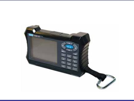
1.Bird Digital Power Meter (DPM)
2.Battery
Note: To install the battery see “Customer Service” on page 50 or refer to the Quick Start Guide.
3.Power Supply
Note: Includes Brick, Cord, 3 Intl Adaptors, and cigarette adaptor
4.USB SeaLatch® Cable, 6’
5.DB9 Cable, 10’
6.Soft Case
7.Accessory Pack
8.Carabiner
9.Tri-Lingual Instruction Book on CD
10.Quick Start Guide
1

Optional Equipment
Directional Power Sensor (DPS)
The Bird 5010B and 5014 Thruline® Sensors require two 43 or APM/DPM elements. The DPS measures both forward and reverse power, so VSWR and other match measurements can be calculated and displayed.
Note: The 5010B replaces the Bird 5010. The 5010 was only compatible with APM/DPM elements, and lacked peak-reading capability. The 5000-XT will still recognize the 5010.
Terminating Power Sensors (TPS)
The Bird 5011and 5015 series terminating power sensors do not require elements. The Bird 5011 and 5015 have a frequency range of 40 MHz – 4 GHz. The 5011EF and 5015-EF sensors have a frequency range of 40 MHz – 12 GHz.
Wideband Power Sensor (WPS)
The Bird 5012B, 5016B, 5017B, 5018B, and 5019B Thruline Sensors do not require elements. The WPS can measure average, peak, or burst power, VSWR, crest factor, and Complementary Cumulative Distribution Function (CCDF).
Attenuators & Accessories
A variety of attenuators and connectors for measuring large powers with the TPS. For a complete list, see
page 51.
Soft Carry Case (P/N 5A5000-1)
Convenient and protective. Cutouts allow operation while in the case.
2
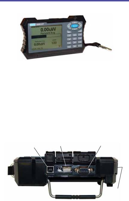
Component Description
Figure 1 Component Description
1. |
Period Key |
Input numeric values. |
2. |
OK/Power Key |
Turns the DPM on or off. |
3. |
+/- Key |
Toggles between positive and negative |
|
|
numbers. |
4. |
Log Key |
Brings up the Logging Menu. |
5. |
Menu Key |
Brings up the Main Menu. |
6. |
Arrow Keys |
Scrolls through menu items. |
7. |
Numeric Keys |
Input numeric values. |
8. |
USB Sensor Port |
Connection for power sensors. |
9. |
COM Sensor Port |
Connection for power sensors. |
10. |
USB Port |
Connection for computer. |
11. |
LCD Display |
Backlit liquid crystal display. |
12. |
External DC |
Connect either the AC adapter or the cigarette |
|
Connector |
lighter adapter. External supplies power the |
|
|
unit and charge the internal battery. |
USB |
USB Sensor |
COM |
|
Port |
Sensor Port |
||
Port |
|||
|
|
DC
Connector
3

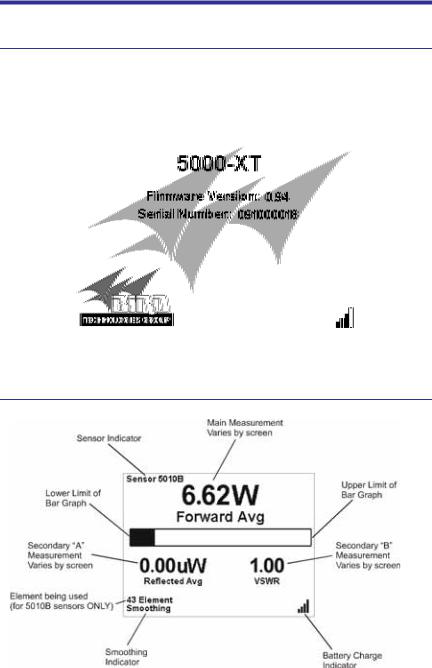
Display Description
Display Units
Shows the measurement mode and units for the display directly above.
Figure 2 Display
Battery Level Indicator
When the external adapter is connected, a lightening bolt icon will indicate the battery is charging. The battery operates off of the external power supply unless it is not present.
When using the internal batteries, the indicator is on continuously. When the battery level indicator is blank, the battery needs to be recharged. If the unit is logging when the battery becomes too low, a notification that logging is being stopped will appear,
Duty Cycle Indicator
For burst power measurements, shows the signal’s duty cycle.
Analog Bar Graph
Displays the dynamic range of the sensor attached. Minimum and maximum depend on sensor.
Offset Indicator
On when an offset is in use.
Power Indicator
If the power exceeds 100% of full scale, “Over” will be displayed.
The numbers in the main measurement will flash.
4
5000-XT Initial User Interface
Startup Screen
Upon initial startup, when from complete shutdown, the splash screen will display for 5 seconds while the file system is being initialized, then it will display the language selection screen.
Note: If this is the first startup, the unit should ask for the language to be used.
5000-XT Main Display Elements
5
6
Chapter 2 |
Installation |
Power Supply
The DPM uses a rechargeable Lithium Ion battery pack. Charge life is about 20 hours with the Bird WPS, 50 hours with other sensors.
The DPM can use an external power source. Using the DPM with the AC adapter or the 12V cigarette lighter adapter will also charge the battery. Charging time from full discharge is 5 hours using the AC adapter. When using the cigarette lighter adapter, charge time will depend on the car battery charge. When the external adapter is connected, a lightening bolt icon will indicate the battery is charging. The battery operates off of the external power supply unless it is not present.
AC Mains Adapter
1.Insert the adapter’s barrel connector into the DPM’s external DC connector (See Figure 1 on page 3).
2.Insert the adapter plug into a wall receptacle.
Automobile Cigarette Lighter Adapter
1.Insert the adapter’s barrel connector into the DPM’s external DC connector.
2.Insert the adapter plug into a cigarette lighter jack.
Connections
WARNING
Never attempt to connect or disconnect RF equipment from the transmission line while RF power is being applied.
Leaking RF energy is a potential health hazard.
Note: If the 5000-XT is connected to a PC when starting or restarting the PC, it may cause the boot process to lock up.
Disconnect the 5000-XT before starting or restarting the PC.
7

Figure 3 DPM Connections
Connecting the Directional Power Sensor (DPS)
WARNING
RF voltage may be present in RF element socket. Keep element in socket during operation.
1.Do one of the following:
For Models 5010, 5010B, 5011, 5012, 5012A, 5012B, 5016, 5016B, 5017, 5017B, 5018, 5018B, 5019, and 5019B:
Connect the Bird DPS to the “Sensor” serial port on the DPM using the sensor cable provided.
8

For Models 5014:
Connect the Bird DPS to the “Sensor” USB port on the DPM using the sensor cable provided.
2.Connect the DPS to the RF line so that the arrow on the sensor points towards the load.
Note: The arrow on the forward element should point towards the load.
Note: The arrow on the reflected element should point towards the source.
Note: Both elements must be either APM/DPM or 43 types, do not mix elements.
3. Set the power on the DPM to the forward element’s power rating.
Figure 4 DPS Element Orientation
Connecting the Wideband Power Sensor (WPS)
1.Do one of the following:
Connect the DPM port on the Bird WPS to the “Sensor” serial port on the DPM using the sensor cable provided.
Connect the DPM port on the Bird WPS to the “Sensor” USB port on the DPM using the sensor cable provided.
2.Connect the WPS to the RF line so that the arrow on the sensor points towards the load.
Connecting the Terminating Power Sensor (TPS)
CAUTION
Discharge all static potentials before connecting the TPS(-EF). Electrostatic shock could damage the sensor.
CAUTION
When connecting the TPS or the TPS-EF, only turn the connector nut. Damage may occur if torque is applied to the sensor body.
9

CAUTION
Do not exceed 2 W average or 125 W peak power for 5 μs when using the TPS or the TPS-EF. Doing so will render the sensor inoperative.
Note: Connections are the same for the Bird 5011 and 5011-EF.
1.Do one of the following:
Connect the DPM port on the Bird TPS to the “Sensor” serial port on the DPM using the sensor cable provided.
Connect the DPM port on the Bird TPS to the “Sensor” USB port on the DPM using the sensor cable provided.
Note: An attenuator or directional coupler should be used with the TPS in most applications.
Example - For an RF source with output between 0.1 and 50 W, use a 40 dB, 50 W attenuator.
2.Connect the TPS RF input to the source (using an attenuator, if appropriate).
Note: Only connect the TPS directly to a source if the RF power will be less than 10 mW.
Resetting the 5000-XT
Pressing and holding down the 5 button for two seconds will reset the unit.
The unit will return to default settings and pop-up the language selection menu.
Upgrading the Firmware
Note: Before performing this procedure, sign on to the internet and go to:
www.bird-technologies.com/products/software/5000-xt/
1.Power on the 5000-XT
2.Connect the USB from the 5000-XT to the PC and wait for the drive to appear.
Note: This could take 30 seconds
3.Create a folder named “FIRMWARE”.
Note: The folder name is case sensitive. If there is already a folder, use the existing folder, but delete any firmware versions already in that folder.
4.Place the updated firmware file into the folder.
Note: This file can be named anything as long as the file extension is
.bin.
10
5.Eject and disconnect the 5000-XT from the PC.
6.Press the Menu key.
7.Select Setup on the Main Menu.
8.Select Update Firmware on the Setup Menu. The Update Firmware file list will display.
9.Select the newly downloaded firmware file from the list.
10.Select ACCEPT when asked “Update System Firmware?”
Note: The file will be checked. If file is corrupt, it will notify as such.
11.The following screens will be displayed:
a.“Loading” screen
b.“Erasing Flash” screen with a progress bar
c.“Writing Flash” screen with a progress bar.
d.“Update Success” screen.
12.Select OK when prompted after this message: “The system will now power down.”.
11
12

Chapter 3 |
Operation |
The Bird Digital Power Meter is very easy to operate. Once a sensor is connected, turn the DPM on and take a reading. Additional commands are available, depending on the sensor used.
Setting Up
1.Connect the sensor.
2.Turn on the DPM.
3.Set the measurement and measurement units.
Note: Refer to the sections following for instructions specific to each sensor.
4.Zero the sensor (WPS and TPS only).
5.Perform the following if the system loss is known or if using an attenuator:
a.Add the losses (in dB) of all components in the system.
Note: Use the loss at the measured frequency.
b.Press OFFSET and enter the total loss in dB.
Note: This will allow the user to read the actual line power. The DPM accepts offsets from –10 to 100 dB, depending on the sensor.
6.Turn on the RF source.
7.Take a reading.
Note: The analog bar graph will respond immediately to changes in the RF power. The major and minor displays will respond after a delay of 1 to 13 seconds, depending on the level of smoothing.
Shutting Down
Press and Hold the “OK” key for 2 seconds. This will put the unit into Sleep mode. It will stop logging in this mode.
Press and hold the “OK” key until the “OK” key illuminates, approximately 8 seconds. Release the key after it illuminates. This will shut the unit down completely.
Performing a Screen Shot
1.Press and hold <.> for two seconds will perform a screen shot of the current screen on the DPM.
2.Select OK to confirm the screen shot.
Note: The image file name will be displayed.
13

Directional Power Sensor (DPS)
WARNING
RF voltage may be present in RF element socket. Keep element in socket during operation.
Setting Scale
Note: The Bird DPS uses Bird Plug-In Elements. These are labeled with a max power and a frequency range.
Note: The transmitter frequency should be within the element range.
Note: Forward and Reflected full scale power must be entered manually.
1.Press Scale.
2.Select the power units (W, mW or kW) with up and down arrow keys.
3.Enter the maximum power of the element in the forward element socket using the numeric keypad and <.> key.
Note: The element’s max power is listed on the element nameplate.
4.Press OK.
Terminating Power Sensor (TPS)
CAUTION
Do not exceed 2 W average or 125 W peak power for 5 μs when using the TPS or the TPS-EF. Doing so will render the sensor inoperative.
Zeroing Sensor
Over time, the sensor’s “zero value” (reading with no applied RF power) can drift due to environmental factors (temperature, humidity, etc.) This can make the readings performed by this sensor less accurate by the drift value. If the drift would be a significant error, re zero the sensor.
1.Ensure the sensor has been connected to the DPM.
2.Press and hold “0” for two seconds to begin zero calibration.
Note: “Zero/Cal” will be displayed and calibration will begin.
14

Note: Zeroing the sensor takes 60 seconds. The bar graph will display calibration progress.
Note: When complete, “PASS” should be displayed.
3.Press Enter to return to normal operation when zeroing is complete.
Note: If “FAIL” is displayed, make sure no RF power is applied to the sensor and perform the procedure again.
TPS-EF
The Bird TPS-EF uses frequency correction factors to allow more accurate measurements. Look at the label on the side of the sensor and find the correction factor for the frequency being measured. Add the correction factor to the other attenuation or coupling factors and enter this as an offset.
Wideband Power Sensor (WPS)
A status LED on the front lights when the WPS is powered, and blinks when the WPS is connected to the DPM.
Zeroing Sensor
Over time, the sensor’s “zero value” (reading with no applied RF power) can drift due to environmental factors (temperature, humidity, etc.) This can make the readings performed by this sensor less accurate by the drift value. If the drift would be a significant error, re zero the sensor.
1.Make sure the sensor has reached a stable operating temperature.
2.Make sure no RF power is applied to the sensor.
3.Press and hold “0” for two seconds to begin zero calibration.
WARNING
Do not interrupt the calibration.
Note: “Zero/Cal” will be displayed and calibration will begin.
Note: Zeroing the sensor takes 60 seconds. The bar graph will display calibration progress.
Note: When complete, “PASS” should be displayed.
4.Press Enter to return to normal operation when zeroing is complete.
Note: c.If “FAIL” is displayed, make sure no RF power is applied to the sensor and perform the procedure again.
15

Video Filter
Except for average power and VSWR measurements, all measurements use a variable video filter to improve accuracy. This filter can be set to either 4.5 kHz, 400 kHz, or Full bandwidth.
Note: It should be as narrow as possible while still being larger than the demodulated signal bandwidth (video bandwidth). Narrowing the filter limits the noise contribution from interfering signals.
Listed below are some common modulation schemes and the appropriate video filter.
|
Video Filter |
Modulation Type |
|
|
|
|
|
|
4.5 kHz |
CW Burst (Burst width > 150 μs), Voice Band |
|
|
|
AM, FM, Phase Modulation, Tetra |
|
|
|
|
|
|
400 kHz |
CW Burst (b.w. > 3 μs), GSM, 50 kHz AM, |
|
|
|
DQPSK (¼ , symbol rate < 24 k/s) |
|
|
Full Bandwidth |
CW Burst (b.w. > 200 ns), CDMA, WCDMA, |
|
|
|
DQPSK (¼ , symbol rate < 200 k/s), DAB/DVB-T |
|
|
|
|
|
Average Mode |
|
|
|
This mode displays the average forward and reflected power.
Note: In average mode, the VSWR or system match can be displayed instead of the reflected power.
Peak Mode
This mode displays the peak envelope power.
Burst Mode
This mode displays the average power in a burst. The burst’s duty cycle is measured by the DPM.
Crest Factor Mode
The crest factor is the ratio of the forward peak power and the forward average power. It is measured in dB.
Note: There are no additional controls in this mode.
CCDF Mode
The CCDF measures the percentage of time the power level is above a threshold. To set the power threshold:
1.Press menu.
2.Select CCDF Limit from the Main Menu.
3.Enter new value.
16
 Loading...